Embed Size (px)
Citation preview
2MPLS-ARCH-sprevidi-0699 © 1999, Cisco Systems, Inc.
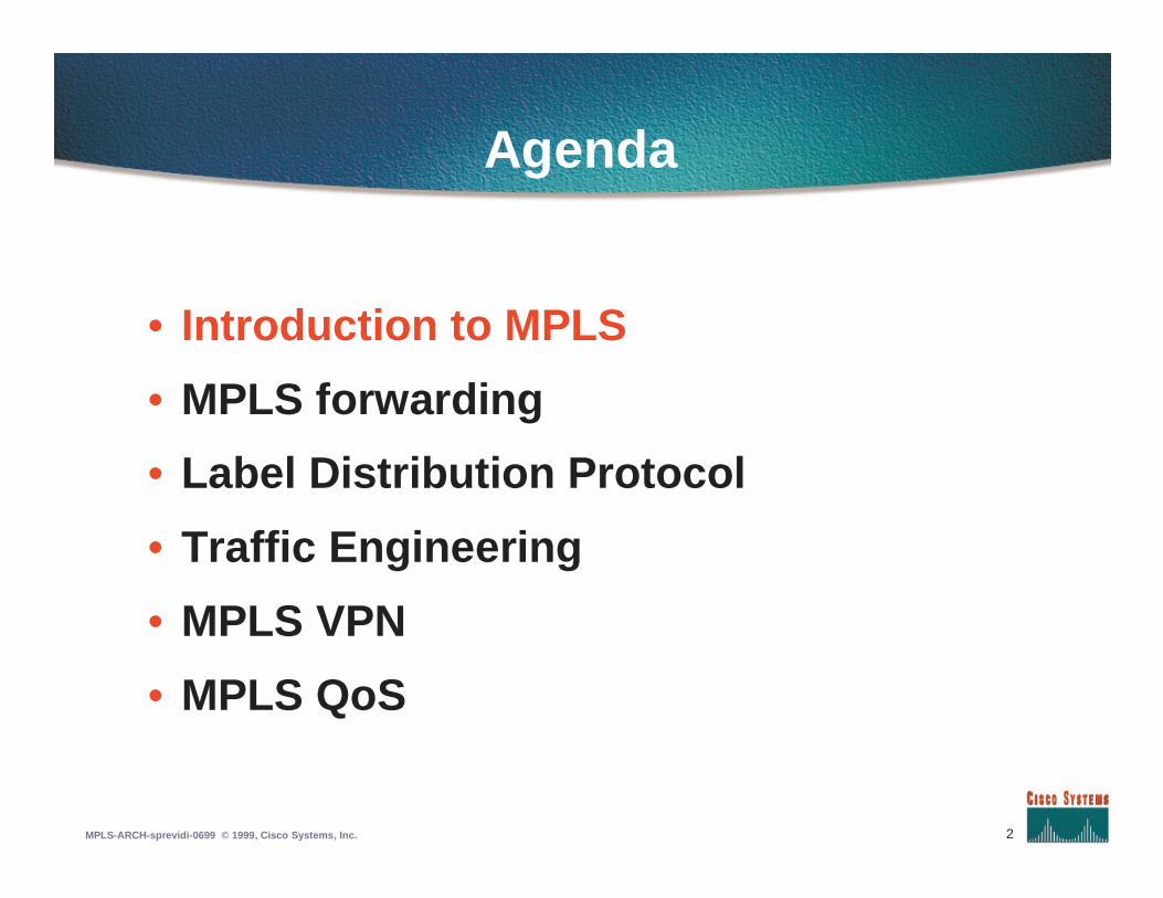
Agenda
• Introduction to MPLS
• MPLS forwarding
• Label Distribution Protocol
• Traffic Engineering
• MPLS VPN
• MPLS QoS
3MPLS-ARCH-sprevidi-0699 © 1999, Cisco Systems, Inc.
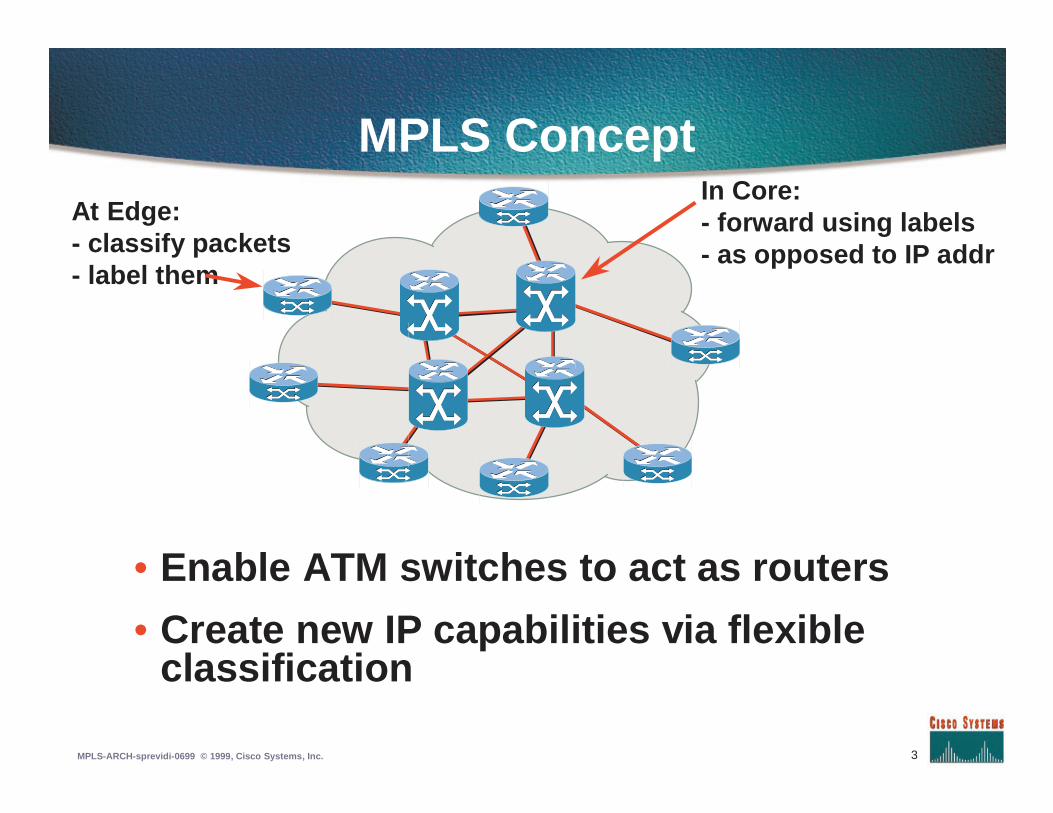
MPLS Concept
• Enable ATM switches to act as routers
• Create new IP capabilities via flexibleclassification
At Edge:- classify packets- label them
In Core:- forward using labels- as opposed to IP addr
4MPLS-ARCH-sprevidi-0699 © 1999, Cisco Systems, Inc.
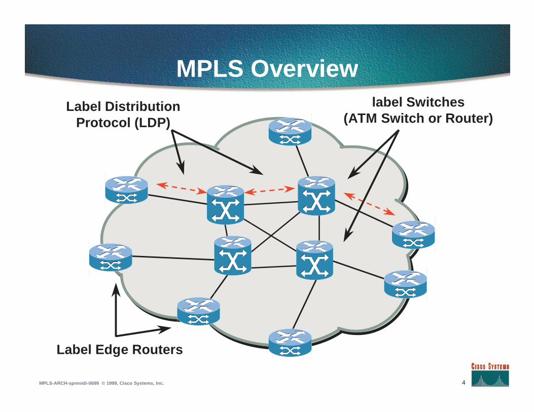
MPLS Overviewlabel Switches
(ATM Switch or Router)Label Distribution
Protocol (LDP)
Label Edge Routers
5MPLS-ARCH-sprevidi-0699 © 1999, Cisco Systems, Inc.
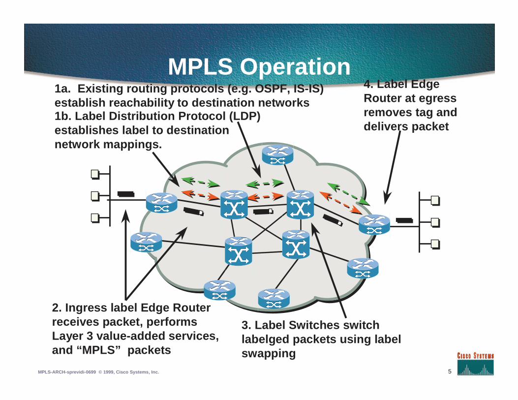
MPLS Operation1a. Existing routing protocols (e.g. OSPF, IS-IS)establish reachability to destination networks1b. Label Distribution Protocol (LDP)establishes label to destinationnetwork mappings.
2. Ingress label Edge Routerreceives packet, performsLayer 3 value-added services,and “MPLS” packets
3. Label Switches switchlabelged packets using labelswapping
4. Label EdgeRouter at egressremoves tag anddelivers packet
6MPLS-ARCH-sprevidi-0699 © 1999, Cisco Systems, Inc.
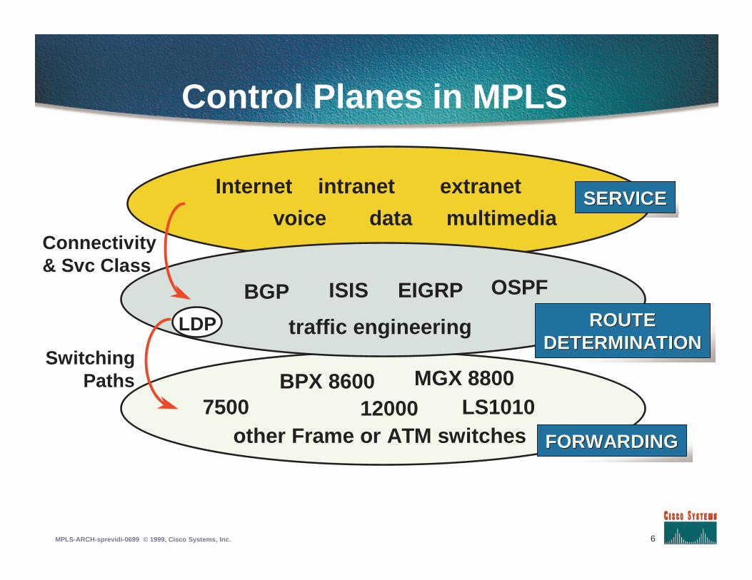
Control Planes in MPLS
7500 12000BPX 8600
LS1010
BGP
LDP
ISIS OSPF
Internet intranet extranet
traffic engineeringSwitching
Paths
FORWARDINGFORWARDING
ROUTEROUTEDETERMINATIONDETERMINATION
SERVICESERVICEvoice data multimedia
Connectivity& Svc Class
other Frame or ATM switches
EIGRP
MGX 8800
7MPLS-ARCH-sprevidi-0699 © 1999, Cisco Systems, Inc.
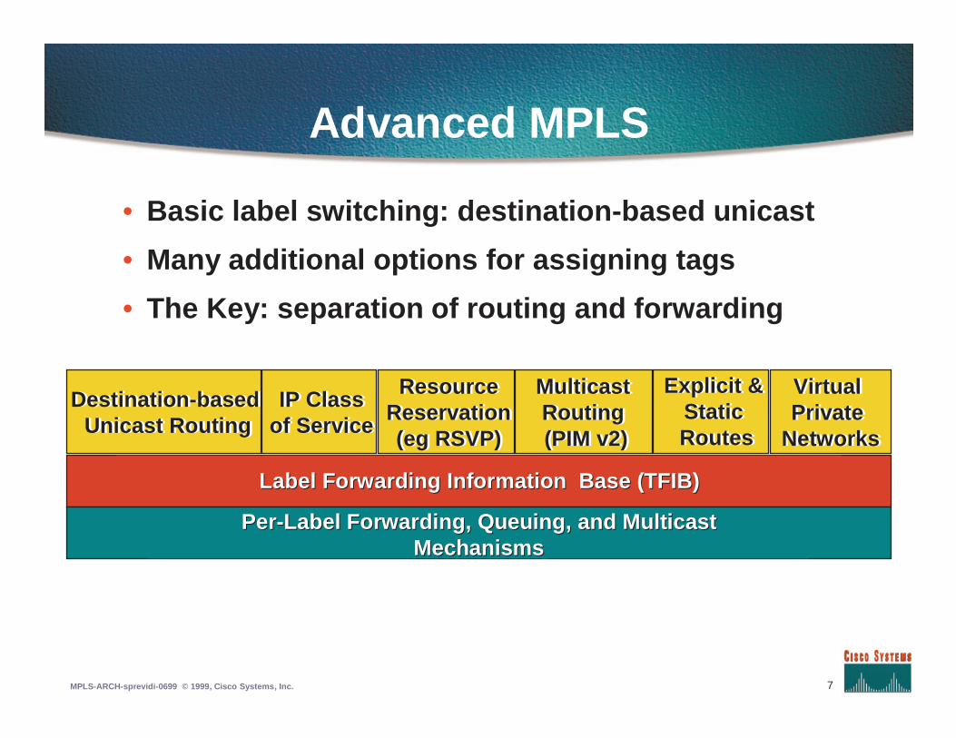
Advanced MPLS
• Basic label switching: destination-based unicast
• Many additional options for assigning tags
• The Key: separation of routing and forwarding
Destination-basedUnicast Routing
Destination-basedUnicast Routing
Label Forwarding Information Base (TFIB)Label Forwarding Information Base (TFIB)
PerPer--Label Forwarding, Queuing, and MulticastLabel Forwarding, Queuing, and MulticastMechanismsMechanisms
IP Classof ServiceIP Class
of Service
ResourceReservation(eg RSVP)
ResourceReservation(eg RSVP)
MulticastRouting(PIM v2)
MulticastRouting(PIM v2)
Explicit &StaticRoutes
Explicit &StaticRoutes
VirtualPrivate
Networks
VirtualPrivate
Networks
8MPLS-ARCH-sprevidi-0699 © 1999, Cisco Systems, Inc.
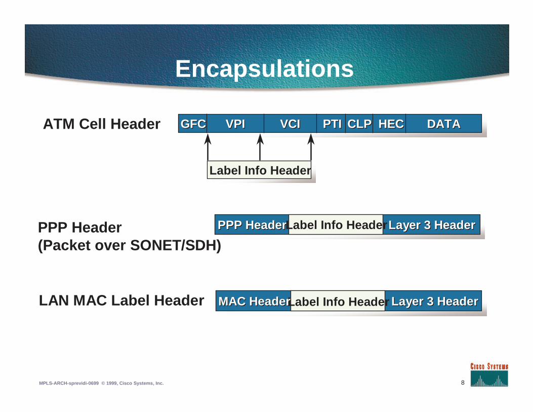
Encapsulations
PPP Header(Packet over SONET/SDH)
ATM Cell Header
LAN MAC Label Header
HECHEC DATADATACLPCLPPTIPTIVCIVCIGFCGFC VPIVPI
Label Info Header
PPP HeaderPPP Header Layer 3 HeaderLayer 3 HeaderLabel Info Header
Label Info Header Layer 3 HeaderLayer 3 HeaderMAC HeaderMAC Header
9MPLS-ARCH-sprevidi-0699 © 1999, Cisco Systems, Inc.
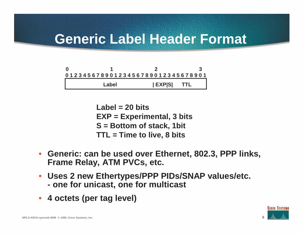
Generic Label Header Format
• Generic: can be used over Ethernet, 802.3, PPP links,Frame Relay, ATM PVCs, etc.
• Uses 2 new Ethertypes/PPP PIDs/SNAP values/etc.- one for unicast, one for multicast
• 4 octets (per tag level)
Label = 20 bitsEXP = Experimental, 3 bitsS = Bottom of stack, 1bitTTL = Time to live, 8 bits
0 1 2 30 1 2 3 4 5 6 7 8 9 0 1 2 3 4 5 6 7 8 9 0 1 2 3 4 5 6 7 8 9 0 1
Label | EXP|S| TTL
10MPLS-ARCH-sprevidi-0699 © 1999, Cisco Systems, Inc.
ATM MPLS
• VPI/VCI field is used as a ‘tag’
• Label is applied to each cell, not wholepacket
• Label swapping = ATM switching
11MPLS-ARCH-sprevidi-0699 © 1999, Cisco Systems, Inc.
Carrying Labels on EthernetLinks
• Extra four bytes might lead to fragmentation of 1492-bytepackets
• Path MTU discovery will detect need to fragment (MTUdiscover packets will be sent tagged)
• But: many Ethernet links actually support 1500 or 1508-byte packets
• And: most packets will normally be carried over ATM, orPPP/SDH links, not Ethernet
12MPLS-ARCH-sprevidi-0699 © 1999, Cisco Systems, Inc.
MPLS Basics: Summary
• MPLS puts IP routing functions on ATMswitches. This provides better IP and ATMintegration and better scaling.
• On non-ATM equipment, MPLS simplifies theforwarding operation and introduces‘lightweight virtual circuits’. This allowsadvanced features like MPLS TrafficEngineering.
13MPLS-ARCH-sprevidi-0699 © 1999, Cisco Systems, Inc.
Agenda
• Introduction to MPLS
• MPLS forwarding
• Label Distribution Protocol
• Traffic Engineering
• MPLS VPN
• MPLS QoS
14MPLS-ARCH-sprevidi-0699 © 1999, Cisco Systems, Inc.
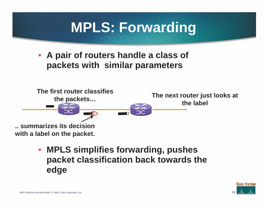
MPLS: Forwarding
• A pair of routers handle a class ofpackets with similar parameters
The first router classifiesthe packets…
.. summarizes its decisionwith a label on the packet.
The next router just looks atthe label
• MPLS simplifies forwarding, pushespacket classification back towards theedge
15MPLS-ARCH-sprevidi-0699 © 1999, Cisco Systems, Inc.
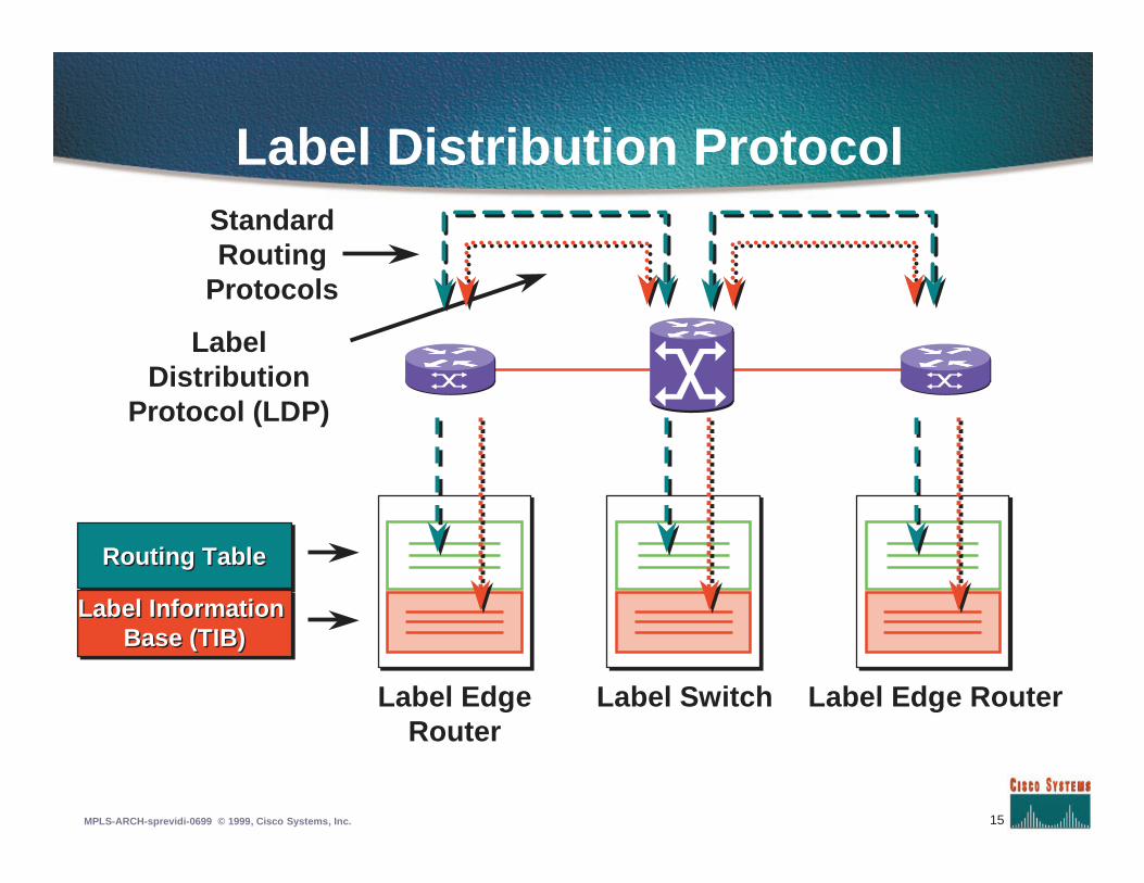
Label Distribution Protocol
Label InformationBase (TIB)
Label InformationBase (TIB)
StandardRouting
Protocols
Label Edge Router
LabelDistribution
Protocol (LDP)
Routing TableRouting Table
Label SwitchLabel EdgeRouter
16MPLS-ARCH-sprevidi-0699 © 1999, Cisco Systems, Inc.
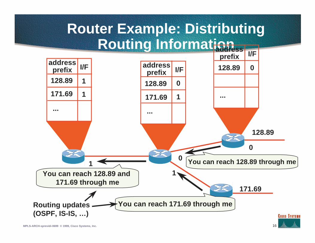
Router Example: DistributingRouting Information
0
11
128.89
171.69
0
You can reach 171.69 through me
You can reach 128.89 and171.69 through me
Routing updates(OSPF, IS-IS, …)
You can reach 128.89 through me
...
128.89
171.69
addressprefix I/F
1
1
...
128.89
171.69
addressprefix I/F
0
1 ...
128.89
addressprefix I/F
0
17MPLS-ARCH-sprevidi-0699 © 1999, Cisco Systems, Inc.
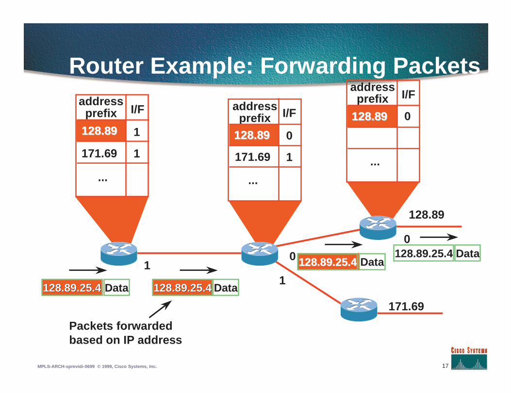
Router Example: Forwarding Packets
0
11
128.89
171.69
0
128.89.25.4128.89.25.4 Data 128.89.25.4128.89.25.4 Data
128.89.25.4128.89.25.4 Data128.89.25.4 Data
Packets forwardedbased on IP address
...
128.89128.89
171.69
addressprefix I/F
1
1
...
128.89128.89
171.69
addressprefix I/F
0
1 ...
128.89128.89
addressprefix I/F
0
18MPLS-ARCH-sprevidi-0699 © 1999, Cisco Systems, Inc.
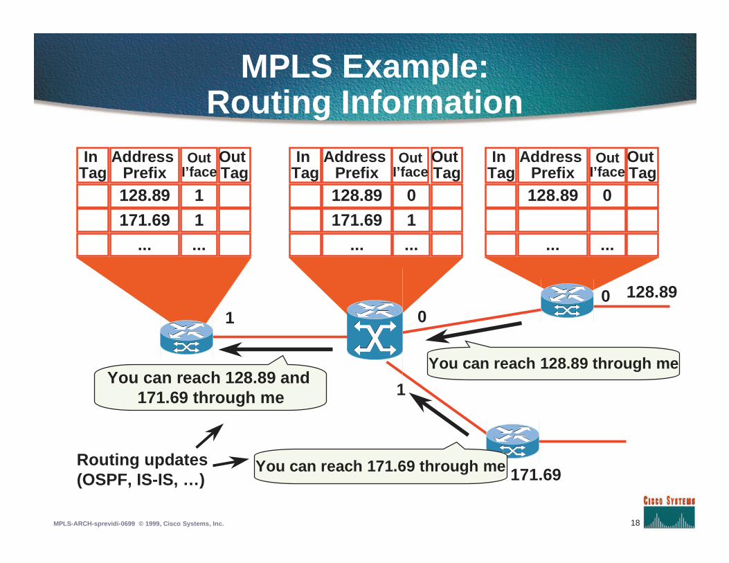
MPLS Example:Routing Information
128.89
171.69
1
01
InTag
AddressPrefix128.89
171.69...
OutI’face
1
1...
OutTag
InTag
AddressPrefix128.89
171.69...
OutI’face
0
1...
OutTag
InTag
AddressPrefix128.89
...
OutI’face
0
...
OutTag
0
You can reach 171.69 through me
You can reach 128.89 and171.69 through me
Routing updates(OSPF, IS-IS, …)
You can reach 128.89 through me
19MPLS-ARCH-sprevidi-0699 © 1999, Cisco Systems, Inc.
3
128.89
171.69...
1
1...
128.89
128.89171.69
0
01
128.89
...
0
...
InTag
InTag
2
1
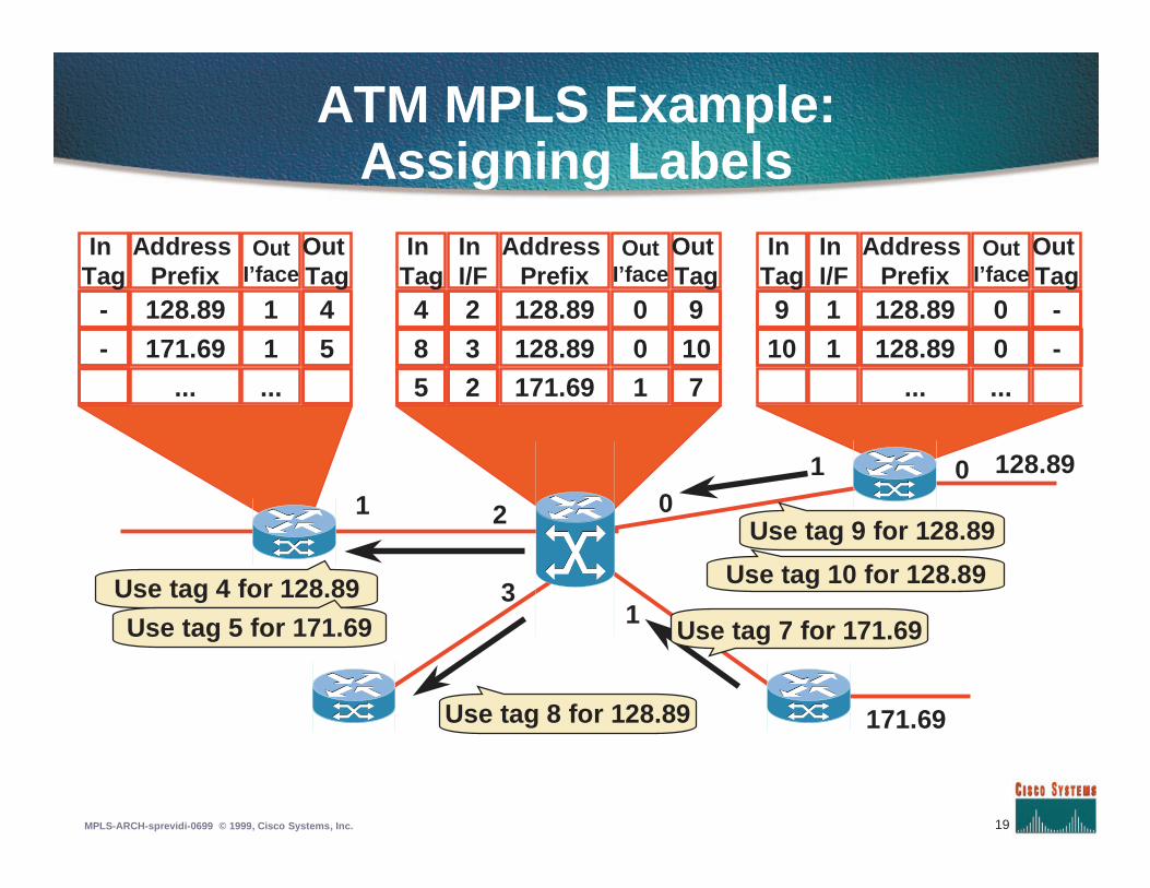
ATM MPLS Example:Assigning Labels
128.89
171.69
1
010
Use tag 9 for 128.89
Use tag 10 for 128.89
Use tag 7 for 171.69
Use tag 4 for 128.89
Use tag 5 for 171.69
Use tag 8 for 128.89
1
1 128.89 0
-
-
9
10
9
107
2
32
4
85
4
5
-
-
InTag
AddressPrefix
OutI’face
OutTag
InI/F
AddressPrefix
OutI’face
OutTag
InI/F
AddressPrefix
OutI’face
OutTag
20MPLS-ARCH-sprevidi-0699 © 1999, Cisco Systems, Inc.
128.89
171.69...
1
1...
128.89
171.69...
0
1...
128.89
...
0
...
InTag
InTag
2
1
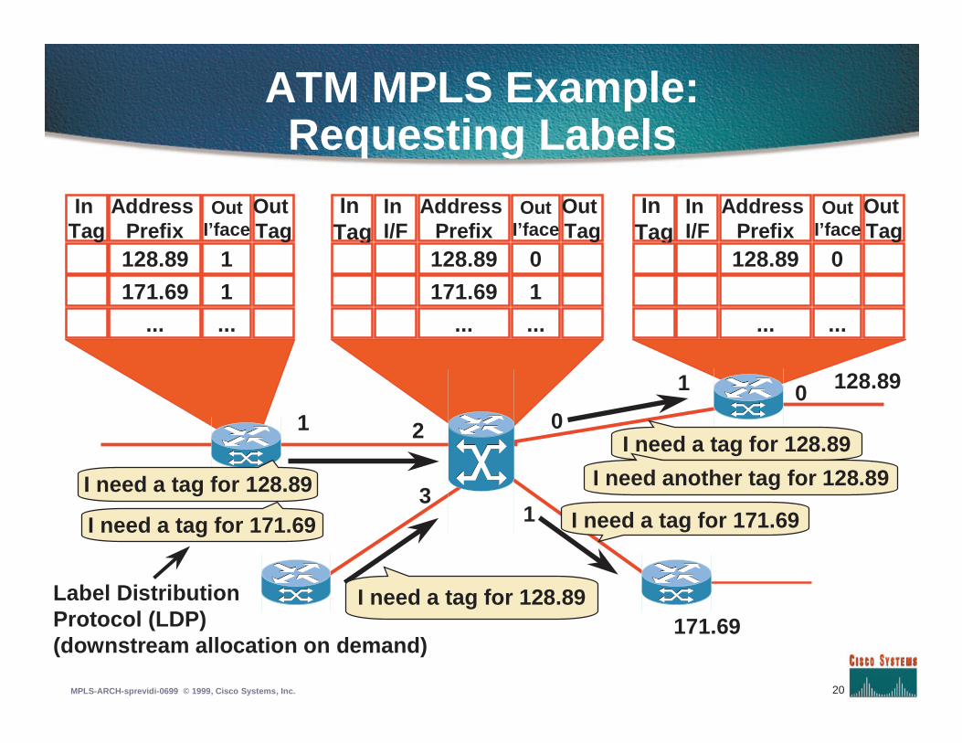
ATM MPLS Example:Requesting Labels
128.89
171.69
1
010
I need a tag for 128.89
Label DistributionProtocol (LDP)(downstream allocation on demand)
I need a tag for 128.89
I need a tag for 171.69
I need another tag for 128.89
I need a tag for 128.89
I need a tag for 171.693
InTag
AddressPrefix
OutI’face
OutTag
InI/F
AddressPrefix
OutI’face
OutTag
InI/F
AddressPrefix
OutI’face
OutTag
21MPLS-ARCH-sprevidi-0699 © 1999, Cisco Systems, Inc.
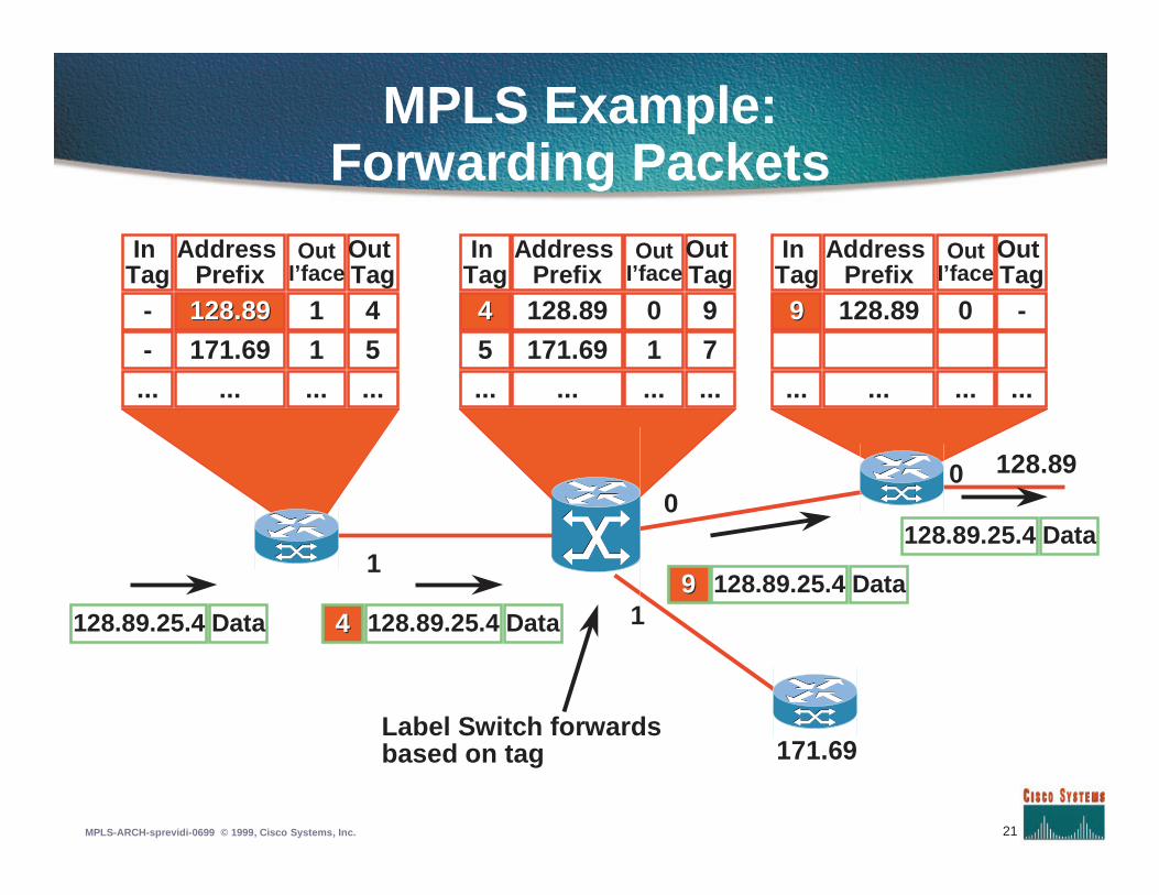
MPLS Example:Forwarding Packets
128.89
171.69
1
0
1
InTag
-
-...
AddressPrefix
128.89128.89
171.69...
OutI’face
1
1...
OutTag
4
5...
InTag
44
5...
AddressPrefix128.89
171.69...
OutI’face
0
1...
OutTag
9
7...
128.89.25.4 Data44128.89.25.4 Data
128.89.25.4 Data
128.89.25.4 Data99
InTag
99
...
AddressPrefix128.89
...
OutI’face
0
...
OutTag
-
...
0
Label Switch forwardsbased on tag
22MPLS-ARCH-sprevidi-0699 © 1999, Cisco Systems, Inc.
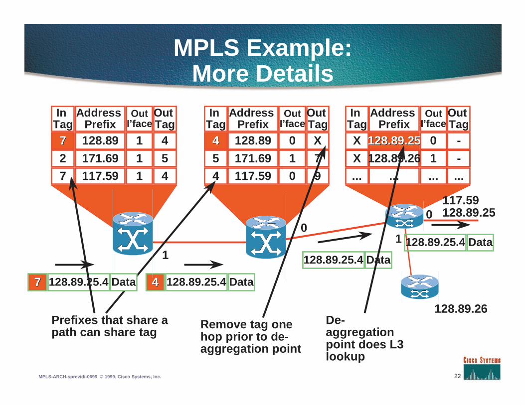
MPLS Example:More Details
117.59128.89.25
128.89.26
10
1
InTag
77
27
AddressPrefix128.89
171.69
OutI’face
1
11
OutTag
4
54
InTag
44
54
AddressPrefix128.89
171.69
OutI’face
0
10
OutTagX
79
128.89.25.4 Data44
128.89.25.4 Data
128.89.25.4 Data
InTag
X
...
AddressPrefix
128.89.25128.89.25
...
OutI’face
0
...
OutTag
-
...
0
Prefixes that share apath can share tag
128.89.26 1 -X117.59117.59
128.89.25.4 Data77
Remove tag onehop prior to de-aggregation point
De-aggregationpoint does L3lookup
23MPLS-ARCH-sprevidi-0699 © 1999, Cisco Systems, Inc.
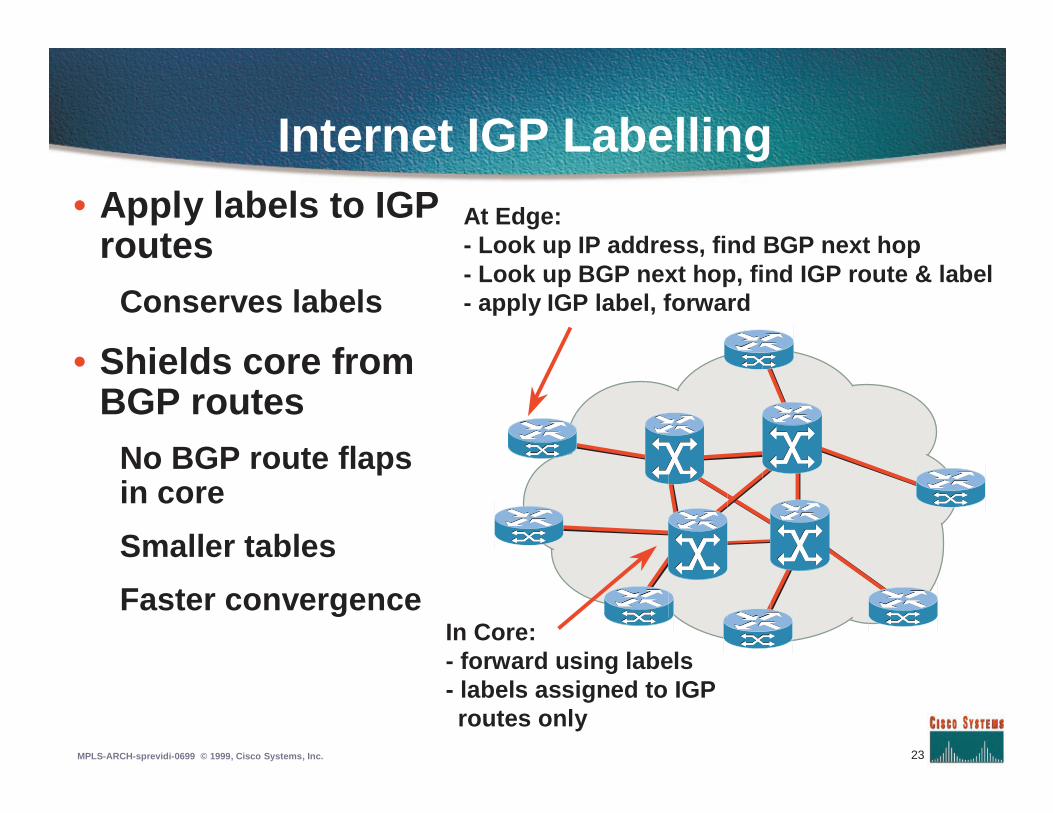
Internet IGP Labelling• Apply labels to IGP
routesConserves labels
• Shields core fromBGP routes
No BGP route flapsin core
Smaller tables
Faster convergence
At Edge:- Look up IP address, find BGP next hop- Look up BGP next hop, find IGP route & label- apply IGP label, forward
In Core:- forward using labels- labels assigned to IGP
routes only
24MPLS-ARCH-sprevidi-0699 © 1999, Cisco Systems, Inc.
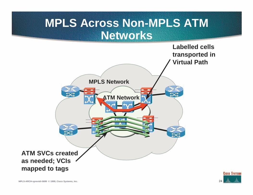
MPLS Across Non-MPLS ATMNetworks
ATM Network
MPLS Network
Labelled cellstransported inVirtual Path
ATM SVCs createdas needed; VCIsmapped to tags
25MPLS-ARCH-sprevidi-0699 © 1999, Cisco Systems, Inc.
Label Forwarding: Summary
• Helps routing scale: analyze packetsonly at edge
• Makes full-featured routing feasibleLabelling on destination, source, ToS, (RSVP)
Multicast labelling, other modes
• Will run on any MAC layer
• Basic mechanism is extensibleto traffic engineering, multicast
26MPLS-ARCH-sprevidi-0699 © 1999, Cisco Systems, Inc.
Agenda
• Introduction to MPLS
• MPLS forwarding
• Label Distribution Protocol
• Traffic Engineering
• MPLS VPN
• MPLS QoS
27MPLS-ARCH-sprevidi-0699 © 1999, Cisco Systems, Inc.
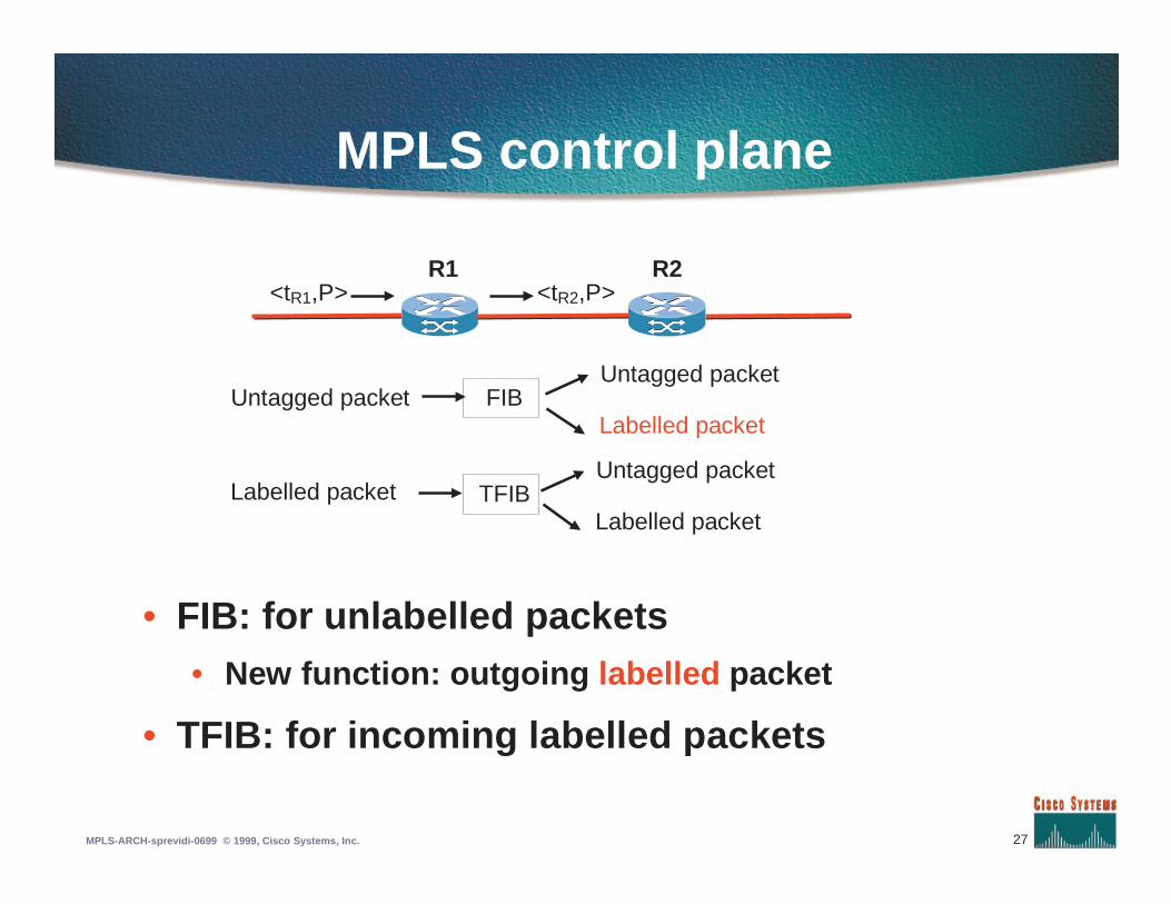
MPLS control plane
• FIB: for unlabelled packets• New function: outgoing labelled packet
• TFIB: for incoming labelled packets
<tR1,P> <tR2,P>R1 R2
FIBUntagged packet
Labelled packet
TFIBUntagged packet
Labelled packet
Untagged packet
Labelled packet
28MPLS-ARCH-sprevidi-0699 © 1999, Cisco Systems, Inc.
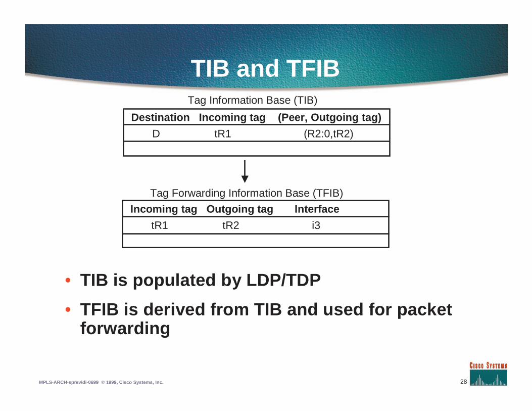
TIB and TFIB
• TIB is populated by LDP/TDP
• TFIB is derived from TIB and used for packetforwarding
Destination Incoming tag (Peer, Outgoing tag)
D tR1 (R2:0,tR2)
Tag Information Base (TIB)
Incoming tag Outgoing tag Interface
tR1 tR2 i3
Tag Forwarding Information Base (TFIB)
29MPLS-ARCH-sprevidi-0699 © 1999, Cisco Systems, Inc.
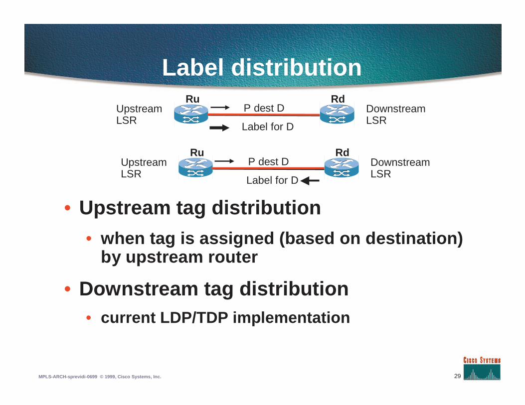
Label distribution
• Upstream tag distribution
• when tag is assigned (based on destination)by upstream router
• Downstream tag distribution• current LDP/TDP implementation
Upstream LSR
P dest DRu Rd
Label for D
Downstream LSR
Upstream LSR
P dest DRu Rd
Label for D
Downstream LSR
30MPLS-ARCH-sprevidi-0699 © 1999, Cisco Systems, Inc.
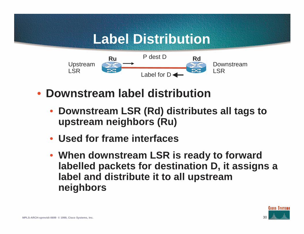
Label Distribution
• Downstream label distribution
• Downstream LSR (Rd) distributes all tags toupstream neighbors (Ru)
• Used for frame interfaces
• When downstream LSR is ready to forwardlabelled packets for destination D, it assigns alabel and distribute it to all upstreamneighbors
Upstream LSR
P dest DRu Rd
Label for D
Downstream LSR
31MPLS-ARCH-sprevidi-0699 © 1999, Cisco Systems, Inc.
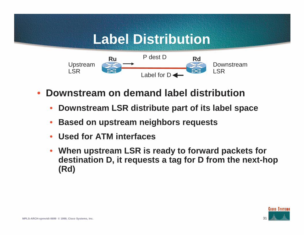
Label Distribution
• Downstream on demand label distribution• Downstream LSR distribute part of its label space
• Based on upstream neighbors requests
• Used for ATM interfaces
• When upstream LSR is ready to forward packets fordestination D, it requests a tag for D from the next-hop(Rd)
Upstream LSR
P dest DRu Rd
Label for D
Downstream LSR
32MPLS-ARCH-sprevidi-0699 © 1999, Cisco Systems, Inc.
Label Distribution
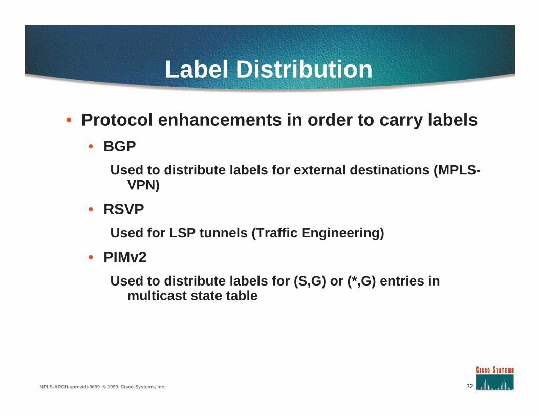
• Protocol enhancements in order to carry labels• BGP
Used to distribute labels for external destinations (MPLS-VPN)
• RSVP
Used for LSP tunnels (Traffic Engineering)
• PIMv2
Used to distribute labels for (S,G) or (*,G) entries inmulticast state table
33MPLS-ARCH-sprevidi-0699 © 1999, Cisco Systems, Inc.
LDP transport
• LDP uses TCP as transport layer
• Well-known TCP port 711
• One TCP session per LDP session
• No multiplexing at this stage
• when label is assigned (based on destination)by upstream router
34MPLS-ARCH-sprevidi-0699 © 1999, Cisco Systems, Inc.
LDP Identifier
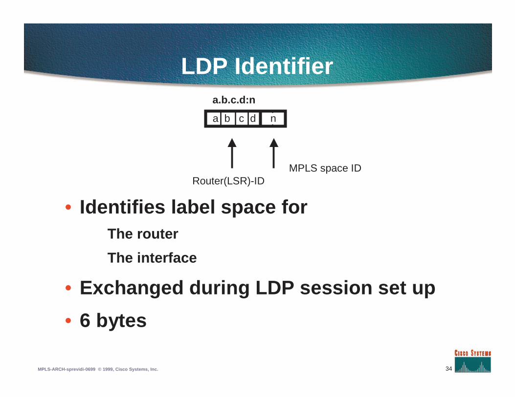
• Identifies label space forThe router
The interface
• Exchanged during LDP session set up
• 6 bytes
a.b.c.d:n
a b c d n
Router(LSR)-IDMPLS space ID
35MPLS-ARCH-sprevidi-0699 © 1999, Cisco Systems, Inc.
LDP neighbor discovery
• Discovery is done through Hello packets• Hello are periodically sent via UDP
• Hello are sent on all label-enabled interfaces
• Source address is the outgoing interface
• Hellos packets containLDP Identifier
Label space
36MPLS-ARCH-sprevidi-0699 © 1999, Cisco Systems, Inc.
LDP Session
• Once discovery is done the LDP sessionis established over TCP
• LSRs send periodically keepalive LDPpackets to monitor the session
37MPLS-ARCH-sprevidi-0699 © 1999, Cisco Systems, Inc.
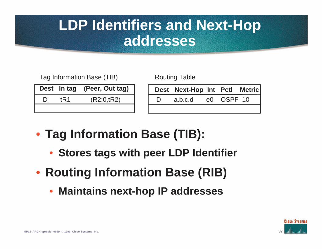
LDP Identifiers and Next-Hopaddresses
• Tag Information Base (TIB):
• Stores tags with peer LDP Identifier
• Routing Information Base (RIB)
• Maintains next-hop IP addresses
Dest In tag (Peer, Out tag)
D tR1 (R2:0,tR2)
Tag Information Base (TIB)
D a.b.c.d e0 OSPF 10
Routing Table
Dest Next-Hop Int Pctl Metric
38MPLS-ARCH-sprevidi-0699 © 1999, Cisco Systems, Inc.
LDP Identifiers and Next-HopAddresses
• TFIB requests labels assigned by next-hop todestination
• LDP maps next-hop address into peer LDPIdentifier in order to retrieve a label
• LSRs advertise interface addresses via LDP
• LSRs map peer LDP ID to addressesUsing learned addresses
39MPLS-ARCH-sprevidi-0699 © 1999, Cisco Systems, Inc.
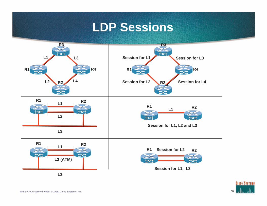
LDP Sessions
R1
R2
R3
R4
L1 L3
L2 L4
R1 R2L1
L2
L3
R1 R2L1
Session for L1, L2 and L3
R1
R2
R3
R4
Session for L1 Session for L3
Session for L2 Session for L4
R1 R2L1
L2 (ATM)
L3
R1 R2Session for L2
Session for L1, L3
40MPLS-ARCH-sprevidi-0699 © 1999, Cisco Systems, Inc.
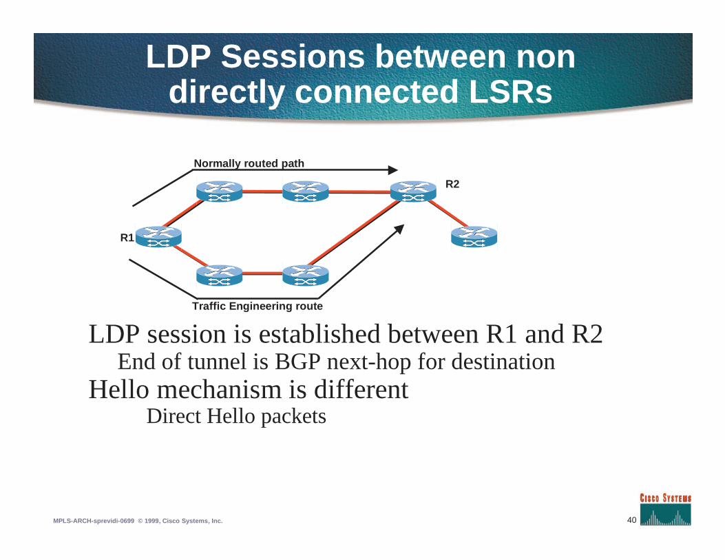
LDP Sessions between nondirectly connected LSRs
Normally routed path
Traffic Engineering route
R2
R1
LDP session is established between R1 and R2End of tunnel is BGP next-hop for destination
Hello mechanism is differentDirect Hello packets
41MPLS-ARCH-sprevidi-0699 © 1999, Cisco Systems, Inc.
Label Distribution Protocol (LDP)
• Run in parallel with routing protocols
• Distributes <tag,prefix> bindings
• Incremental updates over TCP
• Other tag distribution mechanisms canrun in parallel with it
42MPLS-ARCH-sprevidi-0699 © 1999, Cisco Systems, Inc.
Agenda
• Introduction to MPLS
• MPLS forwarding
• Label Distribution Protocol
• Traffic Engineering
• MPLS VPN
• MPLS QoS
43MPLS-ARCH-sprevidi-0699 © 1999, Cisco Systems, Inc.
Traffic Engineering Motivation
• “For a given network topology and trafficload, where should my traffic go and howdo I make it go there ?”
44MPLS-ARCH-sprevidi-0699 © 1999, Cisco Systems, Inc.
Traffic Engineering Motivation
• Link not available
• Economics
• Size of pipes
• Failure scenarios
• Unanticipated growth
• Class of service routing
R8
R2
R6
R3R4
R7
R5
R9
R1
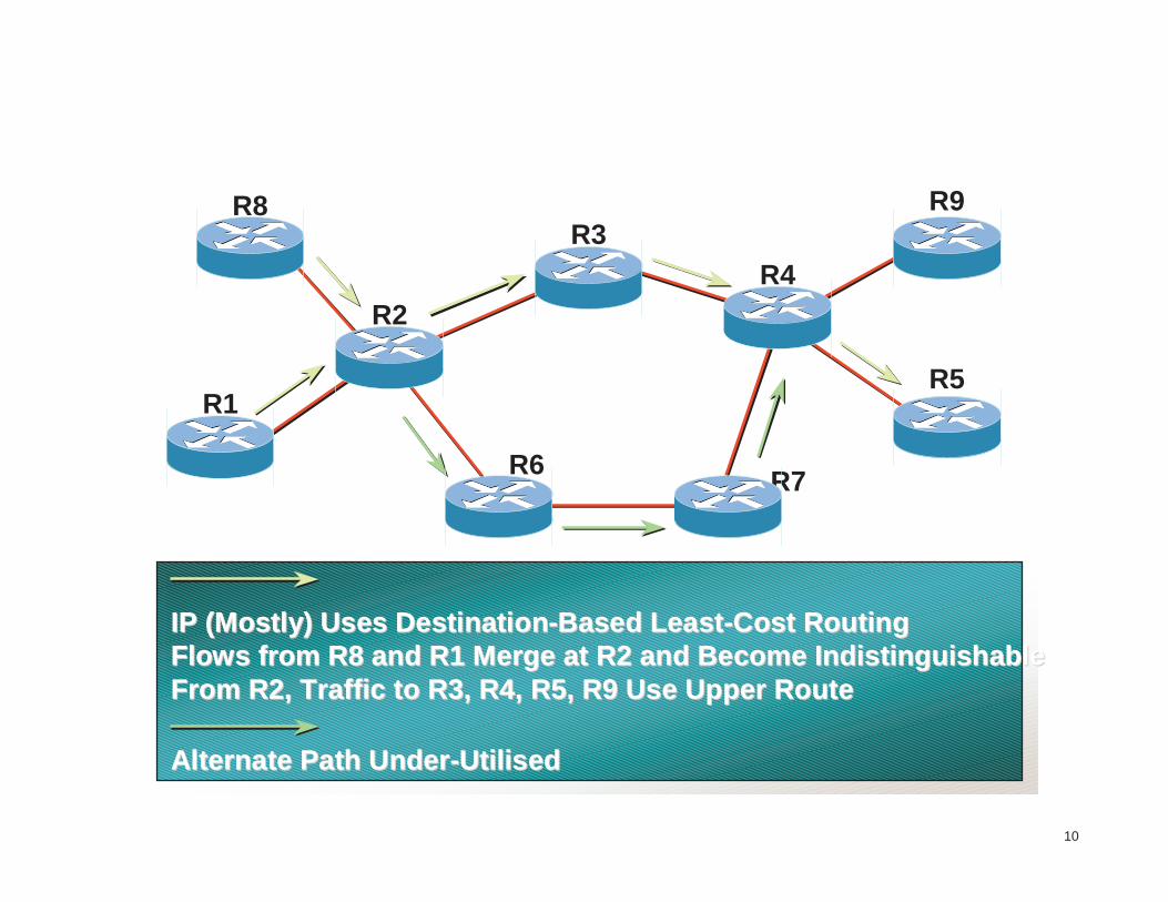
Traffic Engineering
IP (Mostly) Uses DestinationIP (Mostly) Uses Destination--Based LeastBased Least--Cost RoutingCost RoutingFlows from R8 and R1 Merge at R2 and Become IndistinguishableFlows from R8 and R1 Merge at R2 and Become IndistinguishableFrom R2, Traffic to R3, R4, R5, R9 Use Upper RouteFrom R2, Traffic to R3, R4, R5, R9 Use Upper Route
Alternate Path UnderAlternate Path Under--UtilisedUtilised
10
46MPLS-ARCH-sprevidi-0699 © 1999, Cisco Systems, Inc.
LSP tunnels
• Labelled packets are forwarded based ontag, not IP destination
• In conjunction with signaling mechanism.Label forwarding can be used to create amulti-hop LSP tunnel: TE tunnel
• LSP tunnel is used to reach BGP next-hop
47MPLS-ARCH-sprevidi-0699 © 1999, Cisco Systems, Inc.
LSP tunnel setup via RSVP
• RSVP extensions
• Initiated at source router
• Complete path in forward messages
• Label established by reply messages
• Rapid tear down on link failure
48MPLS-ARCH-sprevidi-0699 © 1999, Cisco Systems, Inc.
LSP tunnel setup via RSVP
• Possible future resource capabilities
• Unidirectional data flow
• May traverse ATM LSR, but not begin orend there
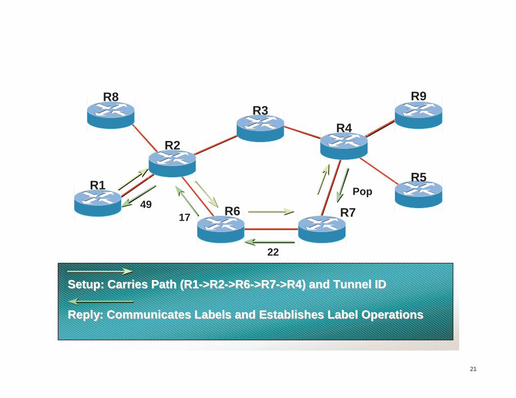
LSP tunnels Setup
Setup: Carries Path (R1Setup: Carries Path (R1-->R2>R2-->R6>R6-->R7>R7-->R4) and Tunnel ID>R4) and Tunnel ID
Reply: Communicates Labels and Establishes Label OperationsReply: Communicates Labels and Establishes Label Operations
22
4917
R8
R2
R6
R3R4
R7
R1R5
R9
21
Pop
50MPLS-ARCH-sprevidi-0699 © 1999, Cisco Systems, Inc.
LSP tunnel configuration
• IOS tunnel interface with tag-switchingencapsulation (not GRE)
• Source route
• Specified as the sequence of IP addresses
• Configured only at the head of the tunnel
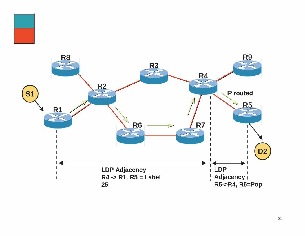
LSP tunnels Labeldistribution
R8
R2
R6
R3R4
R7
R1R5
R9
21
S1
D2
IP routed
LDPAdjacencyR5->R4, R5=Pop
LDP AdjacencyR4 -> R1, R5 = Label25
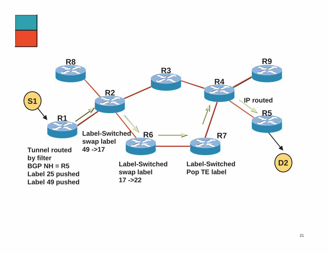
LSP tunnels Forwarding
Label-Switchedswap label49 ->17
R8
R2
R6
R3R4
R7
R1R5
R9
21
S1
D2Label-Switchedswap label17 ->22
Label-SwitchedPop TE label
IP routed
Tunnel routedby filterBGP NH = R5Label 25 pushedLabel 49 pushed
53MPLS-ARCH-sprevidi-0699 © 1999, Cisco Systems, Inc.
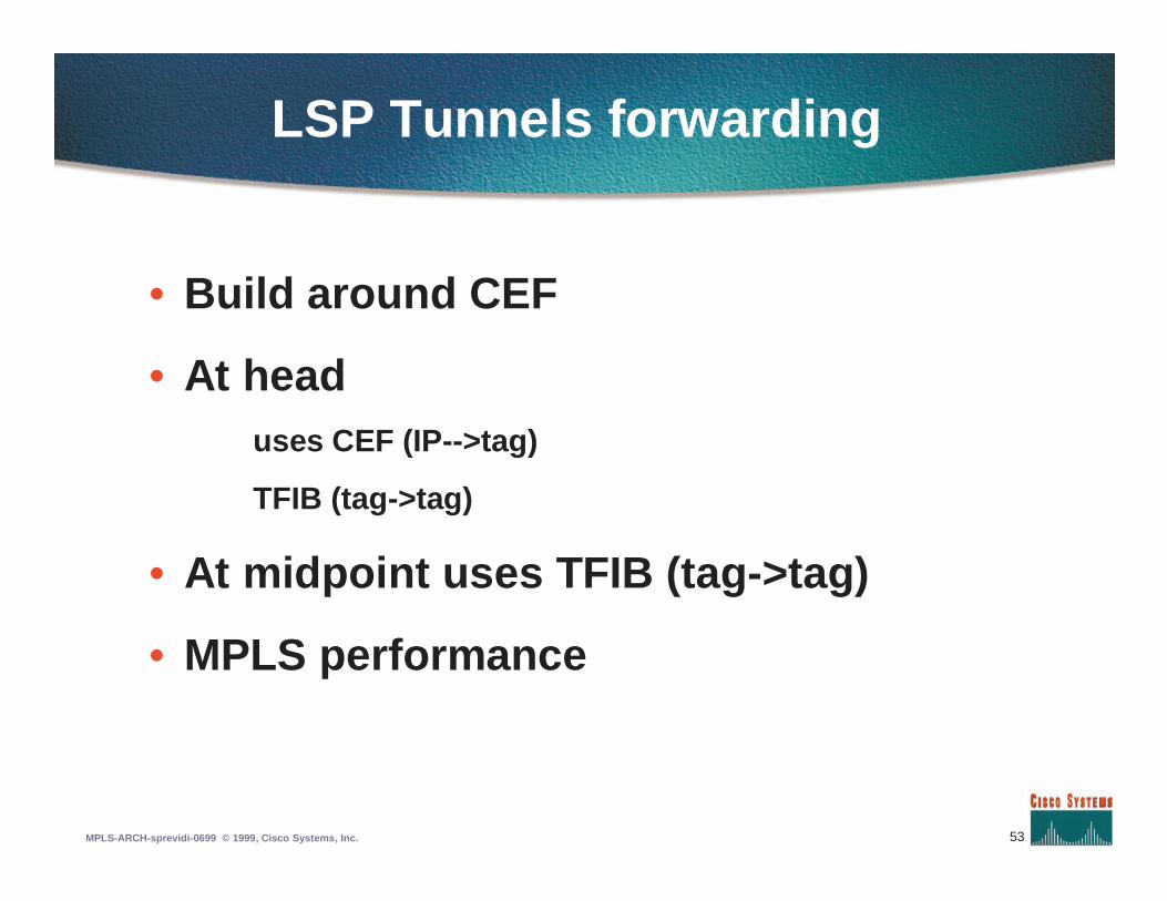
LSP Tunnels forwarding
• Build around CEF
• At headuses CEF (IP-->tag)
TFIB (tag->tag)
• At midpoint uses TFIB (tag->tag)
• MPLS performance
54MPLS-ARCH-sprevidi-0699 © 1999, Cisco Systems, Inc.
Agenda
• Introduction to MPLS
• MPLS forwarding
• Label Distribution Protocol
• Traffic Engineering
• MPLS VPN
• MPLS QoS
55MPLS-ARCH-sprevidi-0699 © 1999, Cisco Systems, Inc.
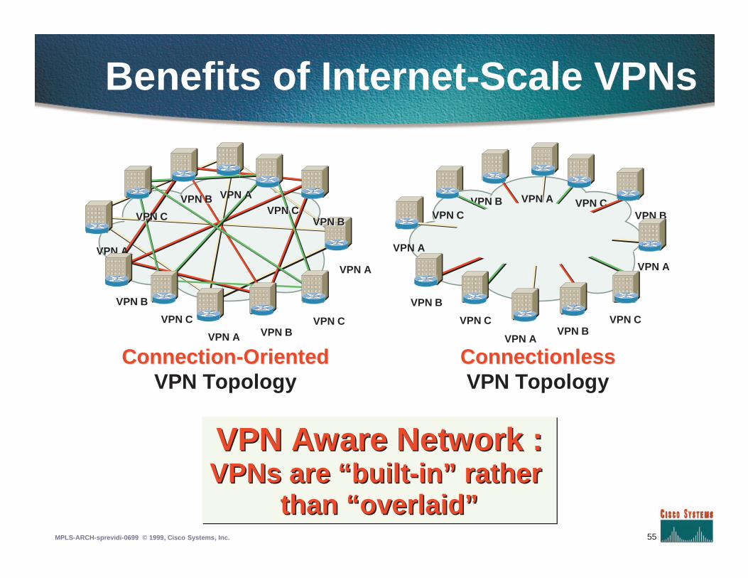
ConnectionConnection--OrientedOrientedVPN Topology
ConnectionlessConnectionlessVPN Topology
VPN A
VPN B
VPN C
VPN A VPN BVPN C
VPN A
VPN BVPN BVPN CVPN C
VPN AVPN A
VPN CVPN C
VPN BVPN B
VPN CVPN C
VPN A
VPN B
VPN C
VPN AVPN B
VPN C
VPN A
VPN BVPN CVPN CVPN AVPN AVPN BVPN B
Benefits of Internet-Scale VPNs
VPN Aware Network :VPNs are “built-in” rather
than “overlaid”
VPN Aware Network :VPN Aware Network :VPNsVPNs are “builtare “built--in” ratherin” rather
than “overlaid”than “overlaid”
56MPLS-ARCH-sprevidi-0699 © 1999, Cisco Systems, Inc.
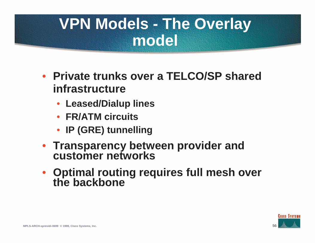
VPN Models - The Overlay model
• Private trunks over a TELCO/SP sharedinfrastructure• Leased/Dialup lines• FR/ATM circuits• IP (GRE) tunnelling
• Transparency between provider andcustomer networks
• Optimal routing requires full mesh overthe backbone
57MPLS-ARCH-sprevidi-0699 © 1999, Cisco Systems, Inc.
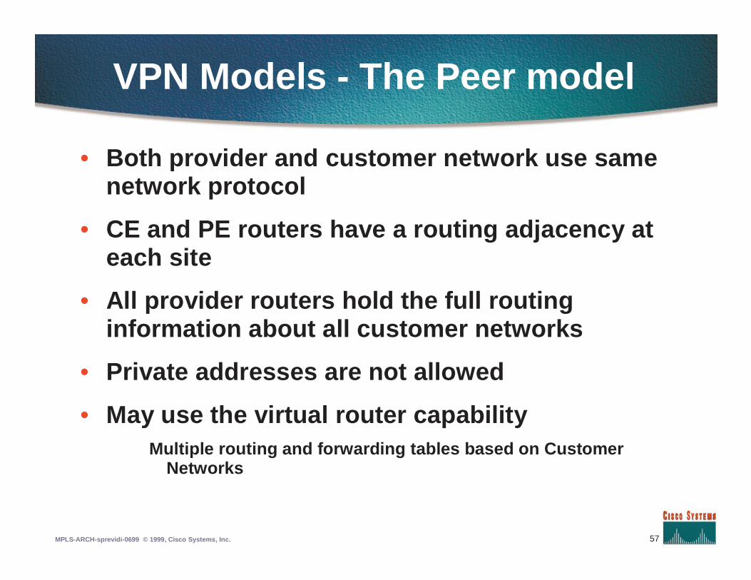
VPN Models - The Peer model
• Both provider and customer network use samenetwork protocol
• CE and PE routers have a routing adjacency ateach site
• All provider routers hold the full routinginformation about all customer networks
• Private addresses are not allowed
• May use the virtual router capabilityMultiple routing and forwarding tables based on Customer
Networks
58MPLS-ARCH-sprevidi-0699 © 1999, Cisco Systems, Inc.
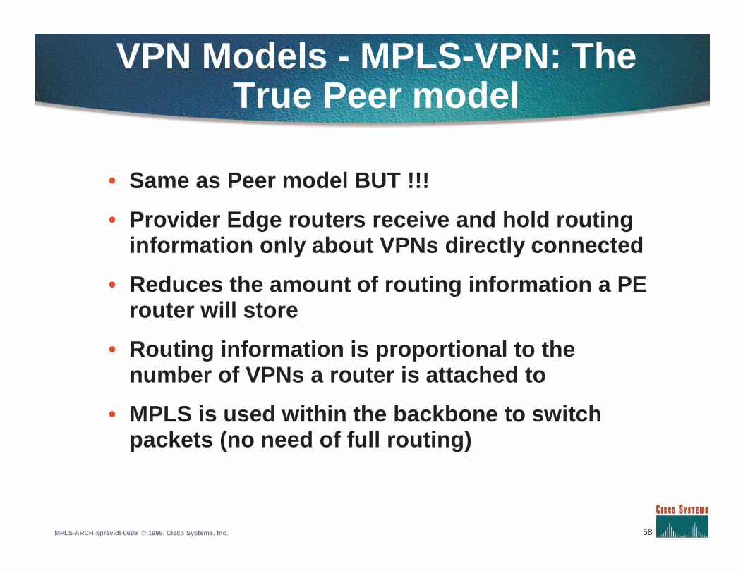
VPN Models - MPLS-VPN: The True Peer model
• Same as Peer model BUT !!!
• Provider Edge routers receive and hold routinginformation only about VPNs directly connected
• Reduces the amount of routing information a PErouter will store
• Routing information is proportional to thenumber of VPNs a router is attached to
• MPLS is used within the backbone to switchpackets (no need of full routing)
59MPLS-ARCH-sprevidi-0699 © 1999, Cisco Systems, Inc.
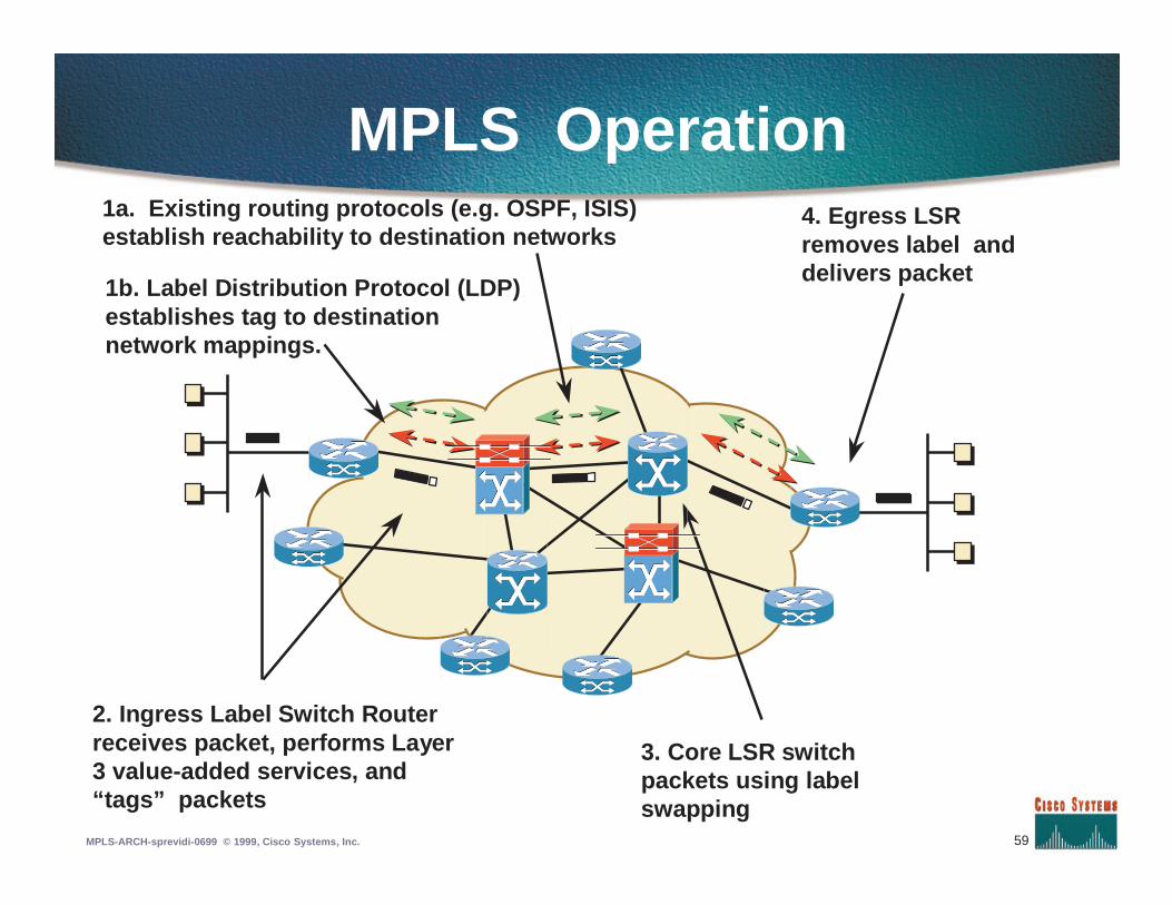
MPLS Operation1a. Existing routing protocols (e.g. OSPF, ISIS)establish reachability to destination networks
1b. Label Distribution Protocol (LDP)establishes tag to destinationnetwork mappings.
2. Ingress Label Switch Routerreceives packet, performs Layer3 value-added services, and“tags” packets
3. Core LSR switchpackets using labelswapping
4. Egress LSRremoves label anddelivers packet
60MPLS-ARCH-sprevidi-0699 © 1999, Cisco Systems, Inc.
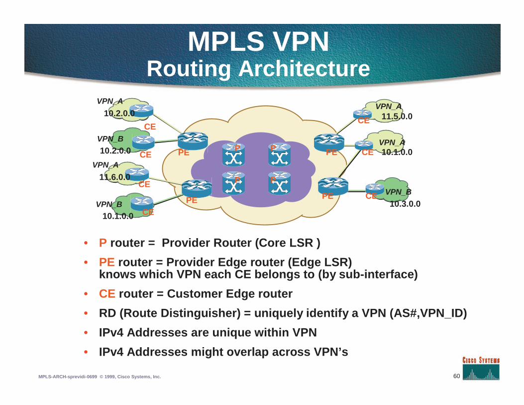
MPLS VPNRouting Architecture
• P router = Provider Router (Core LSR )
• PE router = Provider Edge router (Edge LSR)knows which VPN each CE belongs to (by sub-interface)
• CE router = Customer Edge router
• RD (Route Distinguisher) = uniquely identify a VPN (AS#,VPN_ID)
• IPv4 Addresses are unique within VPN
• IPv4 Addresses might overlap across VPN’s
VPN_A
VPN_A
VPN_B
10.3.0.0
10.1.0.0
11.5.0.0
P P
PP PE
PE CE
CE
CEVPN_A
VPN_B
VPN_B
10.1.0.0
10.2.0.0
11.6.0.0
CEPE
PECE
CE
VPN_A
10.2.0.0
CE
61MPLS-ARCH-sprevidi-0699 © 1999, Cisco Systems, Inc.
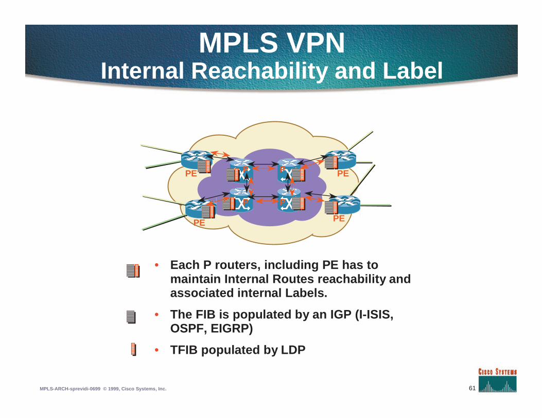
MPLS VPNInternal Reachability and Label
• Each P routers, including PE has tomaintain Internal Routes reachability andassociated internal Labels.
• The FIB is populated by an IGP (I-ISIS,OSPF, EIGRP)
• TFIB populated by LDP
PE
PE
P P
PP PE
PE
62MPLS-ARCH-sprevidi-0699 © 1999, Cisco Systems, Inc.
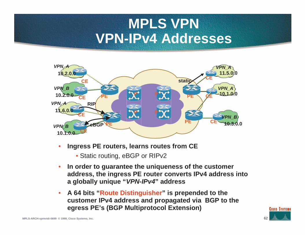
MPLS VPNVPN-IPv4 Addresses
VPN_A
VPN_A
VPN_B10.3.0.0
10.1.0.0
11.5.0.0
P P
PP PE
PE CE
CE
CE
• Ingress PE routers, learns routes from CE• Static routing, eBGP or RIPv2
• In order to guarantee the uniqueness of the customeraddress, the ingress PE router converts IPv4 address intoa globally unique “VPN-IPv4” address
• A 64 bits “Route DistinguisherRoute Distinguisher” is prepended to thecustomer IPv4 address and propagated via BGP to theegress PE’s (BGP Multiprotocol Extension)
VPN_A
VPN_B
VPN_B
10.1.0.0
10.2.0.0
11.6.0.0
CEPE
PECE
CE
VPN_A
10.2.0.0
CE
eBGP
static
RIP
63MPLS-ARCH-sprevidi-0699 © 1999, Cisco Systems, Inc.
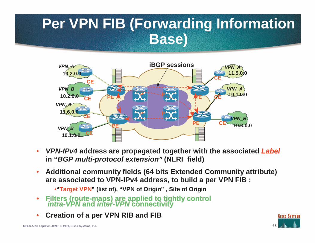
Per VPN FIB (Forwarding InformationBase)
VPN_A
VPN_A
VPN_B
10.3.0.0
10.1.0.0
11.5.0.0
P P
PP PE
PE CE
CE
CE
VPN_A
VPN_B
VPN_B
10.1.0.0
10.2.0.0
11.6.0.0
CEPE
PECE
CE
VPN_A
10.2.0.0
CE
• VPN-IPv4 address are propagated together with the associated LabelLabelin “BGP multi-protocol extension” (NLRI field)
• Additional community fields (64 bits Extended Community attribute)are associated to VPN-IPv4 address, to build a per VPN FIB :
•“Target VPN” (list of), “VPN of Origin” , Site of Origin
•• Filters (routeFilters (route--maps) are applied to tightly controlmaps) are applied to tightly controlintraintra--VPNVPN andand interinter--VPNVPN connectivityconnectivity
• Creation of a per VPN RIB and FIB
iBGP sessions
64MPLS-ARCH-sprevidi-0699 © 1999, Cisco Systems, Inc.
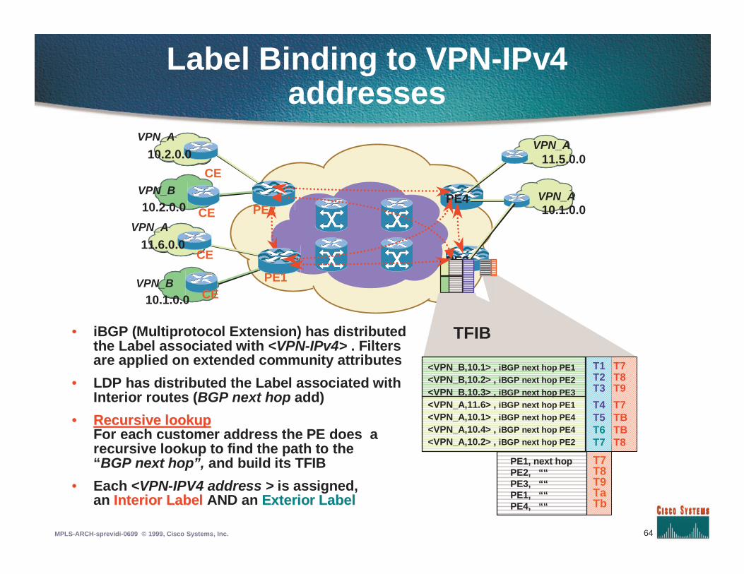
Label Binding to VPN-IPv4addresses
VPN_A
VPN_A
10.1.0.0
11.5.0.0
PE3
PE4
• iBGP (Multiprotocol Extension) has distributedthe Label associated with <VPN-IPv4> . Filtersare applied on extended community attributes
• LDP has distributed the Label associated withInterior routes (BGP next hop add)
•• Recursive lookupRecursive lookupFor each customer address the PE does arecursive lookup to find the path to the“BGP next hop”, and build its TFIB
• Each <VPN-IPV4 address > is assigned,an Interior LabelInterior Label AND an Exterior LabelExterior Label
PE1, next hopPE2, ““PE3, ““PE1, ““PE4, ““
T7T8T9TaTb
TFIB
VPN_A
VPN_B
VPN_B
10.1.0.0
10.2.0.0
11.6.0.0
CEPE1
PE2CE
CE
VPN_A
10.2.0.0
CE
<VPN_B,10.1> , iBGP next hop PE1<VPN_B,10.2> , iBGP next hop PE2<VPN_B,10.3> , iBGP next hop PE3<VPN_A,11.6> , iBGP next hop PE1<VPN_A,10.1> , iBGP next hop PE4<VPN_A,10.4> , iBGP next hop PE4<VPN_A,10.2> , iBGP next hop PE2
T1 T7T2 T8T3 T9
T4 T7T5 TBT6 TBT7 T8
65MPLS-ARCH-sprevidi-0699 © 1999, Cisco Systems, Inc.
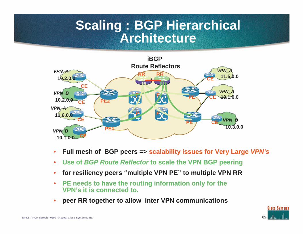
Scaling : BGP HierarchicalArchitecture
• Full mesh of BGP peers => scalability issues for Very Largescalability issues for Very Large VPN’sVPN’s
•• Use ofUse of BGP Route ReflectorBGP Route Reflector to scale the VPN BGP peeringto scale the VPN BGP peering
• for resiliency peers “multiple VPN PE” to multiple VPN RR
•• PE needs to have the routing information only for thePE needs to have the routing information only for theVPN’sVPN’s it is connected to.it is connected to.
• peer RR together to allow inter VPN communications
VPN_A
VPN_A
VPN_B
10.3.0.0
10.1.0.0
11.5.0.0
P P
PP PE
PE CE
CE
CE
RR RR
iBGPRoute Reflectors
VPN_A
VPN_B
VPN_B
10.1.0.0
10.2.0.0
11.6.0.0
CEPE1
PE2CE
CE
VPN_A
10.2.0.0
CE
66MPLS-ARCH-sprevidi-0699 © 1999, Cisco Systems, Inc.
T1 T7T2 T8T3 T9T4 T7T5 TBT6 TBT7 T8
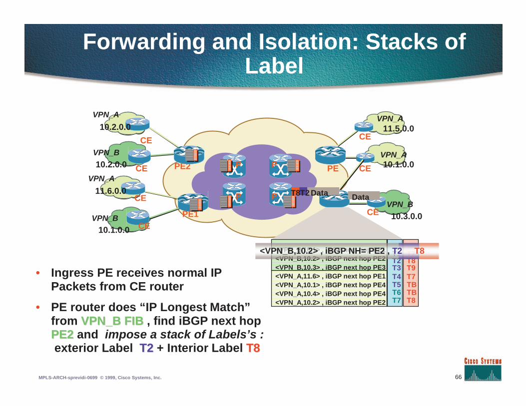
Forwarding and Isolation: Stacks ofLabel
VPN_A
VPN_A
VPN_B
10.3.0.0
10.1.0.0
11.5.0.0
P P
PP PE
CE
CE
CE
Data
<VPN_B,10.1> , iBGP next hop PE1<VPN_B,10.2> , iBGP next hop PE2<VPN_B,10.3> , iBGP next hop PE3<VPN_A,11.6> , iBGP next hop PE1<VPN_A,10.1> , iBGP next hop PE4<VPN_A,10.4> , iBGP next hop PE4<VPN_A,10.2> , iBGP next hop PE2
<VPN_B,10.2> , iBGP NH= PE2 , T2 T8
• Ingress PE receives normal IPPackets from CE router
• PE router does “IP Longest Match”from VPN_B FIBVPN_B FIB , find iBGP next hopPE2PE2 and impose a stack of Labels’s :exterior Label T2T2 + Interior Label T8T8
DataT8T2
VPN_A
VPN_B
VPN_B
10.1.0.0
10.2.0.0
11.6.0.0
CEPE1
PE2CE
CE
VPN_A
10.2.0.0
CE
67MPLS-ARCH-sprevidi-0699 © 1999, Cisco Systems, Inc.
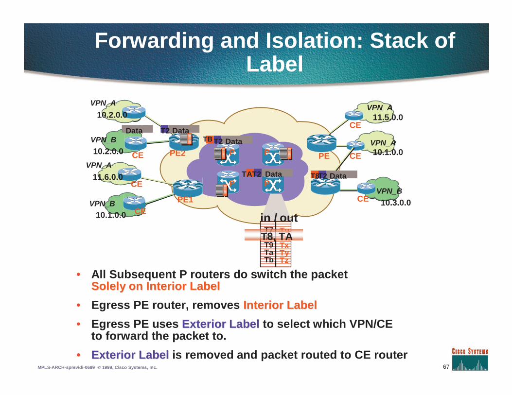
Forwarding and Isolation: Stack ofLabel
VPN_A
VPN_A
VPN_B
10.3.0.0
10.1.0.0
11.5.0.0
P P
PP PE
CE
CE
CE
T7T8T9TaTb
TuTwTxTyTz
T8, TA
T2 DataT8Data
T2 DataTB
outin /
• All Subsequent P routers do switch the packetSolely on Interior LabelSolely on Interior Label
• Egress PE router, removes Interior LabelInterior Label
• Egress PE uses Exterior LabelExterior Label to select which VPN/CEto forward the packet to.
•• Exterior LabelExterior Label is removed and packet routed to CE router
VPN_A
VPN_B
VPN_B
10.1.0.0
10.2.0.0
11.6.0.0
CEPE1
PE2CE
CE
VPN_A
10.2.0.0
CE T2 DataData
TAT2
68MPLS-ARCH-sprevidi-0699 © 1999, Cisco Systems, Inc.
VPN_A
VPN_B
VPN_A
VPN_A
VPN_B
VPN_B
10.1.0.0
10.2.0.0
10.3.0.0
10.1.0.0
11.5.0.0
11.6.0.0
CEPE
PE PE
CE
CE
CE
CE
CE
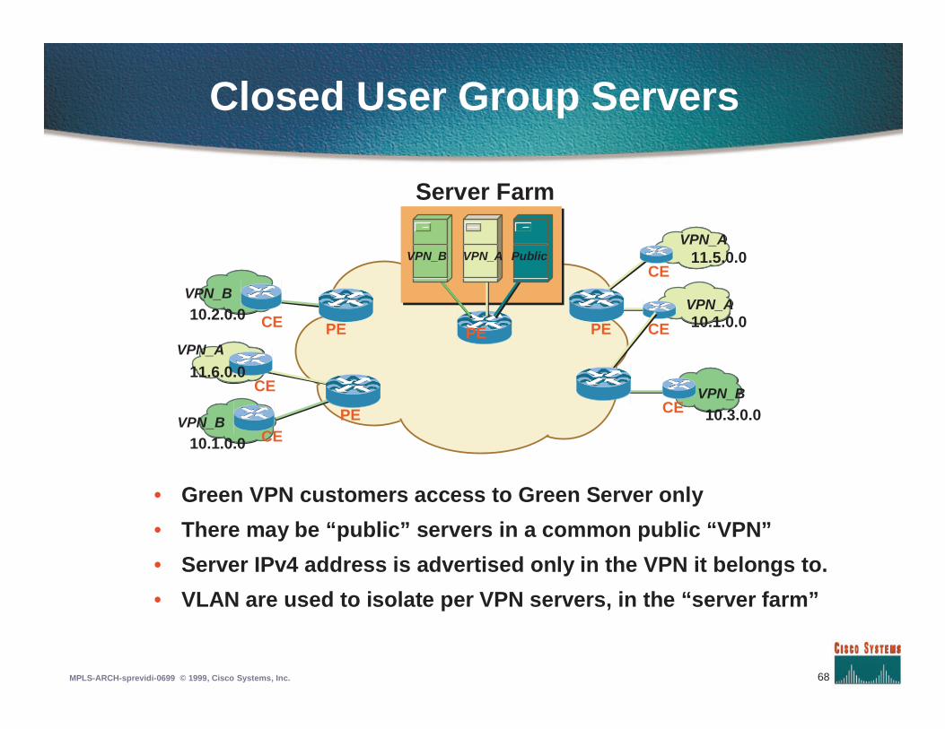
Closed User Group Servers
• Green VPN customers access to Green Server only
• There may be “public” servers in a common public “VPN”
• Server IPv4 address is advertised only in the VPN it belongs to.
• VLAN are used to isolate per VPN servers, in the “server farm”
PE
Server Farm
VPN_B PublicVPN_A
69MPLS-ARCH-sprevidi-0699 © 1999, Cisco Systems, Inc.
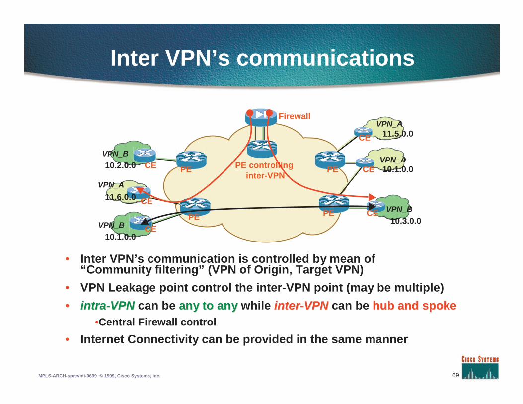
Inter VPN’s communications
VPN_A
VPN_B
VPN_A
VPN_A
VPN_B
VPN_B
10.1.0.0
10.2.0.0
10.3.0.0
10.1.0.0
11.5.0.0
11.6.0.0
CEPE
PE PE
PE CE
CE
CE
CE
CE
• Inter VPN’s communication is controlled by mean of“Community filtering” (VPN of Origin, Target VPN)
• VPN Leakage point control the inter-VPN point (may be multiple)
•• intraintra--VPNVPN can be any to anyany to any while interinter--VPNVPN can be hub and spokehub and spoke•Central Firewall control
• Internet Connectivity can be provided in the same manner
PE controllinginter-VPN
Firewall
70MPLS-ARCH-sprevidi-0699 © 1999, Cisco Systems, Inc.
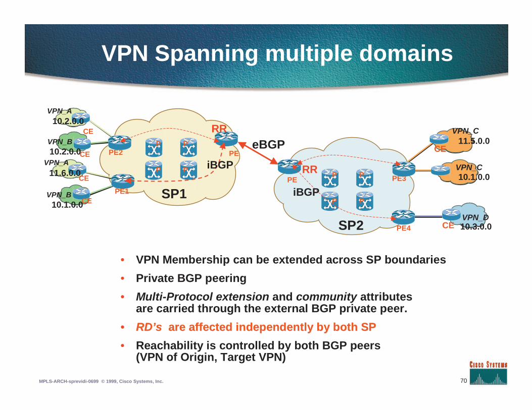
VPN Spanning multiple domains
• VPN Membership can be extended across SP boundaries
• Private BGP peering
• Multi-Protocol extension and community attributesare carried through the external BGP private peer.
•• RD’sRD’s are affected independently by both SPare affected independently by both SP
• Reachability is controlled by both BGP peers(VPN of Origin, Target VPN)
P P
PPPE
VPN_A
VPN_B
VPN_B
10.1.0.0
10.2.0.0
11.6.0.0
CEPE1
PE2CE
CE
VPN_A10.2.0.0
CE
P P
PPPE
eBGP
PE3
SP1
SP2
VPN_C
VPN_D10.3.0.0
11.5.0.0
CE
CE
PE4
10.1.0.0VPN_CiBGP
iBGP
RR
RR
71MPLS-ARCH-sprevidi-0699 © 1999, Cisco Systems, Inc.
Agenda
• Introduction to MPLS
• Label forwarding
• Label Distribution Protocol
• Traffic Engineering
• MPLS VPN
• MPLS QoS
72MPLS-ARCH-sprevidi-0699 © 1999, Cisco Systems, Inc.
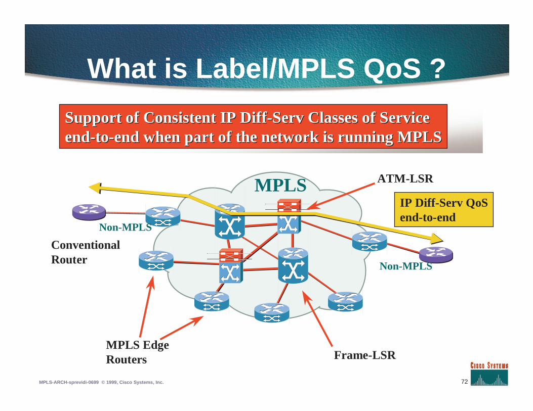
What is Label/MPLS QoS ?
ConventionalRouter
MPLS EdgeRouters
ATM-LSR
Frame-LSR
MPLS
Non-MPLS
Non-MPLS
IP Diff-Serv QoSend-to-end
Support of Consistent IP DiffSupport of Consistent IP Diff--Serv Classes of ServiceServ Classes of Serviceendend--toto--end when part of the network is running MPLSend when part of the network is running MPLS
73MPLS-ARCH-sprevidi-0699 © 1999, Cisco Systems, Inc.
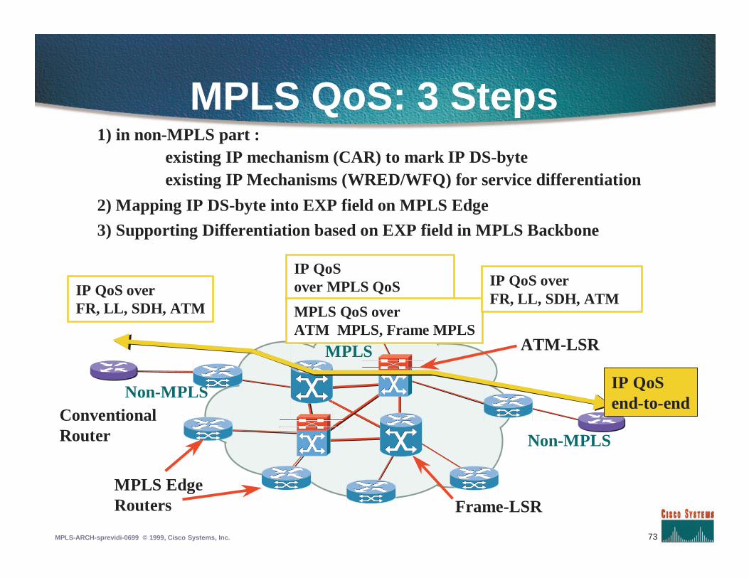
MPLS QoS: 3 Steps
ConventionalRouter
MPLS EdgeRouters
ATM-LSR
Frame-LSR
MPLS
Non-MPLS
Non-MPLS
IP QoSend-to-end
IP QoS overFR, LL, SDH, ATM
IP QoSover MPLS QoS
MPLS QoS overATM MPLS, Frame MPLS
IP QoS overFR, LL, SDH, ATM
1) in non-MPLS part :existing IP mechanism (CAR) to mark IP DS-byteexisting IP Mechanisms (WRED/WFQ) for service differentiation
2) Mapping IP DS-byte into EXP field on MPLS Edge
3) Supporting Differentiation based on EXP field in MPLS Backbone
74MPLS-ARCH-sprevidi-0699 © 1999, Cisco Systems, Inc.
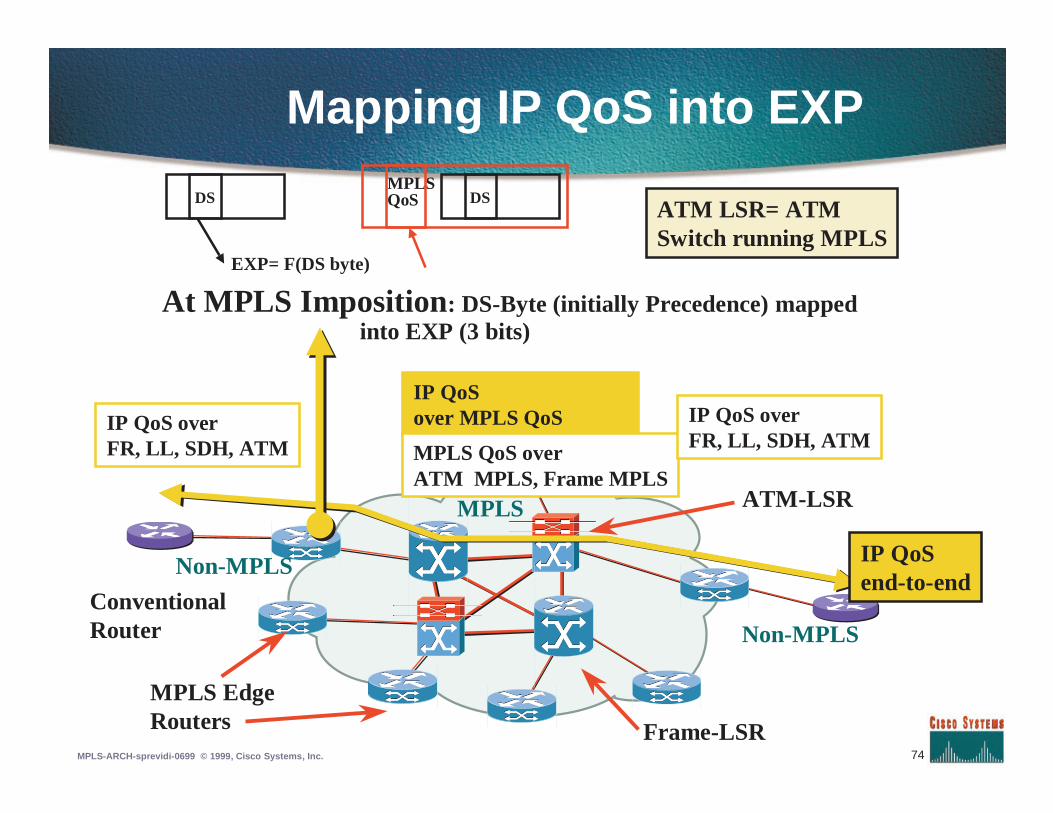
Mapping IP QoS into EXP
ConventionalRouter
MPLS EdgeRouters
ATM-LSR
Frame-LSR
MPLS
Non-MPLS
Non-MPLS
IP QoSend-to-end
IP QoS overFR, LL, SDH, ATM
IP QoSover MPLS QoS
MPLS QoS overATM MPLS, Frame MPLS
IP QoS overFR, LL, SDH, ATM
DSMPLSQoS DS
EXP= F(DS byte)
At MPLS Imposition: DS-Byte (initially Precedence) mappedinto EXP (3 bits)
ATM LSR= ATMSwitch running MPLS
75MPLS-ARCH-sprevidi-0699 © 1999, Cisco Systems, Inc.
Supporting MPLS QoS over non-ATMMPLS
• On MPLS Frame Interface (ie non-ATM),it’s simple:
• Every MPLS packet has explicit indication of QoS in MPLSHeader
• Use EXP field to trigger Selective Scheduling (WFQ) andSelective Discard (WRED) ; exactly like use of IP DS-bytein non-MPLS
• Net result is end-to-end QoSindistinguishable from non-MPLS network

76MPLS-ARCH-sprevidi-0699 © 1999, Cisco Systems, Inc.
Supporting MPLS QoS over ATMMPLS
• Main challenges:•No QoS field in ATM cell header
•No WRED in switches
• Two modes:•Single `VC’ ABR
•Multi-`VC’ TBR(closer to Frame QoS)
•Each has advantages and drawbacks
TBR= Tag Bit RateTBR= Tag Bit RateATM Service Category better suited to IPATM Service Category better suited to IP
77MPLS-ARCH-sprevidi-0699 © 1999, Cisco Systems, Inc.
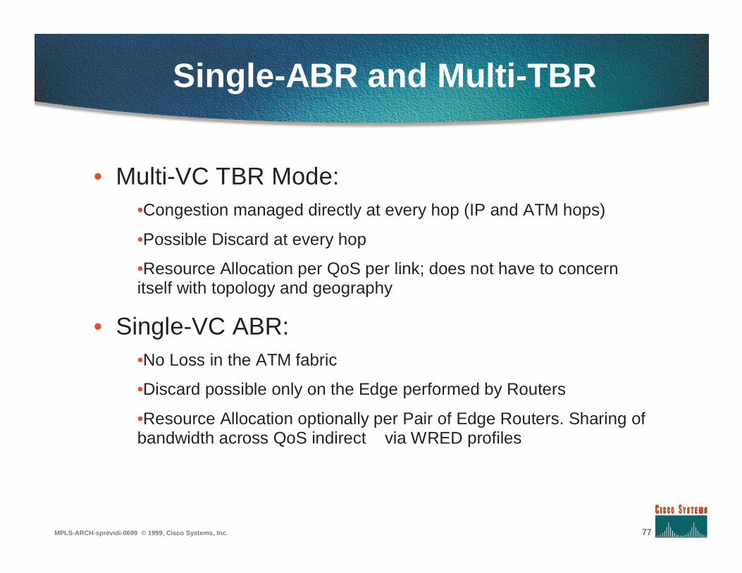
Single-ABR and Multi-TBR
• Multi-VC TBR Mode:•Congestion managed directly at every hop (IP and ATM hops)
•Possible Discard at every hop
•Resource Allocation per QoS per link; does not have to concernitself with topology and geography
• Single-VC ABR:•No Loss in the ATM fabric
•Discard possible only on the Edge performed by Routers
•Resource Allocation optionally per Pair of Edge Routers. Sharing ofbandwidth across QoS indirect via WRED profiles