Embed Size (px)
Citation preview

MPLS
Multi-Protocol Label Switching

© 2016, D.I. Lindner MPLS v6.1 2
Agenda
• Review ATM• IP over WAN Problems (Traditional Approach) • MPLS Principles• Label Distribution Methods• MPLS Details (Cisco)• RFCs

© 2016, D.I. Lindner MPLS v6.1 3
ATM Principles
• ATM– Asynchronous Transfer Mode– Based on asynchronous TDM
• Hence buffering and address information is necessary• Variable delay (!)
• Cell switching technology– Based on store-and-forward of cells– Connection-oriented type of service with PVC and SVC– But no error recovery (!)
• ATM cell– Small packet with constant length
– 53 bytes long (5 bytes header + 48 bytes data)

© 2016, D.I. Lindner MPLS v6.1 4
8 7 6 5 4 3 2 1
1
2
3
4
5
UNI Header
8 7 6 5 4 3 2 1
1
2
3
4
5
NNI Header
GFC VPI
VPI VCI
VCI
VCI PT CLP
HEC
VPI VPI
VPI VCI
VCI
VCI PT CLP
HEC
Cell Format
• Two slightly different formats– UNI … 8 bits for VPI– NNI … 12 bits for VPI

© 2016, D.I. Lindner MPLS v6.1 5
ATM Network: Physical Topology
UNI
ATM DTEATM DTE
ATM DTE
ATM DTE
ATM DCEATM DCE
ATM DCE
ATM DCE
NNI
UNI + NNI defined

© 2016, D.I. Lindner MPLS v6.1 6
ATM Network: Virtual CircuitsLocal Connection Identifiers and Logical Channels
1/2531/452
3/2533/2003/452
9/99
100/6
3/2
5/88
1/123
1/321
3/2
66/6
IN OUT9/99 66/6
Virtual Path Identifier (VPI)Virtual Channel Identifier (VCI)
VPI VCIVPI/VCI numbers(local significance !!!)
UNI
UNI
NNI
1/455

© 2016, D.I. Lindner MPLS v6.1 7
1 2
43
I1
ATM Switching Tables
I1: 0/88 O2: 0/77
from to
I4: 0/99 O2: 0/44
from to
I1: 0/77 O2: 0/99I4: 0/77 O3: 4/88
from to
A
O3I1
O2 I4
O2
I4O3
I1O3
I1: 0/50 O3: 0/77
from to
B
CD
I1: 4/88 O3: 2/99
from to
I1
O2
Switching Tableof ATM Switch 2
ATM DTE ATM DTE
ATM DTEATM DTE
© 2016, D.I. Lindner MPLS v6.1 8
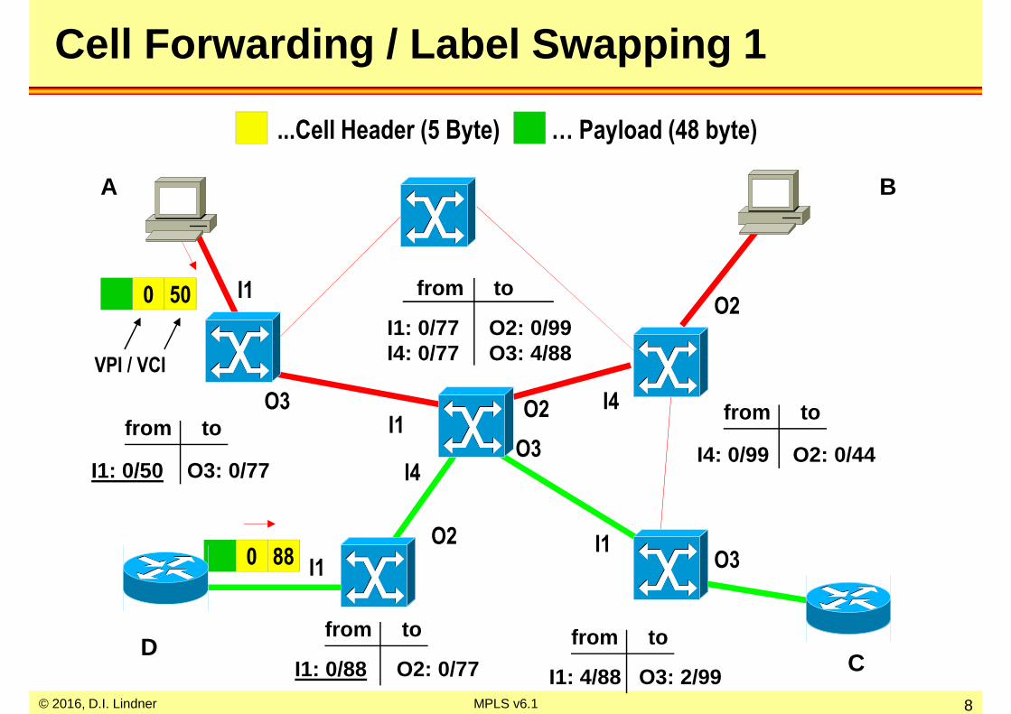
Cell Forwarding / Label Swapping 1
I1
I1: 0/88 O2: 0/77
from to
I4: 0/99 O2: 0/44
from to
I1: 0/77 O2: 0/99I4: 0/77 O3: 4/88
from to
A
O3I1
O2 I4
O2
I4O3
I1O3
I1: 0/50 O3: 0/77
from to
B
CD
I1: 4/88 O3: 2/99
from to
I1
O2
...Cell Header (5 Byte) … Payload (48 byte)
0 50
VPI / VCI
0 88

© 2016, D.I. Lindner MPLS v6.1 9
Cell Forwarding / Label Swapping 2
1 2
43
I1
I1: 0/88 O2: 0/77
from to
I4: 0/99 O2: 0/44
from to
I1: 0/77 O2: 0/99I4: 0/77 O3: 4/88
from to
A
O3I1
O2 I4
O2
I4O3
I1O3
I1: 0/50 O3: 0/77
from to
B
CD
I1: 4/88 O3: 2/99
from to
I1
O2
0 77
0 77
© 2016, D.I. Lindner MPLS v6.1 10
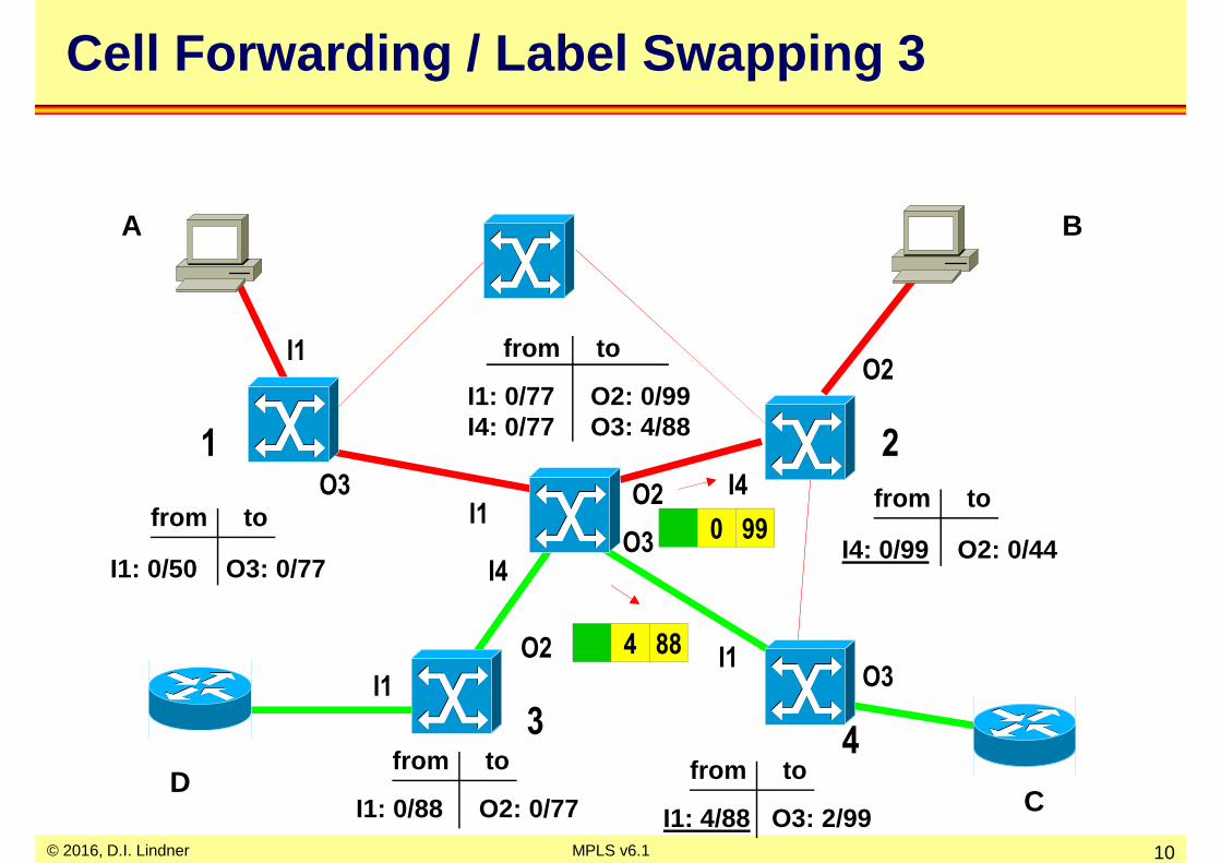
Cell Forwarding / Label Swapping 3
1 2
43
I1
I1: 0/88 O2: 0/77
from to
I4: 0/99 O2: 0/44
from to
I1: 0/77 O2: 0/99I4: 0/77 O3: 4/88
from to
A
O3I1
O2 I4
O2
I4O3
I1O3
I1: 0/50 O3: 0/77
from to
B
CD
I1: 4/88 O3: 2/99
from to
I1
O2
0 99
4 88
© 2016, D.I. Lindner MPLS v6.1 11
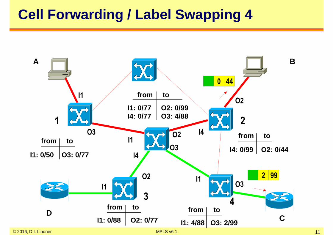
Cell Forwarding / Label Swapping 4
1 2
43
I1
I1: 0/88 O2: 0/77
from to
I4: 0/99 O2: 0/44
from to
I1: 0/77 O2: 0/99I4: 0/77 O3: 4/88
from to
A
O3I1
O2 I4
O2
I4O3
I1O3
I1: 0/50 O3: 0/77
from to
B
CD
I1: 4/88 O3: 2/99
from to
I1
O2
0 44
2 99
© 2016, D.I. Lindner MPLS v6.1 12
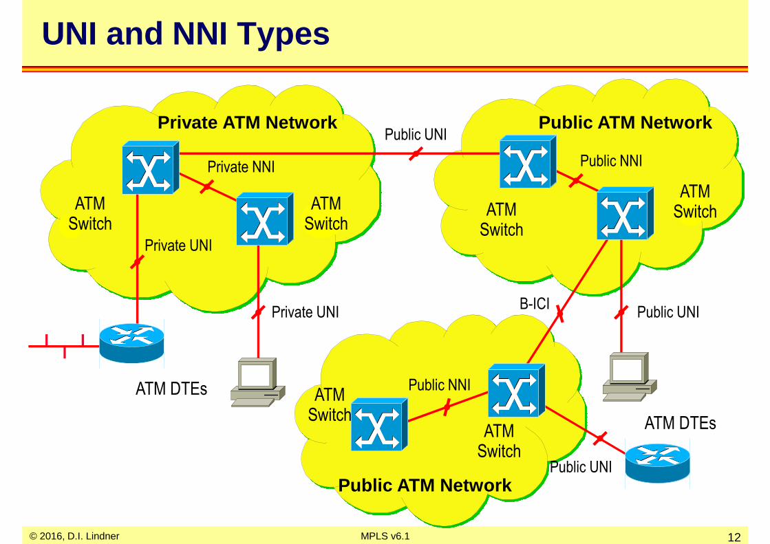
Private UNI
Private NNI
Private ATM Network
ATM DTEs
Private UNI
ATMSwitch
ATMSwitch
Public NNI
ATMSwitch
Public ATM Network
ATMSwitch
Public UNI
Public UNI
ATMSwitch
ATMSwitch
Public NNI
Public ATM Network
B-ICI
Public UNI
ATM DTEs
UNI and NNI Types

© 2016, D.I. Lindner MPLS v6.1 13
Control Plane < -> User Plane
ATM-DTE
Physical access link
ATM-DCE
Virtual circuitfor user data
Virtual circuitfor signaling / ILMI / routing
User plane describes protocols used between ATM DTEs on transport pipe
Control plane describes protocolsused between ATM DTE and ATM DCE
or between ATM DCE and ATM DCE
VPI/VCI = 0/5(e.g. Q.2931 signaling)
ATM-DCE
VPI/VCI = 0/18(e.g. PNNI Routing)
ATM-DTE
VPI/VCI = 0/5(e.g. PNNI Signaling)

© 2016, D.I. Lindner MPLS v6.1 14
Service Classes
GuaranteedService
“Bandwidthon Demand”
“Best Effort”Service
CBRConstant Bit RateCircuit Emulation, Voice
VBRVariable Bit RateFull Traffic CharacterizationReal-Time VBR and Non Real-Time VBR
UBRUnspecified Bit RateNo Guarantees, “Send and Pray”
ABR
Available Bit RateNo Quantitative Guarantees, butCongestion Control Feedback assures low cell loss

© 2016, D.I. Lindner MPLS v6.1 15
Traffic Contract per Service Class
• Specified for each service class
CLR
CTD
CDV
MBS
=
=
=
=
Cell Loss Ratio
Cell Transfer Delay
Cell Delay Variation
Maximum Burst Size
PCR
CDVT
SCR
MCR
=
=
=
=
Peak Cell Rate
CDV Tolerance
Sustainable CR
Minimum CR
CLR Specified Optional Unspecified
max CTD & ptp CDV Specified Unspecified Unspecified
ATTRIBUTE CBR rt-VBR nrt-VBR ABR UBR
PCR & CDVT Specified Specified
SCR, MBS, CDVT Specifiedn/a n/a
MCR n/a Specified n/a

© 2016, D.I. Lindner MPLS v6.1 16
ATM as an Intelligent Bandwidth Management System
UBR burst
Available
Trunk BW
(e.g. 622Mb/s)
ΣΣΣΣ PCR (CBR)
ΣΣΣΣ SCR (VBR)
ΣΣΣΣ PCR (VBR)
ABR burst
ΣΣΣΣ MCR (ABR)
VBR average
VBR burst
CBR constant
+
+
+
ABR average

© 2016, D.I. Lindner MPLS v6.1 17
Yes/No
Connect to B
NNIUNI
NNI
Yes/No
Connect to B
UNI
A
ATM End
System
B
ATM End
System
ATM Switches
Give me this Bandwidth
and QoS to B
OK
ATM Goal: Bandwidth on Demand with QoS Guarantees

© 2016, D.I. Lindner MPLS v6.1 18
ATM Routing in Private ATM Networks
• PNNI is based on Link -State technique– like OSPF
• Topology database– Every switch maintains a database representing the states
of the links and the switches
– Extension to link state routing !!!– Announce status of node (!) as well as status of links
• Contains dynamic parameters like delay, available cell rate, etc. versus static-only parameters of OSPF (link up/down, node up/down, nominal bandwidth of link)
• Path determination based on metrics– Much more complex than with standard routing protocols
because of ATM-inherent QoS support

© 2016, D.I. Lindner MPLS v6.1 19
3.) Is it likely that path will deliver expected QoS?
2. Yes/No
UNI/NNI
1. Support this QoS locally?
CAC
GCAC
PNNI Routing
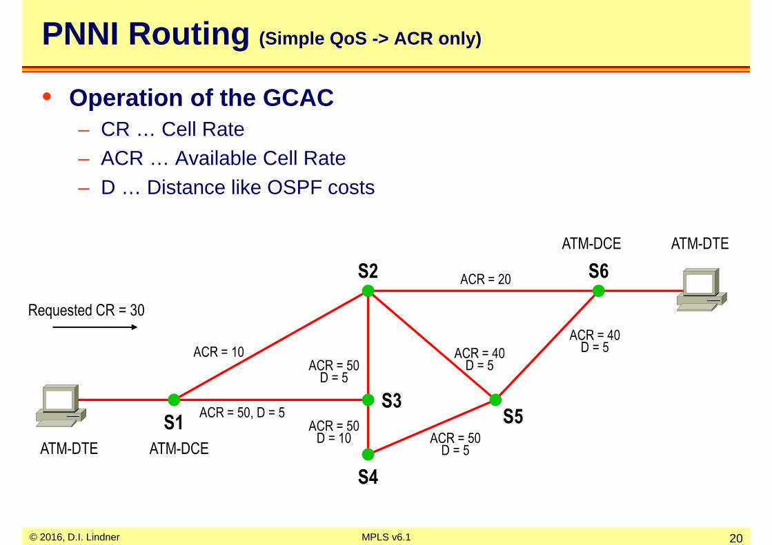
• Generic Connection Admission Control (GCAC)– Used by the source switch to select a path through the network– Calculates the expected CAC (Connection Admission Control)
behavior of another node
© 2016, D.I. Lindner MPLS v6.1 20
ACR = 50, D = 5S1
S3
S2
ACR = 10ACR = 50
D = 5
ACR = 40D = 5
ACR = 20
ACR = 50D = 10 ACR = 50
D = 5
S4
S5
S6
ACR = 40D = 5
Requested CR = 30
PNNI Routing (Simple QoS -> ACR only)
• Operation of the GCAC– CR … Cell Rate– ACR … Available Cell Rate– D … Distance like OSPF costs
ATM-DTE ATM-DCE
ATM-DCE ATM-DTE

© 2016, D.I. Lindner MPLS v6.1 21
ACR = 50, D = 5S1
S3
S2
ACR = 10ACR = 50
D = 5
ACR = 40D = 5
ACR = 20
ACR = 50D = 10 ACR = 50
D = 5
S4
S5
S6
ACR = 40D = 5
PNNI Routing
• Operation of the GCAC– 1) Links not supporting requested CR are eliminated ->
• Metric component -> ACR value used
Requested CR = 30
© 2016, D.I. Lindner MPLS v6.1 22
ACR = 50, D = 5S1
S3
S2
ACR = 10ACR = 50
D = 5
ACR = 40D = 5
ACR = 20
ACR = 50D = 10 ACR = 50
D = 5
S4
S5
S6
ACR = 40D = 5
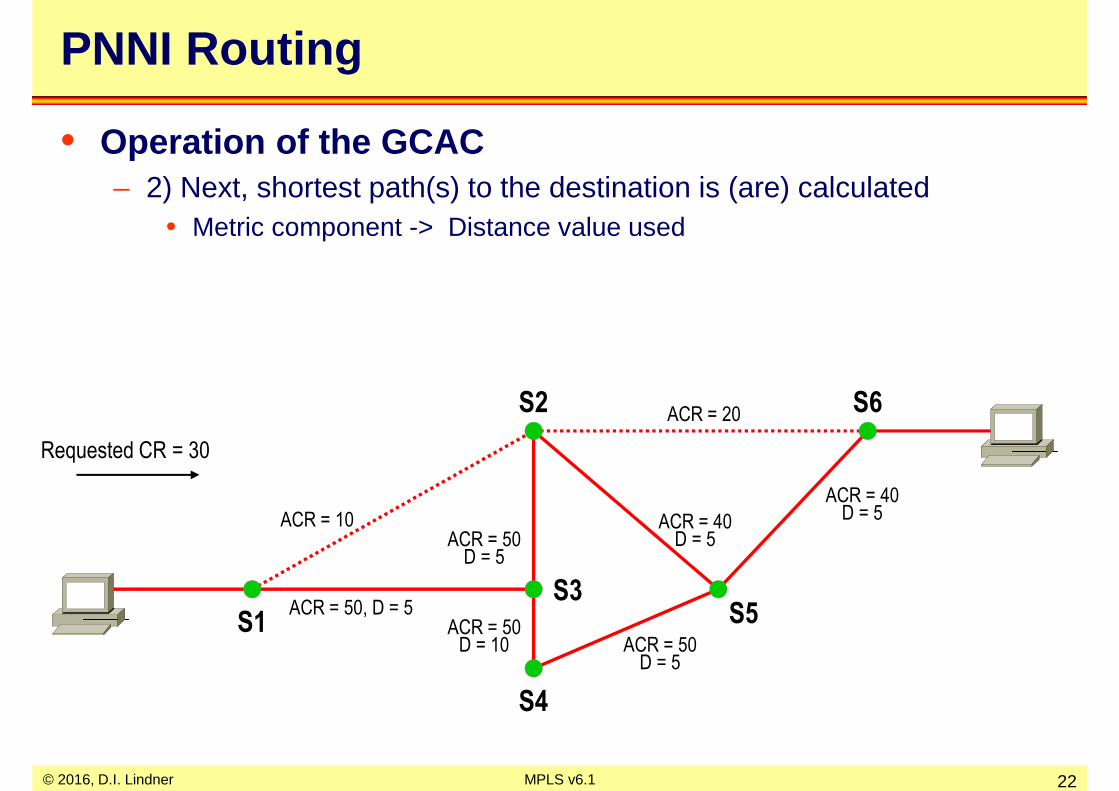
PNNI Routing
• Operation of the GCAC– 2) Next, shortest path(s) to the destination is (are) calculated
• Metric component -> Distance value used
Requested CR = 30

© 2016, D.I. Lindner MPLS v6.1 23
ACR = 50, D = 5S1
S3
S2
ACR = 10ACR = 50
D = 5
ACR = 40D = 5
ACR = 20
ACR = 50D = 10 ACR = 50
D = 5
S4
S5
S6
ACR = 40D = 5
requested ACR = 30
PNNI Routing
• Operation of the GCAC– 3) One path is chosen and source node S1 constructs a Designated
Transit List (DTL) -> source routing -->• Describes the complete route to the destination
Requested CR = 30

© 2016, D.I. Lindner MPLS v6.1 24
ACR = 50, D = 5S1
S3
S2
ACR = 10ACR = 50
D = 5
ACR = 40D = 5
ACR = 20
ACR = 50D = 10 ACR = 50
D = 5
S4
S5
S6
ACR = 40D = 5
requested ACR = 30
PNNI Routing - Source Routing
• Operation of the GCAC– 4) DTL is inserted into signaling request and moved on to next switch– 5) After receipt next switch perform local CAC
• 5a) if ok -> pass PNNI signaling message on to next switch of DTL
– 6a) finally signaling request will reach destination ATM-DTE -> VC ok
PNNI Signaling with DTL list

© 2016, D.I. Lindner MPLS v6.1 25
ACR = 50, D = 5S1
S3
S2
ACR = 10ACR = 50
D = 5
ACR = 40D = 5
ACR = 20
ACR = 50D = 10 ACR = 50
D = 5
S4
S5
S6
ACR = 40D = 5
requested ACR = 30
PNNI Routing - Crankbank
• Operation of the GCAC– 5) After receipt next switch (S2) perform local CAC
• 5b) if nok -> return PNNI signaling message to originator of DTL
– 6b) S1 will construct alternate source route
PNNI Signaling with DTL list S2 cannot fulfill requirements on trunk to S5
Crankbank to S1

© 2016, D.I. Lindner MPLS v6.1 26
ACR = 50, D = 5S1
S3
S2
ACR = 10ACR = 50
D = 5
ACR = 40D = 5
ACR = 20
ACR = 50D = 10 ACR = 50
D = 5
S4
S5
S6
ACR = 40D = 5
requested ACR = 30
PNNI Routing - New Trial
• Operation after Crankbank– 7b) The other possible path is chosen - source node constructs again
a new Designated Transit List (DTL)
Requested CR = 30

© 2016, D.I. Lindner MPLS v6.1 27
ACR = 50, D = 5S1
S3
S2
ACR = 10ACR = 50
D = 5
ACR = 40D = 5
ACR = 20
ACR = 50D = 10 ACR = 50
D = 5
S4
S5
S6
ACR = 40D = 5
requested ACR = 30
PNNI Routing - Source Routing
• Operation of the GCAC– 8b) DTL is inserted into signaling request– 9b) After receipt next switch perform local CAC
• if ok -> pass PNNI signaling message on to next switch of DTL
– 10b) finally signaling request will reach destination ATM-DTE -> VC ok
PNNI Signaling with DTL list

© 2016, D.I. Lindner MPLS v6.1 28
Agenda
• Review ATM• IP over WAN Problems (Traditional Approach)
– Introduction, Base Problem 1• Non-NBMA-View• NMBA-View
– Base Problem 2, Solution
• MPLS Principles• Label Distribution Methods• MPLS Details (Cisco)• RFCs

© 2016, D.I. Lindner MPLS v6.1 29
IP Overlay Model - Scalability
• Base problem Nr.1– IP routing separated from ATM routing because of the
normal IP overlay model– no exchange of routing information between IP and ATM
world– leads to scalability and performance problems
• many peers, configuration overhead, duplicate broadcasts
– note: • IP system requests virtual circuits from the ATM network• ATM virtual circuits are established according to PNNI routing• virtual circuits are treated by IP as normal point-to-point links• IP routing messages are transported via this point-to-point links to
discover IP neighbors and IP network topology
© 2016, D.I. Lindner MPLS v6.1 30
IP Performance
• Base problem Nr.2– IP forwarding is slow compared to ATM cell forwarding
• IP routing paradigm• hop-by-hop routing with (recursive) IP routing table lookup, IP TTL
decrement and IP checksum computing• destination based routing (large tables in the core of the Internet)
– Load balancing• in a stable network all IP datagram's will follow the same path
(least cost routing versus ATM´s QoS routing)
– QoS (Quality of Service)• IP is connectionless packet switching (best-effort delivery versus
ATM´s guarantees)
– VPN (Virtual Private Networks)• ATM VC´s have a natural closed user group (=VPN) behavior
© 2016, D.I. Lindner MPLS v6.1 31
Basic Ideas to Solve the Problems
• Make ATM topology visible to IP routing– to solve the scalability problems– a classical ATM switch gets IP router functionality
• Divide IP routing from IP forwarding– to solve the performance problems
– IP forwarding based on ATM´s label swapping paradigm (connection-oriented packet switching)
– IP routing based on classical IP routing protocols
• Combine best of both– forwarding based on ATM label swapping paradigm– routing done by traditional IP routing protocols

© 2016, D.I. Lindner MPLS v6.1 32
MPLS
• Several similar technologies were invented in the mid -1990s– IP Switching (Ipsilon)– Cell Switching Router (CSR, Toshiba)
– Tag Switching (Cisco)– Aggregated Route-Based IP Switching (ARIS, IBM)
• IETF merges these technologies– MPLS (Multi Protocol Label Switching)
• note: multiprotocol means that IP is just one possible protocol to be transported by a MPLS switched network
– RFC 3031

© 2016, D.I. Lindner MPLS v6.1 33
MPLS Building Blocks
MPLSTransport
MPLS VPN (Virtual Private Network)
MPLS Multicast
MPLS ATOM (Any Transport over MPLS)
MPLS TE (Traffic Engineering)
MPLS QoS (Quality of Service)
You always need this!MPLS Transport solves most of the mentioned problems(scalability / performance)
If you need "Advanced Features like VPN orMulticast support you optionally may choosefrom these building blocks riding on top of a MPLS Transport network

© 2016, D.I. Lindner MPLS v6.1 34
Agenda
• Review ATM• IP over WAN Problems (Traditional Approach)
– Introduction, Base Problem 1• Non-NBMA-View• NMBA-View
– Base Problem 2, Solution
• MPLS Principles• Label Distribution Methods• MPLS Details (Cisco)• RFCs

© 2016, D.I. Lindner MPLS v6.1 35
A Simple Physical Network ...
Physical wiring
© 2016, D.I. Lindner MPLS v6.1 36
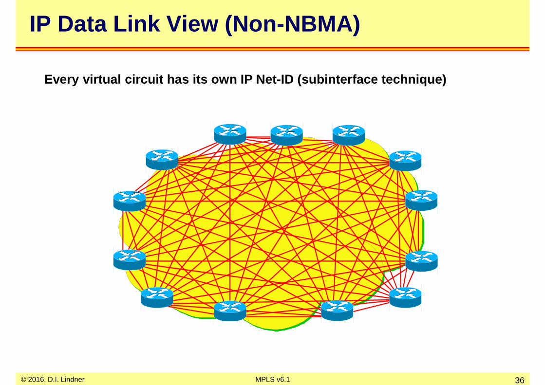
IP Data Link View (Non -NBMA)
Every virtual circuit has its own IP Net-ID (subint erface technique)

© 2016, D.I. Lindner MPLS v6.1 37
A Single Network Failure ...

© 2016, D.I. Lindner MPLS v6.1 38
Causes Loss of Multiple IP Router Peers !!!
© 2016, D.I. Lindner MPLS v6.1 39
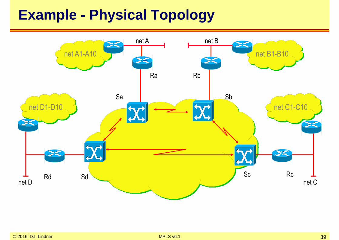
Example - Physical Topology
net A net B
net C
Ra Rb
Sa Sb
RcScnet D
SdRd
net C1-C10net D1-D10
net B1-B10net A1-A10

© 2016, D.I. Lindner MPLS v6.1 40
IP Connectivity through Full-mesh VC ´s
net A net B
net C
Ra Rb
Rcnet D
Rd
net C1-C10net D1-D10
net B1-B10net A1-A10

© 2016, D.I. Lindner MPLS v6.1 41
net C1-C10net D1-D10
net B1-B10net A1-A10
Static Routing/No Routing Broadcasts
static routing address resolution PVC address resolution SVC
net A via next hopRa Ra map VPI/VCI Rd � Ra Ra map ATM addr. Ra
net B via next hopRb Rb map VPI/VCI Rd � Rb Rb map ATM addr. Rb
net C via next hopRc Rc map VPI/VCI Rd � Rc Rc map ATM addr. Rc
every remote network listed here!
Configuration Router Rd
net A net B
net C
Ra Rb
Rcnet D
Rd

© 2016, D.I. Lindner MPLS v6.1 42
Dynamic Routing/Routing Broadcasts
dynamic routing on PVC address resolution PVC
VPI/VCI Rd � Ra broadcast Ra map VPI/VCI Rd � Ra
VPI/VCI Rd � Rb broadcast Rb map VPI/VCI Rd � Rb
VPI/VCI Rd � Rc broadcast Rc map VPI/VCI Rd � Rc
note: SVCs may be possible if Cisco neighbor command is specified for Cisco routing process because
no automatic neighbor discovery is possible in this case
Configuration Router Rd
net C1-C10net D1-D10
net B1-B10net A1-A10
net A net B
net C
Ra Rb
Rcnet D
Rd

© 2016, D.I. Lindner MPLS v6.1 43
Observations
• This clearly does not scale• Switch/router interaction needed
– peering model
• Without MPLS– Only outside routers are layer 3 neighbors– one ATM link failure causes multiple peer failures– routing traffic does not scale (number of peers)
• With MPLS– Inside MPLS switch is the layer 3 routing peer of an outside router– one ATM link failure causes one peer failure– highly improved routing traffic scalability

© 2016, D.I. Lindner MPLS v6.1 44
Agenda
• Review ATM• IP over WAN Problems (Traditional Approach)
– Introduction, Base Problem 1• Non-NBMA-View• NMBA-View
– Base Problem 2, Solution
• MPLS Principles• Label Distribution Methods• MPLS Details (Cisco)• RFCs

© 2016, D.I. Lindner MPLS v6.1 45
A Simple Physical Network ...
Physical wiring and NBMA behavior

© 2016, D.I. Lindner MPLS v6.1 46
IP Data Link View (NBMA)
Routers assume a LAN behavior because all interface s have the same IP Net-ID but LAN broadcasting to reach all ot hers is not possible
LIS … Logical IP Subnet
© 2016, D.I. Lindner MPLS v6.1 47
Some Solutions for the NBMA Problem
– ARP (Address Resolution Protocol) Server• keeps configuration overhead for address resolution small• but does not solve the routing issue (neighbor discovery and
duplicate routing broadcasts on a single wire)
– MARS/MCS (Multicast Address Resolution Server / Multicast Server)
• additional keeps configuration overhead for routing small• and does solve broadcast/multicast problem with either full mesh
of point-to-multipoint circuits or by usage of MCS server
– LANE (LAN Emulation = ATM VLAN´s)• simulates LAN behavior where address resolution and routing
broadcasts are not a problem
– All of them• require a lot of control virtual circuits (p-t-p and p-t-m) and SVC
support of the underlying ATM network

© 2016, D.I. Lindner MPLS v6.1 48
RFC 2225 Operation (Classical IP over ATM)
• ARP server for every LIS – multiple hops for communication between Logical IP Subnets
LIS1
ATM
Network
ARP ServerSubnet 1
ARP ServerSubnet 2LIS2

© 2016, D.I. Lindner MPLS v6.1 49
MARS/MCS Architecture
Server Control VC
CLIENT CLIENT
MCS
MCS
point-to-multipoint data VC
CLIENT
Control VC
Cluster Control
VC
CLIENTCLIENT
CLIENT
MARS

© 2016, D.I. Lindner MPLS v6.1 50
Data Direct (SVC -> VC on Demand)
BUSLECS
LES
LANE Connections

© 2016, D.I. Lindner MPLS v6.1 51
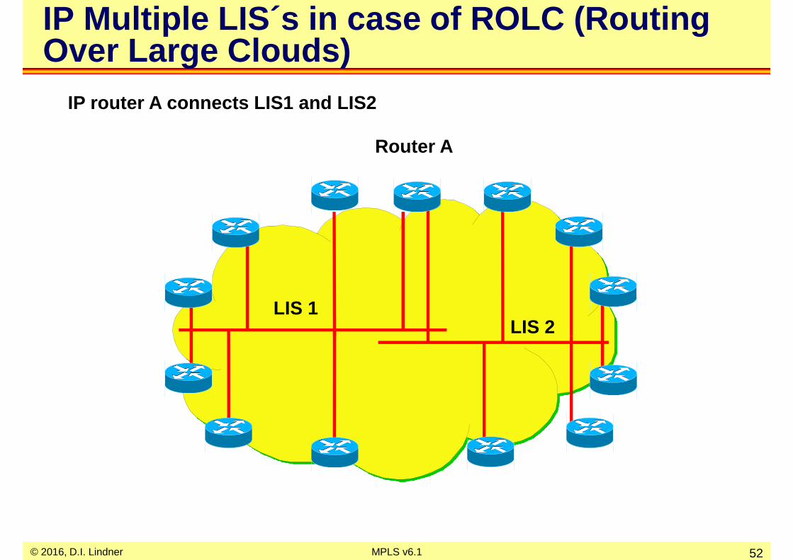
Scalability Aspects
• Number of IP peers determines– number of data virtual circuits– number of control virtual circuits– number of duplicate broadcasts on a single wire
• Method to solve the broadcast domain problem– split the network in several LIS (logical IP subnets)– connect LIS’s by normal IP router (ATM-DCE) which is of
course outside the ATM network
• But then another problem arise– traffic between to two systems which both are attached to
the ATM network but belong to different LIS´s must leave the ATM network and enter it again at the connecting IP router (-> SAR delay)
© 2016, D.I. Lindner MPLS v6.1 52
IP Multiple LIS ´s in case of ROLC (Routing Over Large Clouds)
IP router A connects LIS1 and LIS2
LIS 1LIS 2
Router A

© 2016, D.I. Lindner MPLS v6.1 53
Some Solutions for the ROLC Problem
• NHRP (Next Hop Resolution Protocol)– creates an ATM shortcut between two systems of different
LIS´s
• MPOA (Multi Protocol Over ATM)– LANE + NHRP combined
– creates an ATM shortcut between two systems of different LIS´s
• In both methods– the ATM shortcut is created if traffic between the two
systems exceeds a certain threshold -> data-flow driven– a lot of control virtual circuits (p-t-p and p-t-m) is required

© 2016, D.I. Lindner MPLS v6.1 54
Source
ATM Network
LogicalNetwork
LIS4
LogicalNetwork
LIS3
LogicalNetwork
LIS2
LogicalNetwork
LIS1
Wish for Optimized Connectivity
Classical Path
Optimized Path
Destination

© 2016, D.I. Lindner MPLS v6.1 55
NH-RequestNH-Reply
NHS1
NHS2 NHS3
NHS4
Next Hop Server
ATM Network
LIS1 LIS2 LIS3 LIS4
Direct Connection
Next Hop Resolution Protocol (RFC 2332)
• Next hop requests are passed between next hop serve rs– Next hop servers do not forward data
– Allows direct connection between logical IP subnets across the ATM cloud
– Separates data forwarding path from reachability information
• NHS that knows about the destination sends back a N H-reply

© 2016, D.I. Lindner MPLS v6.1 56
Agenda
• Review ATM• IP over WAN Problems (Traditional Approach)
– Introduction, Base Problem 1• Non-NBMA-View• NMBA-View
– Base Problem 2, Solution
• MPLS Principles• Label Distribution Methods• MPLS Details (Cisco)• RFCs

© 2016, D.I. Lindner MPLS v6.1 57
IP Performance
• Base problem Nr.2– IP forwarding is slow compared to ATM cell forwarding
• IP routing paradigm• hop-by-hop routing with (recursive) IP routing table lookup, IP TTL
decrement and IP checksum computing• destination based routing (large tables in the core of the Internet)
– Load balancing• in a stable network all IP datagram's will follow the same path
(least cost routing versus ATM´s QoS routing)
– QoS (Quality of Service)• IP is connectionless packet switching (best-effort delivery versus
ATM´s guarantees)
– VPN (Virtual Private Networks)• ATM VC´s have a natural closed user group (=VPN) behavior

© 2016, D.I. Lindner MPLS v6.1 58
Basic Ideas to Solve the Problems
• Make ATM topology visible to IP routing– to solve the scalability problems– a classical ATM switch gets IP router functionality
• Divide IP routing from IP forwarding– to solve the performance problems
– IP forwarding based on ATM´s label swapping paradigm (connection-oriented packet switching)
– IP routing based on classical IP routing protocols
• Combine best of both– forwarding based on ATM label swapping paradigm– routing done by traditional IP routing protocols
© 2016, D.I. Lindner MPLS v6.1 59
MPLS
• Several similar technologies were invented in the mid -1990s– IP Switching (Ipsilon)– Cell Switching Router (CSR, Toshiba)
– Tag Switching (Cisco)– Aggregated Route-Based IP Switching (ARIS, IBM)
• IETF merges these technologies– MPLS (Multi Protocol Label Switching)
• note: multiprotocol means that IP is just one possible protocol to be transported by a MPLS switched network
– RFC 3031

© 2016, D.I. Lindner MPLS v6.1 60
Agenda
• Review ATM• IP over WAN Problems (Traditional Approach) • MPLS Principles• Label Distribution Methods• MPLS Details (Cisco)• RFCs

© 2016, D.I. Lindner MPLS v6.1 61
MPLS Approach
• Traditional IP uses the same information for– path determination (routing)– packet forwarding (switching)
• MPLS separates the tasks– L3 addresses used for path determination
– labels used for switching
• MPLS Network consists of– MPLS Edge Routers and MPLS Switches
• MPLS Edge Routers and MPLS Switches– exchange routing information about L3 IP networks– exchange forwarding information about the actual usage
of labels

MPLS Network
MPLS Core Router (Switch)MPLS Edge Router
IP - MPLS Network
… Router Component +
Control Component
… Forwarding Component
© 2016, D.I. Lindner 62MPLS v6.1
Label Distribution Protocol (LDP)
IP Routing Protocol (e.g. OSPF)
© 2016, D.I. Lindner MPLS v6.1 63
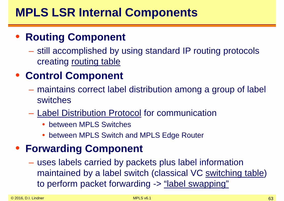
MPLS LSR Internal Components
• Routing Component– still accomplished by using standard IP routing protocols
creating routing table
• Control Component– maintains correct label distribution among a group of label
switches– Label Distribution Protocol for communication
• between MPLS Switches• between MPLS Switch and MPLS Edge Router
• Forwarding Component– uses labels carried by packets plus label information
maintained by a label switch (classical VC switching table) to perform packet forwarding -> “label swapping”

© 2016, D.I. Lindner MPLS v6.1 64
Routing Process
RoutingProtocol
LabelDistribution
Protocol
labeled datapackets in
Routing Table
(RT)
Generic Overview of MPLS LSR Internal Processes and Communication
Label Mgt.Process
Label Information
Base (LIB)
labeled data packets out
Routing Component
Forwarding Component
controlpackets in for routing and
label distribution
LabelDistribution
Protocol
ForwardingProcess
RoutingProtocol
Label Switching Table
Control Component
controlpackets out for
routing and label distribution

MPLS Label Swapping
1a. Routing protocol (e.g. OSPF) establishes reachability to destination networks
1b. Label Distribution Protocol establishes MPLS paths (VC) along switching tables
4. Egress MPLS router at egress removes label and delivers packet
2. Ingress MPLS router receives packet,
“labels” it and by sends it along a particular MPLS path (VC)
3. MPLS switcheslabeled packetsusing switching table
© 2016, D.I. Lindner 65MPLS v6.1

© 2016, D.I. Lindner MPLS v6.1 66
MPLS Header: Frame Mode
• "Layer 2.5“ can be used over Ethernet, 802.3 or PPP links• note: 2.5 means 32 bit
– 20-bit MPLS label (Label)– 3-bit experimental field (Exp)
• could be copy of IP Precedence -> MPLS QoS like IP QoS with DiffServ Model based on DSCP
– 1-bit bottom-of-stack indicator (S)• Labels could be stacked (Push & Pop)
• MPLS switching performed always on the first label of the stack
– 8-bit time-to-live field (TTL)
Layer 2(Ethernet, PPP)
Label Exp S TTL IP
20 Bit 3 1 8
One 4 Byte MPLS header
Layer 2MPLS
Header 1MPLS
Header 2MPLS
Header 3IP
Label Stack

© 2016, D.I. Lindner MPLS v6.1 67
MPLS Header: Cell Mode
MPLSHeader 2 IP Packet
AAL5 Trailer
ATM Convergence Sublayer (CS):
• ATM Switches can only switch VPI/VCI—no MPLS labels!– Only the topmost label is inserted in the VPI/VCI field
GFC VPI VCI PTI CLP HEC IP Header
Topmost Label
(first cell)
DATA
GFC VPI VCI PTI CLP HEC
Topmost Label
(subsequent cells)
DATA
MPLS Header(s)
MPLSHeader 2 IP Packet
ATM Segmentation and Reassembling Sublayer (SAR):
MPLSHeader 1
MPLSHeader 1

© 2016, D.I. Lindner MPLS v6.1 68
Labels and FEC
• A label is used to identify a certain subset of packets – which take the same MPLS path or which get the same
forwarding treatment in the MPLS label switched network
– The path is so called Label Switched Path (LSP)• “The MPLS Virtual Circuit”
• Thus a label represents– a so called Forwarding Equivalence Class (FEC)
• The assignment of a packet to FEC– is done just once by the MPLS Edge Router, as the
packet enters the network
– most commonly this is based on the IP network layer destination address

© 2016, D.I. Lindner MPLS v6.1 69
Label Binding
• Two neighboring LSRs R1 and R2– may agree that when R1 transmits a packet to R2, R1 will
label with packet with label value L if and only if the packet is a member of a particular FEC F
• They agree – on a so called "binding" between label L and FEC F for
packets moving from R1 to R2
• As a result – L becomes R1´s "outgoing label" or “remote label”
representing FEC F– L becomes R2´s "incoming label" or “local label”
representing FEC F

© 2016, D.I. Lindner MPLS v6.1 70
Creating and Destroying Label Binding 1
• Control Driven (favored by IETF -WG)– creation or deconstruction of labels is triggered by control
information such as• OSPF routing, IS-IS routing• PIM Join/Prune messages in case of IP multicast routing• IntSrv RSVP messages in case of IP QoS IntSrv Model• DiffSrv Traffic Engineering in Case of IP QoS DiffSrv Model
– hence we have a pre-assignment of labels based on reachability information
• and optionally based on QoS needs
– also called Topology Driven

© 2016, D.I. Lindner MPLS v6.1 71
Creating and Destroying Label Binding 2
• Data Driven– creation or deconstruction of labels is triggered by data
packets• but only if a critical threshold number of packets for a specific
communication relationship is reached• may have a big performance impact
– hence we have dynamic assignment of labels based on data flow detection
– also called Traffic Driven

© 2016, D.I. Lindner MPLS v6.1 72
Some FEC Examples for Topology Driven
• FECs could be for example– a set of unicast packets whose network layer destination
address matches a particular IP address prefix• MPLS application: Destination Based (Unicast) Routing
– a set of multicast packets with the same source and destination network layer address
• MPLS application: Multicast Routing
– a set of unicast packets whose network layer destination address matches a particular IP address prefix and whose Type of Service (ToS) or DSCP bits are the same
• MPLS application: Quality of Service• MPLS application: Traffic Engineering or Constraint Based Routing

© 2016, D.I. Lindner MPLS v6.1 73
Label Distribution
• MPLS architecture allows an LSR to distribute bindings to LSRs that have not explicitly requested them – “Unsolicited Downstream" label distribution– usually used by Frame-Mode MPLS
• MPLS architecture allows an LSR to explicitly request, from its next hop for a particular FEC, a label binding for that FEC – “Downstream-On-Demand" label distribution
– must be used by Cell-Mode MPLS

© 2016, D.I. Lindner MPLS v6.1 74
Label Binding
• The decision to bind a particular label L to a particular FEC F – is made by the LSR which is DOWNSTREAM with respect
to that binding
– the downstream LSR then informs the upstream LSR of the binding
– thus labels are "downstream-assigned“
– thus label bindings are distributed in the "downstream to upstream“ direction
• Discussion were about if – labels should also be “upstream-assigned“– not any longer part of current MPLS-RFC

© 2016, D.I. Lindner MPLS v6.1 75
Label Retention Mode 1
• A LSR may receive a label binding – for a particular FEC from another LSR, which is not next
hop based on the routing table for that FEC
• This LSR then has the choice– of whether to keep track of such bindings, or whether to
discard such bindings
• A LSR supports "Liberal Label Retention Mode " – if it maintains the bindings between a label and a FEC
which are received from LSR´s which are not its next hop for that FEC

© 2016, D.I. Lindner MPLS v6.1 76
Label Retention Mode 2
• A LSR supports "Conservative Label Retention mode "– If it discards the bindings between a label and a FEC
which are received from LSR´s which are not its next hop for that FEC
• Liberal Label Retention mode– allows for quicker adaptation to routing changes
– LSR can switch over to next best LSP
• Conservative Label Retention mode – requires an LSR to maintain fewer labels– LSR has to wait for new label bindings in case of topology
changes

© 2016, D.I. Lindner MPLS v6.1 77
Independent versus Ordered Control
• Independent Control:– each LSR may make an independent decision to assign a
a label to a FEC and to advertise the assignment to its neighbors
– typically used in Frame-Mode MPLS for destination based routing
– loop prevention must be done by other means (-> MPLS TTL) but there is faster convergence
• Ordered Control:– label assignment proceeds in an orderly fashion from one
end of a LSP to the other– under ordered control, LSP setup may be initiated by the
ingress (header) or egress (tail) MPLS Edge Router

© 2016, D.I. Lindner MPLS v6.1 78
Ordered Control - Egress
– in case of egress method the only LSR which can initiate the process of label assignment is the egress LSR
– a LSR knows that it is the egress for a given FEC if its next hop for this FEC is not an LSR
– this LSR will sent a label advertisement to all neighboring LSRs
– a neighboring LSR receiving such a label advertisement from a interface which is the next hop to a given FEC will assign its own label and advertise it to all other neighboring LSRs
– inherent loop prevention – slower convergence

© 2016, D.I. Lindner MPLS v6.1 79
Ordered Control - Ingress
– in case of ingress method the LSR which initiates the process of label assignment is the ingress LSR
– the ingress LSR constructs a source route and pass on requests for label bindings to the next LSR
– this is done until LSR which is the end of the source route is reached
– from this LSR label bindings will flow upstream to the ingress LSR
– used for MPLS Traffic Engineering (TE)

© 2016, D.I. Lindner MPLS v6.1 80
MPLS Applications and MPLS Control Plane
Any IGP
IP RT
LDP/TDP
Label Switching Table
Different Control Planes
Data Plane (Forwarding Plane)
Unicast Fwd.
M-RT
PIMv2
Multicast Fwd.
OSPF/ISIS
IP RT
LDP
MPLS TE
Any IGP
IP RT
LDP/TDP
MPLS QoS
IP RT
MPLS VPN
RSVP LDP BGP
Any IGP

© 2016, D.I. Lindner MPLS v6.1 81
Agenda
• Review ATM• IP over WAN Problems (Traditional Approach) • MPLS Principles• Label Distribution Methods
– Unsolicited Downstream– Downstream On Demand
– MPLS and ATM, VC Merge Problem
• MPLS Details (Cisco)• RFCs

© 2016, D.I. Lindner MPLS v6.1 82
Routing Table Created by Routing Protocol
171.69
128.89.10
i/f 0
i/f 1
i/f 0
i/f 0
addressprefix interface
128.89.10171.69
01
...addressprefix interface
128.89.10171.69
11
...
addressprefix interface
128.89.10 0...
addressprefix interface
171.69 0...
i/f 1
FEC Label Binding:Control Driven
Destination Based Routing
Data Flow
Routing Table
LSR
LER
LER
LER

© 2016, D.I. Lindner MPLS v6.1 83
Labels Sent by LDP
addressprefix171.69
...
locallabel ifremote
label0x7
addressprefix
128.89.10...
locallabel ifremote
label0x5address
prefix128.89.10
171.69...
locallabel ifremote
label01
57
171.69
128.89.10
i/f 0
i/f 1
i/f 0
i/f 0
Advertises binding<5,128.89.10>
Advertises binding<7,171.69>
i/f 1
Label Distribution:Unsolicited Downstream
addressprefix
128.89.10171.69
...
addresslabel
128.89.10171.69
...
locallabel ifremote
label11
xx
Data Flow
Label Binding
Routing
Table (RT)
Switching
Table (ST)
Advertisings received from the IP next hop
(RT) for those networks (FECs) -> switching table

© 2016, D.I. Lindner MPLS v6.1 84
Labels Sent and Switching Table Entry Created by MPLS Switch
addressprefix171.69
...
locallabel ifremote
label0x7
addressprefix
128.89.10...
locallabel ifremote
label0x5
171.69
128.89.10
i/f 0
i/f 1
i/f 1
i/f 0
i/f 0
addressprefix
128.89.10171.69
...
addresslabel
128.89.10171.69
...
locallabel ifremote
label11
34
xx
addressprefix
128.89.10171.69
...
locallabel ifremote
label01
57
34
Advertises bindings<3,128.89.10>
<4,171.69>
Label Distribution:Unsolicited Downstream
Data Flow
Label
Binding
Advertisings received from the IP next hop
(RT) for those networks (FECs) -> switching table

© 2016, D.I. Lindner MPLS v6.1 85
MPLS Switched Packets
addressprefix
128.89.10171.69
...
addressprefix
128.89.10171.69
...
locallabel ifremote
label11
34
xx
addressprefix171.69
...
locallabel
remotelabel
x7
addressprefix
128.89.10171.69
...
locallabel ifremote
label01
57
0
1
1
34
171.69.12.1 data 171.69.12.1 data4
171.69.12.1 data171.69.12.1 data7MPLS Edge Router
does longest match,adds (“impose”) label
subsequentMPLS switch
forwards on label(based on ST),
swaps label
last MPLS routerstrip off the label
(“untag”) and routes packet based on RTData Flow
MPLS Path = LSP to FEC 128.89.10
MPLS Path = LSP to FEC 171.69
128.89.10
171.69
Label
Swapping

© 2016, D.I. Lindner MPLS v6.1 86
Routing Table Created by Routing Protocol
135.24.50
i/f 0
i/f 0
i/f 0
addressprefix interface
135.24.50 0
...addressprefix interface
135.24.50 1
...
addressprefix interface
135.24.50 0...
addressprefix interface
135.24.50 0...
i/f 1
FEC Label Binding:Control Driven
Destination Based Routing
Data Flow
LSR
LER
LER
LER

© 2016, D.I. Lindner MPLS v6.1 87
Labels Sent by LDP
addressprefix
135.24.50...
locallabel ifremote
label0x
addressprefix
135.24.50...
locallabel ifremote
label0xaddress
prefix135.24.50
...
locallabel ifremote
label05
Advertises binding<5, 135.24.50>
Label Distribution:Unsolicited Downstream
addressprefix
128.89.10171.69
addresslabel
135.24.50
locallabel ifremote
label1x5
Data Flow
135.24.50
i/f 0
i/f 0
i/f 0
i/f 1
Advertising received from the IP next hop
(RT) for those networks (FECs) -> switching table

© 2016, D.I. Lindner MPLS v6.1 88
Labels Sent and Switching Table Entry Created by MPLS Switch
addressprefix
135.24.50...
locallabel ifremote
label07x
addressprefix
135.24.50...
locallabel ifremote
label07xaddress
prefix135.24.50
...
locallabel if
7
remotelabel
05
Label Distribution:Unsolicited Downstream
addressprefix
128.89.10171.69
addresslabel
135.24.50
locallabel ifremote
label1x5
Data Flow
135.24.50
i/f 0
i/f 0
i/f 0
i/f 1
Advertises binding<7, 135.24.50>
Advertises binding<7, 135.24.50>
Advertisings received from the IP next hop
(RT) for those networks (FECs) -> switching table

© 2016, D.I. Lindner MPLS v6.1 89
Label Merging - LSP Merging
0
0
1
135.24.50.1 data 135.24.50.1 data5
135.24.50.1 data135.24.50.1 data7
MPLS Edge Router does longest match,adds (“imose”) label
subsequentMPLS switch
forwards on label,swaps label
last MPLS routerstrip off the labeland routes packet
MPLS Path = LPS to FEC 135.24.50
addressprefix
128.89.10171.69
addresslabel
135.24.50
locallabel ifremote
label1x5
addressprefix
135.24.50
...
locallabel if
7
remotelabel
05addressprefix
135.24.50...
locallabel ifremote
label07x
0
Data Flow
MPLS Path = LSP to FEC 135.24.50
MPLS Path = LSP to FEC 135.24.50
135.24.50

© 2016, D.I. Lindner MPLS v6.1 90
Agenda
• Review ATM• IP over WAN Problems (Traditional Approach) • MPLS Principles• Label Distribution Methods
– Unsolicited Downstream– Downstream On Demand
– MPLS and ATM, VC Merge Problem
• MPLS Details (Cisco)• RFCs

© 2016, D.I. Lindner MPLS v6.1 91
Routing Table Created by Routing Protocol
171.69
128.89.10
i/f 0
i/f 1
i/f 0
i/f 0
addressprefix interface
128.89.10171.69
01
...addressprefix interface
128.89.10171.69
11
...
addressprefix interface
128.89.10 0...
addressprefix interface
171.69 0...
i/f 1
FEC Label Binding:Control Driven
Destination Based Routing
LSR
LER
LER
LER

© 2016, D.I. Lindner MPLS v6.1 92
Labels Requested by MPLS Edge Routers
addressprefix171.69
...
locallabel ifremote
label0x
addressprefix
128.89.10...
locallabel ifremote
label0xaddress
prefix128.89.10
171.69...
locallabel ifremote
label01
171.69
128.89.10
i/f 0
i/f 1
i/f 0
i/f 0
i/f 1
Label Distribution:Downstream-On-Demand
Request binding<171.69>
addressprefix
128.89.10171.69
...
addresslabel
128.89.10171.69
...
locallabel ifremote
label11
xx
Request binding<128.89.10>
Data FlowRequest binding are sent in direction
of the IP next hop (RT) for these
networks (FECs)

© 2016, D.I. Lindner MPLS v6.1 93
Labels Requested by MPLS Switch
addressprefix171.69
...
locallabel ifremote
label0x
addressprefix
128.89.10...
locallabel ifremote
label0xaddress
prefix128.89.10
171.69...
locallabel ifremote
label01
171.69
128.89.10
i/f 0
i/f 1
i/f 0
i/f 0
i/f 1
Label Distribution:Downstream-On-Demand
addressprefix
128.89.10171.69
...
addresslabel
128.89.10171.69
...
locallabel ifremote
label11
xx
Request binding<171.69>
Request binding<128.89.10>
Data Flow
Request binding are passed on in direction
of the IP next hop (RT) for these networks (FECs)

© 2016, D.I. Lindner MPLS v6.1 94
Labels Allocated by MPLS Edge Router
addressprefix171.69
...
locallabel ifremote
label0x7
addressprefix
128.89.10...
locallabel ifremote
label0x5address
prefix128.89.10
171.69...
locallabel ifremote
label01
57
171.69
128.89.10
i/f 0
i/f 1
i/f 0
i/f 0
i/f 1
Label Distribution:Downstream-On-Demand
addressprefix
128.89.10171.69
...
addresslabel
128.89.10171.69
...
locallabel ifremote
label11
xx Advertises binding
<5,128.89.10>
Advertises binding<7,171.69>
Data Flow
Advertise-Bindings caused by former requests
will lead to entries in the switching table
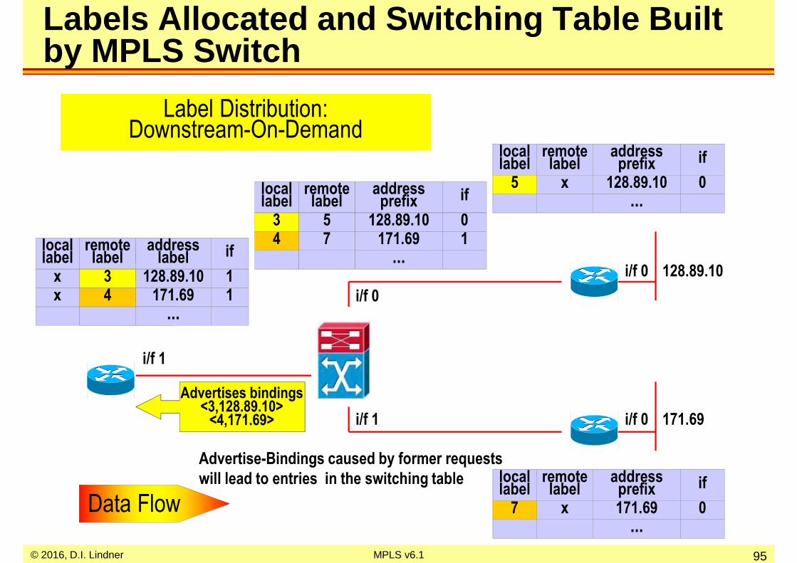
© 2016, D.I. Lindner MPLS v6.1 95
Labels Allocated and Switching Table Built by MPLS Switch
addressprefix171.69
...
locallabel ifremote
label0x7
addressprefix
128.89.10...
locallabel ifremote
label0x5
171.69
128.89.10
i/f 0
i/f 1
i/f 1
i/f 0
i/f 0
addressprefix
128.89.10171.69
...
addresslabel
128.89.10171.69
...
locallabel ifremote
label11
34
xx
addressprefix
128.89.10171.69
...
locallabel ifremote
label01
57
34
Advertises bindings<3,128.89.10>
<4,171.69>
Label Distribution:Downstream-On-Demand
Data Flow
Advertise-Bindings caused by former requests
will lead to entries in the switching table

© 2016, D.I. Lindner MPLS v6.1 96
MPLS Switched Packets
addressprefix
128.89.10171.69
...
addressprefix
128.89.10171.69
...
locallabel ifremote
label11
34
xx
addressprefix171.69
...
locallabel
remotelabel
x7
addressprefix
128.89.10171.69
...
locallabel ifremote
label01
57
0
1
1
34
171.69.12.1 data 171.69.12.1 data4
171.69.12.1 data
171.69.12.1 data7MPLS Edge Router does longest match,
adds label
subsequentMPLS switch
forwards solelyon label,
swaps label
last MPLS routerstrip off the labeland routes packet
Data Flow
MPLS Path = LSP to FEC 128.89.10
MPLS Path = LSP to FEC 171.69
128.89.10
171.69

© 2016, D.I. Lindner MPLS v6.1 97
Routing Table Created by Routing Protocol
135.24.50
i/f 0
i/f 0
i/f 0
addressprefix interface
135.24.50 0
...addressprefix interface
135.24.50 1
...
addressprefix interface
135.24.50 0...
addressprefix interface
135.24.50 0...
i/f 1
FEC Label Binding:Control Driven
Destination Based Routing
Data Flow
LSR
LER
LER
LER

© 2016, D.I. Lindner MPLS v6.1 98
Labels Requested by MPLS Edge Routers
addressprefix
135.24.50...
locallabel ifremote
label0x
addressprefix
135.24.50...
locallabel ifremote
label0x
addressprefix
135.24.50
...
locallabel out-ifremote
label0
requests binding< 135.24.50 >
addressprefix
128.89.10171.69
addresslabel
135.24.50
locallabel ifremote
label1x
Data Flow
135.24.50
i/f 0
i/f 0
i/f 0
i/f 1
Label Distribution:Downstream-On-Demand
in-if
1
i/f 1
i/f 2
2
request binding< 135.24.50 >

© 2016, D.I. Lindner MPLS v6.1 99
Labels Requested by MPLS Switch
Data Flow
135.24.50
i/f 0
i/f 0
i/f 0
i/f 1
Label Distribution:Downstream-On-Demand
requests binding< 135.24.50 >
request binding< 135.24.50 >
addressprefix
135.24.50...
locallabel ifremote
label0x
addressprefix
135.24.50...
locallabel ifremote
label0x
addressprefix
135.24.50
...
locallabel out-ifremote
label0
addressprefix
128.89.10171.69
addresslabel
135.24.50
locallabel ifremote
label1x
in-if
12
i/f 1
i/f 2

© 2016, D.I. Lindner MPLS v6.1 100
Labels Allocated by MPLS Edge Router
Data Flow
135.24.50
i/f 0
i/f 0
i/f 0
i/f 1
Label Distribution:Downstream-On-Demand
addressprefix
135.24.50...
locallabel ifremote
label0x
addressprefix
135.24.50...
locallabel ifremote
label0x
addressprefix
135.24.50135.24.50
...
locallabel out-ifremote
label00
57
addressprefix
128.89.10171.69
addresslabel
135.24.50135.24.50
locallabel ifremote
label11
xx
57
in-if
12
i/f 1
i/f 2advertise binding< 5, 135.24.50 >
advertise binding<7, 135.24.50 >

© 2016, D.I. Lindner MPLS v6.1 101
Labels Allocated and Switching Table Built by MPLS Switch
Data Flow
135.24.50
i/f 0
i/f 0
i/f 0
i/f 1
Label Distribution:Downstream-On-Demand
addressprefix
135.24.50...
locallabel ifremote
label0x4
addressprefix
135.24.50...
locallabel ifremote
label0x3
addressprefix
135.24.50135.24.50
...
locallabel out-if
34
remotelabel
00
57
addressprefix
128.89.10171.69
addresslabel
135.24.50135.24.50
locallabel ifremote
label11
xx
57
in-if
12
i/f 1
i/f 2
advertise binding<3, 135.24.50 >
advertise binding<4, 135.24.50 >

© 2016, D.I. Lindner MPLS v6.1 102
Two Separate LSPs
0
0
1
135.24.50.1 data 135.24.50.1 data7
135.24.50.1 data135.24.50.1 data4
MPLS Edge Router does longest match,
adds label
subsequentMPLS switch
forwards solelyon label,
swaps label
last MPLS routerstrip off the labeland routes packet
MPLS Path = LPS to FEC 135.24.50addressprefix
135.24.50...
locallabel ifremote
label0x40
Data Flow
MPLS Path 2 = LSP 2 to FEC 135.24.50
MPLS Path 1 = LSP 1 to FEC 135.24.50
addressprefix
135.24.50135.24.50
...
locallabel out-if
34
remotelabel
00
57
in-if
12
1
2
addressprefix
128.89.10171.69
addresslabel
135.24.50135.24.50
locallabel ifremote
label11
xx
57
135.24.50
addressprefix
135.24.50...
locallabel ifremote
label0x3
© 2016, D.I. Lindner MPLS v6.1 103
Agenda
• Review ATM• IP over WAN Problems (Traditional Approach) • MPLS Principles• Label Distribution Methods
– Unsolicited Downstream– Downstream On Demand
– MPLS and ATM, VC Merge Problem
• MPLS Details (Cisco)• RFCs

© 2016, D.I. Lindner MPLS v6.1 104
Label Switching and ATM
• Can be easily deployed with ATM because ATM uses label swapping– VPI/VCI is used as a label
• ATM switches needs to implement control component of label switching– ATM attached router peers with ATM switch (label switch)
• exchange label binding information
• Differences– how labels are set up
• label distribution -> downstream on demand allocation
– label merging• in order to scale, merging of multiple streams (labels) into one
stream (label) is required

© 2016, D.I. Lindner MPLS v6.1 105
Label Switching and ATM
addressprefix128.89
...
locallabel ifremote
label01
3y
5
5 5 55
5 5 55
3 3 33 3 3
ATM switch interleaves cells of different packets o nto same label.That is a problem in case of AAL5 encapsulation.No problem in case of AAL3/AAL4 encapsulation becau se of AAL3/AAL4´s inherent multiplexing capability.
128.89
IP Packet
IP Packet

© 2016, D.I. Lindner MPLS v6.1 106
Label Distribution Solution for ATM
addressprefix128.89128.89
...
inputi/f
locallabel
55
12
128.89
remotelabel
37
outputi/f00
requests a labelfor 128.89
requests a labelfor 128.89
requests two labels for 128.89
returns a label to each requester
• “Downstream On Demand” Label Distribution

© 2016, D.I. Lindner MPLS v6.1 107
Label Distribution Solution for ATM
• Downstream On Demand label distribution is necessar y– multiple labels per FEC may be assigned– one label per (ingress, egress) router pair
• Label space can be reduced with VC -merge technique
5 5 55
5 5 55
3 7 37 7 3
128.89
addressprefix128.89128.89
...
inputi/f
locallabel
55
12
remotelabel
37
outputi/f00

© 2016, D.I. Lindner MPLS v6.1 108
VC Merge Technique
addressprefix128.89
...
locallabel ifremote
label035
5 5 55
5 5 55
3 3 33 3 3
128.89
• ATM switch avoids interleaving of frames – VC Merge technique – looking for AAL5 trailers and storing corresponding cells of a
frame until AAL5 trailer is seen

© 2016, D.I. Lindner MPLS v6.1 109
Agenda
• Review ATM• IP over WAN Problems (Traditional Approach) • MPLS Principles• Label Distribution Methods• MPLS Details (Cisco)
– Internal Components
– MPLS in Action– TDP, LDP– TTL– Traffic Engineering
– MPLS and BGP
• RFCs

© 2016, D.I. Lindner MPLS v6.1 110
Routing Process
RoutingProtocol
LabelDistribution
Protocol
labeled datapackets in
Routing Table
(RT)
Generic MPLS Control and Data Plane
Label Mgt.Process
Label Information
Base (LIB)
labeled data packets out
Control Plane
Data Plane control
packets incontrol
packets out
LabelDistribution
Protocol
ForwardingProcess
RoutingProtocol
Label Switching Table
MPLS Domain MPLS Domain

© 2016, D.I. Lindner MPLS v6.1 111
Routing Process
Label Forwarding Information Base
(LFIB) = Label Switching Table
RoutingProtocol
LabelDistribution
Protocol
Incoming labeled packets
Routing Table
(RT)
Frame Mode MPLS for IP at LSR (Cisco)
e.g.IP OSPF
Label Mgt.Process
Label Information
Base (LIB)
e.g.MPLS LDP
(RFC)
or Cisco´s TDP
Forwarding Information Base (FIB)
= Optimized RT Cache, Cisco´s CEF
Outgoing labeled packets
Incoming IP datagram´s
Control Plane
Data Plane Outgoing IP datagram´s
MPLS Domain MPLS Domain

© 2016, D.I. Lindner MPLS v6.1 112
Routing Process
Label Forwarding Information Base
(LFIB) = Label Switching Table
RoutingProtocol
Routing Table
(RT)
Frame Mode MPLS for IP at Edge (LER) 1
Label Mgt.Process
Label Information
Base (LIB)
Forwarding Information Base (FIB)
= Optimized RT Cache, Cisco´s CEF
Outgoing labeled packets
Incoming IP datagram´s
Control Plane
Data Plane Outgoing IP datagram´s
RoutingProtocol
LabelDistribution
Protocol
MPLS Domain
L3 lookup may point to LFIB andlabel inserted

© 2016, D.I. Lindner MPLS v6.1 113
Routing Process
Label Forwarding Information Base
(LFIB) = Label Switching Table
RoutingProtocol
Routing Table
(RT)
Frame Mode MPLS for IP at Edge (LER) 2
Label Mgt.Process
Label Information
Base (LIB)
Forwarding Information Base (FIB)
= Optimized RT Cache, Cisco´s CEF
Incoming labeled packets
Outgoing IP datagram´s
Control Plane
Data Plane Incoming IP datagram´s
RoutingProtocol
LabelDistribution
Protocol
MPLS Domain
after label removal subsequentL3 lookup

© 2016, D.I. Lindner MPLS v6.1 114
Important Databases
• FIB– Forwarding Information Base– This is the CEF database at Cisco routers– Contains L2/L3 headers, IP addresses, labels, next hop,
metric• The routing table is only a subset of the FIB
• LIB – Label Information Base
– Contains all labels and associated destinations
• LFIB– Label Forwarding Information Base– Contains selected labels used for forwarding
• Selection based on FIB

© 2016, D.I. Lindner MPLS v6.1 115
Cisco Express Forwarding (CEF)
• Requirement for MPLS– Forwarding information (L2-headers, addresses, labels)
are maintained in FIB for each destination– Newest and fastest IOS switching method
– Critical in environments with frequent route changes and large RT’s: The Internet backbone!
• Invented to overcome Fast Switching problems:– Originally Hash table, since 10.2 2-way radix-tree
– No overlapping cache entries– Any change of RT or ARP cache invalidates route cache– First packet is always process-switched to build route
cache entry– Inefficient load balancing when "many hosts to one server"

© 2016, D.I. Lindner MPLS v6.1 116
How CEF Works
– CEF "Fast Cache" consists of– CEF table: Stripped-down version of the RT (256-way mtrie data structure)– Adjacency table: Actual forwarding information (MAC, interfaces, ...)
– CEF cache is pre-built before any packets are switched– No packet needs to be process switched
– CEF entries never age out– Any RT or ARP changes are immediately mapped into CEF cache
root
1.0.0.0
2.0.0.0
10.0.0.0
...
...
255.0.0.0
10.1.0.0
10.2.0.0
10.20.0.0
...
...
10.255.0.0
10.20.1.0
10.20.2.0
10.20.5.0
...
...
10.20.255.0
10.20.5.1
10.20.5.2
...
...
10.20.5.255
00E3.C10F.8B11
Interface e0/0
...
Adjacency Table
Example-Look up "10.20.5.16“
CEF Table
CEF Table is built directly from the RTAdjacency Table is built directly from the ARP cach e in case of LAN
Attention: For an IP-Prefix the pointer to the Adjacency Table will start earlier in the structure
10.20.5.16
...
Adj Tab
Example-Look up "10.20.255.x“

Classical IP Forwarding: Hop by Hop Forwarding
RT
10/8 via R6
R1 R2 R3 R4 R5 R6
10/8 exist RoutingUpdate
10/8
RT
10/8 via R5
RT
10/8 via R4
RT
10/8 via R3
RT
10/8 via R2
10/8 exist 10/8 exist 10/8 exist 10/8 exist
10.0.0.1 10.0.0.1 10.0.0.1 10.0.0.1 10.0.0.1
© 2016, D.I. Lindner 117MPLS v6.1

MPLS Switching In Action: Label Distribution
– Both routing updates and LDP/TDP distribute reachability information
– “in” = local label created by the router itself and advertized– “out” = remote label received from other routers
RT
10/8 via R6
FIB
10/8 via R6 no lab.
R1CE
R2Edge router (PE)
R3Core router (P)
R4Core router (P)
R5Edge router (PE)
R6CE
10/8 exist RoutingUpdate
10/8FIB
10/8 via R5 use 41
FIB
10/8 via R4 use 22
FIB
10/8 via R3 use 89
LFIB
In
-
Out
89
10/8 use 4110/8 use 2210/8 use 89
LDP Binding
RT
10/8 via R5
RT
10/8 via R4
RT
10/8 via R3
RT
10/8 via R2
10/8 exist 10/8 exist 10/8 exist 10/8 exist
LFIB
In
89
Out
22
LFIB
In
22
Out
41
LFIB
In
41
Out
Untag
© 2016, D.I. Lindner 118MPLS v6.1
LDP BindingLDP Binding

MPLS Switching In Action: Label Swapping
RT
10/8 via R6
FIB
10/8 via R6 no lab.
10/8FIB
10/8 via R5 use 41
FIB
10/8 via R4 use 22
FIB
10/8 via R3 use 89
10.0.0.1 10.0.0.1 89 10.0.0.1 22 10.0.0.1 41 10.0.0.1
LFIB
Local
-
Remote
89
LFIB
Local
89
Remote
22
LFIB
Local
22
Remote
41
LFIB
Local
41
Remote
Untag
© 2016, D.I. Lindner 119MPLS v6.1
R1CE
R2Edge router (PE)
R3Core router (P)
R4Core router (P)
R5Edge router (PE)
R6CE

MPLS Switching In Action: Penultimate Hop Popping
© 2016, D.I. Lindner MPLS v6.1 120
• Last hop router (R5) tells penultimate router (R4) to remove label– "Penultimate Hop Popping " (PHP)– Also called "Implicit Null Label"
RT
10/8 via R6
FIB
10/8 via R6 no lab.
10/8FIB
10/8 via R5 do POP
FIB
10/8 via R4 use 22
FIB
10/8 via R3 use 89
10/8 do POP10/8 use 2210/8 use 89
LFIB
In
-
Out
89
LFIB
In
89
Out
22
LFIB
In
22
Out
POP
LFIB
Inimplicit
null
Out
-
10/8 exist RoutingUpdate
R1CE
R2Edge router (PE)
R3Core router (P)
R4Core router (P)
R5Edge router (PE)
R6CE

MPLS Switching In Action: Penultimate Hop Popping
© 2016, D.I. Lindner MPLS v6.1 121
• R5 only performs single lookup in FIB
RT
10/8 via R6
FIB
10/8 via R6 no lab.
10/8FIB
10/8 via R4 use 22
FIB
10/8 via R3 use 89
10.0.0.1 10.0.0.1 89 10.0.0.1 22 10.0.0.1 10.0.0.1
FIB
10/8 via R5 do POP
LFIB
In
-
Out
89
LFIB
In
89
Out
22
LFIB
In
22
Out
POP
LFIB
In Outimplicit
null-
R1CE
R2Edge router (PE)
R3Core router (P)
R4Core router (P)
R5Edge router (PE)
R6CE

© 2016, D.I. Lindner MPLS v6.1 122
Cisco IOS Standard Behavior 1
– Routers with packet interfaces (Frame-Mode MPLS)• Per-platform Label Space !!!
– a label assigned by an LSR to a given FEC is used on all interfaces in advertisements of this LSR
• Unsolicited Downstream Label Distribution– label distribution is done unsolicited
• Liberal Label Retention Mode– received labels which are not used by a given LSR are still stored in
the LIB– allows faster convergence of LSP after rerouting
• Independent Control– labels are assigned by LSR independently from each other

© 2016, D.I. Lindner MPLS v6.1 123
Cisco IOS Standard Behavior 2
– Routers with ATM interfaces (Cell-Mode MPLS)• Per-interface Label Space
– a different label for the same FEC is used on each single interface in advertisements of this LSR
• Downstream On Demand Label Distribution– label distribution is done on request
• Conservative or Liberal Label Retention Mode– received labels which are not used by a given LSR are not stored in
the LIB in case of conservative mode
• Independent Control

© 2016, D.I. Lindner MPLS v6.1 124
Cisco IOS Standard Behavior 3
– ATM switches (Cell-Mode MPLS)• Per-interface Label Space• Downstream On Demand Label Distribution• Conservative Label Retention Mode• Ordered control
– labels are assigned by LSR in a controlled fashion from egress to ingress
© 2016, D.I. Lindner MPLS v6.1 125
Agenda
• Review ATM• IP over WAN Problems (Traditional Approach) • MPLS Principles• Label Distribution Methods• MPLS Details (Cisco)
– Internal Components
– MPLS in Action– TDP, LDP– TTL– Traffic Engineering
– MPLS and BGP
• RFCs

© 2016, D.I. Lindner MPLS v6.1 126
Building Routing Tables
• Routing Protocol – establish routing tables RT in all routers– best path based on metric is stored in RT
• RT– contains next hop information (outgoing
interface)• FIB
– additionally contains outgoing label information (which label can be used towards next hop)
RT
10/8 via R5
R1 LER R2 R5 LER
10/8
R3
R4
RT
10/8 via R3
RT
10/8 via R3
RT
10/8 via R2
- - -
LFIB R2
Label Action Next Hop
10/8 R3 none
FIB R2
Net Next Hop Label
- - -
LIB R2
Net Label Type
- --
- --
LSR´s
Assumption: no PHP used

© 2016, D.I. Lindner MPLS v6.1 127
Allocating Labels
• R2– allocates label 49 to FEC 10/8– stored in LIB with type local– stores action untag in LFIB because no other
router has advertised a label for that FEC• Every MPLS router
– allocates labels for all IP destinations found in the routing table
– this is done independently from each other – a label has only local significance
RT
10/8 via R5
R1 R2 R5
10/8
R3
R4
RT
10/8 via R3
RT
10/8 via R3
RT
10/8 via R2
49 untag -
LFIB R2
Label Action Next Hop
10/8 R3 none
FIB R2
Net Next Hop Label
10/8 49 local
LIB R2
Net Label Type
- --
- --

© 2016, D.I. Lindner MPLS v6.1 128
Advertising and Receiving Labels via LDP
• R2– advertises label 49 for FEC 10/8 to all
neighbor routers• Per platform label allocation
– same label on all interfaces– LFIB may not contain an incoming interface
(next HOP) field at that moment• Every neighbor MPLS router
– stores received label for IP destination 10/8 in the corresponding LIB
RT
10/8 via R5
R1 R2 R5
10/8
R3
R4
RT
10/8 via R3
RT
10/8 via R3
RT
10/8 via R2
10/8 49 remote
LIB R3
Net Label Type
- --
10/8 use 49 10/8 use 49
10/8 49 remote
LIB R4
Net Label Type
- --
10/8 49 remote
LIB R1
Net Label Type
- --

© 2016, D.I. Lindner MPLS v6.1 129
Actions on Receiving Labels on R1
• R1– receives label 49 for FEC 10/8 – label is advertised by router which is the next
hop in the routing table -> therefore populates the FIB
– LFIB is adapted to use label 49 for FEC 10/8 towards R2
– action in LFIB has the meaning of outgoinglabel or remote label
– label in LFIB has the meaning of incominglabel or local label
RT
10/8 via R5
R1 R2 R5
10/8
R3
R4
RT
10/8 via R3
RT
10/8 via R3
RT
10/8 via R2
10/8 use 49 10/8 use 49
10/8 49 remote
LIB R1
Net Label Type
- --
10/8 R2 49
FIB R1
Net Next Hop Label
- 49 R2
LFIB R1
Label Action Next Hop

© 2016, D.I. Lindner MPLS v6.1 130
Actions on Receiving of Labels from R3 and R4 on Router R2
RT
10/8 via R5
R1 R2 R5
10/8
R3
R4
RT
10/8 via R3
RT
10/8 via R3
RT
10/8 via R2
10/8 use 22
49 22 R3
LFIB R2
Label Action Next Hop
10/8 R3 22
FIB R2
Net Next Hop Label
10/8 49 local
LIB R2
Net Label Type
22 remote10/8
55 remote10/8
• R2receives label 22 for FEC 10/8 – this label is advertised by router which is the
next hop in the routing table -> therefore populates the FIB
– LFIB is adapted to use (swap) label 22 for FEC 10/8 towards R3
receives label 55 for FEC 10/8– this label is advertised by router which is not
the next hop in the routing table but will be still stored in the LIB -> liberal retention mode
10/8 use 22

© 2016, D.I. Lindner MPLS v6.1 131
Receiving of Labels from R2 and R3 on Router R4
RT
10/8 via R5
R1 R2 R5
10/8
R3
R4
RT
10/8 via R3
RT
10/8 via R3
RT
10/8 via R2
10/8 use 22
55 22 R3
LFIB R4
Label Action Next Hop
10/8 R3 22
FIB R4
Net Next Hop Label
10/8 55 local
LIB R4
Net Label Type
22 remote10/8
49 remote10/8
• R4receives label 22 for FEC 10/8 – this label is advertised by router which is the
next hop in the routing table-> therefore populates the FIB
– LFIB is adapted to use label 22 for FEC 10/8 towards R3
already received label 49 for FEC 10/8– this label is advertised by router which is not
the next hop in the routing table but will be still stored in the LIB
10/8 use 33
Assumption: no PHP used

© 2016, D.I. Lindner MPLS v6.1 132
Label Switching
RT
10/8 via R5
R1 R2 R5
10/8
R3
R4
RT
10/8 via R3
RT
10/8 via R3
RT
10/8 via R2
49 22 R3
LFIB R2
Label Action Next Hop
10/8 R3 22
FIB R2
Net Next Hop Label
10/8 49 local
LIB R2
Net Label Type
22 remote10/8
55 remote10/8
• Packets of FEC 10/8 will follow the corresponding Label Switched Path
10.0.0.1 49 10.0.0.1 22 10.0.0.1 33
Assumption: no PHP used

© 2016, D.I. Lindner MPLS v6.1 133
Link Failure R2 < -> R3
RT
10/8 via R5
R1 R2 R5
10/8
R3
R4
RT
10/8 via ?
RT
10/8 via R3
RT
10/8 via R2
49 22 R3
LFIB R2
Label Action Next Hop
10/8 R3 22
FIB R2
Net Next Hop Label
10/8 49 local
LIB R2
Net Label Type
22 remote10/8
55 remote10/8
• Routing protocol neighbors and LDP neighbors are lost after failure – corresponding entries in FIB, LIB and LFIB are
removed • Traffic
– to FEC 10/8 will not be forwarded until routing table converges
10.0.0.1 49

© 2016, D.I. Lindner MPLS v6.1 134
Routing Protocol Convergence
RT
10/8 via R5
R1 R2 R5
10/8
R3
R4
RT
10/8 via R4
RT
10/8 via R3
RT
10/8 via R2
49 55 R4
LFIB R2
Label Action Next Hop
10/8 R4 55
FIB R2
Net Next Hop Label
10/8 49 local
LIB R2
Net Label Type
10/8
55 remote10/8
• After routing protocol convergence – R2 can switch over immediately to other LSP
if alternative label advertisements were stored in LIB and labeled packets will flow again
– Otherwise R2 must wait for new bindings and can forward packets only based on IP address in the meantime (action untag in LFIB)
• Packets of FEC 10/8 will follow the new Label Switched Path via R4
10.0.0.1 4910.0.0.1 55
10.0.0.1 22
10.0.0.1 33
© 2016, D.I. Lindner MPLS v6.1 135
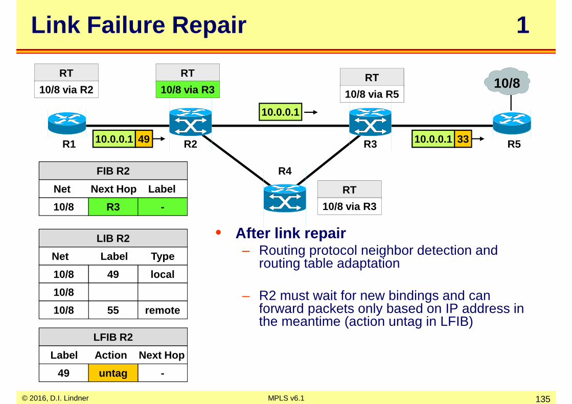
Link Failure Repair 1
RT
10/8 via R5
R1 R2 R5
10/8
R3
R4
RT
10/8 via R3
RT
10/8 via R3
RT
10/8 via R2
49 untag -
LFIB R2
Label Action Next Hop
10/8 R3 -
FIB R2
Net Next Hop Label
10/8 49 local
LIB R2
Net Label Type
10/8
55 remote10/8
• After link repair– Routing protocol neighbor detection and
routing table adaptation
– R2 must wait for new bindings and can forward packets only based on IP address in the meantime (action untag in LFIB)
10.0.0.1 49
10.0.0.1
10.0.0.1 33

© 2016, D.I. Lindner MPLS v6.1 136
Link Failure Repair 2
RT
10/8 via R5
R1 R2 R5
10/8
R3
R4
RT
10/8 via R3
RT
10/8 via R3
RT
10/8 via R2
49 22 R3
LFIB R2
Label Action Next Hop
10/8 R3 22
FIB R2
Net Next Hop Label
10/8 49 local
LIB R2
Net Label Type
22 remote10/8
55 remote10/8
• After LDP session to R3 is up and binding for FEC 10/8 from R3 received– Packets of FEC 10/8 will follow the
corresponding Label Switched Path again
10.0.0.1 49 10.0.0.1 22 10.0.0.1 33
© 2016, D.I. Lindner MPLS v6.1 137
Agenda
• Review ATM• IP over WAN Problems (Traditional Approach) • MPLS Principles• Label Distribution Methods• MPLS Details (Cisco)
– Internal Components
– MPLS in Action– TDP, LDP– TTL– Traffic Engineering
– MPLS and BGP
• RFCs

© 2016, D.I. Lindner MPLS v6.1 138
TDP Key Facts
• Tag Distribution Protocol (TDP)– invented by Cisco– for distributing <label, prefix> bindings– enabled by default
• Session establishment: UDP/TCP port 711– Hello messages via UDP– destination address -> 224.0.0.2
• well-known multicast address for all subnet routers
– TDP session via TCP, incremental updates
• Not compatible with LDP– but can co-exist as long as two peers use the same
protocol

© 2016, D.I. Lindner MPLS v6.1 139
LDP Key Facts
• Label Distribution Protocol• IETF standard RFC 3036
– descendent of Cisco's proprietary TDP
• Same concept but port 646• LDP-Identifier
– Router ID (4 bytes)
– Label Space ID (2 bytes)• in case of per-platform label space this field is set to zero• note: in ATM you need a per-interface label space
• TCP session initiated from router with highest address

© 2016, D.I. Lindner MPLS v6.1 140
LDP Message Types
• Four basic types:– Discovery (UDP):
• getting into contact with neighbor LSR´s
– Adjacency (TCP):• Initialization, Keepalive and Shutdown of LDP sessions
– Label Advertisement (TCP):• Label Binding - Advertisement, - Request, - Withdrawal, - Release
– Notification (TCP):• Signal of Error Information, Advisory Information
• TLV (Type/Length/Value)– encoding is used for easy extension of the protocol

© 2016, D.I. Lindner MPLS v6.1 141
Discovery Message
• Basic discovery of directly connected LSRs:– Hello Message with targeted bit set to 0
• UDP to port 646• IP multicast address “all routers on this subnet” (224.0.0.2)
• Extended discovery of non -directly connected LSR’s:– Hello Message with targeted bit set to 1 (Targeted Hello)
• UDP to port 646• IP unicast address of neighbor
– used e.g. in case of MPLS Traffic Engineering
• After discovery– LDP session is created running on top of TCP
• well known port 646

© 2016, D.I. Lindner MPLS v6.1 142
Adjacency Messages
• Adjacency– Initialization
• negotiates– protocol version (current version = 1)– label advertisement discipline
» Unsolicited Downstream = 0» Downstream-on-Demand = 1
– keepalive time
– Keepalive• maintains LDP session

© 2016, D.I. Lindner MPLS v6.1 143
Label Advertisement Messages
• Label Advertisement– Label Mapping
• advertise a binding between a FEC and a label
– Label Withdrawing• reverse the mapping process• e.g. if FEC is not longer valid because address prefix has been
removed from the routing table
– Label Release• issued by a LSR which has previously received a label mapping
and no longer has a need for that mapping
– Label Request / Label Request Abort• for Downstream-on-Demand method• abort is used to revoke a request before it has been satisfied

© 2016, D.I. Lindner MPLS v6.1 144
Agenda
• Review ATM• IP over WAN Problems (Traditional Approach) • MPLS Principles• Label Distribution Methods• MPLS Details (Cisco)
– Internal Components
– MPLS in Action– TDP, LDP– TTL– Traffic Engineering
– MPLS and BGP
• RFCs

© 2016, D.I. Lindner MPLS v6.1 145
Normal TTL Usage
• Loop detection– LDP and TDP basically rely on IGP loop detection, therefore no
additional tasks are necessary for MPLS control packets– Additionally a TTL field in the MPLS header prevents endless routing
of MPLS data packets
• TTL Propagation :– IP TTL is copied into MPLS header– Done by Ingress LSR (LER)– MPLS TTL decremented by every LSR– Egress LSR copies MPLS-TTL back to IP TTL – Enabled by default on Cisco routers
8 89 58 7IP TTL MPLS TTL
8 6
IP TTL

© 2016, D.I. Lindner MPLS v6.1 146
Disable TTL Propagation
• No TTL copying between IP and MPLS header• Ingress router assigns MPLS TTL 255• Core routers are hidden
– E. g. traceroute fails to show them
1
TTL Ex
traceroute 20.1.1.11 10 ms r1.isp.com2 10 ms r4.isp.com
R1 R2 R3 R4
1 255
TTL Ex
2 1 254 1
ICMP
1st traceroutepacket
2ndtraceroutepacket

© 2016, D.I. Lindner MPLS v6.1 147
Agenda
• Review ATM• IP over WAN Problems (Traditional Approach)• MPLS Principles• Label Distribution Methods• MPLS Details (Cisco)
– Internal Components
– MPLS in Action– TDP, LTP– TTL– Traffic Engineering
– MPLS and BGP
• RFCs

© 2016, D.I. Lindner MPLS v6.1 148
LSP follows IGP shortest path LSP diverges from IGP shortest path
IGP domain with a label distribution protocol
IGP domain with a label distribution protocol
Label Switch Path (LSP)
• Normal MPLS Destination Based Routing– FEC is determined in LSR-ingress– LSP’s derive from IGP routing information
• If LSPs should diverge from IGP shortest path– LSP Explicit Routing (LSP Tunnel) is necessary– MPLS Traffic Engineering

© 2016, D.I. Lindner MPLS v6.1 149
Traffic Engineering via LSP - Tunnels
• Explicit Routing:– Source Routing– Constraint-Based Path Selection Algorithm
• similar to ATM PNNI
– OSPF / IS-IS extension for flooding of resources / policy information
• traffic class, resource requirements and the available network resources (bandwidth)
– RSVP as the mechanism for establishing LSP’s• uses new RSVP objects in PATH and RESV messages
– Explicit-Route (ERO) in Path, Label found in RSV
– Usage of ER-LSPs in the forwarding table • label stack

© 2016, D.I. Lindner MPLS v6.1 150
IGP domain with a label distribution protocol
LSR-1LSR-2
LSR-4 LSR-5
LSR-3
LSR-6
Ingress
Egress
Requestfor LSR-5
Request label
for LSR-5
Need labels for LSP-1 going through
LSR-1LSR-2LSR-4LSR-5
Request for LSR-5
Explicit Routing 1
• LSR-1 request an explicit LSP to LSR-5:– LSR-1, LSR-2, LSR-4, LSR-5
• The request travels hop-by-hop– using RSVP PATH messages

© 2016, D.I. Lindner MPLS v6.1 151
IGP domain with a label distribution protocol
LSR-1LSR-2
LSR-4 LSR-5
LSR-3
LSR-6
Ingress
Egress
Pop label for LSR-5
Use label 25
for LSR-5
Use label 39
for LSR-5
Explicit Routing 2
• When the request reaches the egress point labels ar e advertised back to the ingress LSR
– via RSVP RESV messages

© 2016, D.I. Lindner MPLS v6.1 152
LSR-1LSR-2
LSR-4 LSR-5
LSR-3
LSR-6
Ingress
Egress
Pop label for LSR-5
Use label 25
for LSR-5
Use label 39
for LSR-5
Use label 3 for LSR-6
Use label 9 for LSR-6
LSR-1 and LSR-5 arenon-adjacent peers for label exchange
LSR-5 advertises mappings to LSR-1 as LSR-1 was an adjacent neighbor
Explicit Routing 3

© 2016, D.I. Lindner MPLS v6.1 153
LSR-1LSR-2
LSR-4 LSR-5
LSR-3
LSR-6
Ingress
Egress
LSR-5 --> 25LSR-6 --> 3
IP packet
Label = 3
Label = 25
IP packet
Label = 9
IP packet
Label = 3
Label = 39
39 <-- LSR-5 --> Pop3 <-- LSR-6 --> 9
IP packet
Label = 3
Explicit Routing 4

© 2016, D.I. Lindner MPLS v6.1 154
Agenda
• Review ATM• IP over WAN Problems (Traditional Approach)• MPLS Principles• Label Distribution Methods• MPLS Details (Cisco)
– Internal Components
– MPLS in Action– TDP, LTP– TTL– Traffic Engineering
– MPLS and BGP
• RFCs

© 2016, D.I. Lindner MPLS v6.1 155
BGP Standard Behavior
• Good style: Use loopback addresses and next hop sel f– BUT: Full mesh IBGP !!!– BUT: Each router has full routing table !!!
• IGP is used to propagate loopback addresses – 1.1.1.1/32, 1.1.1.2/32, 1.1.1.3/32, and 1.1.1.4/32
• Note: BGP Synchronization Off– Otherwise IBGP routes would never be copied into the routing table– IBGP updates would only be propagated by PE-router if this network is reachable via IGP
R1
R2 R3
R4 R5
AS 10
EBGP10/8 NH R51.1.1.1/32
1.1.1.2/32 1.1.1.3/32
1.1.1.4/32IBGP 10/8NH 1.1.1.4/32
IBGP 10/8NH 1.1.1.4/32 IBGP 10/8
NH 1.1.1.4/32
IBGP:neighbor R3, R2, R1
next-hop selfupdate source loopback 0
AS 5

© 2016, D.I. Lindner MPLS v6.1 156
MPLS and BGP 1
• FEC = Next Hop– Only EBGP routers must learn all external routes– Internal routers do not require the external networks to be in the
routing table– packets to external networks are labeled with the label to reach the
BGP next hop• IBGP sessions only between PE -routers
R1
R2 R3
R4 R5
AS 10
1.1.1.1/321.1.1.4/32
IBGP (thousands of routes)
NH 1.1.1.4/32 AS 5
BGP table:10/8 via BGP next hop 1.1.1.4
FIB table1.1.1.4 via R2 use label 2010.0.0.0 via 1.1.1.4 use label 20

© 2016, D.I. Lindner MPLS v6.1 157
MPLS and BGP 2
R1
R2 R3
R4 R5
AS 10
1.1.1.1/32
1.1.1.2/32 1.1.1.3/32
1.1.1.4/32
IBGP (thousands of routes)
NH 1.1.1.4/32 AS 5

© 2016, D.I. Lindner MPLS v6.1 158
Traceroute Behavior in case of MPLS -BGP 1
R1
R2 R3
R4 R5
AS 10
1.1.1.1/32
1.1.1.2/32 1.1.1.3/32
1.1.1.4/32
AS 5
ICMP to SA with TTL Exceeded passed on via LSP to egress (R4) using label 9 because source address SA is not in the routing table of R2
R2: TTL = 0

© 2016, D.I. Lindner MPLS v6.1 159
Traceroute Behavior in case of MPLS -BGP 2
R1
R2 R3
R4 R5
AS 10
1.1.1.1/32
1.1.1.2/32 1.1.1.3/32
1.1.1.4/32
AS 5
ICMP to SA with TTL Exceeded returned via LSP to ingress (R1) because R4 as BGP
router knows source address SA (in the routing table of R4)

© 2016, D.I. Lindner MPLS v6.1 160
Traceroute Behavior in case of MPLS -BGP 3
R1
R2 R3
R4 R5
AS 10
1.1.1.1/32
1.1.1.2/32 1.1.1.3/32
1.1.1.4/32
AS 5
ICMP to SA with TTL Exceeded cannot passed on via LSP to egress (R4) because PHP (no label towards R4) -> Traceroute will failat this point
R3: TTL = 0

© 2016, D.I. Lindner MPLS v6.1 161
Agenda
• Review ATM• IP over WAN Problems (Traditional Approach)• MPLS Principles• Label Distribution Methods• MPLS Details (Cisco)• RFCs

© 2016, D.I. Lindner MPLS v6.1 162
RFC References 1
• RFC 3031– Multiprotocol Label Switching Architecture
• RFC 3032– MPLS Label Stack Encoding
• RFC 3036– LDP Specification
• RFC 3063– MPLS Loop Prevention Mechanism
• RFC 3270– MPLS Support of Differentiated Services

© 2016, D.I. Lindner MPLS v6.1 163
RFC References 2
• RFC 3443– Time To Live (TTL) Processing in MPLS
• RFC 3469– Framework for Multi-Protocol Label Switching (MPLS)-
based Recovery
• RFC 3478– Graceful Restart Mechanism for Label Distribution
Protocol
• RFC 3479– Fault Tolerance for the Label Distribution Protocol (LDP)