Embed Size (px)
Citation preview

Multi-Physics Process Simulation of Static Magnetic Fields in High
Power Laser Beam Welding of Aluminum
M. Bachmann*, V. Avilov, A. Gumenyuk, M. Rethmeier
BAM Federal Institute for Materials Research and Testing, Berlin, Germany *Corresponding author: Unter den Eichen 87, 12205 Berlin, [email protected]
Abstract: A three-dimensional turbulent steady
state numerical model was used to investigate the
influence of a stationary magnetic field during
partial penetration high power laser beam
keyhole welding of thick aluminum parts.
COMSOL Multiphysics was used to calculate
the three-dimensional heat transfer, fluid
dynamics and electromagnetic field equations.
Thermo-capillary (Marangoni) convection at the
upper weld pool surface, natural convection due
to gravity and latent heat of solid-liquid phase
transition were taken into account. It shows that
the application of steady magnetic fields
produces a braking Lorentz force in the melt
based on the Hartmann effect. The flow pattern
in the weld pool and also the temperature
distribution and associated weld pool geometry
thus change significantly. Convective flows in
the melt can effectively be suppressed and the
influence of thermo-capillary flow is diminished
to a thin surface layer.
Keywords: electromagnetic weld pool control,
laser beam welding, Lorentz force, Marangoni
convection, buoyancy
1. Introduction
The high-power laser beam welding enforces
the keyhole-mode welding mode, where a small
amount of metal in the region of the highest laser
intensity vaporizes and a vertical cavity in the
work-piece called keyhole is built.
Well-known issues in deep penetration
welding of aluminum are the highly dynamical
flow behavior of the melt due to its low
viscosity. Combined with the high heat
conductivity the resulting weld pool is very
wide. The weld surface becomes unstable and
spattering and melt ejections occur [1].
The largest size of the weld bead occurs near
the surfaces being supported by thermo-capillary
convection caused by temperature-dependent
surface tension variations. The resulting weld
cross sections show a typical wineglass-shape
with a strong curvature of the solidification front
leading to heavy stresses in the work-piece and
comparable large distortions after cooling down
[2].
As the weld bead becomes larger with deeper
penetration of the laser, that issue is of particular
importance for high power deep penetration laser
beam welding [3].
The aim of this investigation is to study the
influence of static magnetic fields perpendicular
to the welding direction and their effect on the
liquid metal flow in the weld pool (Figure 1).
The use of magnetic fields is quite common
in many industrial applications to obtain
different goals as grain refinement, surface
stabilization, stirring, for example in casting of
metal melts as well as in arc and beam welding
[4 – 11], e.g.
The present investigation deals with the
application of a steady state magnetic field to a
20 mm partial penetration weld in a 50 mm thick
aluminum plate. The permanent magnets were
perpendicularly aligned to the welding direction.
The magnetic flux density was increased up to a
value of 2 T. The aim is to clarify the extent of
Figure 1. Experimental set-up of the laser beam
welding of aluminum with steady magnetic field
applied perpendicular to the welding direction.

influence of liquid metal flow deceleration for
high Hartmann numbers.
An experimental investigation of the
Hartmann effect in CO2 laser beam welding is
presented in [12] showing the interaction of a
stationary magnetic field with the flow of liquid
metal in the weld pool. A smoothing of the weld
seam and also the prevention of the humping
phenomena, a periodic sagging of the melt, was
reported depending on the polarity of the applied
field. However, the Hartmann number was small
and all effects observed relate to additional
electric currents in the work-piece that existed
due to the CO2 laser plasma. Therefore, a disc
laser was used in the experimental part of this
investigation.
2. Physical Background
The flow of electrically conducting liquid
perpendicular to an applied magnetic field causes
a contribution to the electric current density
according to the generalized Ohm’s law
( ),BuEj ×+= σ
where j is the electric current density, σ is
the electric conductivity, E is the electric field,
u is the liquid metal velocity and B is the
magnetic flux density.
The electric currents together with the
external applied magnetic field build a Lorentz
force field that has a component that is directed
against the original melt flow direction
independently of the polarity of the magnetic
field. This is called Hartmann effect.
As the resulting Lorentz force decelerates the
original melt flow it is expected that the weld
pool shape changes from wineglass shape
without applied magnetic field to a more uniform
V shape of the weld, see Figure 2.
A measure for the extent of flow control by
the applied magnetic field is the ratio between
the magnetic induced and the viscous drag.
This ratio is called Hartmann number and is
defined as follows
( ).Ha
2
2
η
σ LB=
L and η are the weld pool half width and
the dynamic viscosity, respectively. Hartmann
numbers much larger than unity express that
dissipation of kinetic energy in the molten pool
occurs mainly by electromagnetic forces instead
of viscous damping.
3. Numerical Modeling
The welding velocity was set to 0.5 m/min.
The penetration of the laser into the material was
around 20 mm. The applied permanent magnets
have a quadratic cross section with 50 mm side
length. They were mounted on the upper part of
the work-piece with around 20 mm overlap and
shifted 10 mm to the rear of the weld pool in the
simulations.
Three-dimensional heat transfer, fluid
dynamics including phase transition and
electromagnetic field equations were solved with
COMSOL Multiphysics Non-Isothermal Flow
Interface (NITF) as well as the Magnetic and
Electric Fields Interface (MEF).
The work-piece is 115 mm in welding
direction, 40 mm in lateral direction and 50 mm
in vertical direction. Half-symmetry of the weld
specimen and surrounding air was exploited
resulting in around 900,000 finite elements and
around 8.1 millions degrees of freedom by using
a segregated solver dividing the variables into
the temperature, velocity and pressure variables,
turbulence variables, and electrodynamic
variables. The convergence criterion was set to
10-3
.
Linear finite elements were used for the heat
and the Navier-Stokes equations. The Maxwell
equations were solved using quadratic elements.
Figure 2. Weld cross section without (solid line)
and with (dashed line) magnetic field applied
perpendicular to the welding direction (out of
plane). Velocity components tangential to the
magnetic field do not have an influence on the
developing electric currents.

Figure 3.Thermo-physical properties for pure
aluminum taken from [13, 14].
Main assumptions for the calculations were
as follows:
• Steady state simulation.
• Fixed keyhole and weld pool
surfaces. The keyhole size was fitted
to experimental observations of the
weld pool size.
• Turbulent flow pattern.
• The solid-liquid phase change
behaviour is modelled by additional
source terms in the solid phase.
• Buoyant forces are accounted for
using Boussinesq approximation.
• Thermo-physical properties for the
numerical simulations were taken
from [13, 14]. They are summarized
in Figure 3 and Table 1.
The governing equations for the calculations
of mass conservation, momentum and energy
transport as well as electrodynamic quantities are
summarized in the following.
• Mass Conservation
( ) 0ρ =⋅∇ u
with mass density ρ .
• Momentum equation
( ) ( )( ) ( ) FIuuuuu +
⋅∇η−∇+∇⋅∇+−∇=∇⋅
3
2ηpρ
T
with pressure p . The source term F holds
the buoyant forces, the model for the
solidification as well as the electromagnetic
force contribution:
( ) ( ) ( ) BjuugF ×+−+
−−−= weld
L
Lmelt
f
fcTT
εβρ
3
2
1
1
Table 1. Material properties taken from [13, 14]
Material property Symbol Value Unit
Melting temperature meltT 933 K
Evaporation temperature evapT 2700 K
Mass density ρ 2380 kg m-3
Heat capacity effpC 1180 J kg
-1 K
-1
Latent heat of fusion fH 5103.97 ⋅ J kg-1
Thermal conductivity λ 91 W m-1
K-1
Dynamic viscosity η 3101.1
−⋅ Pa s
Surface tension γ 0.871 N m-1
Marangoni coefficient T∂∂ /γ 4101.55 −⋅− N m-1
K-1
Electrical resistivity 1el
−σ=ρ 81024.77 −⋅ Ω m

Figure 4. CFD boundary conditions.
Figure 5. Calculation domain with very fine mesh density around the keyhole due to high thermal gradients.
Here, 1c and ε are computational constants
and Lf denotes the liquid fraction which varies
from 0 to 1 in the solidification interval of half
width 50 K around the melting temperature.
.
1
0
>
≤≤
<
−
−=
liq
liqsol
sol
solliq
solL
TT
TTT
TT
TT
TTf
• Energy conservation
( )TTCeffp ∇λ⋅∇=∇⋅ρ u
effpC denotes an effective heat capacity
formulation. T and λ are temperature and heat
conductivity. The latent heat amount fH is
normalized around the melting temperature
within a temperature range Tδ of 50 K
.
exp
f
2
melt
0p
effp H
T
T
TT
CCδπ
δ
−
+=
The Maxwell equations are valid in stationary
form for the magnetic field B and the electric
field E as follows:
,jB 0µ=×∇
.0=×∇ E
0µ is the magnetic permeability of vacuum.
The boundary conditions for the heat and
flow equations are summarized in Figure 4. The
keyhole domain was cut from the work-piece to
allow for liquid metal flow around the keyhole.
At the outer air boundaries, the normal
magnetic field component and the normal
component of the electric current density vanish.
The symmetry plane of the calculation domain
was a perfect magnetic conductor with only
normal components of the magnetic field. The
distance between the permanent magnets was
40 mm. Numerically, the magnetic flux density
was applied by a constant boundary condition
value at the upper side of the magnets (black
surface in Figure 5).
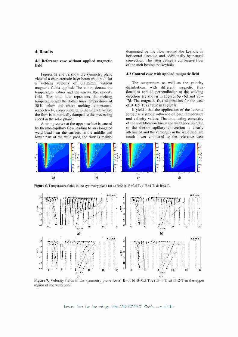
a) b) c) d)
Figure 6. Temperature fields in the symmetry plane for a) B=0, b) B=0.5 T, c) B=1 T, d) B=2 T.
a) b)
c) d)
Figure 7. Velocity fields in the symmetry plane for a) B=0, b) B=0.5 T, c) B=1 T, d) B=2 T in the upper
region of the weld pool.
4. Results
4.1 Reference case without applied magnetic
field
Figures 6a and 7a show the symmetry plane
view of a characteristic laser beam weld pool for
a welding velocity of 0.5 m/min without
magnetic fields applied. The colors denote the
temperature values and the arrows the velocity
field. The solid line represents the melting
temperature and the dotted lines temperatures of
50 K below and above melting temperature,
respectively, corresponding to the interval where
the flow is numerically damped to the processing
speed in the solid phase.
A strong vortex at the upper surface is caused
by thermo-capillary flow leading to an elongated
weld bead near the surface. In the middle and
lower part of the weld pool, the flow is mainly
dominated by the flow around the keyhole in
horizontal direction and additionally by natural
convection. The latter causes a convective flow
of the melt behind the keyhole.
4.2 Control case with applied magnetic field
The temperature as well as the velocity
distributions with different magnetic flux
densities applied perpendicular to the welding
direction are shown in Figures 6b - 6d and 7b –
7d. The magnetic flux distribution for the case
of B=0.5 T is shown in Figure 8.
It yields, that the application of the Lorentz
force has a strong influence on both temperature
and velocity values. The dominating convexity
of the solidification line at the weld pool rear due
to the thermo-capillary convection is clearly
attenuated and the velocities in the weld pool are
much lower compared to the reference case

without magnetic fields applied. Thus the
potential for severe spattering and melt ejections
is heavily degraded.
It becomes also clear, that the influence of
the thermo-capillary vortex at the upper surface
is the more limited to a thin surface layer the
higher the applied magnetic flux density is.
The velocity distribution for increasing
magnetic field at 2 mm below the upper surface
is shown in Figure 9. The velocities slow down
the larger the applied magnetic field and its
subsequent Lorentz forces are. Velocities below
the welding speed indicate a flow reversal from
recirculation mode (Figure 2a) to a flow parallel
aligned to the welding direction (Figure 2d).
The process of making the flow laminar can
be seen from the Hartmann number calculated at
a point 5 mm below the surface and 5 mm
behind the keyhole shown in Figure 10, with and
without consideration of the turbulent viscosity
being added to the dynamic viscosity material
property value. It yields, that beginning from a
point where the magnetic field is sufficient to
eliminate turbulence for the most part (B=0.5 T),
both curves are similar meaning that turbulence
has a vanishing influence on the flow behaviour.
Figure 11 shows the experimental
comparison to welding experiments with a fibre
laser with 16 kW output power. The laser focus
was 4 mm below the surface and the welding
velocity was 0.5 m/min. The experiments show
the same tendency as the simulations predict,
namely a narrowing of the weld cross section
and a lesser convexity of the solidification line as
well as a smoother surface topology due to
electromagnetic damping. Differences between
simulation and experiment can be justified by the
fact that the welding was done with AlMg3 alloy
whereas the calculation was accomplished with
pure aluminium due to a lack of availability of
Figure 8. Magnetic flux density distribution in the
weld symmetry plane for the case B=0.5 T.
Figure 9. Velocity distributions 2 mm below the
upper surface along the welding direction. Position
0 in x-direction corresponds to the laser spot
position.
Figure 10. Hartmann number calculated based on
the half weld pool width for increasing magnetic
flux densities with and without considering the
turbulent viscosity contribution.
Figure 11. Comparison between weld macro
sections perpendicular to the welding direction
from simulation and experiment for the reference
case (left) without applied Lorentz forces and the
case B=0.5 T (right).

high-temperature material data in the literature.
The material properties of both pure aluminium
and AlMg3 are slightly different.
5. Conclusions
The influence of a steady state magnetic field
perpendicular to the welding direction was
investigated numerically and experimentally.
The induced magnetic drag component
clearly lowers the influence of the Marangoni
stresses at the upper surface which is due to the
temperature-dependent surface tension.
It is shown, that the application of a magnetic
flux density of 0.5 T with a corresponding
Hartmann number around 104 leads to the local
development of a laminar flow regime due to the
magnetic induced drag component that is
directed against the original melt velocity thus
reducing turbulence.
Globally, the higher the magnetic field
applied, the more the convexity of the melting
isotherm due to thermo-capillary flow is
diminished in both the longitudinal as well as the
transversal cross sections which is advantageous
to avoid excessive mechanical stresses in the
welds after cooling-down. Lowering the melt
velocities is also favorable to prevent strong
spattering and melt ejections driven by the
dynamics in the weld pool.
6. References
1. Matsunawa A, Problems and solutions in deep
penetration laser welding, Sci. Technol. Weld.
Joi., 6, 351 – 354 (2001).
2. Radaj D, Welding Residual Stresses and
Distortion. Calculation and Measurement, DVS-
Verlag (2003).
3. Vollertsen F, Grünenwald S, Rethmeier M,
Gumenyuk A, Reisgen U, Olschok S, Welding of
thick steel plates using fibre lasers and GMAW,
Weld. World, 54, 62 – 70 (2010).
4. Dennis B H, Dulikravich G S, Magnetic field
suppression of melt flow in crystal growth, Int. J.
Heat Mass Transfer, 23, 269 – 277 (2002).
5. Velde O, Gritzki R, Grundmann R, Numerical
investigation of Lorentz force influenced
Marangoni convection relevant to aluminum
surface alloying, Int. J. Heat Mass Transfer, 44,
2751 – 2762 (2001).
6. Tang Z, Gatzen M, Influence on the dilution
by laser welding of aluminium with magnetic
stirring, Phys. Proc., 5, 125 – 137 (2010).
7. Vollertsen F, Thomy C, Magnetic stirring
during laser welding of aluminium, J. Laser
Appl., 18, 28 – 34 (2006).
8. Gatzen M, Tang Z, CFD-based model for melt
flow in laser beam welding of aluminium with
coaxial magnetic field, Phys. Proc., 5, 317 – 326
(2010).
9. Zhou J, Tsai H L, Effects of electromagnetic
force on melt flow and porosity prevention in
pulsed laser keyhole welding, Int. J. Heat Mass
Transfer, 50, 2217 – 2235 (2007).
10. Avilov V V, Gumenyuk A, Lammers M and
Rethmeier M, PA position full penetration high
power laser beam welding of up to 30 mm thick
AlMg3 plates using electromagnetic weld pool
support, Sci. Technol. Weld. Joi., 17, 128 – 133
(2012).
11. Bachmann M, Avilov V, Gumenyuk A and
Rethmeier M, Numerical simulation of full-
penetration laser beam welding of thick
aluminium plates with inductive support,
J. Phys. D: Appl. Phys., 45, 035201 (13pp)
(2012).
12. Kern M, Berger P, Hügel H, Magneto-Fluid
Dynamic Control of Seam Quality in CO2 Laser
Beam Welding, Weld. J., 3, 72-s–78-s (2000).
13. Mills, K C, Recommended Values of
Thermophysical Properties for Selected
Commercial Alloys, Woodhead Publishing
Ltd. (2002)
14. Keene, B J, Review of data for the surface
tension of pure metals, Int. Mater. Rev., 38, 157
– 192 (1993)
7. Acknowledgements
This work is supported by the Deutsche
Forschungsgemeinschaft (Bonn, Germany) under
Grant No. DFG GU 1211/2-1.
The authors would also like to thank the
German Federation of Industrial Research
Associations (AiF) and the German Federal
Ministry for Economics and Technology
(BMWi), for making this research possible by
funding the Project 17.265 N ‘Verbesserung der
Nahtqualität von lasergeschweißten Verbindun-
gen aus Aluminiumlegierungen mittels oszillie-
render Magnetfelder’ (‘Improving weld quality
of laser beam welded aluminium alloy joints by
oscillating magnetic fields’).


![1 Examples 3D Electromagnetic Simulation Magnetic quasi-static simulation [coreless liquid-cooled motor]](https://img.pdfslide.us/doc/110x75/56649ed55503460f94be601c/1-examples-3d-electromagnetic-simulation-magnetic-quasi-static-simulation-coreless.jpg)


![Magnetic quasi-static simulation [coreless liquid-cooled motor]](https://img.pdfslide.us/doc/110x75/56816864550346895ddeb859/magnetic-quasi-static-simulation-coreless-liquid-cooled-motor.jpg)