Embed Size (px)
Citation preview
Multi-physics modeling of Micro-Electro-Mechanical-Systems using
EMS for SOLIDWORKS
by
EMWorks Inc.
1
Majdi Elfahem
Senior Application Engineer

Agenda
• Overview about MEMS applications
• Challenges versus solutions
• Examples
• Conclusion
2
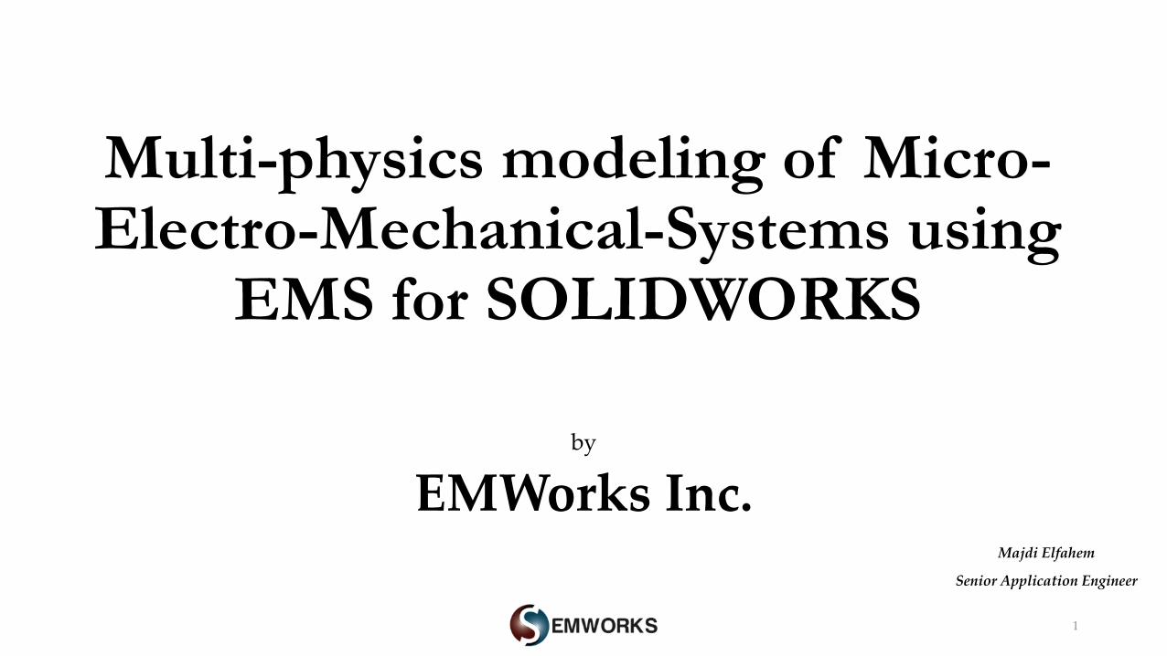
MEMS- Micro-Electro-Mechanical-Systems
3https://ieeexplore.ieee.org/document/6575798
https://www.arrow.com/en/research-and-events/articles/mems-and-iot-applications
https://ieeexplore.ieee.org/document/296932
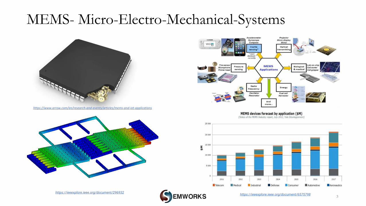
MEMS Applications: Challenges versus solutions
Challenges Solutions
4
Geometrical modeling
Materials modeling
Ohmic losses, electric and magnetic forces
Capacitance, inductance, resistance, etc
Multi-physics
Isotropic, anistropic, temperature dependent,etc
Electric and magnetic modules (static, harmonic
and transient)
Thermal and structural coupling
SOLIDWORKS
Design iterationsParameterization (geometrical and simulation variables )/ SW multi-
configurations
EMS for SOLIDWORKS
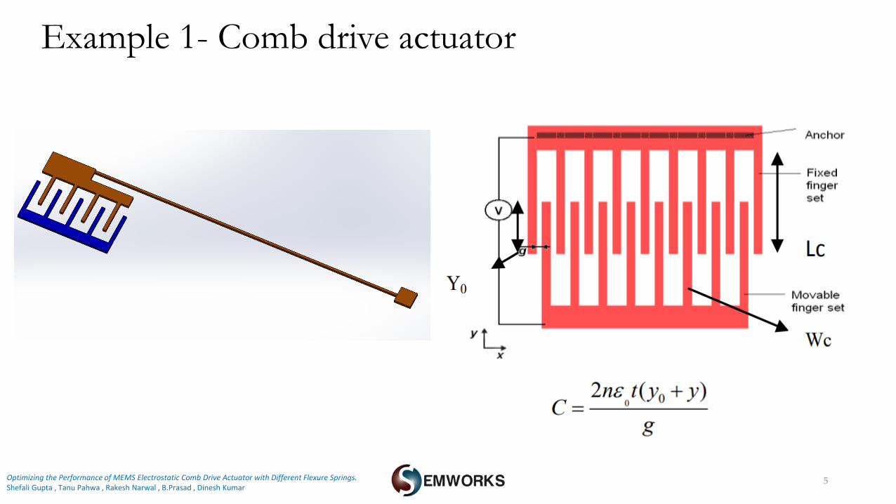
Example 1- Comb drive actuator
5Optimizing the Performance of MEMS Electrostatic Comb Drive Actuator with Different Flexure Springs.Shefali Gupta , Tanu Pahwa , Rakesh Narwal , B.Prasad , Dinesh Kumar
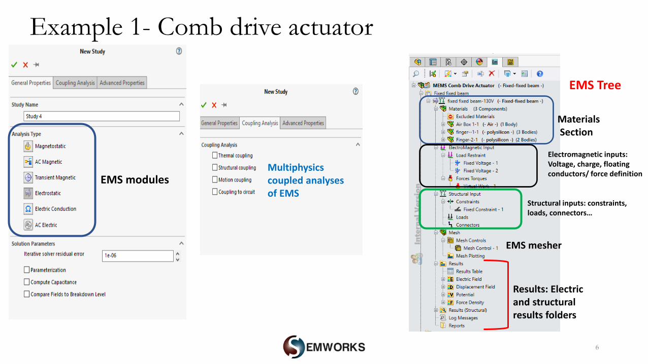
Example 1- Comb drive actuator
6
MaterialsSection
Electromagnetic inputs: Voltage, charge, floating conductors/ force definition
Structural inputs: constraints, loads, connectors…
EMS mesher
Results: Electric and structural results folders
EMS modules Multiphysicscoupled analyses of EMS
EMS Tree
7
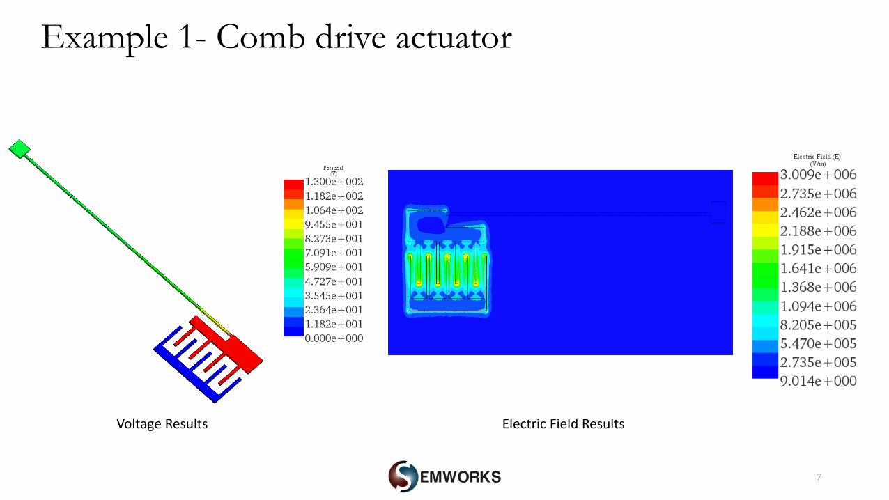
Example 1- Comb drive actuator
Voltage Results Electric Field Results
8
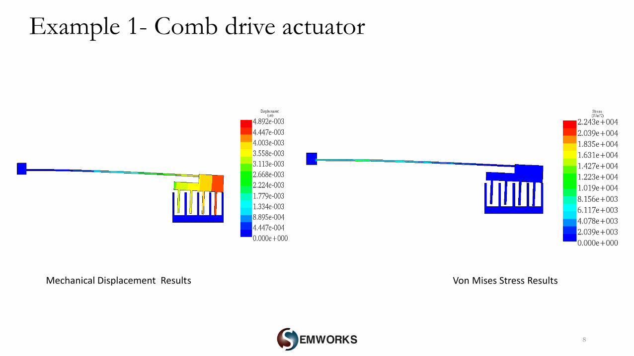
Example 1- Comb drive actuator
Mechanical Displacement Results Von Mises Stress Results
9
0.00E+00
5.00E+05
1.00E+06
1.50E+06
2.00E+06
2.50E+06
3.00E+06
3.50E+06
4.00E+06
0 20 40 60 80 100 120 140
Vo
n M
ise
s St
ress
(N
/m^2
)
Voltage (V)
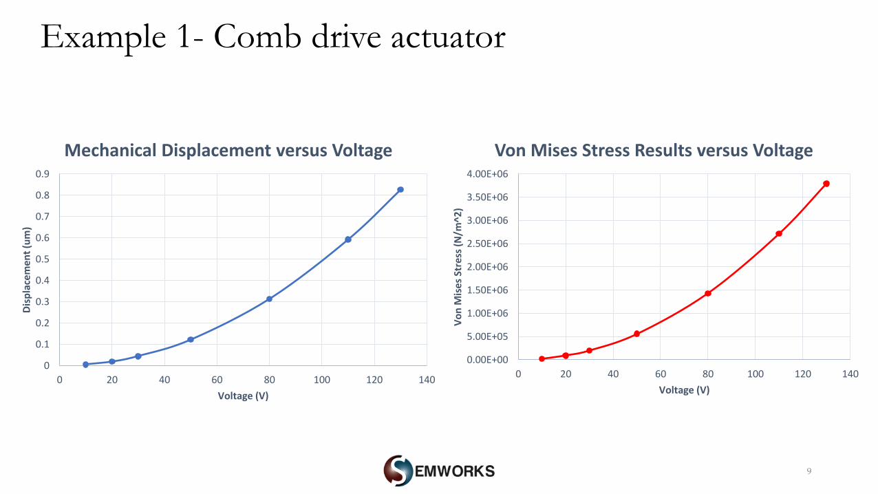
Von Mises Stress Results versus Voltage
0
0.1
0.2
0.3
0.4
0.5
0.6
0.7
0.8
0.9
0 20 40 60 80 100 120 140
Dis
pla
cem
ent
(um
)
Voltage (V)
Mechanical Displacement versus Voltage
Example 1- Comb drive actuator
10
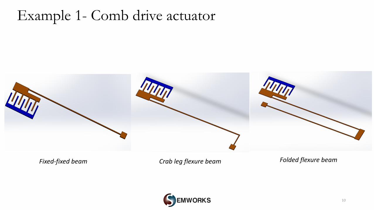
Example 1- Comb drive actuator
Fixed-fixed beam Crab leg flexure beam Folded flexure beam
11
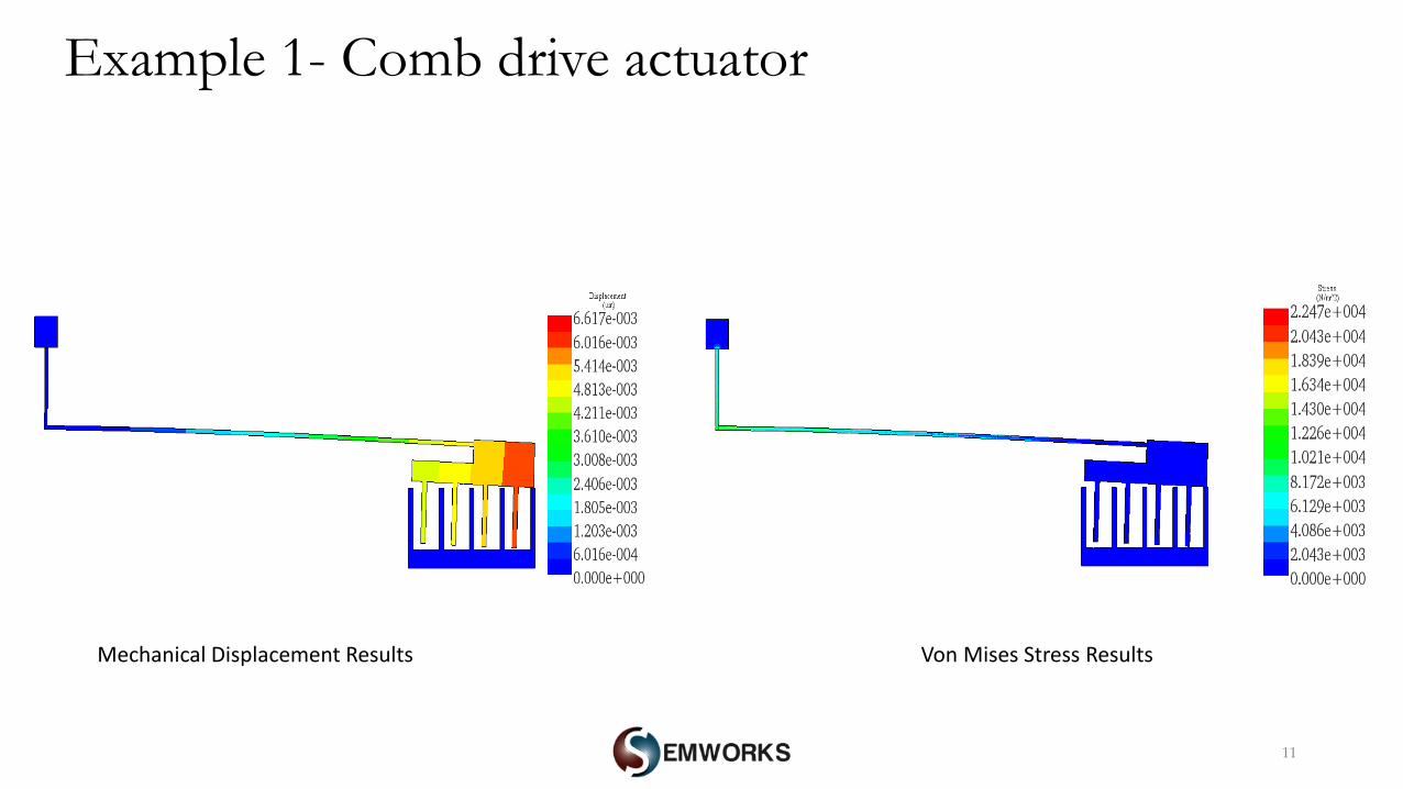
Example 1- Comb drive actuator
Mechanical Displacement Results Von Mises Stress Results
12
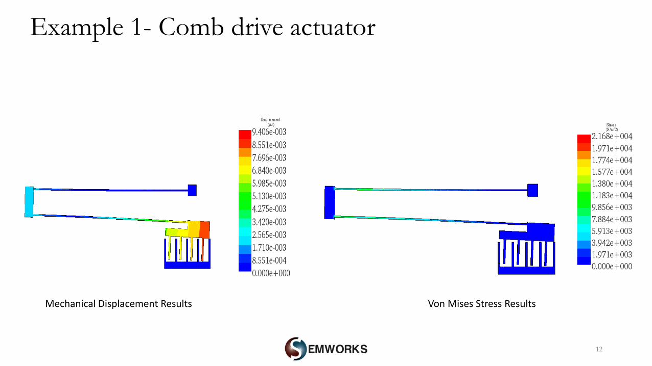
Example 1- Comb drive actuator
Mechanical Displacement Results Von Mises Stress Results
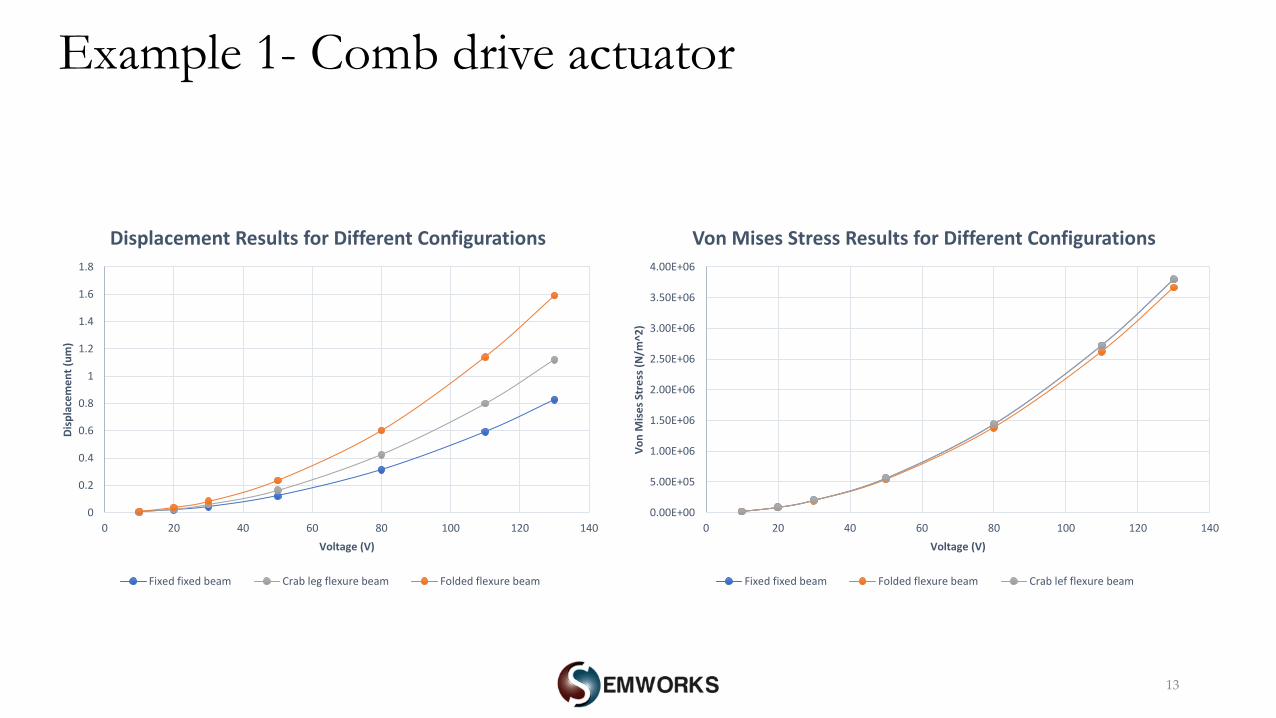
13
0.00E+00
5.00E+05
1.00E+06
1.50E+06
2.00E+06
2.50E+06
3.00E+06
3.50E+06
4.00E+06
0 20 40 60 80 100 120 140
Vo
n M
ise
s St
ress
(N
/m^2
)
Voltage (V)
Von Mises Stress Results for Different Configurations
Fixed fixed beam Folded flexure beam Crab lef flexure beam
Example 1- Comb drive actuator
0
0.2
0.4
0.6
0.8
1
1.2
1.4
1.6
1.8
0 20 40 60 80 100 120 140
Dis
pla
cem
en
t (u
m)
Voltage (V)
Displacement Results for Different Configurations
Fixed fixed beam Crab leg flexure beam Folded flexure beam
14
0
100
200
300
400
500
600
700
0 20 40 60 80 100 120 140
Elec
tro
stat
ic F
orc
e (
nN
)
Voltage (V)
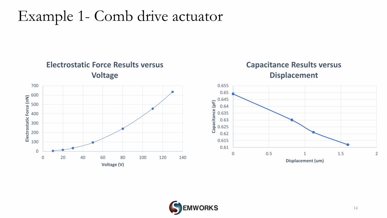
Electrostatic Force Results versus Voltage
0.61
0.615
0.62
0.625
0.63
0.635
0.64
0.645
0.65
0.655
0 0.5 1 1.5 2
Cap
acit
ance
(p
F)
Displacement (um)
Capacitance Results versus Displacement
Example 1- Comb drive actuator
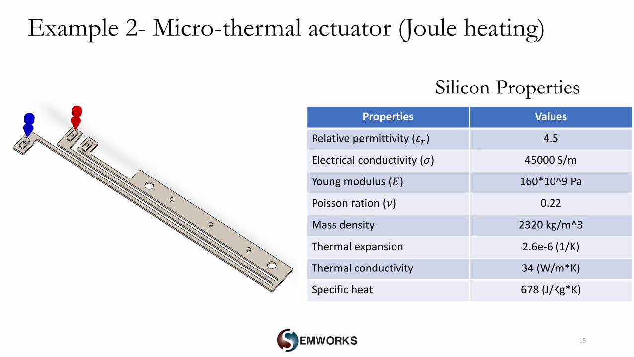
Example 2- Micro-thermal actuator (Joule heating)
15
Properties Values
Relative permittivity (𝜀𝑟) 4.5
Electrical conductivity (𝜎) 45000 S/m
Young modulus (𝛦) 160*10^9 Pa
Poisson ration (𝜈) 0.22
Mass density 2320 kg/m^3
Thermal expansion 2.6e-6 (1/K)
Thermal conductivity 34 (W/m*K)
Specific heat 678 (J/Kg*K)
Silicon Properties
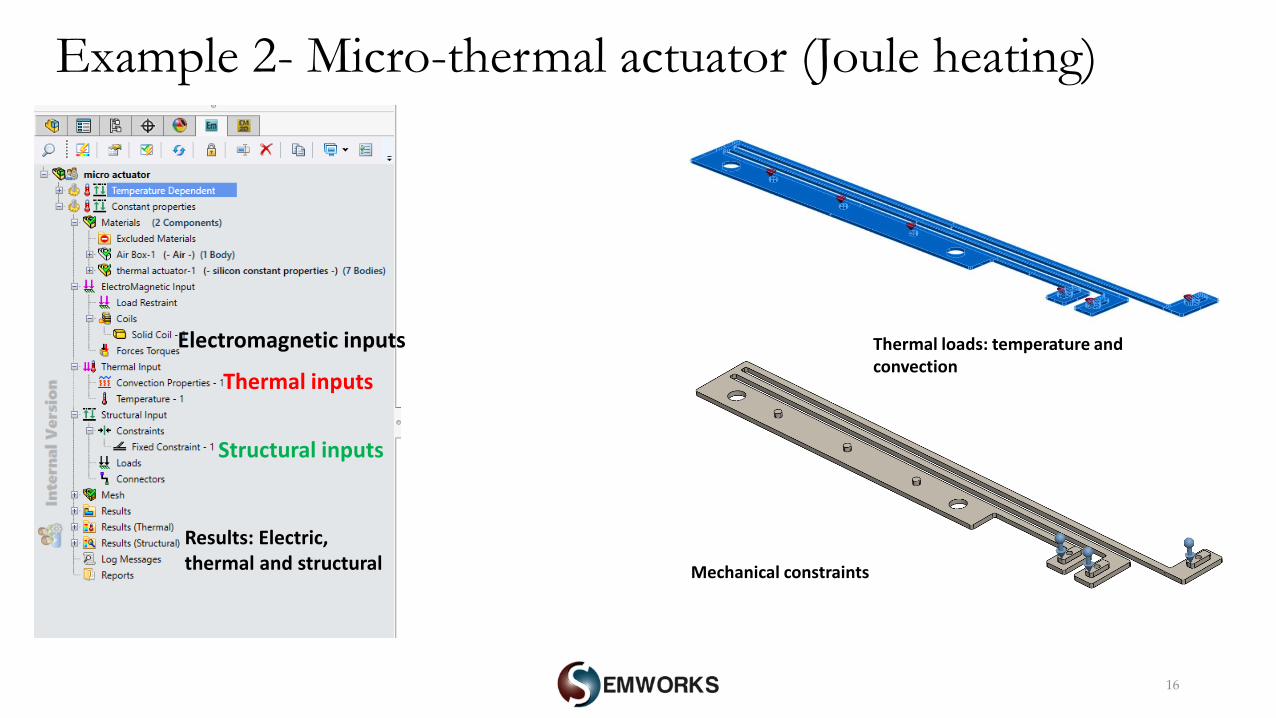
Example 2- Micro-thermal actuator (Joule heating)
16
Electromagnetic inputs
Thermal inputs
Structural inputs
Results: Electric, thermal and structural
Thermal loads: temperature and convection
Mechanical constraints
17
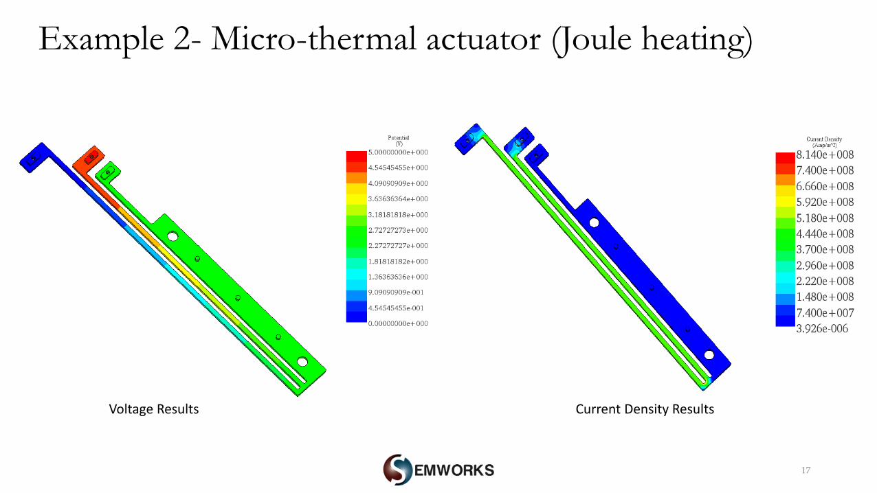
Example 2- Micro-thermal actuator (Joule heating)
Current Density ResultsVoltage Results
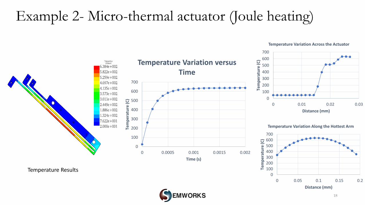
18
0
100
200
300
400
500
600
700
0 0.0005 0.001 0.0015 0.002
Tem
per
atu
re (
C)
Time (s)
Temperature Variation versus Time
Example 2- Micro-thermal actuator (Joule heating)
0
100
200
300
400
500
600
700
0 0.01 0.02 0.03
Tem
pe
ratu
re (
C)
Distance (mm)
Temperature Variation Across the Actuator
0
100
200
300
400
500
600
700
0 0.05 0.1 0.15 0.2
Tem
per
atu
re (
C)
Distance (mm)
Temperature Variation Along the Hottest Arm
Temperature Results
19
0
0.5
1
1.5
2
2.5
3
0
10000000
20000000
30000000
40000000
50000000
60000000
70000000
80000000
0 0.0005 0.001 0.0015 0.002 0.0025
Dis
pla
cem
ent
(um
)
Vo
n M
ise
s St
ress
(N
/m^2
)
Time (s)
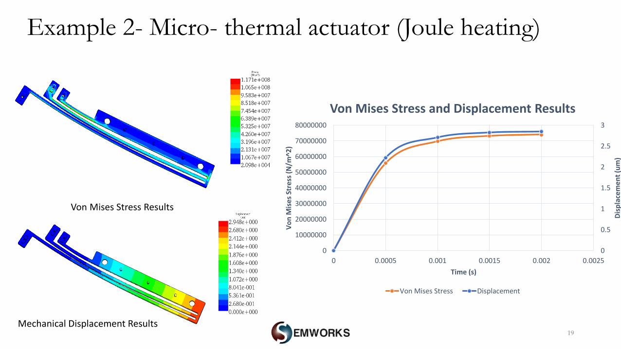
Von Mises Stress and Displacement Results
Von Mises Stress Displacement
Example 2- Micro- thermal actuator (Joule heating)
Von Mises Stress Results
Mechanical Displacement Results
20
0.00E+00
2.00E+07
4.00E+07
6.00E+07
8.00E+07
1.00E+08
1.20E+08
1.40E+08
0
0.5
1
1.5
2
2.5
3
3.5
0 1 2 3 4 5 6
Voltage (V)
Vo
n M
ise
s St
ress
(N
/m^2
)
Dis
pla
cem
ent
(um
)
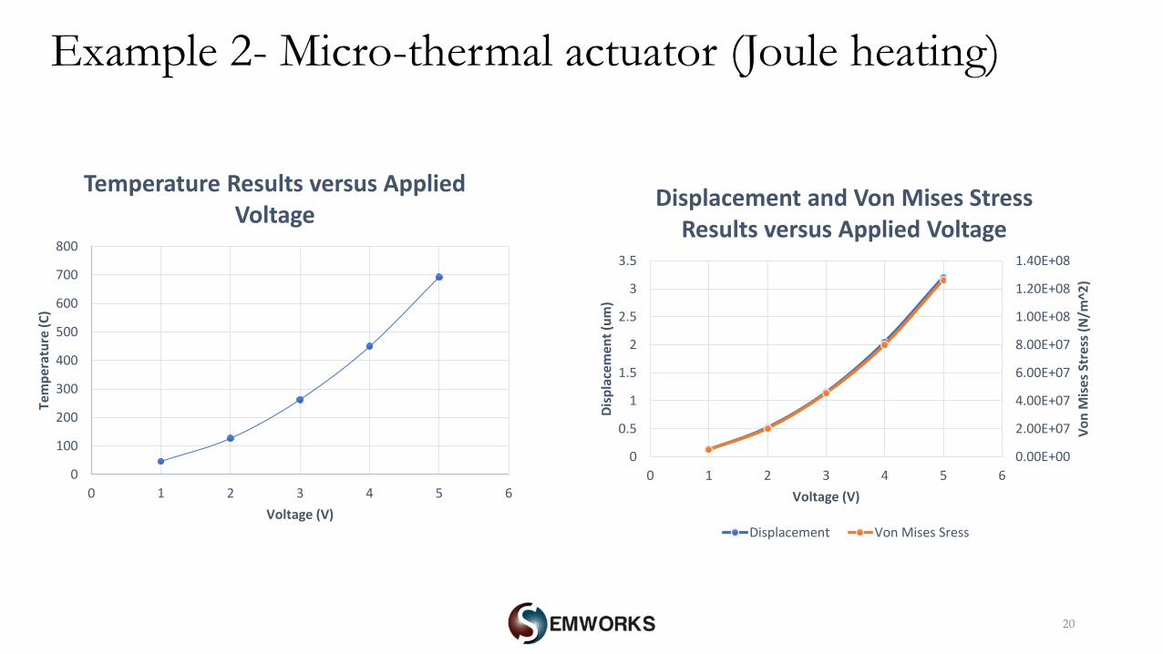
Displacement and Von Mises Stress Results versus Applied Voltage
Displacement Von Mises Sress
0
100
200
300
400
500
600
700
800
0 1 2 3 4 5 6
Tem
pe
ratu
re (
C)
Voltage (V)
Temperature Results versus Applied Voltage
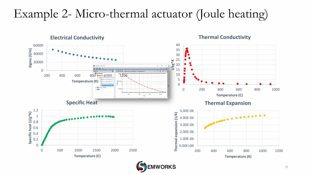
Example 2- Micro-thermal actuator (Joule heating)
21
0.00E+00
1.00E-06
2.00E-06
3.00E-06
4.00E-06
5.00E-06
200 400 600 800 1000 1200Ther
mal
exp
ansi
on
(1
/K)
Temperature (K)
Thermal Expansion
0
5
10
15
20
25
30
35
40
0 200 400 600 800 1000
J/kg
*K
Temperature (C)
Thermal Conductivity
0
20000
40000
60000
200 400 600 800 1000 1200
Sigm
a (S
/m)
Temperature (K)
Electrical Conductivity
0
0.2
0.4
0.6
0.8
1
1.2
0 500 1000 1500 2000 2500
Spe
cifi
c h
eat
(J/
g*K
)
Temperature (C)
Specific Heat
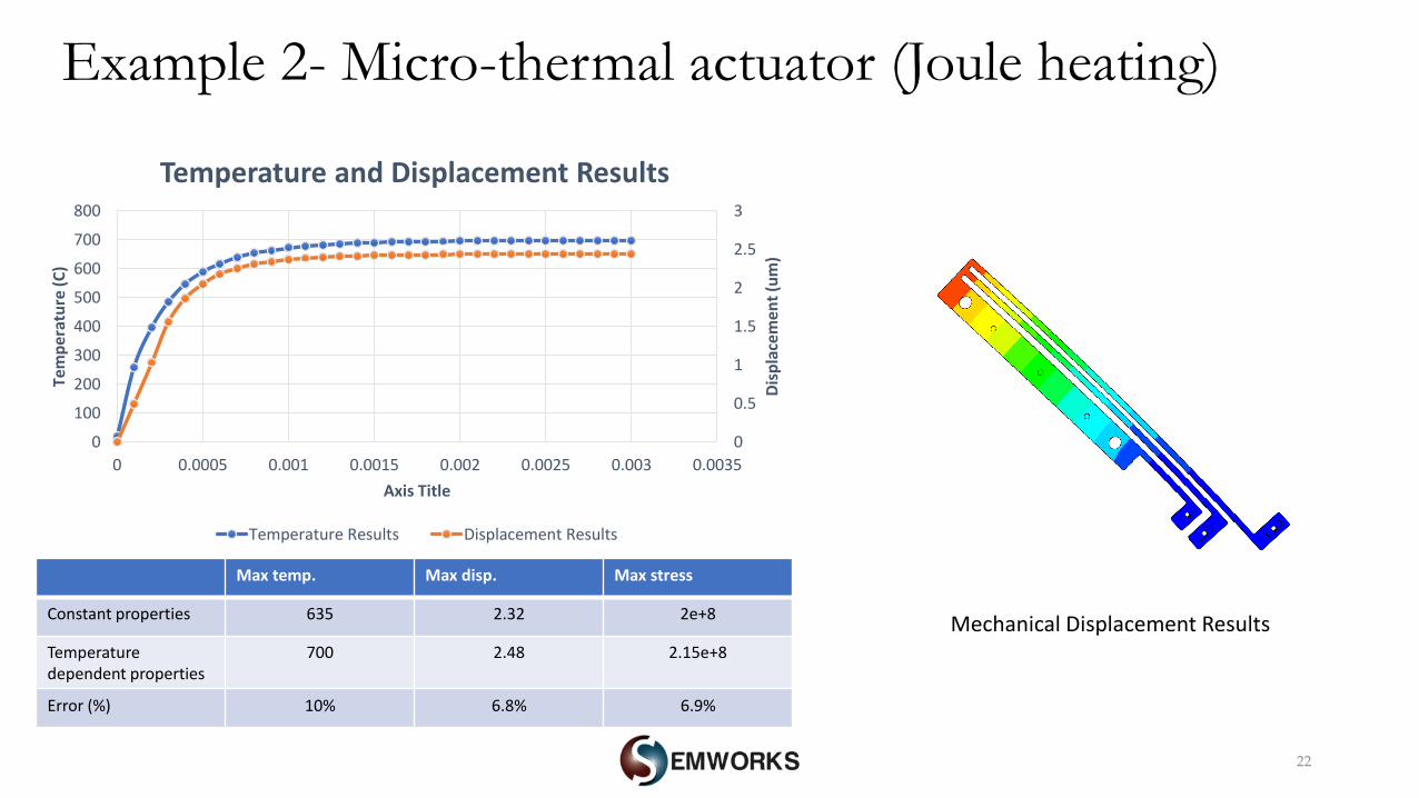
Example 2- Micro-thermal actuator (Joule heating)
22
0
0.5
1
1.5
2
2.5
3
0
100
200
300
400
500
600
700
800
0 0.0005 0.001 0.0015 0.002 0.0025 0.003 0.0035
Dis
pla
cem
ent
(um
)
Tem
per
atu
re (
C)
Axis Title
Temperature and Displacement Results
Temperature Results Displacement Results
Max temp. Max disp. Max stress
Constant properties 635 2.32 2e+8
Temperature dependent properties
700 2.48 2.15e+8
Error (%) 10% 6.8% 6.9%
Example 2- Micro-thermal actuator (Joule heating)
Mechanical Displacement Results
23
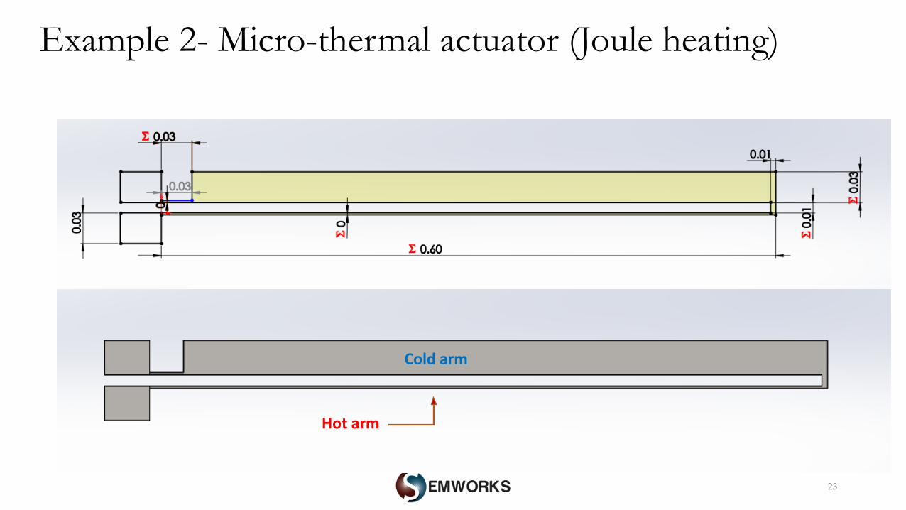
Cold arm
Hot arm
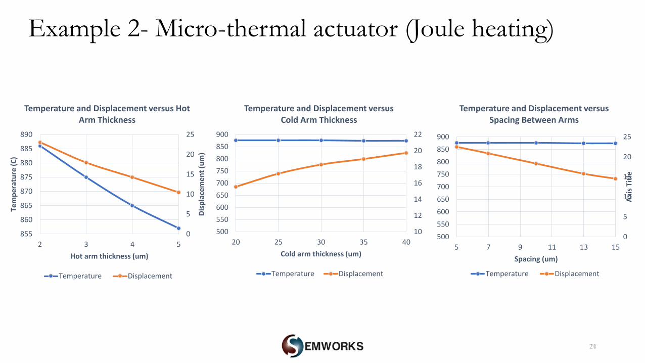
Example 2- Micro-thermal actuator (Joule heating)
24
0
5
10
15
20
25
855
860
865
870
875
880
885
890
2 3 4 5
Dis
pla
cem
ent
(um
)
Tem
per
atu
re (
C)
Hot arm thickness (um)
Temperature and Displacement versus Hot Arm Thickness
Temperature Displacement
10
12
14
16
18
20
22
500
550
600
650
700
750
800
850
900
20 25 30 35 40
Cold arm thickness (um)
Temperature and Displacement versus Cold Arm Thickness
Temperature Displacement
0
5
10
15
20
25
500
550
600
650
700
750
800
850
900
5 7 9 11 13 15
Axi
s Ti
tle
Spacing (um)
Temperature and Displacement versus Spacing Between Arms
Temperature Displacement
Example 2- Micro-thermal actuator (Joule heating)
25
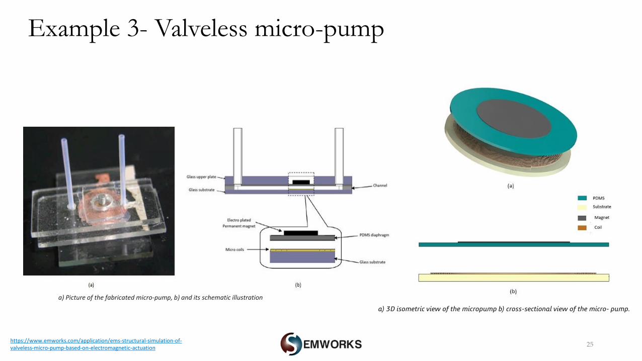
Example 3- Valveless micro-pump
https://www.emworks.com/application/ems-structural-simulation-of-valveless-micro-pump-based-on-electromagnetic-actuation
a) Picture of the fabricated micro-pump, b) and its schematic illustration
a) 3D isometric view of the micropump b) cross-sectional view of the micro- pump.
26
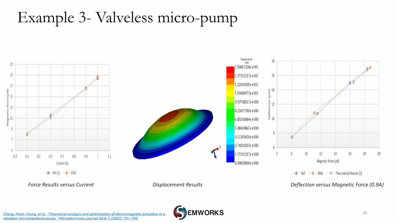
Example 3- Valveless micro-pump
Chang, Hsien-Tsung, et al. "Theoretical analysis and optimization of electromagnetic actuation in a valveless microimpedance pump." Microelectronics journal 38.6-7 (2007): 791-799.
Force Results versus Current Displacement Results Deflection versus Magnetic Force (0.9A)
27
Conclusion
o EMS was used to study different MEMS devices including electric and magnetic applications
o Electrostatic and magnetic forces were computed by EMS
o Ohmic losses and capacitance results were calculated by EMS
o Temperature variation and structural deformation were estimated versus different situations and
scenarios
o EMS results were compared to experimental and analytical results