Embed Size (px)
Citation preview
Preface, Contents
Introduction 1
Functionality 2
Commissioning 3
MP270 Operation 4
Operating Special Screen Objects 5
System Settings 6
Installation 7
Unit Description 8
Options 9
Maintenance/Upkeep 10
Appendices
A
F
Glossary, Index
Release 01/99
6AV6591–1DB01–0AB0
Multi PanelMP270
Equipment Manual
SIMATIC HMI
Index-2MP270 Equipment Manual
Release 01/99
!Warning
indicates that death, severe personal injury or substantial property damage can result if proper precau-tions are not taken.
!Caution
indicates that minor personal injury or property damage can result if proper precautions are not taken.
Note
draws your attention to particularly important information on the product, handling the product, or to aparticular part of the documentation.
Qualified PersonnelEquipment may be commissioned and operated only by qualified personnel . Qualified personnel withinthe meaning of the safety notices in this manual are persons who are authorized to commission, groundand identify equipment, systems and circuits in accordance with safety engineering standards.
Correct UsageNote the following:
!Warning
The equipment may be used only for the applications stipulated in the catalog and in the technical descrip-tion and only in conjunction with other equipment and components recommended or approved by Sie-mens.
Startup must not take place until it is established that the machine, which is to accommodate this compo-nent, is in conformity with the guideline 89/392/EEC.
Faultless and safe operation of the product presupposes proper transportation, proper storage, erectionand installation as well as careful operation and maintenance.
TrademarksSIMATIC�, ProTool/Lite�, ProTool� and ProTool/Pro� are registered trademarks of Siemens AG.
Some of the other designations used in these documents are also registered trademarks; the owner’srights may be violated if they are used be third parties for their own purposes.
ImpressumEditor and Publisher: A&D PT1.
Safety GuidelinesThis manual contains notices which you should observe to ensure your own personal safety, as well as toprotect the product and connected equipment. These notices are highlighted in the manual by a warningtriangle and are marked as follows according to the level of danger:
We have checked the contents of this manual for agreement with the hard-ware and software described. Since deviations cannot be precluded entirely,we cannot guarantee full agreement. However, the data in this manual arereviewed regularly and any necessary corrections included in subsequenteditions. Suggestions for improvement are welcomed.
Disclaimer of LiabilityCopyright Siemens AG 1999 All rights reserved
The reproduction, transmission or use of this document or its contents is notpermitted without express written authority. Offenders will be liable fordamages. All rights, including rights created by patent grant or registration ofan utility model or design, are reserved.
Siemens AGBereich Automatisierungs- und AntriebstechnikBedienen und BeobachtenPostfach 4848, D-90327 Nuernberg
� Siemens AG 1999Technical data subject to change.
Siemens Aktiengesellschaft Order no: 6AV6591–1DB01–0AB0
iMP270 Equipment ManualRelease 01/99
Preface
This manual
The MP270 equipment manual is part of the SIMATIC HMI documentation. Itprovides operation, installation, configuration and system personnel withinformation concerning installation, functionality, operation and technical design ofthe MP270.
An overview of the entire SIMATIC HMI documentation is provided in Appendix E.
Organization of the manual
The MP270 equipment manual is organized into the following chapters:
Chapter Contents
1 - 2 Overview of features and functional scope of the MP270.
3 - 6 Commissioning, operation and system settings.
7 - 10 Mechanical and electrical installation, unit description, retrofitting ofoptions as well as maintenance and upkeep of the MP270.
Appendix � Technical Data
� Interface Assignments
� System Messages
� ESD Guidelines
� SIMATIC HMI Documentation
� Siemens Worldwide
Preface
iiMP270 Equipment Manual
Release 01/99
Conventions
The following cionventions are used throughout this manual:
Motor off Text in the operating unit display is presented in thistypewriter font.
Tag Symbolic names representing tag values on the screen arepresented in this italic typewriter font.
Screens Functions available for selection are presented in this italicfont.
ESC The names of keys and buttons are displayed in a differentfont.
History
The various releases of this manual correspond to the following versions of theProTool configuration software:
Release Comment ProTool version
01/99 First release of the MP270 equipmentmanual.
From V 5.1
Other support
In the case of technical queries, please contact the Siemens representatives in thesubsidiaries and branches responsible for your area. Refer to Appendix F for a listof addresses.
Preface
iiiMP270 Equipment ManualRelease 01/99
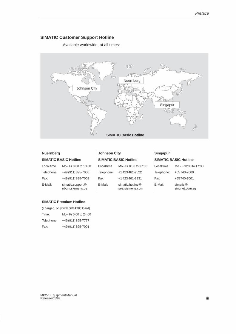
SIMATIC Customer Support Hotline
Available worldwide, at all times:
Johnson City
Nuernberg
Singapur
SIMATIC Basic Hotline
Nuernberg Johnson City Singapur
SIMATIC BASIC Hotline SIMATIC BASIC Hotline SIMATIC BASIC Hotline
Local time Mo - Fr 8:00 to 18:00 Local time Mo - Fr 8:00 to 17:00 Local time Mo - Fr 8:30 to 17:30
Telephone: +49 (911) 895-7000 Telephone: +1 423 461-2522 Telephone: +65 740-7000
Fax: +49 (911) 895-7002 Fax: +1 423 461-2231 Fax: +65 740-7001
E-Mail: [email protected]
E-Mail: [email protected]
E-Mail: [email protected]
SIMATIC Premium Hotline
(charged, only with SIMATIC Card)
Time: Mo - Fr 0:00 to 24:00
Telephone: +49 (911) 895-7777
Fax: +49 (911) 895-7001
Preface
ivMP270 Equipment Manual
Release 01/99
SIMATIC Customer Online Services
SIMATIC Customer Support offers comprehensive additional informationconcerning SIMATIC products through its Online services as follows:
� Up-to-date general information is provided
– in Internet under http://www.ad.siemens.de/simatic
– via the Fax-Polling under 08765–93 02 77 95 00
� Up-to-date product information and downloads for practical use can be found:
– in Internet under http://www.ad.siemens.de/support/html–00/
– via the Bulletin Board System (BBS) in Nuernberg (SIMATIC CustomerSupport Mailbox) under +49 (911) 895–7100
In order to contact the mailbox, please use a modem with up to 28.8 kBaud(V.34) capacity. Set the parameters as follows: 8, N, 1, ANSI, or dial forconnection via ISDN (x.75, 64 kBit).
Preface
vMP270 Equipment ManualRelease 01/99
Abbreviations
The abbreviations used in this equipment manual have the following meaning:
AG Automation unit
AM Alarm message
ANSI American National Standards Institute
AS 511 Protocol of the PU interface on the SIMATIC S5
ASCII American Standard Code for Information Interchange
BHB User’s guide
EM Event message
CCFL Cold Cathode Fluorescence Lamp
CF Compact Flash
CPU Central Processing Unit
DIL Dual-In-Line (housing design)
DRAM Dynamic Random Access Memory
EMC Elecromagnetic Compatibility
EPROM Electric Programable Read Only Memory
ESD Electrostatic Sensitive Device
GHB Equipment manual
HMI Human Machine Interface
IF Interface
JEIDA Japan Electronic Industry Development Association
LCD Liquid Crystal Display
LED Light Emitting Diode
MP Multi Panel
MPI Multipoint Interface (SIMATIC S7)
OP Operator Panel
PC Personal Computer
PCL Printer Control Language
PCMCIA Personal Computer Memory Card International Association
PLC Programmable Logic Control
PPI Point to Point Interface (SIMATIC S7)
PU Programming Unit
SRAM Static Random Access Memory
STN Super Twisted Nematic
TFT Thin Film Transistor
TTL Transistor-Transistor Logic
A list of all the special terms used with explanation is provided in the Glossary atthe end of this manual.

Preface
viMP270 Equipment Manual
Release 01/99
viiMP270 Equipment ManualRelease 01/99
Contents
1 Introduction 1-1. . . . . . . . . . . . . . . . . . . . . . . . . . . . . . . . . . . . . . . . . . . . . . . . . . . . . . . . . . . .
2 Functionality 2-1. . . . . . . . . . . . . . . . . . . . . . . . . . . . . . . . . . . . . . . . . . . . . . . . . . . . . . . . . . .
3 Commissioning 3-1. . . . . . . . . . . . . . . . . . . . . . . . . . . . . . . . . . . . . . . . . . . . . . . . . . . . . . . .
3.1 Initial Startup 3-2. . . . . . . . . . . . . . . . . . . . . . . . . . . . . . . . . . . . . . . . . . . . . . . . . . .
3.2 Recommissioning 3-3. . . . . . . . . . . . . . . . . . . . . . . . . . . . . . . . . . . . . . . . . . . . . . .
3.3 Test Configuration 3-4. . . . . . . . . . . . . . . . . . . . . . . . . . . . . . . . . . . . . . . . . . . . . . .
4 MP270 Operation 4-1. . . . . . . . . . . . . . . . . . . . . . . . . . . . . . . . . . . . . . . . . . . . . . . . . . . . . . .
4.1 Integrated Keyboard 4-1. . . . . . . . . . . . . . . . . . . . . . . . . . . . . . . . . . . . . . . . . . . . .
4.2 Entering Values 4-5. . . . . . . . . . . . . . . . . . . . . . . . . . . . . . . . . . . . . . . . . . . . . . . . . 4.2.1 Enter numeric values 4-6. . . . . . . . . . . . . . . . . . . . . . . . . . . . . . . . . . . . . . . . . . . . 4.2.2 Enter alphanumeric values 4-7. . . . . . . . . . . . . . . . . . . . . . . . . . . . . . . . . . . . . . . 4.2.3 Enter symbolic values 4-8. . . . . . . . . . . . . . . . . . . . . . . . . . . . . . . . . . . . . . . . . . . .
4.3 Call Help Text 4-9. . . . . . . . . . . . . . . . . . . . . . . . . . . . . . . . . . . . . . . . . . . . . . . . . . .
4.4 Operating Screens 4-10. . . . . . . . . . . . . . . . . . . . . . . . . . . . . . . . . . . . . . . . . . . . . .
5 Operating Special Screen Objects 5-1. . . . . . . . . . . . . . . . . . . . . . . . . . . . . . . . . . . . . . .
5.1 Overview of Screen Objects 5-1. . . . . . . . . . . . . . . . . . . . . . . . . . . . . . . . . . . . . .
5.2 Messages 5-4. . . . . . . . . . . . . . . . . . . . . . . . . . . . . . . . . . . . . . . . . . . . . . . . . . . . . . 5.2.1 Message Line 5-6. . . . . . . . . . . . . . . . . . . . . . . . . . . . . . . . . . . . . . . . . . . . . . . . . . . 5.2.2 Message Window 5-7. . . . . . . . . . . . . . . . . . . . . . . . . . . . . . . . . . . . . . . . . . . . . . . 5.2.3 Message Page 5-8. . . . . . . . . . . . . . . . . . . . . . . . . . . . . . . . . . . . . . . . . . . . . . . . . . 5.2.4 Message Buffer 5-9. . . . . . . . . . . . . . . . . . . . . . . . . . . . . . . . . . . . . . . . . . . . . . . . . 5.2.5 Message View 5-10. . . . . . . . . . . . . . . . . . . . . . . . . . . . . . . . . . . . . . . . . . . . . . . . . .
5.3 Trend Graphics 5-11. . . . . . . . . . . . . . . . . . . . . . . . . . . . . . . . . . . . . . . . . . . . . . . . .
5.4 Status/Force 5-14. . . . . . . . . . . . . . . . . . . . . . . . . . . . . . . . . . . . . . . . . . . . . . . . . . . .
5.5 Date/Time 5-16. . . . . . . . . . . . . . . . . . . . . . . . . . . . . . . . . . . . . . . . . . . . . . . . . . . . . .
5.6 Password Protection 5-18. . . . . . . . . . . . . . . . . . . . . . . . . . . . . . . . . . . . . . . . . . . . . 5.6.1 Logging in and out of the MP270 5-19. . . . . . . . . . . . . . . . . . . . . . . . . . . . . . . . . . 5.6.2 Password management 5-20. . . . . . . . . . . . . . . . . . . . . . . . . . . . . . . . . . . . . . . . . .
Contents
viiiMP270 Equipment Manual
Release 01/99
6 System Settings 6-1. . . . . . . . . . . . . . . . . . . . . . . . . . . . . . . . . . . . . . . . . . . . . . . . . . . . . . . .
6.1 Set Language 6-2. . . . . . . . . . . . . . . . . . . . . . . . . . . . . . . . . . . . . . . . . . . . . . . . . . .
6.2 Setting an Operating Mode 6-3. . . . . . . . . . . . . . . . . . . . . . . . . . . . . . . . . . . . . . .
6.3 Screen Settings 6-4. . . . . . . . . . . . . . . . . . . . . . . . . . . . . . . . . . . . . . . . . . . . . . . . .
6.4 Control Panel Settings 6-5. . . . . . . . . . . . . . . . . . . . . . . . . . . . . . . . . . . . . . . . . . .
7 Installation 7-1. . . . . . . . . . . . . . . . . . . . . . . . . . . . . . . . . . . . . . . . . . . . . . . . . . . . . . . . . . . . .
7.1 Mechanical Installation 7-2. . . . . . . . . . . . . . . . . . . . . . . . . . . . . . . . . . . . . . . . . . .
7.2 Electrical Installation 7-4. . . . . . . . . . . . . . . . . . . . . . . . . . . . . . . . . . . . . . . . . . . . . 7.2.1 Connect configuration computer 7-7. . . . . . . . . . . . . . . . . . . . . . . . . . . . . . . . . . . 7.2.2 Connect PLC 7-8. . . . . . . . . . . . . . . . . . . . . . . . . . . . . . . . . . . . . . . . . . . . . . . . . . . 7.2.3 Connect printer 7-10. . . . . . . . . . . . . . . . . . . . . . . . . . . . . . . . . . . . . . . . . . . . . . . . .
8 Unit Description 8-1. . . . . . . . . . . . . . . . . . . . . . . . . . . . . . . . . . . . . . . . . . . . . . . . . . . . . . . .
8.1 Dimensions 8-2. . . . . . . . . . . . . . . . . . . . . . . . . . . . . . . . . . . . . . . . . . . . . . . . . . . . .
8.2 Operating and display elements 8-3. . . . . . . . . . . . . . . . . . . . . . . . . . . . . . . . . . .
8.3 Connection elements 8-4. . . . . . . . . . . . . . . . . . . . . . . . . . . . . . . . . . . . . . . . . . . .
8.4 Communication Options 8-5. . . . . . . . . . . . . . . . . . . . . . . . . . . . . . . . . . . . . . . . . .
8.5 Labeling Function Keys 8-6. . . . . . . . . . . . . . . . . . . . . . . . . . . . . . . . . . . . . . . . . .
9 Options 9-1. . . . . . . . . . . . . . . . . . . . . . . . . . . . . . . . . . . . . . . . . . . . . . . . . . . . . . . . . . . . . . . .
9.1 Memory Cards 9-2. . . . . . . . . . . . . . . . . . . . . . . . . . . . . . . . . . . . . . . . . . . . . . . . . .
9.2 Backup Battery 9-4. . . . . . . . . . . . . . . . . . . . . . . . . . . . . . . . . . . . . . . . . . . . . . . . .
10 Maintenance/Upkeep 10-1. . . . . . . . . . . . . . . . . . . . . . . . . . . . . . . . . . . . . . . . . . . . . . . . . . . .
10.1 Clean Screen and Keyboard Foil 10-1. . . . . . . . . . . . . . . . . . . . . . . . . . . . . . . . . .
10.2 Replacing the Optional Backup Battery 10-2. . . . . . . . . . . . . . . . . . . . . . . . . . . . .
Appendices
A Technical Data A-1. . . . . . . . . . . . . . . . . . . . . . . . . . . . . . . . . . . . . . . . . . . . . . . . . . . . . . . . .
B Interface Assignment B-1. . . . . . . . . . . . . . . . . . . . . . . . . . . . . . . . . . . . . . . . . . . . . . . . . . .
C System Messages C-1. . . . . . . . . . . . . . . . . . . . . . . . . . . . . . . . . . . . . . . . . . . . . . . . . . . . . .
D ESD-Guidelines D-1. . . . . . . . . . . . . . . . . . . . . . . . . . . . . . . . . . . . . . . . . . . . . . . . . . . . . . . .
E SIMATIC HMI Documentation E-1. . . . . . . . . . . . . . . . . . . . . . . . . . . . . . . . . . . . . . . . . . . .
F Siemens Worldwide F-1. . . . . . . . . . . . . . . . . . . . . . . . . . . . . . . . . . . . . . . . . . . . . . . . . . . .
1-1MP270 Equipment ManualRelease 01/99
Introduction
New product category
The SIMATIC Multi Panel MP270 belongs to the new product category called“Multifunctional Platform” and is positioned in the product hierarchy betweenclassic components such as operator panels and PLC on the one hand, andindustrial computers on the other. The multifunctional platform combines therobustness of the dedicated hardware solutions with the flexibility of the PC world.
The new product category combines functions, such as visualization and control,based on the operating system Microsoft� Windows� CE.
Multi Panels provide the following additional performance features as compared tothe proven SIMATIC operating units:
� Archiving process values and messages
� Dynamic use of screen objects (e.g. moving objects)
� Simulation of the configuration on the PC/PG
� Large selection of pre-finished screen objects available during configuration(e.g. message view, Status/Force, buttons, selection fields)
� Creation of vector graphics in ProTool without the use of a graphic editor
Area of use of the MP270
The MP270 has been conceived for easy machine operation and monitoring. Itprovides a realistic graphical representation of the machine or system to bemonitored. Its area of use includes implementation in machine and apparatusconstruction as well as in the packing and electronics industry.
The high degree of protection (IP65 on the front side) and non-implementation ofmoving storage media, such as hard disks and floppy disks, ensure the MP270 isalso suitable for use in rough industrial environments and directly on site on therespective machine.
Installation locations for the MP270 include:
� Panels/Consoles
� 19’’ cabinets/racks
Due to the fact that the MP270 is equipped with high performance basic hardwareand has a minimum installation depth means that it fulfills all the requirements foroperation in the vicinity of the machine.
1
Introduction
1-2MP270 Equipment Manual
Release 01/99
Easy to operate and observe
The MP270 enables operating statuses, current process values and errorsconcerning a connected PLC to be graphically displayed and the relevant machineor system to be easily monitored and operated. Display and operation of theMP270 can be adapted optimally for the respective process requirenments byusing the configuration software ProTool (from version 5.1).
The MP270 can be used to:
� control and monitor the process by means of the menu system. Setpoint valuesor control element settings, for instance, can be modified by entering values oractivating configured function keys;
� display processes, machines and systems on fully-graphic, dynamic screens;
� visualize operating and alarm messages and process tags, e.g. in output fields,bar graphs, trend curves or status settings;
� intervene directly in the running process by using the integrated keyboard.
Configuration using ProTool
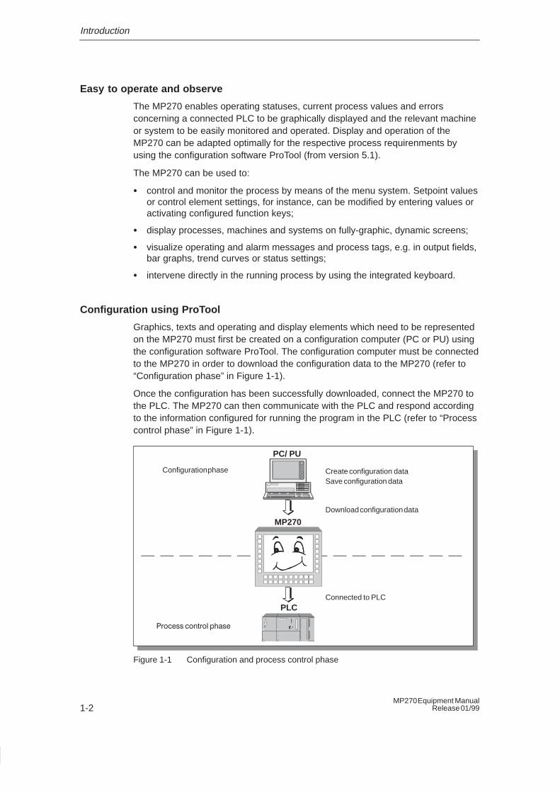
Graphics, texts and operating and display elements which need to be representedon the MP270 must first be created on a configuration computer (PC or PU) usingthe configuration software ProTool. The configuration computer must be connectedto the MP270 in order to download the configuration data to the MP270 (refer to“Configuration phase” in Figure 1-1).
Once the configuration has been successfully downloaded, connect the MP270 tothe PLC. The MP270 can then communicate with the PLC and respond accordingto the information configured for running the program in the PLC (refer to “Processcontrol phase” in Figure 1-1).
Create configuration data Save configuration data
Download configuration data
Connected to PLC
Configuration phase
Process control phase
PC/ PU
PLC
MP270
Figure 1-1 Configuration and process control phase
Introduction
1-3MP270 Equipment ManualRelease 01/99
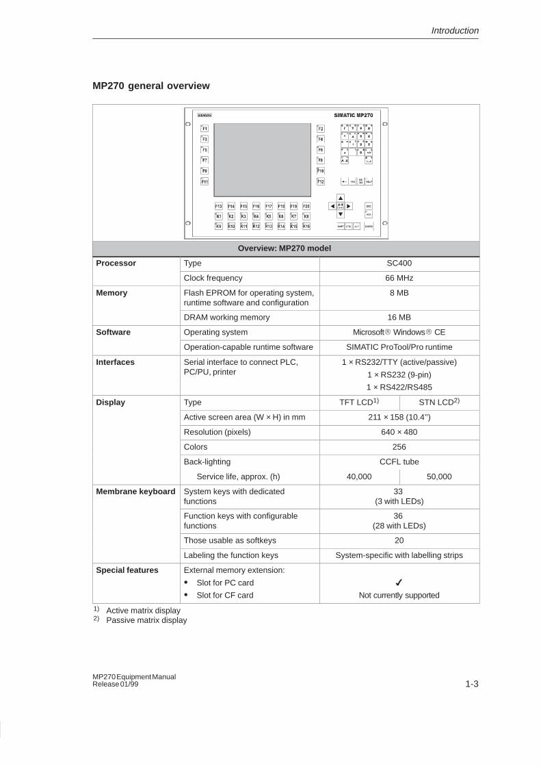
MP270 general overview
Overview: MP270 model
Processor Type SC400
Clock frequency 66 MHz
Memory Flash EPROM for operating system,runtime software and configuration
8 MB
DRAM working memory 16 MB
Software Operating system Microsoft� Windows� CE
Operation-capable runtime software SIMATIC ProTool/Pro runtime
Interfaces Serial interface to connect PLC,PC/PU, printer
1 × RS232/TTY (active/passive)
1 × RS232 (9-pin)
1 × RS422/RS485
Display Type TFT LCD1) STN LCD2)
Active screen area (W × H) in mm 211 × 158 (10.4’’)
Resolution (pixels) 640 × 480
Colors 256
Back-lighting CCFL tube
Service life, approx. (h) 40,000 50,000
Membrane keyboard System keys with dedicatedfunctions
33 (3 with LEDs)
Function keys with configurablefunctions
36 (28 with LEDs)
Those usable as softkeys 20
Labeling the function keys System-specific with labelling strips
Special features External memory extension:
� Slot for PC card
� Slot for CF card
�
Not currently supported
1) Active matrix display2) Passive matrix display
Introduction
1-4MP270 Equipment Manual
Release 01/99
Further information
Detailed information on the technical data of the MP270 is provided in Appendix Aof this manual.
Information on the configuration of the MP270 is provided in the user’s guideProTool Configuring Windows-based Systems.
Connection of the MP270 to the PLC is described in the user’s guideCommunication for Windows-based Systems.
2-1MP270 Equipment ManualRelease 01/99
Functionality
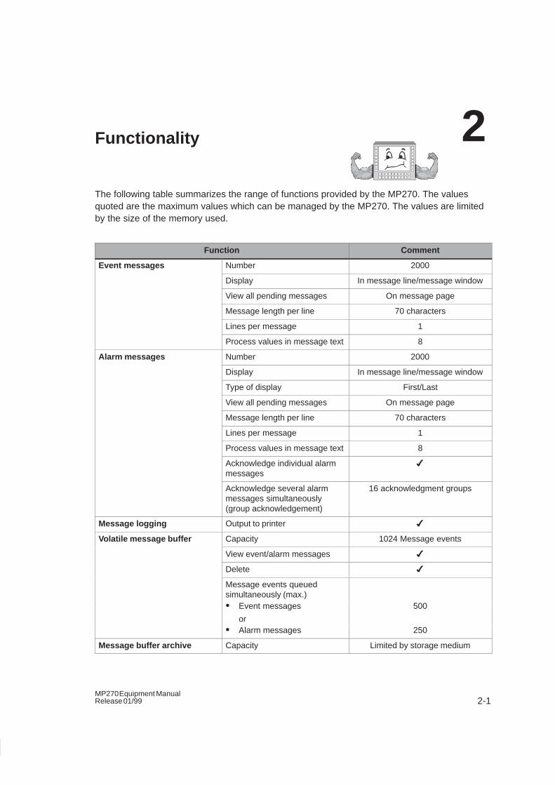
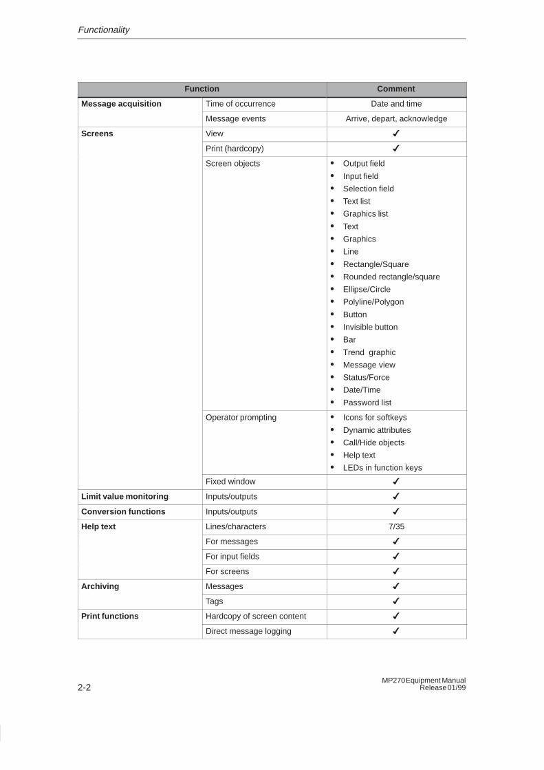
The following table summarizes the range of functions provided by the MP270. The valuesquoted are the maximum values which can be managed by the MP270. The values are limitedby the size of the memory used.
Function Comment
Event messages Number 2000
Display In message line/message window
View all pending messages On message page
Message length per line 70 characters
Lines per message 1
Process values in message text 8
Alarm messages Number 2000
Display In message line/message window
Type of display First/Last
View all pending messages On message page
Message length per line 70 characters
Lines per message 1
Process values in message text 8
Acknowledge individual alarmmessages
�
Acknowledge several alarmmessages simultaneously(group acknowledgement)
16 acknowledgment groups
Message logging Output to printer �
Volatile message buffer Capacity 1024 Message events
View event/alarm messages �
Delete �
Message events queuedsimultaneously (max.)� Event messages
or
500
� Alarm messages 250
Message buffer archive Capacity Limited by storage medium
2
Functionality
2-2MP270 Equipment Manual
Release 01/99
CommentFunction
Message acquisition Time of occurrence Date and time
Message events Arrive, depart, acknowledge
Screens View �
Print (hardcopy) �
Screen objects � Output field
� Input field
� Selection field
� Text list
� Graphics list
� Text
� Graphics
� Line
� Rectangle/Square
� Rounded rectangle/square
� Ellipse/Circle
� Polyline/Polygon
� Button
� Invisible button
� Bar
� Trend graphic
� Message view
� Status/Force
� Date/Time
� Password list
Operator prompting � Icons for softkeys
� Dynamic attributes
� Call/Hide objects
� Help text
� LEDs in function keys
Fixed window �
Limit value monitoring Inputs/outputs �
Conversion functions Inputs/outputs �
Help text Lines/characters 7/35
For messages �
For input fields �
For screens �
Archiving Messages �
Tags �
Print functions Hardcopy of screen content �
Direct message logging �
Functionality
2-3MP270 Equipment ManualRelease 01/99
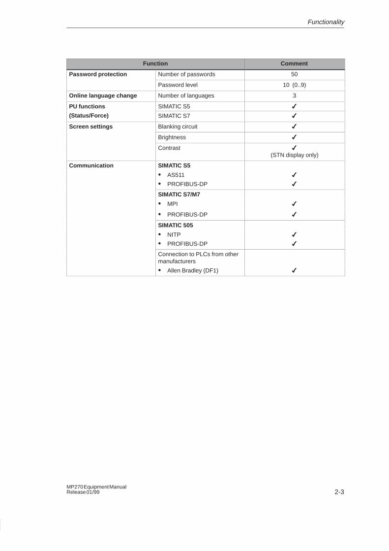
CommentFunction
Password protection Number of passwords 50
Password level 10 (0..9)
Online language change Number of languages 3
PU functions SIMATIC S5 �
(Status/Force) SIMATIC S7 �
Screen settings Blanking circuit �
Brightness �
Contrast �
(STN display only)
Communication SIMATIC S5
� AS511
� PROFIBUS-DP
�
�
SIMATIC S7/M7
� MPI �
� PROFIBUS-DP �
SIMATIC 505
� NITP
� PROFIBUS-DP
�
�
Connection to PLCs from othermanufacturers
� Allen Bradley (DF1) �

Functionality
2-4MP270 Equipment Manual
Release 01/99
3-1MP270 Equipment ManualRelease 01/99
Commissioning
Flowchart
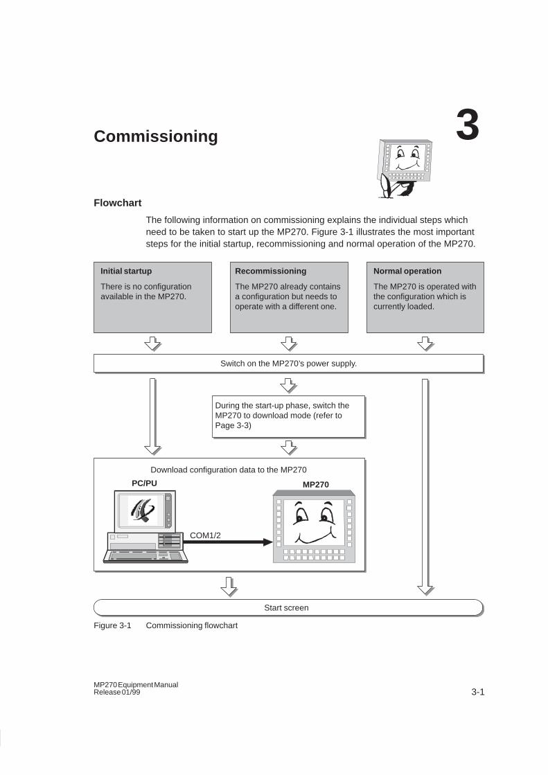
The following information on commissioning explains the individual steps whichneed to be taken to start up the MP270. Figure 3-1 illustrates the most importantsteps for the initial startup, recommissioning and normal operation of the MP270.
Download configuration data to the MP270
COM1/2
During the start-up phase, switch theMP270 to download mode (refer toPage 3-3)
Switch on the MP270’s power supply.
Initial startup
There is no configurationavailable in the MP270.
Recommissioning
The MP270 already containsa configuration but needs tooperate with a different one.
Normal operation
The MP270 is operated withthe configuration which iscurrently loaded.
Start screen
PC/PU MP270
Figure 3-1 Commissioning flowchart
3
Commissioning
3-2MP270 Equipment Manual
Release 01/99
Error diagnostics
An error which occurrs during commissioning or operation is normally displayed onthe MP270 by means of a system message.
Appendix C of this manual contains a list of some of the most important systemmessages and explanations on how to eliminate the causes.
3.1 Initial Startup
Action
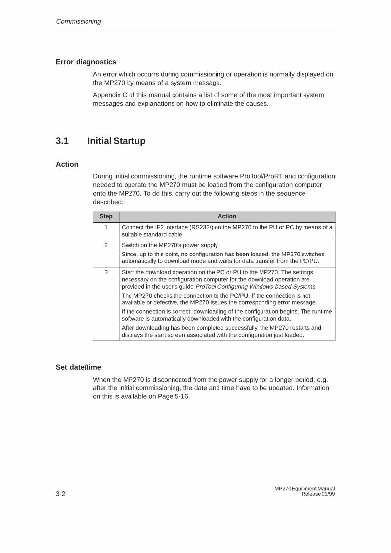
During initial commissioning, the runtime software ProTool/ProRT and configurationneeded to operate the MP270 must be loaded from the configuration computeronto the MP270. To do this, carry out the following steps in the sequencedescribed:
Step Action
1 Connect the IF2 interface (RS232/) on the MP270 to the PU or PC by means of asuitable standard cable.
2 Switch on the MP270’s power supply.
Since, up to this point, no configuration has been loaded, the MP270 switchesautomatically to download mode and waits for data transfer from the PC/PU.
3 Start the download operation on the PC or PU to the MP270. The settingsnecessary on the configuration computer for the download operation areprovided in the user’s guide ProTool Configuring Windows-based Systems.
The MP270 checks the connection to the PC/PU. If the connection is notavailable or defective, the MP270 issues the corresponding error message.
If the connection is correct, downloading of the configuration begins. The runtimesoftware is automatically downloaded with the configuration data.
After downloading has been completed successfully, the MP270 restarts anddisplays the start screen associated with the configuration just loaded.
Set date/time
When the MP270 is disconnected from the power supply for a longer period, e.g.after the initial commissioning, the date and time have to be updated. Informationon this is available on Page 5-16.
Commissioning
3-3MP270 Equipment ManualRelease 01/99
3.2 Recommissioning
Purpose
During recommissioning, the configuration and/or runtime software alreadyinstalled on the MP270 is replaced by means of serially downloading another. Inthis case, the configuration/runtime software is downloaded from the PC/PU to theMP270 via an RS232 connection.
There are two ways of setting the MP270 to download mode:
� During the start-up phase of the MP270
� Duriing normal operation
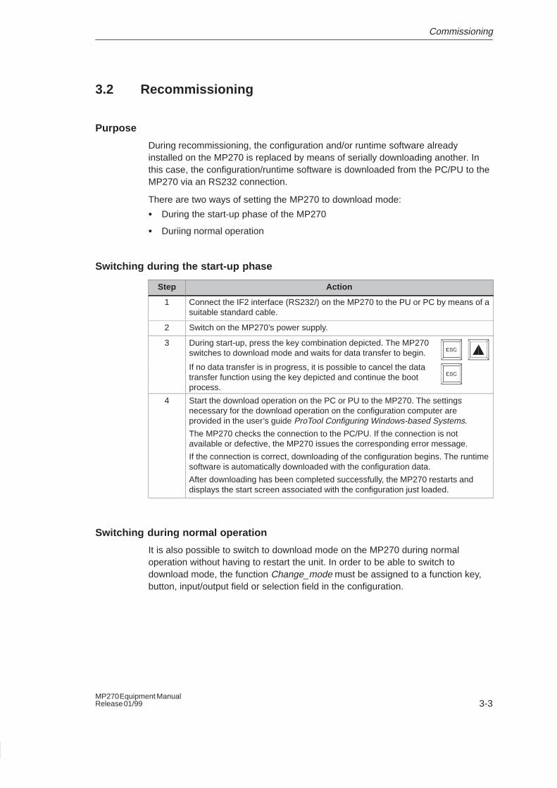
Switching during the start-up phase
Step Action
1 Connect the IF2 interface (RS232/) on the MP270 to the PU or PC by means of asuitable standard cable.
2 Switch on the MP270’s power supply.
3 During start-up, press the key combination depicted. The MP270switches to download mode and waits for data transfer to begin.
If no data transfer is in progress, it is possible to cancel the datatransfer function using the key depicted and continue the bootprocess.
4 Start the download operation on the PC or PU to the MP270. The settingsnecessary for the download operation on the configuration computer areprovided in the user’s guide ProTool Configuring Windows-based Systems.
The MP270 checks the connection to the PC/PU. If the connection is notavailable or defective, the MP270 issues the corresponding error message.
If the connection is correct, downloading of the configuration begins. The runtimesoftware is automatically downloaded with the configuration data.
After downloading has been completed successfully, the MP270 restarts anddisplays the start screen associated with the configuration just loaded.
Switching during normal operation
It is also possible to switch to download mode on the MP270 during normaloperation without having to restart the unit. In order to be able to switch todownload mode, the function Change_mode must be assigned to a function key,button, input/output field or selection field in the configuration.
Commissioning
3-4MP270 Equipment Manual
Release 01/99
3.3 Test Configuration
Simulation on a configuration computer
A simulator is supplied with the ProTool configuration software which enables theconfiguration to be tested on the PC/PU. A condition for this is that ProTool/Pro RT(Runtime) is installed on the configuration computer. The runtime software iscontained on the configuration software ProTool/Pro CS (Configuration System)installation CD.
The simulator is an individual application. It simulates the configuration offline, i.e.there is no connection to the PLC. Detailed information on the operation of thesimulator is provided in the user’s guide ProTool Configuring Windows-basedSystems.
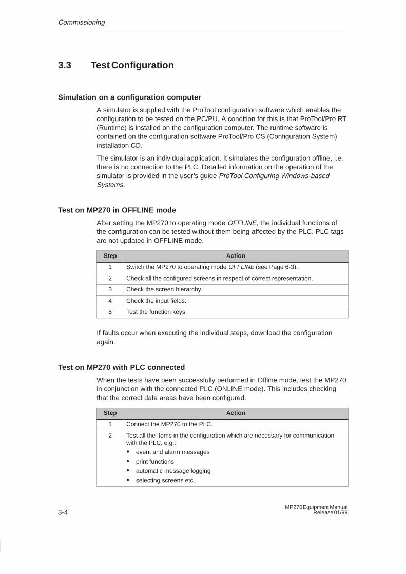
Test on MP270 in OFFLINE mode
After setting the MP270 to operating mode OFFLINE, the individual functions ofthe configuration can be tested without them being affected by the PLC. PLC tagsare not updated in OFFLINE mode.
Step Action
1 Switch the MP270 to operating mode OFFLINE (see Page 6-3).
2 Check all the configured screens in respect of correct representation.
3 Check the screen hierarchy.
4 Check the input fields.
5 Test the function keys.
If faults occur when executing the individual steps, download the configurationagain.
Test on MP270 with PLC connected
When the tests have been successfully performed in Offline mode, test the MP270in conjunction with the connected PLC (ONLINE mode). This includes checkingthat the correct data areas have been configured.
Step Action
1 Connect the MP270 to the PLC.
2 Test all the items in the configuration which are necessary for communicationwith the PLC, e.g.:
� event and alarm messages
� print functions
� automatic message logging
� selecting screens etc.
4-1MP270 Equipment ManualRelease 01/99
MP270 Operation
Operating concept
The operating status of the machine or system to be monitored can be observed inthe MP270 screen and the running process directly influenced by using thekeyboard.
This chapter provides information on the general operating procedures for theMP270. Information regarding operation for special screen objects is provided inChapter 5.
4.1 Integrated Keyboard
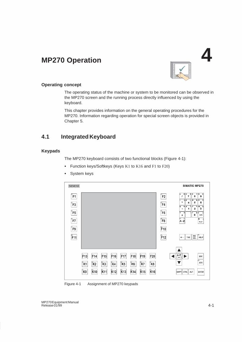
Keypads
The MP270 keyboard consists of two functional blocks (Figure 4-1):
� Function keys/Softkeys (Keys K1 to K16 and F1 to F20)
� System keys
Figure 4-1 Assignment of MP270 keypads
4
MP270 Operation
4-2MP270 Equipment Manual
Release 01/99
Function keys for global function assignment
A function key for global function assignment always triggers the same action onthe MP270 or in the PLC regardless of the screen currently open (globalsignificance on the MP270). These actions could include:
� Open screen
� Display current alarm messages
� Print screen (hardcopy)
The following function keys can be assigned during configuration:
...
...
Function keys for local function assignment (softkeys)
A function key for local function assignment (softkey) can trigger different actionson the MP270 or in the PLC according to the screen currently open (localsignificance of current screen). The function of a softkey is normally indicated byan icon located at the edge of the current screen.
All the function keys located directly at the edge of the screen can be assignedlocally significant functions during configuration. This concerns the following keysin the case of the MP270:
...
Note
If you press a function key after you have changed screens, the function istriggered on the new screen before the screen is built.
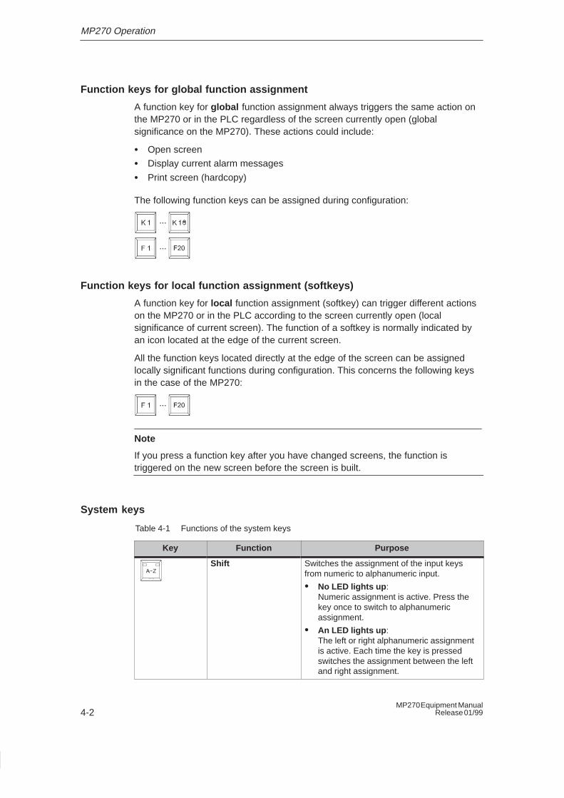
System keys
Table 4-1 Functions of the system keys
Key Function Purpose
Shift Switches the assignment of the input keysfrom numeric to alphanumeric input.
� No LED lights up :Numeric assignment is active. Press thekey once to switch to alphanumericassignment.
� An LED lights up :The left or right alphanumeric assignmentis active. Each time the key is pressedswitches the assignment between the leftand right assignment.
MP270 Operation
4-3MP270 Equipment ManualRelease 01/99
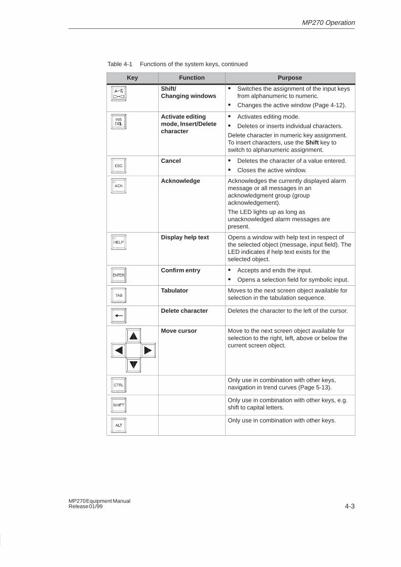
Table 4-1 Functions of the system keys, continued
PurposeFunctionKey
Shift/ Changing windows
� Switches the assignment of the input keysfrom alphanumeric to numeric.
� Changes the active window (Page 4-12).
Activate editingmode, Insert/Deletecharacter
� Activates editing mode.
� Deletes or inserts individual characters.
Delete character in numeric key assignment.To insert characters, use the Shift key toswitch to alphanumeric assignment.
Cancel � Deletes the character of a value entered.
� Closes the active window.
Acknowledge Acknowledges the currently displayed alarmmessage or all messages in anacknowledgment group (groupacknowledgement).
The LED lights up as long asunacknowledged alarm messages arepresent.
Display help text Opens a window with help text in respect ofthe selected object (message, input field). TheLED indicates if help text exists for theselected object.
Confirm entry � Accepts and ends the input.
� Opens a selection field for symbolic input.
Tabulator Moves to the next screen object available forselection in the tabulation sequence.
Delete character Deletes the character to the left of the cursor.
Move cursor Move to the next screen object available forselection to the right, left, above or below thecurrent screen object.
Only use in combination with other keys,navigation in trend curves (Page 5-13).
Only use in combination with other keys, e.g.shift to capital letters.
Only use in combination with other keys.
MP270 Operation
4-4MP270 Equipment Manual
Release 01/99
Key combinations
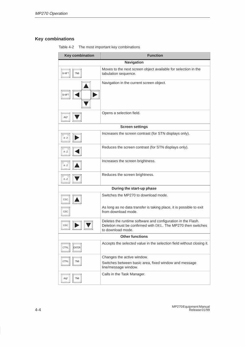
Table 4-2 The most important key combinations
Key combination Function
Navigation
Moves to the next screen object available for selection in thetabulation sequence.
Navigation in the current screen object.
Opens a selection field.
Screen settings
Increases the screen contrast (for STN displays only).
Reduces the screen contrast (for STN displays only).
Increases the screen brightness.
Reduces the screen brightness.
During the start-up phase
Switches the MP270 to download mode.
As long as no data transfer is taking place, it is possible to exitfrom download mode.
Deletes the runtime software and configuration in the Flash.Deletion must be confirmed with DEL. The MP270 then switchesto download mode.
Other functions
Accepts the selected value in the selection field without closing it.
Changes the active window.
Switches between basic area, fixed window and messageline/message window.
Calls in the Task Manager.
MP270 Operation
4-5MP270 Equipment ManualRelease 01/99
4.2 Entering Values
Marking
On selecting an input field, the entire field content is marked by changing color.After pressing a key (except a cursor key), the field content is deleted and the newinput displayed.
Press a cursor key after selecting the field and the field marking changes back; thecursor can be moved freely within the field.
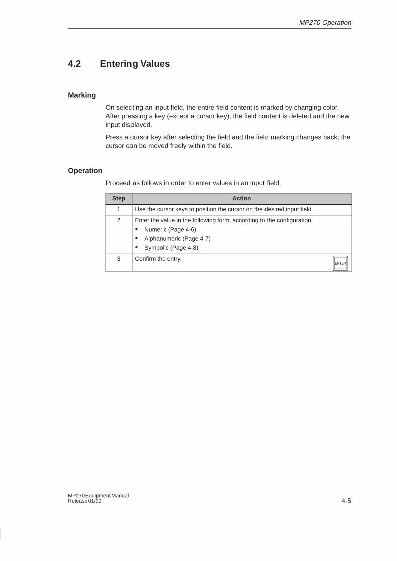
Operation
Proceed as follows in order to enter values in an input field:
Step Action
1 Use the cursor keys to position the cursor on the desired input field.
2 Enter the value in the following form, according to the configuration:
� Numeric (Page 4-6)
� Alphanumeric (Page 4-7)
� Symbolic (Page 4-8)
3 Confirm the entry.
MP270 Operation
4-6MP270 Equipment Manual
Release 01/99
4.2.1 Enter numeric values
Action
Numeric values are entered character by character using the input keys on thesystem keyboard. If a value already exists in the field, this is deleted on enteringthe first character. After beginning entering a value, it is impossible to exit from thefield without either confirming the entry or canceling.
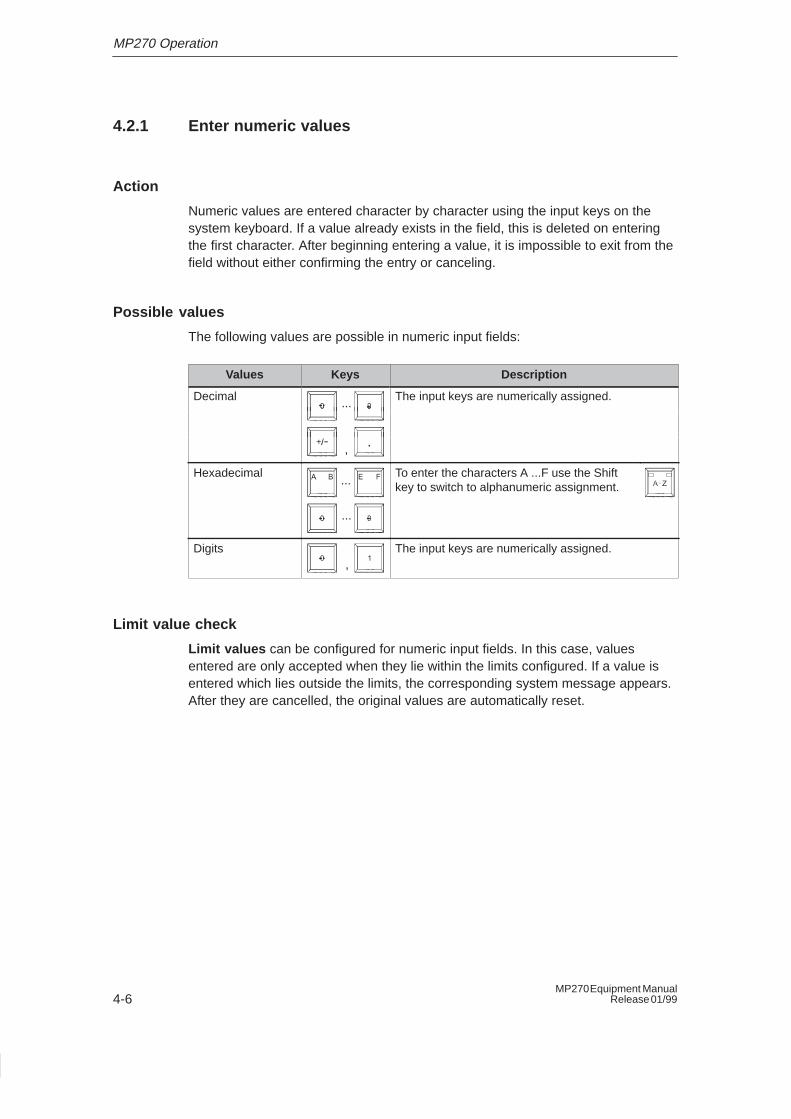
Possible values
The following values are possible in numeric input fields:
Values Keys Description
Decimal...
The input keys are numerically assigned....
,
Hexadecimal...
...
To enter the characters A ...F use the Shiftkey to switch to alphanumeric assignment.
Digits,
The input keys are numerically assigned.
Limit value check
Limit values can be configured for numeric input fields. In this case, valuesentered are only accepted when they lie within the limits configured. If a value isentered which lies outside the limits, the corresponding system message appears.After they are cancelled, the original values are automatically reset.
MP270 Operation
4-7MP270 Equipment ManualRelease 01/99
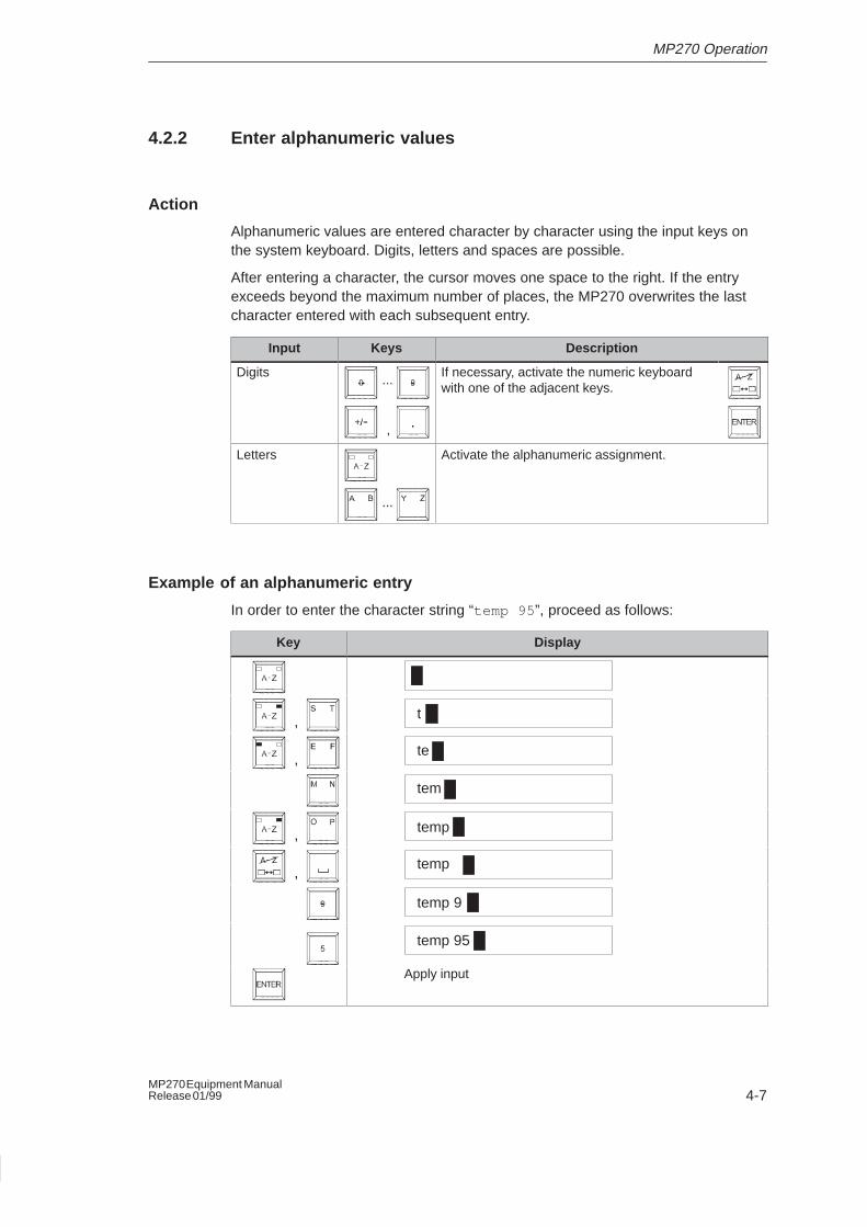
4.2.2 Enter alphanumeric values
Action
Alphanumeric values are entered character by character using the input keys onthe system keyboard. Digits, letters and spaces are possible.
After entering a character, the cursor moves one space to the right. If the entryexceeds beyond the maximum number of places, the MP270 overwrites the lastcharacter entered with each subsequent entry.
Input Keys Description
Digits...
,
If necessary, activate the numeric keyboardwith one of the adjacent keys.
Letters
...
Activate the alphanumeric assignment.
Example of an alphanumeric entry
In order to enter the character string “temp 95 ”, proceed as follows:
Key Display
, t
,te
tem
, temp
,temp
temp 9
temp 95
Apply input
MP270 Operation
4-8MP270 Equipment Manual
Release 01/99
4.2.3 Enter symbolic values
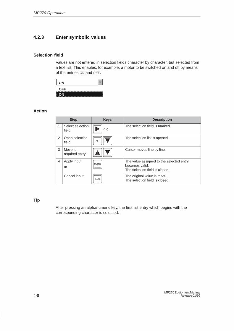
Selection field
Values are not entered in selection fields character by character, but selected froma text list. This enables, for example, a motor to be switched on and off by meansof the entries ON and OFF.
ON
ON
OFF
Action
Step Keys Description
1 Select selectionfield e.g.
The selection field is marked.
2 Open selectionfield
The selection list is opened.
3 Move torequired entry
Cursor moves line by line.
4 Apply input
or
The value assigned to the selected entrybecomes valid.The selection field is closed.
Cancel input The original value is reset.The selection field is closed.
Tip
After pressing an alphanumeric key, the first list entry which begins with thecorresponding character is selected.
MP270 Operation
4-9MP270 Equipment ManualRelease 01/99
4.3 Call Help Text
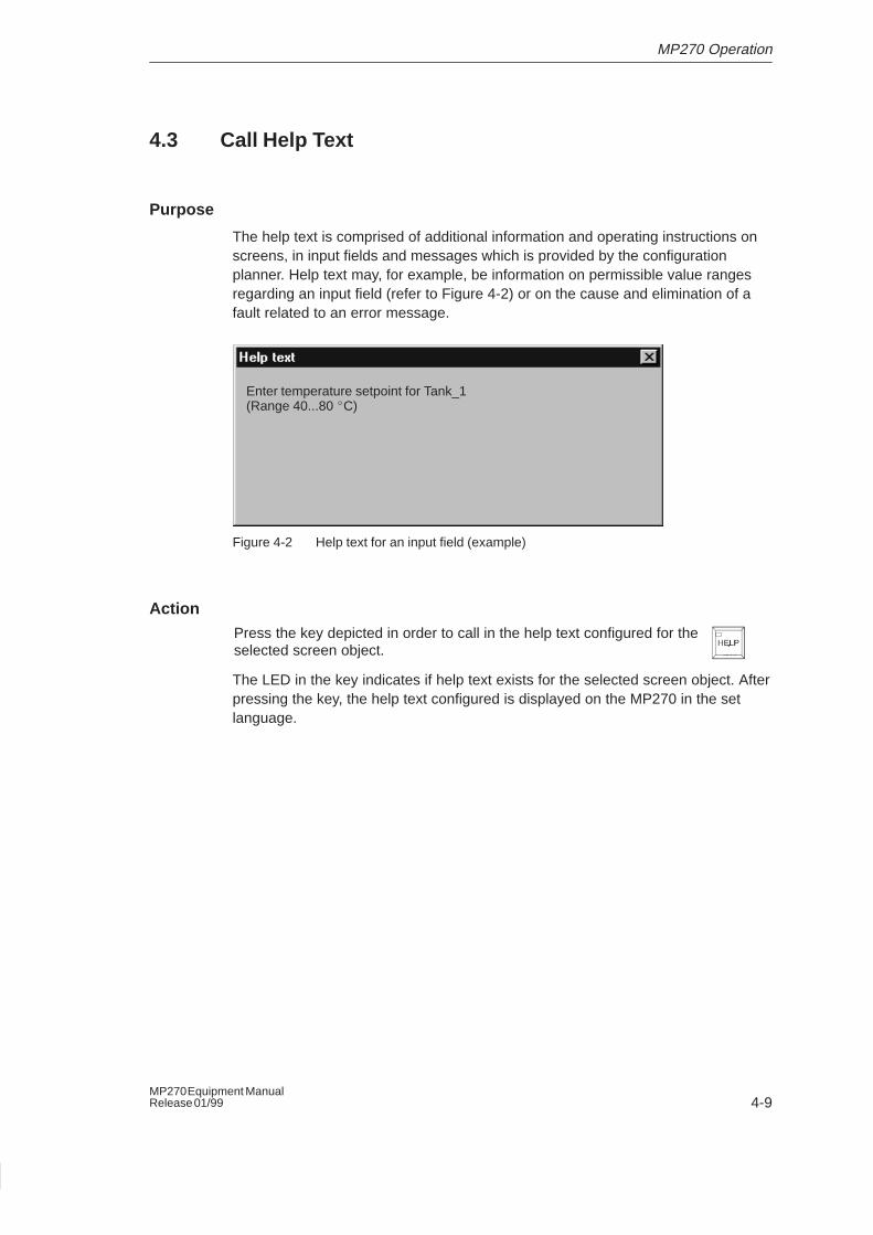
Purpose
The help text is comprised of additional information and operating instructions onscreens, in input fields and messages which is provided by the configurationplanner. Help text may, for example, be information on permissible value rangesregarding an input field (refer to Figure 4-2) or on the cause and elimination of afault related to an error message.
Enter temperature setpoint for Tank_1(Range 40...80 �C)
Figure 4-2 Help text for an input field (example)
ActionPress the key depicted in order to call in the help text configured for theselected screen object.
The LED in the key indicates if help text exists for the selected screen object. Afterpressing the key, the help text configured is displayed on the MP270 in the setlanguage.
MP270 Operation
4-10MP270 Equipment Manual
Release 01/99
4.4 Operating Screens
What is a screen?
Screens visualize the progress of processes and display specified process values.A screen contains logically related process data which the MP270 can both displayand modify by operating the individual values.
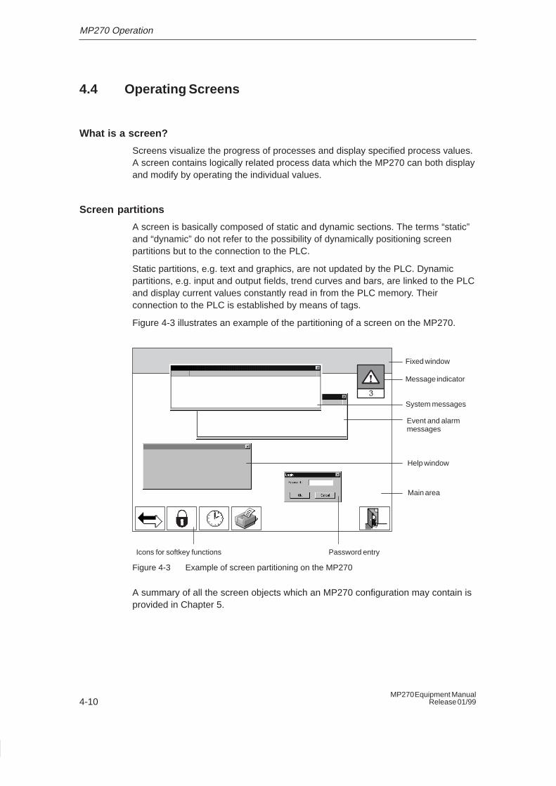
Screen partitions
A screen is basically composed of static and dynamic sections. The terms “static”and “dynamic” do not refer to the possibility of dynamically positioning screenpartitions but to the connection to the PLC.
Static partitions, e.g. text and graphics, are not updated by the PLC. Dynamicpartitions, e.g. input and output fields, trend curves and bars, are linked to the PLCand display current values constantly read in from the PLC memory. Theirconnection to the PLC is established by means of tags.
Figure 4-3 illustrates an example of the partitioning of a screen on the MP270.
System messages
Event and alarmmessages
Main area
Fixed window
Icons for softkey functions
Message indicator
Help window
Password entry
Figure 4-3 Example of screen partitioning on the MP270
A summary of all the screen objects which an MP270 configuration may contain isprovided in Chapter 5.
MP270 Operation
4-11MP270 Equipment ManualRelease 01/99
Fixed window
The fixed window is an area at the top of the screen. The height of the fixedwindow can be configured. Since the content of the fixed window is independent ofthe screen currently displayed, it is especially suited for displaying importantprocess magnitudes or date and time.
Basic area
The basic area covers the entire screen. It is superimposed by all other areas(fixed window, message window, help window, etc.). The basic area contains thereal content of the screen currently open.
Icons
Icons are graphics of a fixed size located at the bottom and sides of the screen.They are defined during configuration and clearly indicate the functions of thesoftkeys in graphic form.
After pressing the respective softkey, F1 to F20, the function symbolized by theicon is activated either on the MP270 or in the PLC.
Message indicator
The message indicator is a graphical symbol which appears on thescreen when at least one alarm message is present on the MP270.
The indicator continues to blink as long as unacknowledged messagesare present.The number (in this case 3) represents the number of alarm messagespresent.
The message indicator is always displayed in the foreground.
MP270 Operation
4-12MP270 Equipment Manual
Release 01/99
Message window
System messagesThe MP270 displays internal operating statuses in the system message window.System messages indicate, for example, incorrect operations or communicationfaults. A summary of some of the most important system messages andexplanations on how to eliminate the causes are provided in Appendix C of thismanual.
Press the key depicted to close the system message window.
Event messages and alarm messagesThe MP270 uses the event and alarm message window to display operatingstatuses and faults concerning the machine or system connected to the PLC. Theposition of the window can be configured.
Since alarm messages indicate abnormal operating statuses, they mustbe acknowledged. Press the key depicted to acknowledge an alarmmessage.
Further information regarding the message window is provided on Page 5-7.
Help window
The help window displays specifically configured information concerning screens,input fields and messages (Figure 4-2, Page 4-9).
Changing active window
Several windows can be opened simultaneously when the MP270 isrunning in normal operation. In order to operate a window, use thekey combination depicted on the right to move between the followingwindows:
� Main area
� Fixed window
� Message line/Message window
Each time the combination is pressed, the cursor moves to the next window.
The window in which the cursor is located is the active window. Input/Operationsare possible in the active window. It is not possible to change to a window whichcontains no operable objects.
MP270 Operation
4-13MP270 Equipment ManualRelease 01/99
Select screen
Screens on the MP270can be viewed, edited and printed. The relevant screenmust have been selected beforehand. There are two ways in which to select ascreen:
� Function keyPressing a function key opens the corresponding screen defined in theconfiguration.
� Input fieldEnter the corresponding number of the screen to be viewed in the input field.
Screen saver
The brightness of the back-lighting for the screen is reduced with increasingoperational use for technological reasons. To increase the service life, the MP270automatically dims the screen if no key is pressed for a specified period of time.
The back-lighting becomes bright again after pressing any key. The functionassigned to that key is not triggered.

MP270 Operation
4-14MP270 Equipment Manual
Release 01/99
5-1MP270 Equipment ManualRelease 01/99
Operating Special Screen Objects
In this chapter
This chapter describes the various screen objects which can be contained in aMP270 configuration and explains how to operate special screen objects.
5.1 Overview of Screen Objects
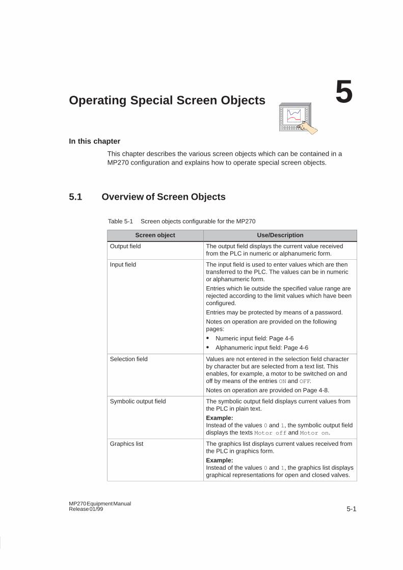
Table 5-1 Screen objects configurable for the MP270
Screen object Use/Description
Output field The output field displays the current value receivedfrom the PLC in numeric or alphanumeric form.
Input field The input field is used to enter values which are thentransferred to the PLC. The values can be in numericor alphanumeric form.
Entries which lie outside the specified value range arerejected according to the limit values which have beenconfigured.
Entries may be protected by means of a password.
Notes on operation are provided on the followingpages:
� Numeric input field: Page 4-6
� Alphanumeric input field: Page 4-6
Selection field Values are not entered in the selection field characterby character but are selected from a text list. Thisenables, for example, a motor to be switched on andoff by means of the entries ON and OFF.
Notes on operation are provided on Page 4-8.
Symbolic output field The symbolic output field displays current values fromthe PLC in plain text.
Example:Instead of the values 0 and 1, the symbolic output fielddisplays the texts Motor off and Motor on .
Graphics list The graphics list displays current values received fromthe PLC in graphics form.
Example:Instead of the values 0 and 1, the graphics list displaysgraphical representations for open and closed valves.
5
Operating Special Screen Objects
5-2MP270 Equipment Manual
Release 01/99
Table 5-1 Screen objects configurable for the MP270, continued
Use/DescriptionScreen object
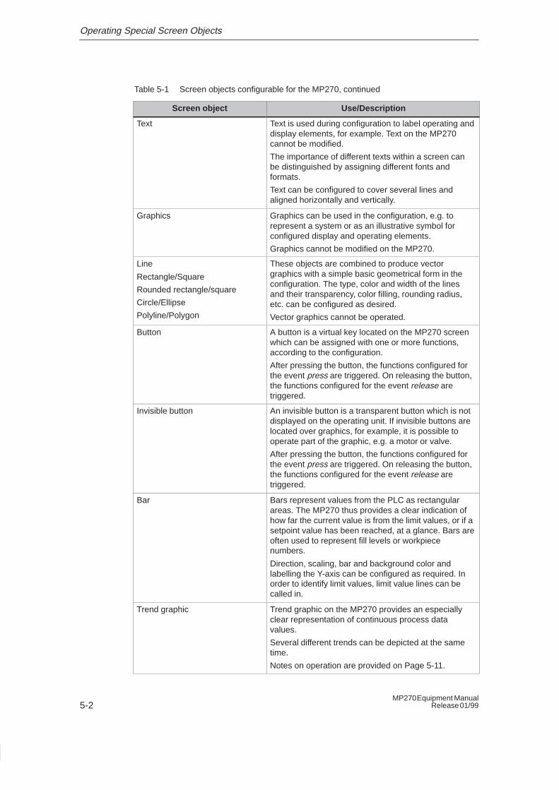
Text Text is used during configuration to label operating anddisplay elements, for example. Text on the MP270cannot be modified.
The importance of different texts within a screen canbe distinguished by assigning different fonts andformats.
Text can be configured to cover several lines andaligned horizontally and vertically.
Graphics Graphics can be used in the configuration, e.g. torepresent a system or as an illustrative symbol forconfigured display and operating elements.
Graphics cannot be modified on the MP270.
Line
Rectangle/Square
Rounded rectangle/square
Circle/Ellipse
Polyline/Polygon
These objects are combined to produce vectorgraphics with a simple basic geometrical form in theconfiguration. The type, color and width of the linesand their transparency, color filling, rounding radius,etc. can be configured as desired.
Vector graphics cannot be operated.
Button A button is a virtual key located on the MP270 screenwhich can be assigned with one or more functions,according to the configuration.
After pressing the button, the functions configured forthe event press are triggered. On releasing the button,the functions configured for the event release aretriggered.
Invisible button An invisible button is a transparent button which is notdisplayed on the operating unit. If invisible buttons arelocated over graphics, for example, it is possible tooperate part of the graphic, e.g. a motor or valve.
After pressing the button, the functions configured forthe event press are triggered. On releasing the button,the functions configured for the event release aretriggered.
Bar Bars represent values from the PLC as rectangularareas. The MP270 thus provides a clear indication ofhow far the current value is from the limit values, or if asetpoint value has been reached, at a glance. Bars areoften used to represent fill levels or workpiecenumbers.
Direction, scaling, bar and background color andlabelling the Y-axis can be configured as required. Inorder to identify limit values, limit value lines can becalled in.
Trend graphic Trend graphic on the MP270 provides an especiallyclear representation of continuous process datavalues.
Several different trends can be depicted at the sametime.
Notes on operation are provided on Page 5-11.
Operating Special Screen Objects
5-3MP270 Equipment ManualRelease 01/99
Table 5-1 Screen objects configurable for the MP270, continued
Use/DescriptionScreen object
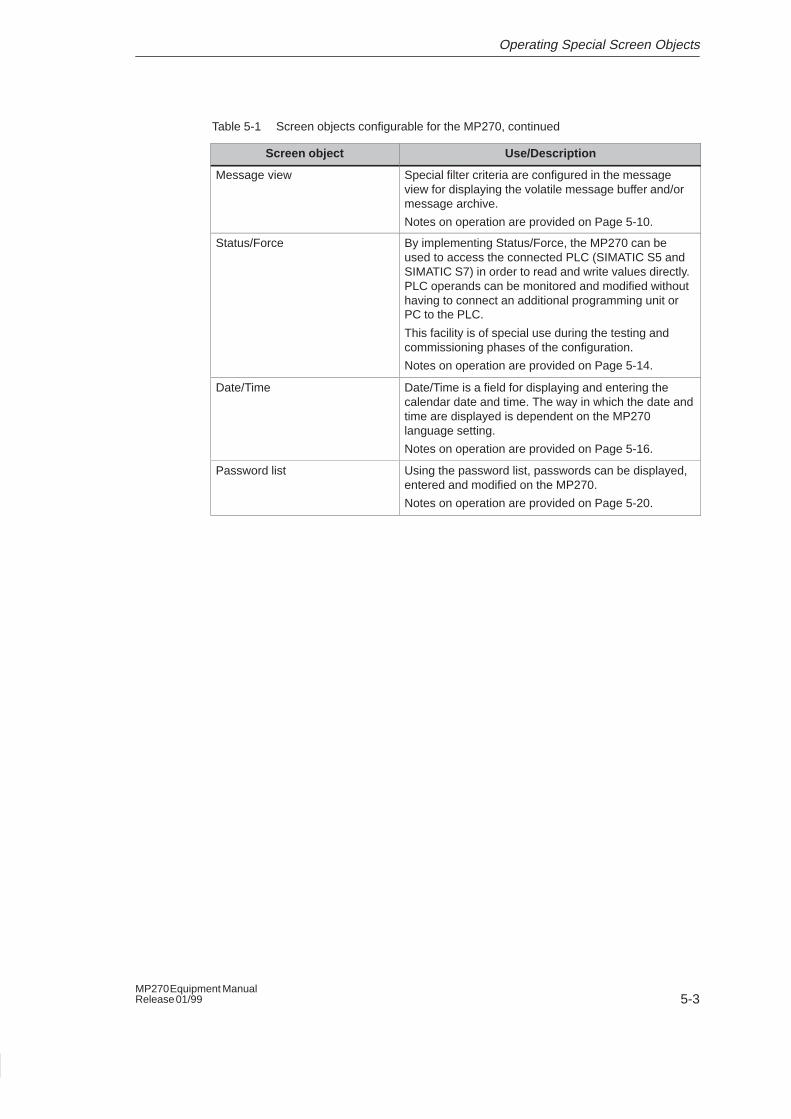
Message view Special filter criteria are configured in the messageview for displaying the volatile message buffer and/ormessage archive.
Notes on operation are provided on Page 5-10.
Status/Force By implementing Status/Force, the MP270 can beused to access the connected PLC (SIMATIC S5 andSIMATIC S7) in order to read and write values directly.PLC operands can be monitored and modified withouthaving to connect an additional programming unit orPC to the PLC.
This facility is of special use during the testing andcommissioning phases of the configuration.
Notes on operation are provided on Page 5-14.
Date/Time Date/Time is a field for displaying and entering thecalendar date and time. The way in which the date andtime are displayed is dependent on the MP270language setting.
Notes on operation are provided on Page 5-16.
Password list Using the password list, passwords can be displayed,entered and modified on the MP270.
Notes on operation are provided on Page 5-20.
Operating Special Screen Objects
5-4MP270 Equipment Manual
Release 01/99
5.2 Messages
Message categories
Messages on the MP270 indicate events and statuses related to controlprocesses. A message can contain text and tags. Parts of the text can beconfigured to flash or be underlined to distinguish it from other parts of the text.
The MP270 displays the following types of message:
� Event messages
indicate normal operating and process statuses and process progress, e.g.
– Motor on
– PLC in manual mode
– Operating temperature xx reached
� Alarm messagesindicate critical or dangerous operating or process statuses and require aresponse in the form of an acknowledgment.
Examples of alarm messages:
– Motor temperature too high
– Coolant empty
– Valve will not open
� System messagesindicate statuses and faults in the MP270 and PLC or communication betweenthem. They are triggered by the MP270 or PLC.
Examples of system messages are provided in Appendix C.
Message events
Messages are controlled by events and are triggered when a bit is set in the PLC.The MP270 establishes the following message events and assigns them a timestamp:
� Arrivedtime at which a message was triggered by the PLC or MP270.
� Departed
time at which a message was withdrawn by the PLC.
� Acknowledged (alarm messages only)
time at which an alarm message was acknowledged by the MP270 or PLC. Theacknowledgement confirms that the alarm message has been noted.
Operating Special Screen Objects
5-5MP270 Equipment ManualRelease 01/99
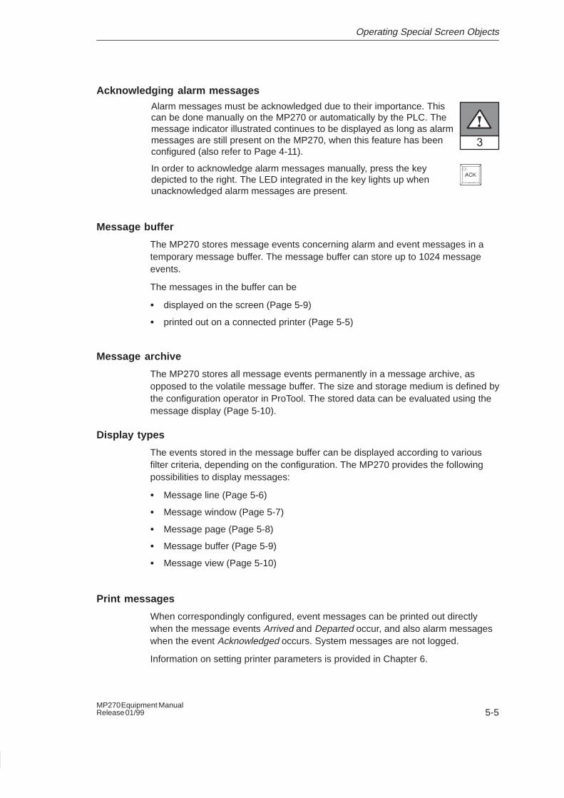
Acknowledging alarm messagesAlarm messages must be acknowledged due to their importance. Thiscan be done manually on the MP270 or automatically by the PLC. Themessage indicator illustrated continues to be displayed as long as alarmmessages are still present on the MP270, when this feature has beenconfigured (also refer to Page 4-11).
In order to acknowledge alarm messages manually, press the keydepicted to the right. The LED integrated in the key lights up whenunacknowledged alarm messages are present.
Message buffer
The MP270 stores message events concerning alarm and event messages in atemporary message buffer. The message buffer can store up to 1024 messageevents.
The messages in the buffer can be
� displayed on the screen (Page 5-9)
� printed out on a connected printer (Page 5-5)
Message archive
The MP270 stores all message events permanently in a message archive, asopposed to the volatile message buffer. The size and storage medium is defined bythe configuration operator in ProTool. The stored data can be evaluated using themessage display (Page 5-10).
Display types
The events stored in the message buffer can be displayed according to variousfilter criteria, depending on the configuration. The MP270 provides the followingpossibilities to display messages:
� Message line (Page 5-6)
� Message window (Page 5-7)
� Message page (Page 5-8)
� Message buffer (Page 5-9)
� Message view (Page 5-10)
Print messages
When correspondingly configured, event messages can be printed out directlywhen the message events Arrived and Departed occur, and also alarm messageswhen the event Acknowledged occurs. System messages are not logged.
Information on setting printer parameters is provided in Chapter 6.
Operating Special Screen Objects
5-6MP270 Equipment Manual
Release 01/99
Deleting messages
All message events concerning event and alarm messages are automaticallystored in the message buffer. There are two methods of deleting messages fromthe buffer:
� Automatic deletion on buffer overflowWhen the message buffer is no longer capable of accepting new messageevents, the MP270 automatically deletes a number of message events until theconfigured remaining buffer capacity is reached. In this case, the oldestmessages are deleted first.
� Deletion by operating the MP270
In order that messages can be deleted manually from the message buffer, thefunction Clear_message_buffer must be available in the configuration. In thisway, the following message categories can be selected for deletion according tothe configuration:
– All messages
– Alarm messages
– Event messages
– System messages
– S7 diagnostics messages
5.2.1 Message Line
Purpose
When a message line has been configured it is always displayed, regardless of thescreen selected. Only the latest message is displayed in the message line.
If display type line/line is configured, the message line displays an event or alarmmessage. In order to differentiate between them, alarm messages flash in thedisplay.
If display type window/line is configured, the message line displays an eventmessage. Alarm messages are displayed via a window which opens up.
Display priorities
Alarm messages always have priority over event messages. If no alarm messagesare present or they have all been acknowledged, event messages are displayed.
Operating Special Screen Objects
5-7MP270 Equipment ManualRelease 01/99
5.2.2 Message Window
Purpose
The message window displays all messages which are present which have no timestamp. It is possible to configure the sorting sequence displayed.
Alarm messages
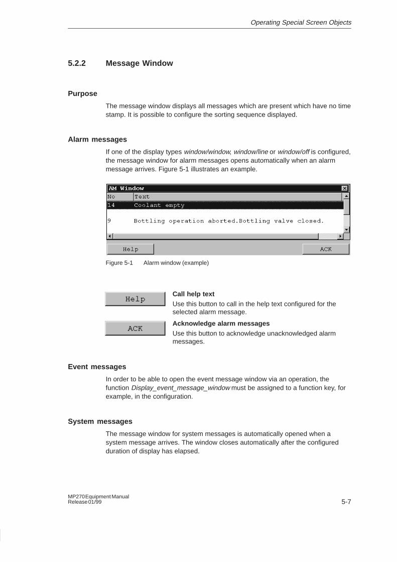
If one of the display types window/window, window/line or window/off is configured,the message window for alarm messages opens automatically when an alarmmessage arrives. Figure 5-1 illustrates an example.
Figure 5-1 Alarm window (example)
Call help text
Use this button to call in the help text configured for theselected alarm message.
Acknowledge alarm messages
Use this button to acknowledge unacknowledged alarmmessages.
Event messages
In order to be able to open the event message window via an operation, thefunction Display_event_message_window must be assigned to a function key, forexample, in the configuration.
System messages
The message window for system messages is automatically opened when asystem message arrives. The window closes automatically after the configuredduration of display has elapsed.
Operating Special Screen Objects
5-8MP270 Equipment Manual
Release 01/99
5.2.3 Message Page
Purpose
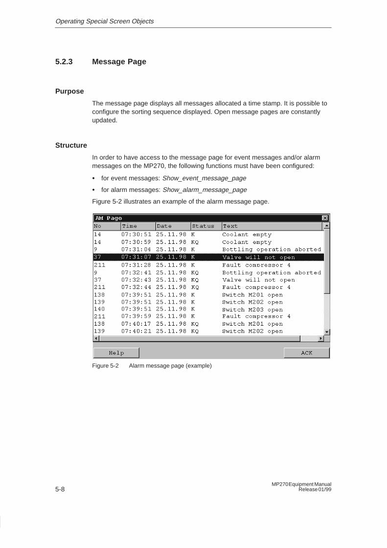
The message page displays all messages allocated a time stamp. It is possible toconfigure the sorting sequence displayed. Open message pages are constantlyupdated.
Structure
In order to have access to the message page for event messages and/or alarmmessages on the MP270, the following functions must have been configured:
� for event messages: Show_event_message_page
� for alarm messages: Show_alarm_message_page
Figure 5-2 illustrates an example of the alarm message page.
Figure 5-2 Alarm message page (example)
Operating Special Screen Objects
5-9MP270 Equipment ManualRelease 01/99
5.2.4 Message Buffer
Purpose
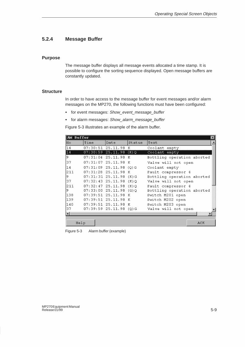
The message buffer displays all message events allocated a time stamp. It ispossible to configure the sorting sequence displayed. Open message buffers areconstantly updated.
Structure
In order to have access to the message buffer for event messages and/or alarmmessages on the MP270, the following functions must have been configured:
� for event messages: Show_event_message_buffer
� for alarm messages: Show_alarm_message_buffer
Figure 5-3 illustrates an example of the alarm buffer.
Figure 5-3 Alarm buffer (example)
Operating Special Screen Objects
5-10MP270 Equipment Manual
Release 01/99
5.2.5 Message View
Purpose
It is possible to define specific views of the message buffer (volatile or archive) inthe message view. Various filter criteria are provided in ProTool for this purpose.
The following can be configured
� Message archive
� Message categories
� Message events
� Number of columns
� Alarm message sorting
� Buttons
Structure
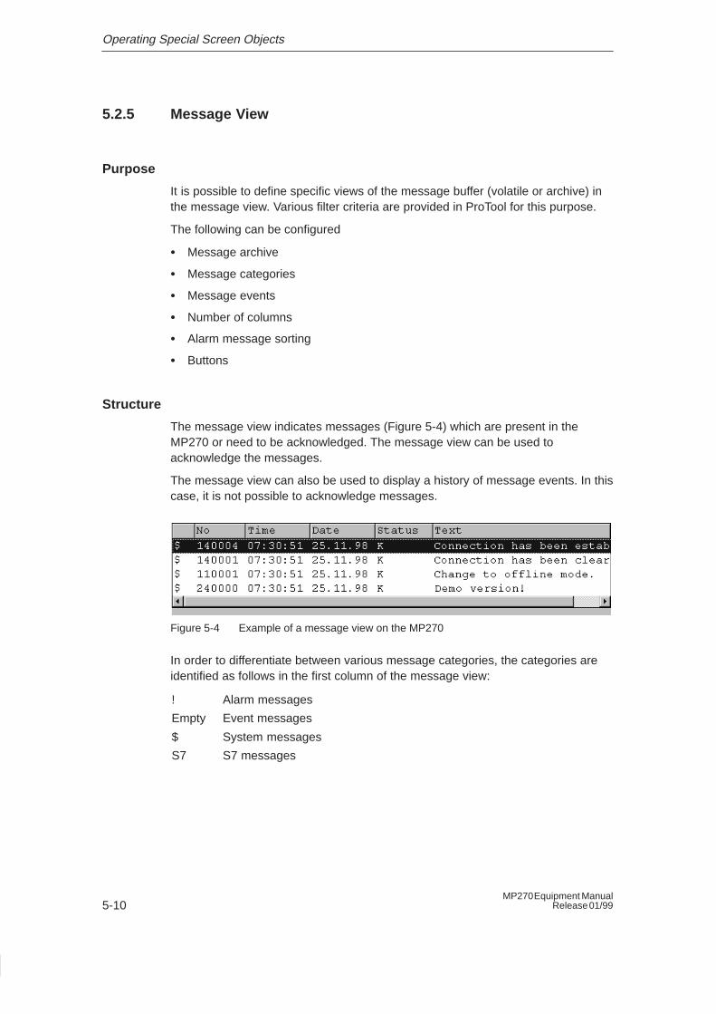
The message view indicates messages (Figure 5-4) which are present in theMP270 or need to be acknowledged. The message view can be used toacknowledge the messages.
The message view can also be used to display a history of message events. In thiscase, it is not possible to acknowledge messages.
Figure 5-4 Example of a message view on the MP270
In order to differentiate between various message categories, the categories areidentified as follows in the first column of the message view:
! Alarm messages
Empty Event messages
$ System messages
S7 S7 messages
Operating Special Screen Objects
5-11MP270 Equipment ManualRelease 01/99
5.3 Trend Graphics
Purpose
Trend graphics on the MP270 provide an especially clear visualization ofcontinuous process data values. In the case of processes which change veryslowly, it is possible to visualize trends of previous events, thus enabling estimationof future trends within a process. On the other hand, the output of data concerningprocesses which run extremely quickly enables large quantities of data to beevaluated by simple means.
Configurable properties
The MP270 can depict several different trends in the trend graphic at the sametime. The following properties are among those which can be configured for a trendgraphic:
� Representation
Different trends can appear in different colors, as lines, dots or bars.
� Types of trend
– Real-time trend
The MP270 reads just one trend value from the PLC per pulse or trigger andinserts it in the trend displayed.
– Pattern trend
By setting a trigger bit, the MP270 reads all the trend values from the PLCsimultaneously and displays them as a trend.
� Trigger
The type of trigger determines how the MP270 reads the trend data:
– Pulse triggeringThe MP270 reads the data from the PLC within a defined time matrix.
– Bit triggering
The MP270 reads the data, triggered by an event. The event is triggered bythe PLC through setting a defined bit.
� Limit values
The MP270 implements color changes to visually indicate that configured limitvalues have been reached or exceeded.
Operating Special Screen Objects
5-12MP270 Equipment Manual
Release 01/99
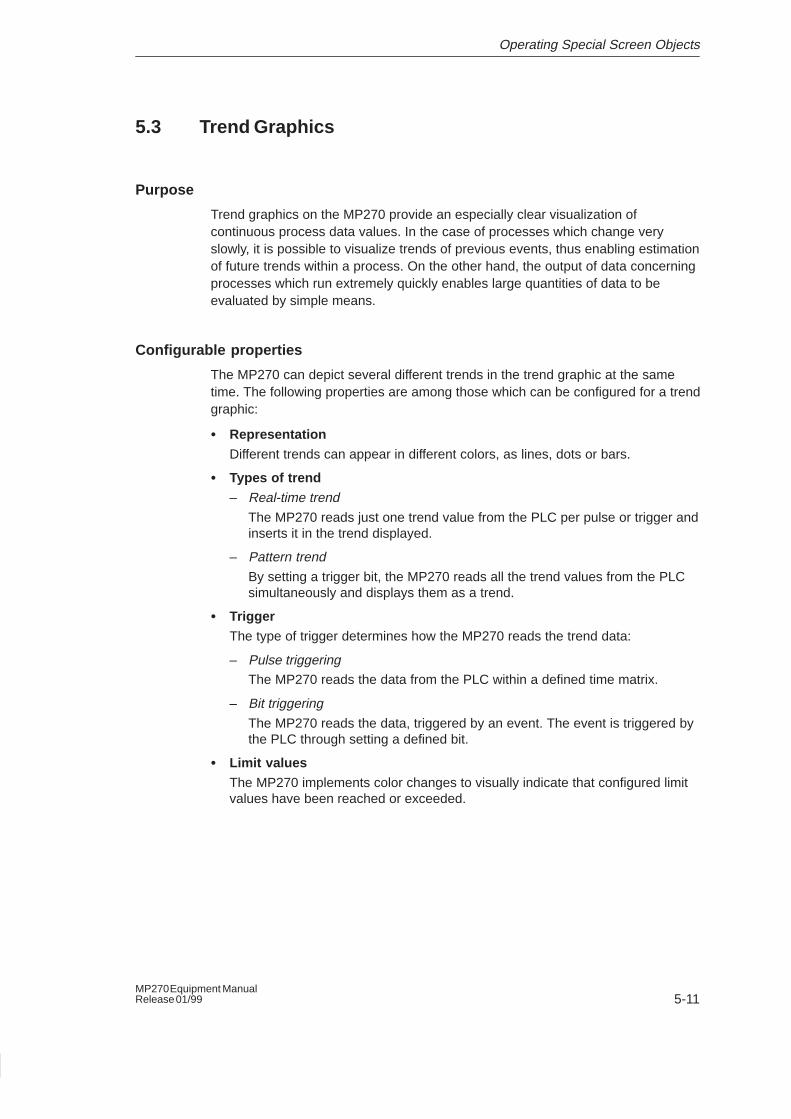
Structure
Figure 5-5 illustrates an example of a trend graphic with configured buttons tonavigate within the trend.
Figure 5-5 Operable trend (example)
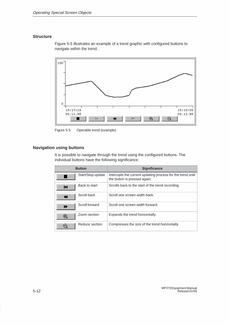
Navigation using buttons
It is possible to navigate through the trend using the configured buttons. Theindividual buttons have the following significance:
Button Significance
Start/Stop update Interrupts the current updating process for the trend untilthe button is pressed again.
Back to start Scrolls back to the start of the trend recording.
Scroll back Scroll one screen width back.
Scroll forward Scroll one screen width forward.
Zoom section Expands the trend horizontally.
Reduce section Compresses the size of the trend horizontally.
Operating Special Screen Objects
5-13MP270 Equipment ManualRelease 01/99
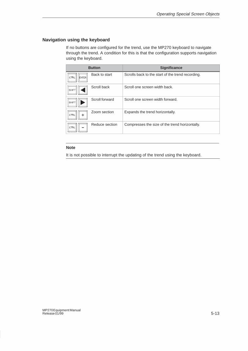
Navigation using the keyboard
If no buttons are configured for the trend, use the MP270 keyboard to navigatethrough the trend. A condition for this is that the configuration supports navigationusing the keyboard.
Button Significance
Back to start Scrolls back to the start of the trend recording.
Scroll back Scroll one screen width back.
Scroll forward Scroll one screen width forward.
Zoom section Expands the trend horizontally.
Reduce section Compresses the size of the trend horizontally.
Note
It is not possible to interrupt the updating of the trend using the keyboard.
Operating Special Screen Objects
5-14MP270 Equipment Manual
Release 01/99
5.4 Status/Force
Purpose
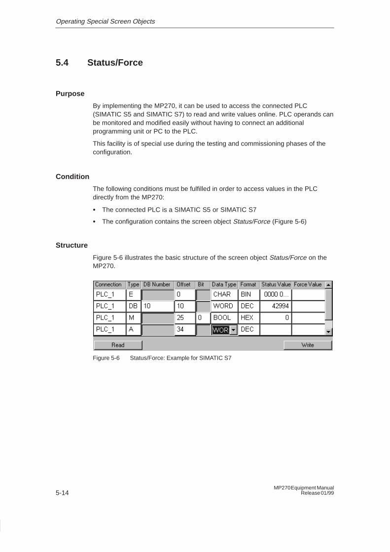
By implementing the MP270, it can be used to access the connected PLC(SIMATIC S5 and SIMATIC S7) to read and write values online. PLC operands canbe monitored and modified easily without having to connect an additionalprogramming unit or PC to the PLC.
This facility is of special use during the testing and commissioning phases of theconfiguration.
Condition
The following conditions must be fulfilled in order to access values in the PLCdirectly from the MP270:
� The connected PLC is a SIMATIC S5 or SIMATIC S7
� The configuration contains the screen object Status/Force (Figure 5-6)
Structure
Figure 5-6 illustrates the basic structure of the screen object Status/Force on theMP270.
Figure 5-6 Status/Force: Example for SIMATIC S7
Operating Special Screen Objects
5-15MP270 Equipment ManualRelease 01/99
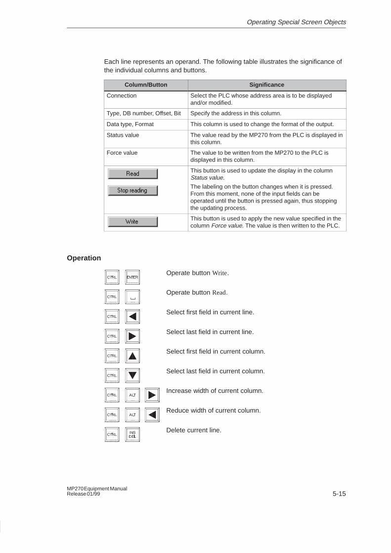
Each line represents an operand. The following table illustrates the significance ofthe individual columns and buttons.
Column/Button Significance
Connection Select the PLC whose address area is to be displayedand/or modified.
Type, DB number, Offset, Bit Specify the address in this column.
Data type, Format This column is used to change the format of the output.
Status value The value read by the MP270 from the PLC is displayed inthis column.
Force value The value to be written from the MP270 to the PLC isdisplayed in this column.
This button is used to update the display in the columnStatus value.
The labeling on the button changes when it is pressed.From this moment, none of the input fields can beoperated until the button is pressed again, thus stoppingthe updating process.
This button is used to apply the new value specified in thecolumn Force value. The value is then written to the PLC.
Operation
Operate button Write.
Operate button Read.
Select first field in current line.
Select last field in current line.
Select first field in current column.
Select last field in current column.
Increase width of current column.
Reduce width of current column.
Delete current line.
Operating Special Screen Objects
5-16MP270 Equipment Manual
Release 01/99
5.5 Date/Time
Purpose
The screen object Date/Time indicates the current values for the time and/or dateon the MP270. The time can be modified online if the corresponding feature isconfigured.
The calendar date and time values are synchronized with the system values in theoperating system. The MP270 accesses these values, for example, to assign timestamps to message events (Page 5-4).
Note
The MP270 only stores the system time for a few hours if the optional backupbattery is not installed (Chapter 9). If the unit is disconnected from the powersupply for a longer period, the date and time must be updated followingcommissioning.
Configurable properties
The following properties are amongst those which can be configured forDate/Time:
� Editing permittedThe option of modifying date and time on the MP270 online can be activatedand deactivated.
� Display time/Display dateIt is possible to display just the date or just the time.
� Date format (long/short)
The name of the day and month can be displayed in plain text or numerically.Table 5-2 illustrates some examples in various languages.
Note
If the Date is configured in the long format, the screen object “Date/Time” cannotbe operated.
Operating Special Screen Objects
5-17MP270 Equipment ManualRelease 01/99
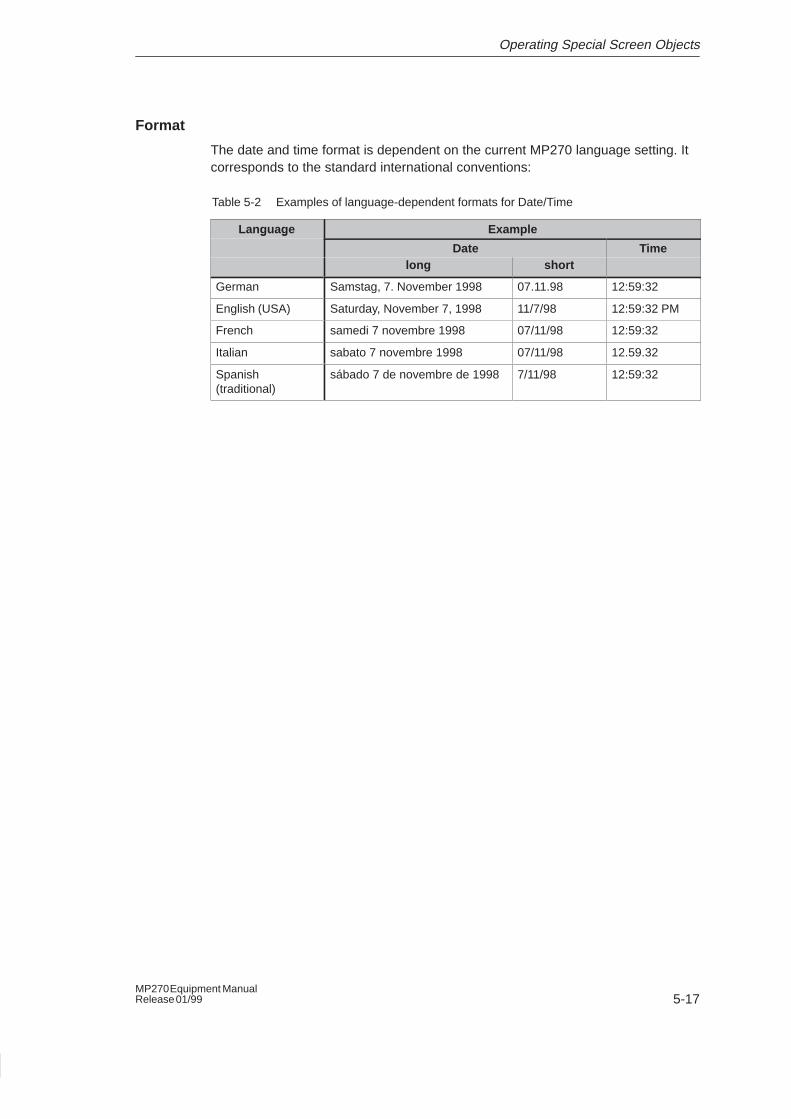
Format
The date and time format is dependent on the current MP270 language setting. Itcorresponds to the standard international conventions:
Table 5-2 Examples of language-dependent formats for Date/Time
Language Exampleg g
Date Timelong short
German Samstag, 7. November 1998 07.11.98 12:59:32
English (USA) Saturday, November 7, 1998 11/7/98 12:59:32 PM
French samedi 7 novembre 1998 07/11/98 12:59:32
Italian sabato 7 novembre 1998 07/11/98 12.59.32
Spanish(traditional)
sábado 7 de novembre de 1998 7/11/98 12:59:32
Operating Special Screen Objects
5-18MP270 Equipment Manual
Release 01/99
5.6 Password Protection
Purpose
During configuration using ProTool, operating elements, such as input fields,buttons and function keys, can be protected against unauthorized use by applyinga password. Important parameters and settings can then only be modified byauthorized personnel.
Password hierarchy
Hierarchically defined password levels 0 to 9 are provided for password protection.When a password is assigned to an individual user or to a whole user group, thepermission to execute functions at a specific level is assigned simultaneously. If anuser is assigned to password level 4, he only has the permission to executefunctions in password levels 0 to 4.
Password level
Password level 0 :
The functions assigned to this level, the lowest in the hierarchy, have little or noeffect on operations. They normally concern functions without any input options,such as displaying messages.
In order to trigger functions assigned to password level 0, no password needs tobe entered.
Password levels 1 to 8 :
Functions are assigned to levels 1 to 8 according to their increasing importance.Before triggering a function with a password level greater than 0 the MP270requests the corresponding password to be entered.
Password level 9 :
Only the superuser has the rights to execute functions assigned to password level9 (system administrator or service technician). The superuser has access to all theMP270 functions.
Operating Special Screen Objects
5-19MP270 Equipment ManualRelease 01/99
5.6.1 Logging in and out of the MP270
Login
After calling a password protected function, the MP270 automatically requests theentry of a password. It is not necessary to enter the password again to triggerfunctions in this or a lower level.
Logout
In order to rule out operation by unauthorized personnel, a password level greaterthan 0 should not remain active on the MP270 over too long a period of time. Thefollowing options are available to explicitly reset passwords levels:
� Configured logout time expires
If the MP270 is not used within the configured logout time (timeout), itautomatically resets the current password level to 0.
� Logout from MP270
If the configuration links the function Logoff_user with an operating element, theelement can be used to reset the current password level to 0 on the MP270.
Operating Special Screen Objects
5-20MP270 Equipment Manual
Release 01/99
5.6.2 Password management
Password list
Individual personnel can be entered in a password list on the MP270 and assigneda password level, according to their qualification and area of responsibility.
The password list contains all the passwords configured on the MP270. The list isstored in the MP270, safeguarded against power failure.
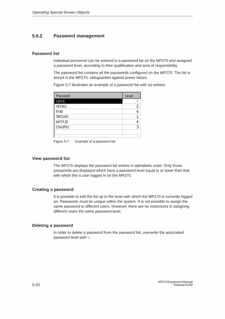
Figure 5-7 illustrates an example of a password list with six entries.
Figure 5-7 Example of a password list
View password list
The MP270 displays the password list entries in alphabetic order. Only thosepasswords are displayed which have a password level equal to or lower than thatwith which the is user logged in on the MP270.
Creating a password
It is possible to edit the list up to the level with which the MP270 is currently loggedon. Passwords must be unique within the system. It is not possible to assign thesame password to different users. However, there are no restrictions in assigningdifferent users the same password level.
Deleting a password
In order to delete a password from the password list, overwrite the associatedpassword level with 0.
6-1MP270 Equipment ManualRelease 01/99
System Settings
Overview
The general settings, listed below, can be modified online on the MP270:
� Language (Page 6-2)
� Operating mode (Page 6-3)
� Screen settings (Page 6-4)
� Settings on Windows�CE Control Panel (from Page 6-5)
– Printer
– Date/Time
– Format flash memory
6
System Settings
6-2MP270 Equipment Manual
Release 01/99
6.1 Set Language
Language-dependent objects
When downloading configurations from the configuration computer, up to threelanguages can be loaded on the MP270 at the same time. It is possible to switchbetween the languages, online, at any time and display language-dependentobjects (texts and formats) in other languages.
The following are language-dependent, for example
� Messages
� Screens
� Text lists
� Help texts
� Date/Time
Condition
In order to change languages on the MP270 while in operation, the functionLanguage must be assigned to a function key or selection field in the configuration.
Change language
Immediately after activating the function, all the language dependent objects aredisplayed in the new language.
Two different types of language change can be configured:
1. Each time the function is activated, the MP270 switches one language further,cyclically.
2. After activating the function, the language can be explicitly selected.
System Settings
6-3MP270 Equipment ManualRelease 01/99
6.2 Setting an Operating Mode
Operating modes
It is possible to switch between the two operating modes “Online” and “Offline” onthe MP270.
Offline modeThere is no logical connection between the MP270 and PLC. The MP270 can beoperated, but processes cannot be operated or visualized.
Online modeWhen using this mode, processes can be operated and visualized withoutrestriction. There is a logical connection between the MP270 and PLC or theMP270 attempts to establish one.
Download modeInformation on switching the MP270 to operating mode “Download mode” isprovided on Page 3-3.
Conditions for changing operating modes
In order to be able to switch between “Online” and “Offline”, the functionChange_mode must be assigned to a selection field, for example, in theconfiguration.
System Settings
6-4MP270 Equipment Manual
Release 01/99
6.3 Screen Settings
Purpose
In order to be able to view the MP270 screen well, even with changing lightingconditions, the brightness can be adjusted during operation and, when using unitswith an STN display, the screen contrast can also be adjusted.
Set brightness
The screen brightness can be adjusted by means of the following keycombinations:
Increases the brightness.
Reduces the brightness.
Set contrast
The screen contrast can be adjusted by means of the following key combinations:
Increases the contrast.
Reduces the contrast.
Note
In the case of units with TFT displays, the screen contrast is fixed.
Save settings
The MP270 saves the current settings, which are backed up should a power failureoccur, and sets them automatically when the unit is switched on again.
System Settings
6-5MP270 Equipment ManualRelease 01/99
6.4 Control Panel Settings
The Windows �CE Control Panel
The following settings can be defined for the system using the Windows�CEControl Panel:
� Set printer
� Set date/time
� Format flash memory
Opening and closing the Control Panel
In order to open the Control Panel, the function System Settings must be linked toan operating element in the configuration.
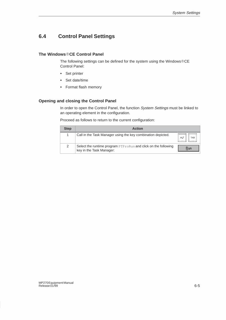
Proceed as follows to return to the current configuration:
Step Action
1 Call in the Task Manager using the key combination depicted.
2 Select the runtime program PTProRun and click on the followingkey in the Task Manager:
System Settings
6-6MP270 Equipment Manual
Release 01/99
Set printer
A printer can be selected and set up at this point. The setting possibilities availableare dependent on the printer selected. The following can be selected, for example:
� PrinterSelect the printer from the list to which the MP270 is connected.
� Port/Baud rateSelect the port and baud rate used by the MP270 to transfer data to the printer,e.g. COM2: 9600 .
� Paper sizeSelect the paper size used in the printer, e.g. A4 or Letter .
� ModeDefine whether the printout should be in Text or Graphics mode. If the printerselected is a color printer, it is also possible to select between color orblack/white.
� AreaDefine whether only the selected area should be printed or the entire contents.
� AlignmentSelect whether the page should be printed in portrait or landscape format.
� MarginsEnter values for the left, right, top and bottom margins of the page.
Default settings: EPSON 9 matrix printer on COM2 at 9600 Bit/s. Information onconnecting printers is provided on Page 7-10.
Set date/time
Enter the values to set the current date and time. The way in which these settingsare modified directly in the active configuration is explained on Page 5-16.
System Settings
6-7MP270 Equipment ManualRelease 01/99
Format Flash memory
The Flash memory on the tab control Flash file system can be reformatted. TheFlash memory contains the configuration and runtime software.
The current registration setting can be stored permanently in the Flash memory onthe tab control Registration or deleted from it. The registration contains informationsuch as printer settings.
In order to return the MP270 to its initial state (overall reset), both the Flash filesystem and registration must be deleted.
Note
During the formatting procedure, all data, configurations and runtime software arelost and cannot be recovered. Therefore, only format the Flash memory to returnthe data medium to a defined initial state on following a fault.

System Settings
6-8MP270 Equipment Manual
Release 01/99
7-1MP270 Equipment ManualRelease 01/99
Installation
In this chapter
This chapter provides information on:
� installation of the MP270 (from Page 7-2)
� electrical connections to
– the power supply (Page 7-6)
– the configuration computer (Page 7-7)
– the PLC (Page 7-8)
– the printer (Page 7-10)
7
Installation
7-2MP270 Equipment Manual
Release 01/99
7.1 Mechanical Installation
Installation location and conditions
The MP270 is designed for installation in 19” cabinets/racks and in the front panelsof switching cabinets and consoles. Cut a mounting cut-out in the front panel inpreparation for installation of the unit. The thickness of the front panel must notexceed 6 mm. No other holes need to be drilled for mounting.
Details regarding the mounting depth and mounting cut-out are provided onPage 8-2.
Degree of protection
The IP65 degree of protection for the front panel can only be ensured when theseal on the front plate of the MP270 is fitted correctly.
!Caution
� The unit must be brought to room temperature before it is commissioned. Ifcondensation forms, do not switch the unit on until it absolutely dry.
� To prevent the MP270 from overheating during operation,
– the angle of inclination from vertical installation may not exceed a maximumof �35�.
– do not expose the operating unit to direct sunlight
– ensure that the ventilation slits in the housing remain free after installation.
� When the cabinet is opened, certain parts of the system that may conducthazardous voltage are exposed.
� The unit was function-tested before shipping. If a fault occurs nevertheless,please enclose a full account of the fault when returning the unit.
Before installation
If the labeling of the function keys needs to be modified, replace the labeling stripsbefore installing the MP270. Information on this is provided on Page 8-6.
Installation in 19” cabinets/racks
Use the profiles provided by the respective cabinet or rack manufacturer to installthe unit in a 19” cabinet/rack.
Installation dimensions of standard 19”cabinets:
� Width:
� Height:
Fixation of the MP270:
19” (482.6 mm)
7 HE (310 mm)
To the profiles using four screws
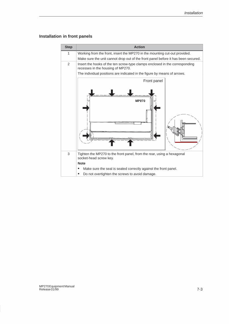
Installation
7-3MP270 Equipment ManualRelease 01/99
Installation in front panels
Step Action
1 Working from the front, insert the MP270 in the mounting cut-out provided.
Make sure the unit cannot drop out of the front panel before it has been secured.
2 Insert the hooks of the ten screw-type clamps enclosed in the correspondingrecesses in the housing of MP270.
The individual positions are indicated in the figure by means of arrows.
Front panel
3 Tighten the MP270 to the front panel, from the rear, using a hexagonalsocket-head screw key.
Note
� Make sure the seal is seated correctly against the front panel.
� Do not overtighten the screws to avoid damage.
Installation
7-4MP270 Equipment Manual
Release 01/99
7.2 Electrical Installation
Electrical connections
The MP270 requires electrical connections
� to the power supply,
� to the configuration computer (PU or PC),
� to the PLC,
� to the printer.
The electrical connections to the PU/PC is required purely for downloading theruntime software ProTool/Pro RT and configuration data. Following theconfiguration and test phases, a serial printer can be connected to the MP270instead of the configuration computer.
EMC compatible installation
A precondition for error-free operation is an EMC compatible hardware design ofthe PLC and the use of interference-proof cables. The guidelines oninterference-free design of the PLCs apply equally to installation of the MP270.
!Caution
� Only shielded cables are permitted for all signal connections.
� Screw or lock all plug connections.
� Do not install signal lines in the same cable ducts as power cables.
� Siemens AG refuses to accept liability for malfunctions and damage arisingfrom use of self-made cables or cables from other manufacturers.
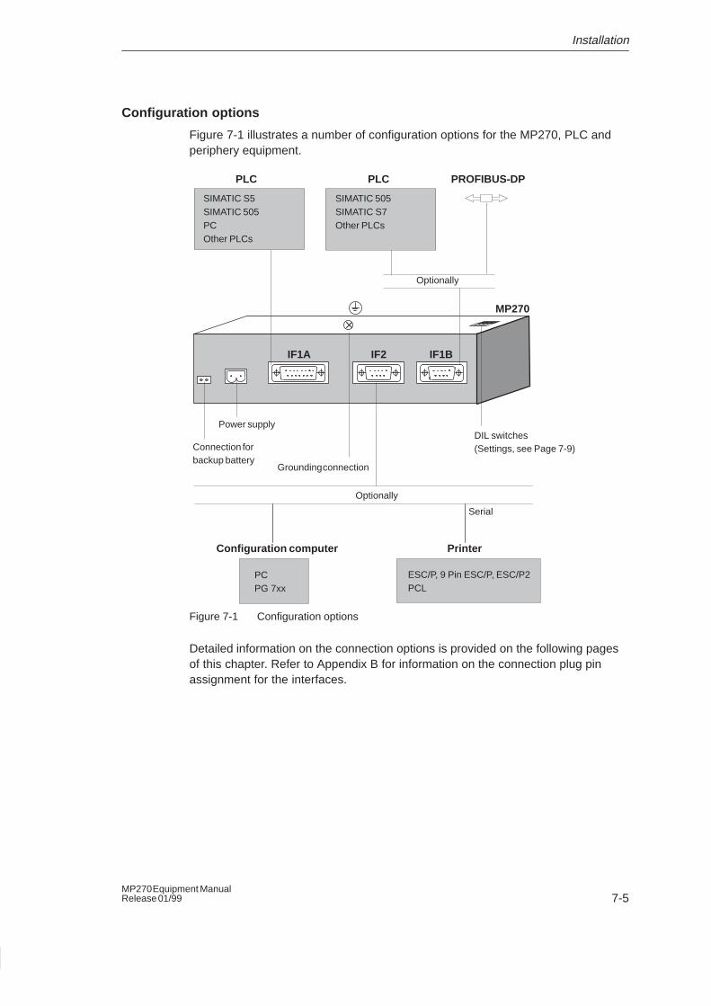
Installation
7-5MP270 Equipment ManualRelease 01/99
Configuration options
Figure 7-1 illustrates a number of configuration options for the MP270, PLC andperiphery equipment.
IF1A IF2 IF1B
MP270
Power supply
Connection forbackup battery
Optionally
Optionally
PLC PLC PROFIBUS-DP
SIMATIC S5SIMATIC 505PCOther PLCs
SIMATIC 505SIMATIC S7Other PLCs
PCPG 7xx
ESC/P, 9 Pin ESC/P, ESC/P2PCL
Configuration computer Printer
Serial
DIL switches(Settings, see Page 7-9)
Grounding connection
Figure 7-1 Configuration options
Detailed information on the connection options is provided on the following pagesof this chapter. Refer to Appendix B for information on the connection plug pinassignment for the interfaces.
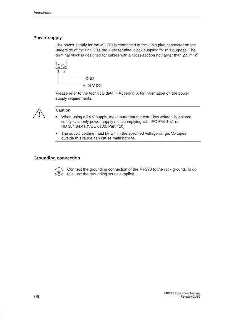
Installation
7-6MP270 Equipment Manual
Release 01/99
Power supply
The power supply for the MP270 is connected at the 2-pin plug connector on theunderside of the unit. Use the 2-pin terminal block supplied for this purpose. Theterminal block is designed for cables with a cross-section not larger than 2.5 mm2.
GND
+ 24 V DC
1 2
Please refer to the technical data in Appendix A for information on the powersupply requirements.
!Caution
� When using a 24 V supply, make sure that the extra-low voltage is isolatedsafely. Use only power supply units complying with IEC 364-4-41 orHD 384.04.41 (VDE 0100, Part 410).
� The supply voltage must be within the specified voltage range. Voltagesoutside this range can cause malfunctions.
Grounding connection
Connect the grounding connection of the MP270 to the rack ground. To dothis, use the grounding screw supplied.
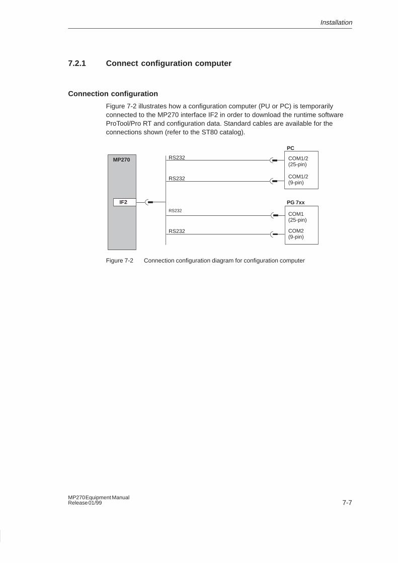
Installation
7-7MP270 Equipment ManualRelease 01/99
7.2.1 Connect configuration computer
Connection configuration
Figure 7-2 illustrates how a configuration computer (PU or PC) is temporarilyconnected to the MP270 interface IF2 in order to download the runtime softwareProTool/Pro RT and configuration data. Standard cables are available for theconnections shown (refer to the ST80 catalog).
RS232
RS232
RS232
COM1/2(25-pin)
COM1(25-pin)
COM2(9-pin)
IF2
PC
PG 7xx
MP270
RS232 COM1/2(9-pin)
Figure 7-2 Connection configuration diagram for configuration computer
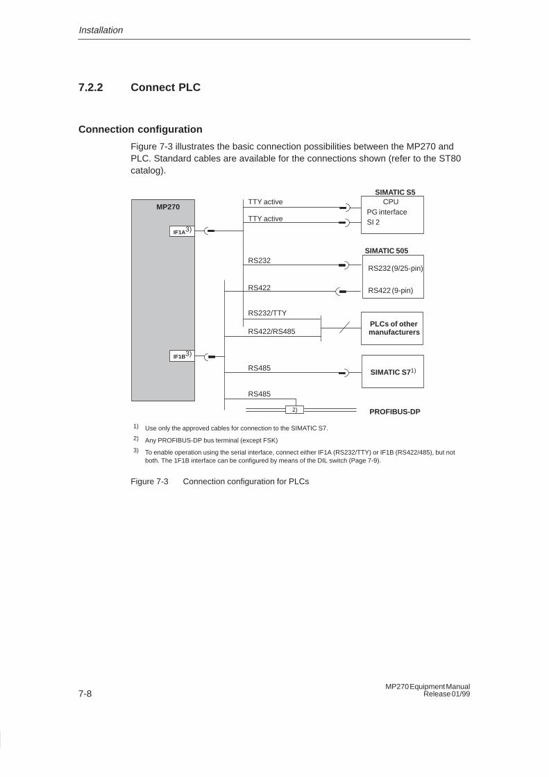
Installation
7-8MP270 Equipment Manual
Release 01/99
7.2.2 Connect PLC
Connection configuration
Figure 7-3 illustrates the basic connection possibilities between the MP270 andPLC. Standard cables are available for the connections shown (refer to the ST80catalog).
TTY activePG interfaceSI 2
RS232 (9/25-pin)
RS422 (9-pin)
SIMATIC S5
TTY active
RS232
PLCs of othermanufacturers
RS422
RS422/RS485
CPU
SIMATIC 505
PROFIBUS-DP
SIMATIC S71)
RS232/TTY
1) Use only the approved cables for connection to the SIMATIC S7.
2) Any PROFIBUS-DP bus terminal (except FSK)
3) To enable operation using the serial interface, connect either IF1A (RS232/TTY) or IF1B (RS422/485), but notboth. The 1F1B interface can be configured by means of the DIL switch (Page 7-9).
2)
IF1A3)
IF1B3)
RS485
RS485
MP270
Figure 7-3 Connection configuration for PLCs
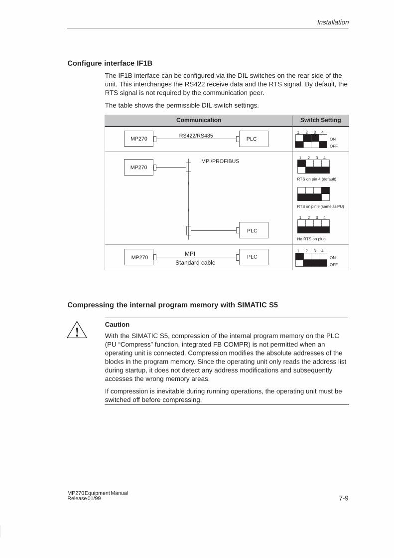
Installation
7-9MP270 Equipment ManualRelease 01/99
Configure interface IF1B
The IF1B interface can be configured via the DIL switches on the rear side of theunit. This interchanges the RS422 receive data and the RTS signal. By default, theRTS signal is not required by the communication peer.
The table shows the permissible DIL switch settings.
Communication Switch Setting
PLCRS422/RS485MP270 ON
OFF
1 2 3 4
MPI/PROFIBUSMP270
RTS on pin 4 (default)
1 2 3 4
RTS on pin 9 (same as PU)
PLC
No RTS on plug
1 2 3 4
PLCMPI
Standard cableMP270 ON
OFF
1 2 3 4
Compressing the internal program memory with SIMATIC S5
!Caution
With the SIMATIC S5, compression of the internal program memory on the PLC(PU “Compress” function, integrated FB COMPR) is not permitted when anoperating unit is connected. Compression modifies the absolute addresses of theblocks in the program memory. Since the operating unit only reads the address listduring startup, it does not detect any address modifications and subsequentlyaccesses the wrong memory areas.
If compression is inevitable during running operations, the operating unit must beswitched off before compressing.
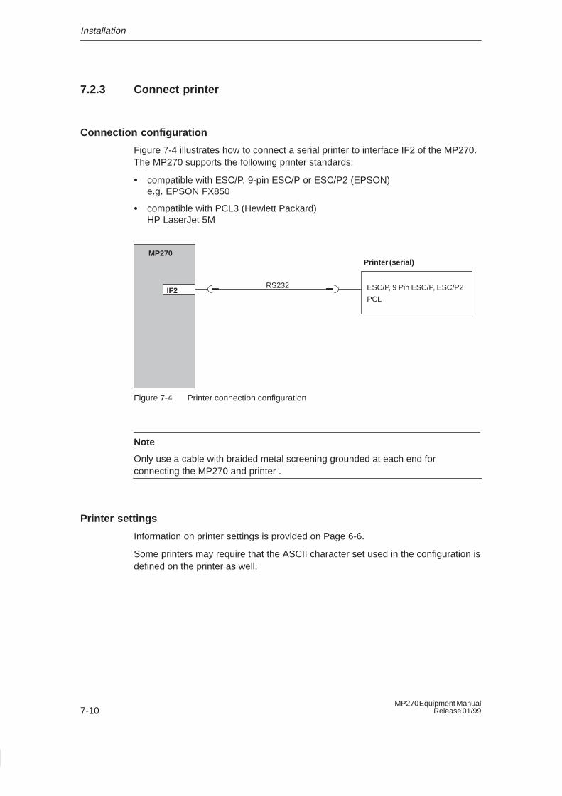
Installation
7-10MP270 Equipment Manual
Release 01/99
7.2.3 Connect printer
Connection configuration
Figure 7-4 illustrates how to connect a serial printer to interface IF2 of the MP270.The MP270 supports the following printer standards:
� compatible with ESC/P, 9-pin ESC/P or ESC/P2 (EPSON) e.g. EPSON FX850
� compatible with PCL3 (Hewlett Packard) HP LaserJet 5M
IF2
Printer (serial)
ESC/P, 9 Pin ESC/P, ESC/P2
PCL
RS232
MP270
Figure 7-4 Printer connection configuration
Note
Only use a cable with braided metal screening grounded at each end forconnecting the MP270 and printer .
Printer settings
Information on printer settings is provided on Page 6-6.
Some printers may require that the ASCII character set used in the configuration isdefined on the printer as well.
8-1MP270 Equipment ManualRelease 01/99
Unit Description
In this chapter
This chapter provides information on:
� Dimensions (Page 8-2),
� Operating and display elements (Page 8-3),
� Connection elements (Page 8-4),
� Communication options (Page 8-5),
� Labeling the function keys (Page 8-6).
8
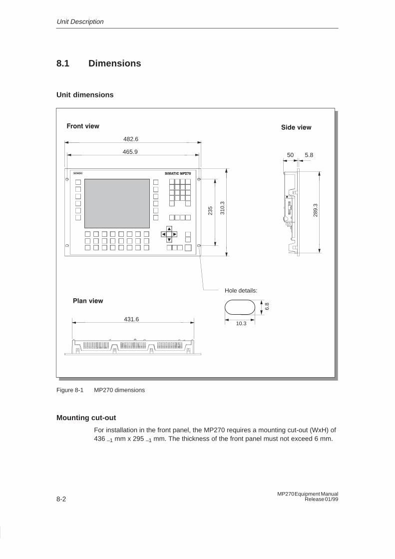
Unit Description
8-2MP270 Equipment Manual
Release 01/99
8.1 Dimensions
Unit dimensions
Side viewFront view
Plan view
Hole details:
6.8
10.3
482.6
465.9
310.
3
235
5.850
431.628
9.3
Figure 8-1 MP270 dimensions
Mounting cut-out
For installation in the front panel, the MP270 requires a mounting cut-out (WxH) of436 –1 mm x 295 –1 mm. The thickness of the front panel must not exceed 6 mm.
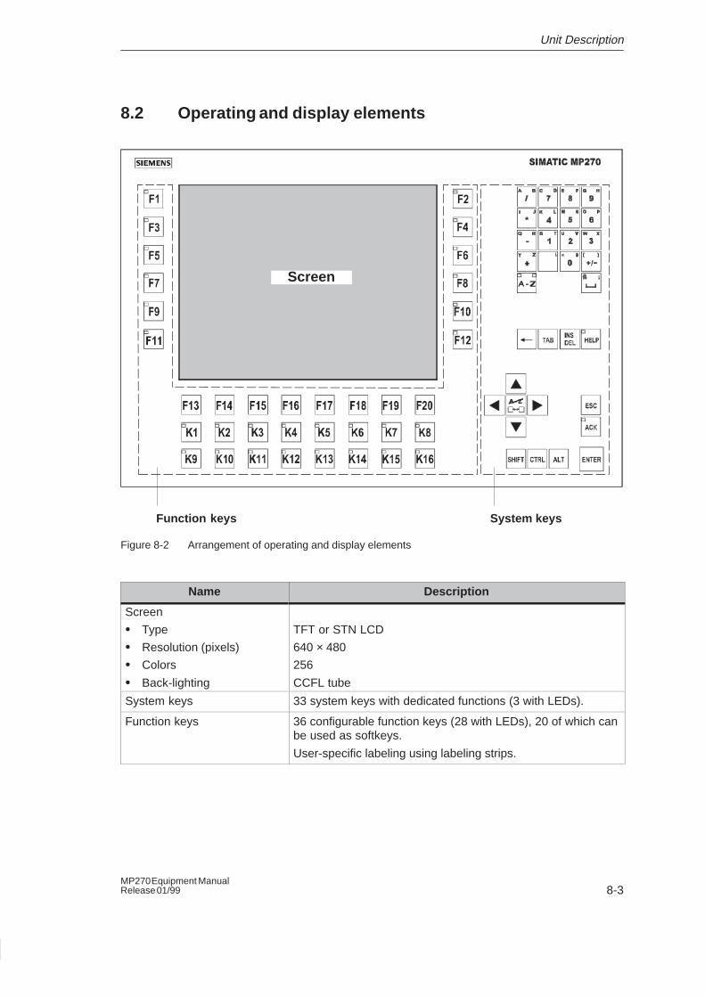
Unit Description
8-3MP270 Equipment ManualRelease 01/99
8.2 Operating and display elements
Screen
Function keys System keys
Figure 8-2 Arrangement of operating and display elements
Name Description
Screen
� Type
� Resolution (pixels)
� Colors
� Back-lighting
TFT or STN LCD
640 × 480
256
CCFL tube
System keys 33 system keys with dedicated functions (3 with LEDs).
Function keys 36 configurable function keys (28 with LEDs), 20 of which canbe used as softkeys.
User-specific labeling using labeling strips.
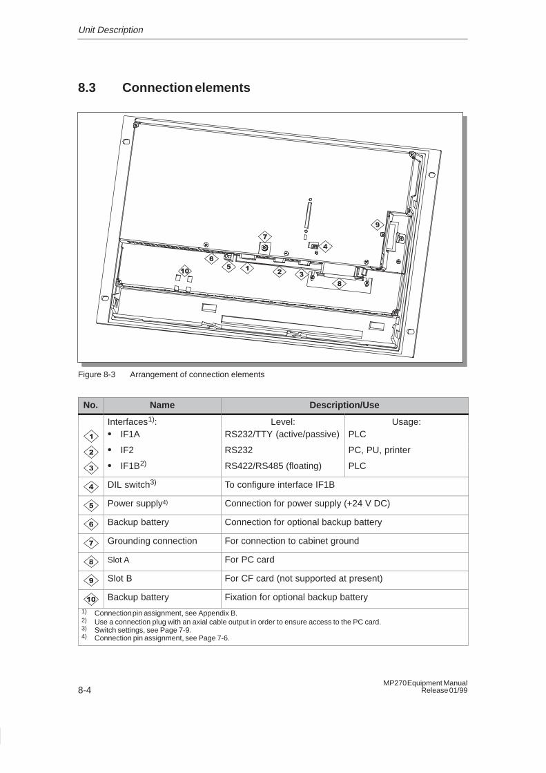
Unit Description
8-4MP270 Equipment Manual
Release 01/99
8.3 Connection elements
Figure 8-3 Arrangement of connection elements
No. Name Description/Use
Interfaces1): Level: Usage:� IF1A RS232/TTY (active/passive) PLC
� IF2 RS232 PC, PU, printer
� IF1B2) RS422/RS485 (floating) PLC
DIL switch3) To configure interface IF1B
Power supply4) Connection for power supply (+24 V DC)
Backup battery Connection for optional backup battery
Grounding connection For connection to cabinet ground
Slot A For PC card
Slot B For CF card (not supported at present)
Backup battery Fixation for optional backup battery1) Connection pin assignment, see Appendix B.2) Use a connection plug with an axial cable output in order to ensure access to the PC card.3) Switch settings, see Page 7-9.4) Connection pin assignment, see Page 7-6.
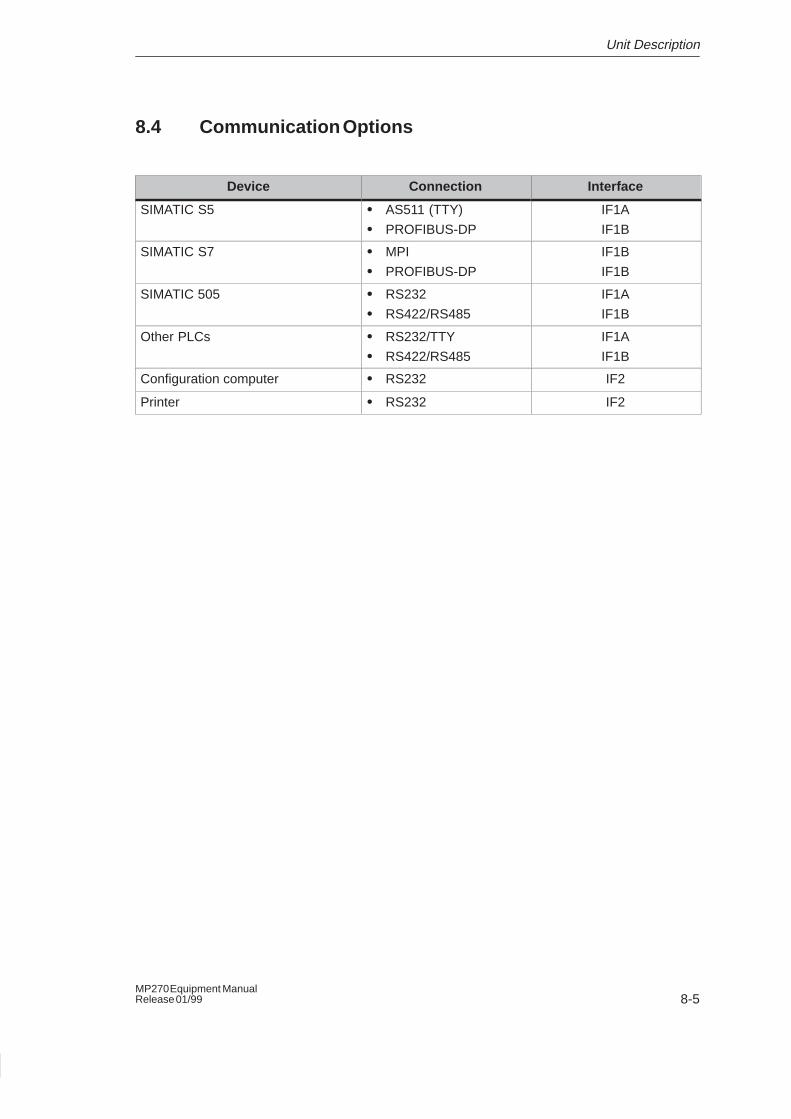
Unit Description
8-5MP270 Equipment ManualRelease 01/99
8.4 Communication Options
Device Connection Interface
SIMATIC S5 � AS511 (TTY)
� PROFIBUS-DP
IF1A
IF1B
SIMATIC S7 � MPI
� PROFIBUS-DP
IF1B
IF1B
SIMATIC 505 � RS232
� RS422/RS485
IF1A
IF1B
Other PLCs � RS232/TTY
� RS422/RS485
IF1A
IF1B
Configuration computer � RS232 IF2
Printer � RS232 IF2
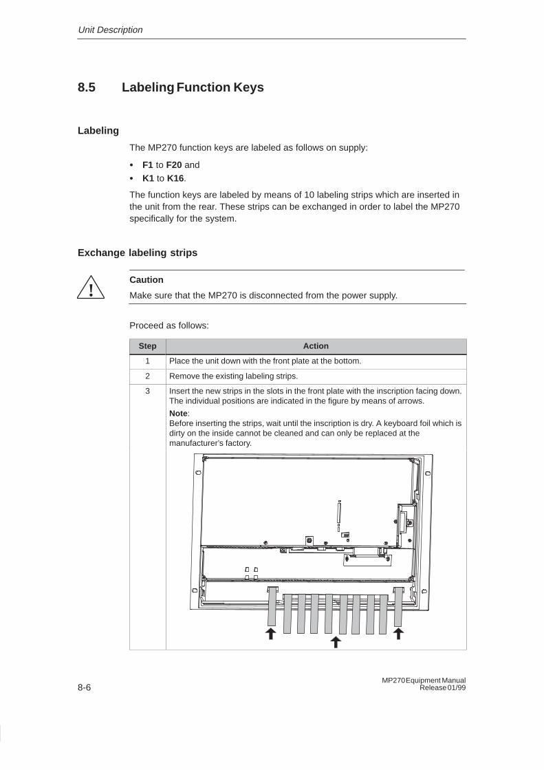
Unit Description
8-6MP270 Equipment Manual
Release 01/99
8.5 Labeling Function Keys
Labeling
The MP270 function keys are labeled as follows on supply:
� F1 to F20 and
� K1 to K16.
The function keys are labeled by means of 10 labeling strips which are inserted inthe unit from the rear. These strips can be exchanged in order to label the MP270specifically for the system.
Exchange labeling strips
!Caution
Make sure that the MP270 is disconnected from the power supply.
Proceed as follows:
Step Action
1 Place the unit down with the front plate at the bottom.
2 Remove the existing labeling strips.
3 Insert the new strips in the slots in the front plate with the inscription facing down.The individual positions are indicated in the figure by means of arrows.
Note :Before inserting the strips, wait until the inscription is dry. A keyboard foil which isdirty on the inside cannot be cleaned and can only be replaced at themanufacturer’s factory.
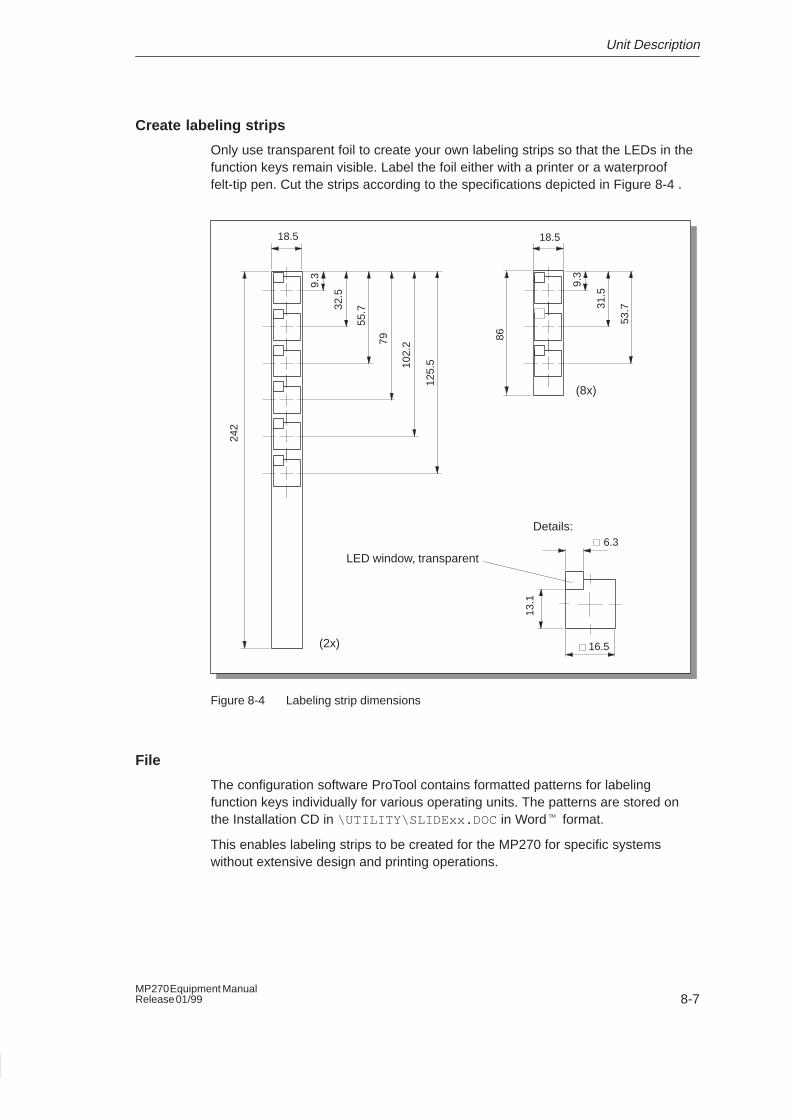
Unit Description
8-7MP270 Equipment ManualRelease 01/99
Create labeling strips
Only use transparent foil to create your own labeling strips so that the LEDs in thefunction keys remain visible. Label the foil either with a printer or a waterprooffelt-tip pen. Cut the strips according to the specifications depicted in Figure 8-4 .
Details:13
.16.3
16.5
18.5 18.5
32.5
55.7
9.3
79
102.
2
125.
5
31.5
53.7
9.3
86
242
(2x)
(8x)
LED window, transparent
Figure 8-4 Labeling strip dimensions
File
The configuration software ProTool contains formatted patterns for labelingfunction keys individually for various operating units. The patterns are stored onthe Installation CD in \UTILITY\SLIDExx.DOC in Word� format.
This enables labeling strips to be created for the MP270 for specific systemswithout extensive design and printing operations.

Unit Description
8-8MP270 Equipment Manual
Release 01/99
9-1MP270 Equipment ManualRelease 01/99
Options
In this chapter
This chapter provides information on the options available with which to retrofit theMP270. The following options are available:
� Memory cards
� Backup battery
9
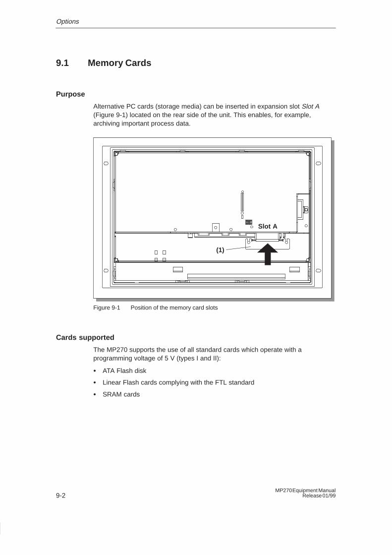
Options
9-2MP270 Equipment Manual
Release 01/99
9.1 Memory Cards
Purpose
Alternative PC cards (storage media) can be inserted in expansion slot Slot A(Figure 9-1) located on the rear side of the unit. This enables, for example,archiving important process data.
Slot A
(1)
Figure 9-1 Position of the memory card slots
Cards supported
The MP270 supports the use of all standard cards which operate with aprogramming voltage of 5 V (types I and II):
� ATA Flash disk
� Linear Flash cards complying with the FTL standard
� SRAM cards
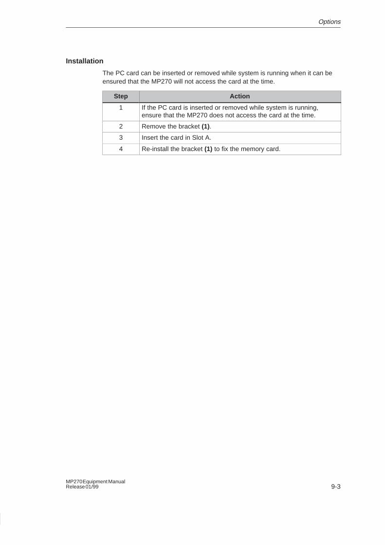
Options
9-3MP270 Equipment ManualRelease 01/99
Installation
The PC card can be inserted or removed while system is running when it can beensured that the MP270 will not access the card at the time.
Step Action
1 If the PC card is inserted or removed while system is running,ensure that the MP270 does not access the card at the time.
2 Remove the bracket (1).
3 Insert the card in Slot A.
4 Re-install the bracket (1) to fix the memory card.
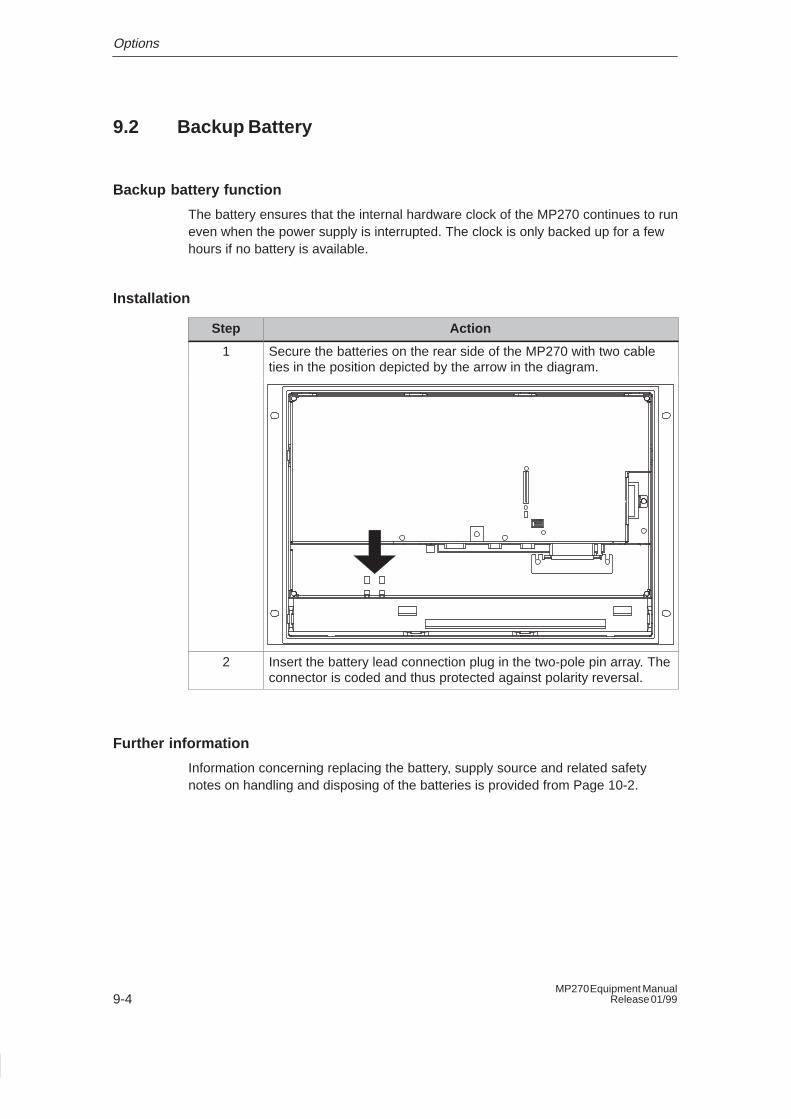
Options
9-4MP270 Equipment Manual
Release 01/99
9.2 Backup Battery
Backup battery function
The battery ensures that the internal hardware clock of the MP270 continues to runeven when the power supply is interrupted. The clock is only backed up for a fewhours if no battery is available.
Installation
Step Action
1 Secure the batteries on the rear side of the MP270 with two cableties in the position depicted by the arrow in the diagram.
2 Insert the battery lead connection plug in the two-pole pin array. Theconnector is coded and thus protected against polarity reversal.
Further information
Information concerning replacing the battery, supply source and related safetynotes on handling and disposing of the batteries is provided from Page 10-2.
10-1MP270 Equipment ManualRelease 01/99
Maintenance/Upkeep
Scope
The MP270 is has been designed for low maintenance operation. Maintenance ofthe unit is limited to
� regular cleaning of the keyboard foil and screen,
� changing the optional backup battery.
10.1 Clean Screen and Keyboard Foil
Preparation
Clean the MP270 screen and keyboard foil at regular intervals using a damp cloth.Do not clean the unit while it is turned on. This ensures that functions are notinadvertently triggered on touching the keys.
Cleaning agents
Only use water and washing up liquid or screen cleaning foam to dampen cloths.Never spray the cleaning agent directly onto the screen, but onto the cleaningcloth. Never use aggressive solvents or scouring powder.
10
Maintenance/Upkeep
10-2MP270 Equipment Manual
Release 01/99
10.2 Replacing the Optional Backup Battery
Backup battery function
An optional backup battery is available for the MP270 (refer to Chapter 9). Thebattery ensures that the internal hardware clock continues to run even when thepower supply is interrupted.
Under normal operating conditions, the battery has a service life of approx. 4years.
Supply source
The battery can be ordered from the Siemens spare parts service. It is shippedready for installation with a lead and connector. Please refer to our catalog ST80for the order number.
Before replacing
Observe the following before changing the battery:
!Caution
� Change the battery while power is still being supplied to ensure the internalhardware clock continues to run.
� The battery must be changed by a properly qualified person.
� Before replacing the battery, refer to the ESD Guidelines in Appendix D.
Maintenance/Upkeep
10-3MP270 Equipment ManualRelease 01/99
Action
Step Action
1 Remove the battery lead connector from the two-pin plug connectoron the unit.
2 The battery is normally secured by means of two cable ties on therear side of the MP270. Cut the cable ties, using pliers for instance,and remove the empty battery.
3 Secure the new battery by means of two cable ties on the rear sideof the MP270.
4 Insert the battery lead connector back into the plug connector. Theconnector is coded and thus protected against polarity reversal.
General notes
Please observe the following safety notes to ensure correct handling and disposalof lithium batteries:
!Warning
� If the lithium battery is not handled properly, there is a risk of explosion.
� Batteries
– should never be charged
– should not be opened
– should not be short-circuited
– should be safeguarded against polarity reversal
– should not be exposed to temperatures in excess of 100 °C– should be protected against direct sunlight.
� Do not allow condensation to form on batteries.
� Should shipping become necessary, ensure compliance with the DangerousChemicals Ordinance for the carrier concerned (coding obligation).
� Treat used lithium batteries as special waste. Pack them in separate leakproofplastic bags to dispose of them.

Maintenance/Upkeep
10-4MP270 Equipment Manual
Release 01/99
APPENDICES
A Technical Data
B Interface Assignments
C System Messages
D ESD Guidelines
E SIMATIC HMI Documentation
F Siemens Worldwide

APPENDICES
J-2MP270 Equipment Manual
Release 01/99
A-1MP270 Equipment ManualRelease 01/99
Technical Data
In this Appendix
This Appendix contains the following technical data for the MP270:
� Housing
� Processor
� Memory
� Software
� Display
� Keyboard
� Power supply
� Backup battery (option)
� Ambient conditions
� Noise immunity / Noise transmission
� Approvals
A
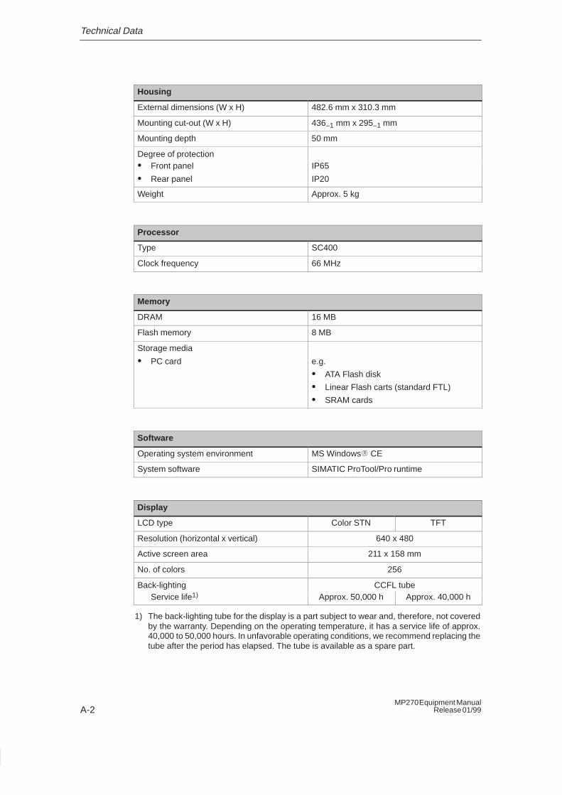
Technical Data
A-2MP270 Equipment Manual
Release 01/99
Housing
External dimensions (W x H) 482.6 mm x 310.3 mm
Mounting cut-out (W x H) 436–1 mm x 295–1 mm
Mounting depth 50 mm
Degree of protection� Front panel
� Rear panel
IP65
IP20
Weight Approx. 5 kg
Processor
Type SC400
Clock frequency 66 MHz
Memory
DRAM 16 MB
Flash memory 8 MB
Storage media
� PC card e.g.
� ATA Flash disk
� Linear Flash carts (standard FTL)
� SRAM cards
Software
Operating system environment MS Windows� CE
System software SIMATIC ProTool/Pro runtime
Display
LCD type Color STN TFT
Resolution (horizontal x vertical) 640 x 480
Active screen area 211 x 158 mm
No. of colors 256
Back-lighting CCFL tubeService life1) Approx. 50,000 h Approx. 40,000 h
1) The back-lighting tube for the display is a part subject to wear and, therefore, not coveredby the warranty. Depending on the operating temperature, it has a service life of approx.40,000 to 50,000 hours. In unfavorable operating conditions, we recommend replacing thetube after the period has elapsed. The tube is available as a spare part.
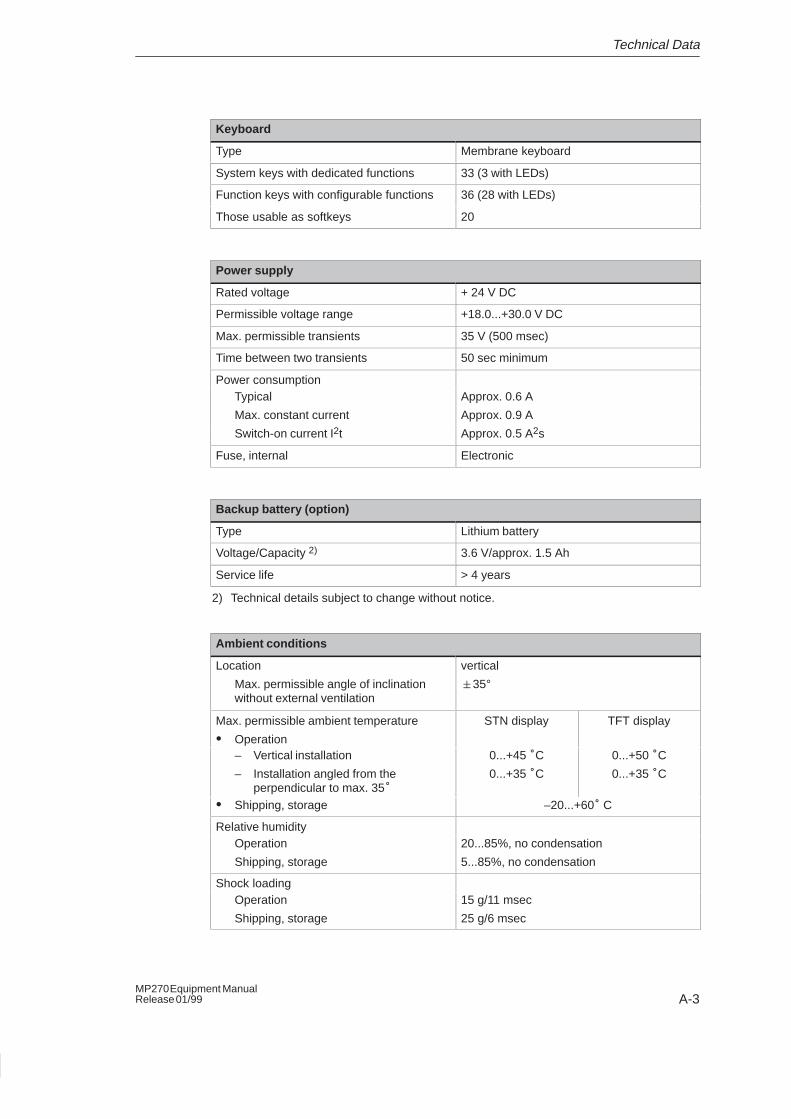
Technical Data
A-3MP270 Equipment ManualRelease 01/99
Keyboard
Type Membrane keyboard
System keys with dedicated functions 33 (3 with LEDs)
Function keys with configurable functions 36 (28 with LEDs)
Those usable as softkeys 20
Power supply
Rated voltage + 24 V DC
Permissible voltage range +18.0...+30.0 V DC
Max. permissible transients 35 V (500 msec)
Time between two transients 50 sec minimum
Power consumptionTypical
Max. constant current
Approx. 0.6 A
Approx. 0.9 A
Switch-on current I2t Approx. 0.5 A2s
Fuse, internal Electronic
Backup battery (option)
Type Lithium battery
Voltage/Capacity 2) 3.6 V/approx. 1.5 Ah
Service life > 4 years
2) Technical details subject to change without notice.
Ambient conditions
Location
Max. permissible angle of inclinationwithout external ventilation
vertical
�35°
Max. permissible ambient temperature
� Operation
STN display TFT display
– Vertical installation
– Installation angled from theperpendicular to max. 35°
0...+45 °C
0...+35 °C
0...+50 °C
0...+35 °C
� Shipping, storage –20...+60° C
Relative humidityOperation
Shipping, storage
20...85%, no condensation
5...85%, no condensation
Shock loadingOperation
Shipping, storage
15 g/11 msec
25 g/6 msec
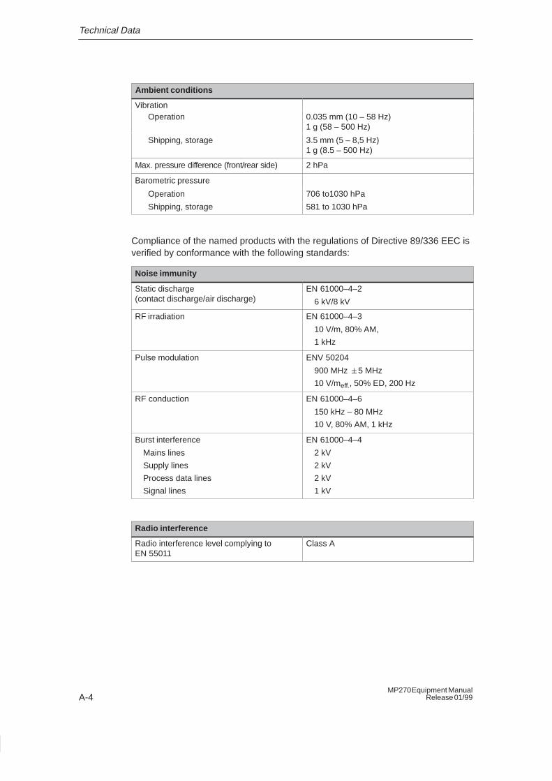
Technical Data
A-4MP270 Equipment Manual
Release 01/99
Ambient conditions
VibrationOperation 0.035 mm (10 – 58 Hz)
1 g (58 – 500 Hz)
Shipping, storage 3.5 mm (5 – 8,5 Hz)1 g (8.5 – 500 Hz)
Max. pressure difference (front/rear side) 2 hPa
Barometric pressure
Operation
Shipping, storage
706 to1030 hPa
581 to 1030 hPa
Compliance of the named products with the regulations of Directive 89/336 EEC isverified by conformance with the following standards:
Noise immunity
Static discharge (contact discharge/air discharge)
EN 61000–4–2
6 kV/8 kV
RF irradiation EN 61000–4–3
10 V/m, 80% AM,
1 kHz
Pulse modulation ENV 50204
900 MHz �5 MHz
10 V/meff., 50% ED, 200 Hz
RF conduction EN 61000–4–6
150 kHz – 80 MHz
10 V, 80% AM, 1 kHz
Burst interference
Mains lines
Supply lines
Process data lines
Signal lines
EN 61000–4–4
2 kV
2 kV
2 kV
1 kV
Radio interference
Radio interference level complying to EN 55011
Class A
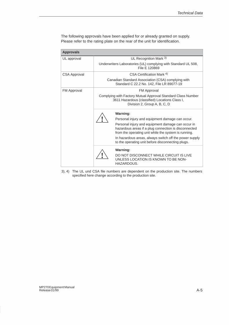
Technical Data
A-5MP270 Equipment ManualRelease 01/99
The following approvals have been applied for or already granted on supply.Please refer to the rating plate on the rear of the unit for identification.
Approvals
UL approval UL Recognition Mark 3)
Underwriters Laboratories (UL) complying with Standard UL 508, File E 120869
CSA Approval CSA Certification Mark 4)
Canadian Standard Association (CSA) complying with Standard C 22.2 No. 142, File LR 89077-19
FM Approval FM Approval
Complying with Factory Mutual Approval Standard Class Number3611 Hazardous (classified) Locations Class I,
Division 2, Group A, B, C, D
Warning:
Personal injury and equipment damage can occur.
Personal injury and equipment damage can occur inhazardous areas if a plug connection is disconnectedfrom the operating unit while the system is running.
In hazardous areas, always switch off the power supplyto the operating unit before disconnecting plugs.
!
Warning:
DO NOT DISCONNECT WHILE CIRCUIT IS LIVEUNLESS LOCATION IS KNOWN TO BE NON-HAZARDOUS.
!
3), 4) The UL und CSA file numbers are dependent on the production site. The numbersspecified here change according to the production site.

Technical Data
A-6MP270 Equipment Manual
Release 01/99
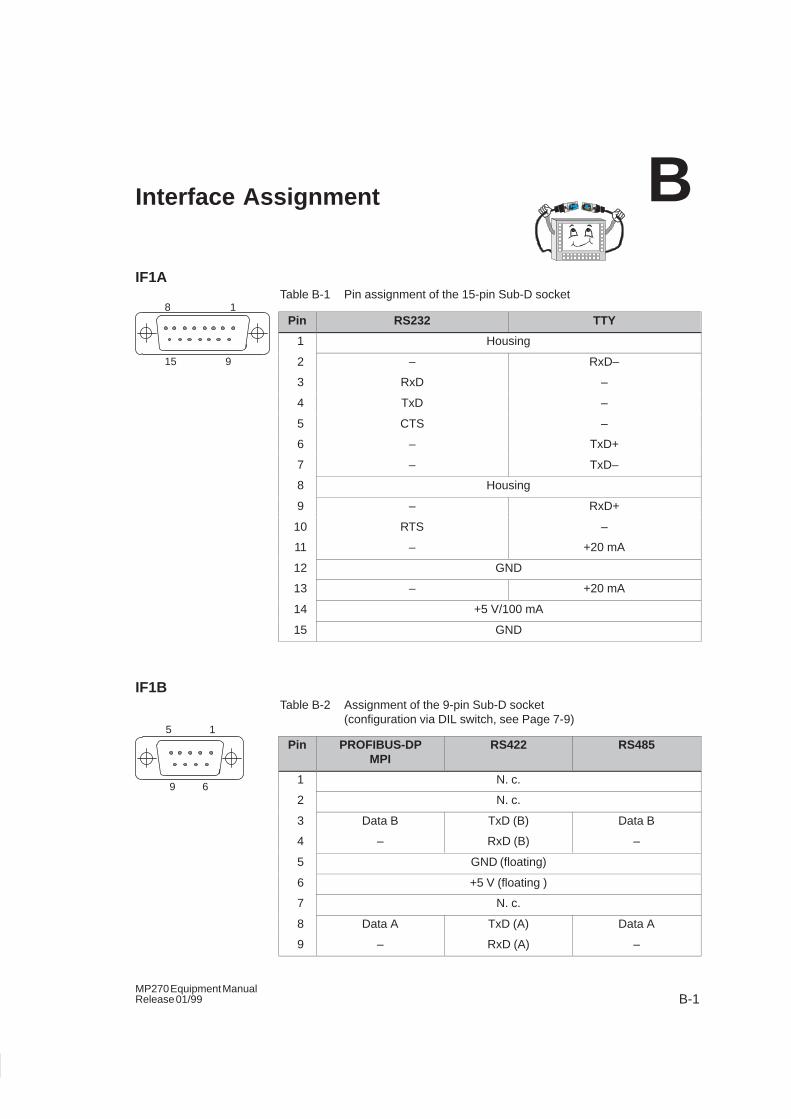
B-1MP270 Equipment ManualRelease 01/99
Interface Assignment
IF1ATable B-1 Pin assignment of the 15-pin Sub-D socket
Pin RS232 TTY
1 Housing
2 – RxD–
3 RxD –
4 TxD –
5 CTS –
6 – TxD+
7 – TxD–
8 Housing
9 – RxD+
10 RTS –
11 – +20 mA
12 GND
13 – +20 mA
14 +5 V/100 mA
15 GND
IF1BTable B-2 Assignment of the 9-pin Sub-D socket
(configuration via DIL switch, see Page 7-9)
Pin PROFIBUS-DPMPI
RS422 RS485
1 N. c.
2 N. c.
3 Data B TxD (B) Data B
4 – RxD (B) –
5 GND (floating)
6 +5 V (floating )
7 N. c.
8 Data A TxD (A) Data A
9 – RxD (A) –
B
8 1
15 9
5 1
9 6
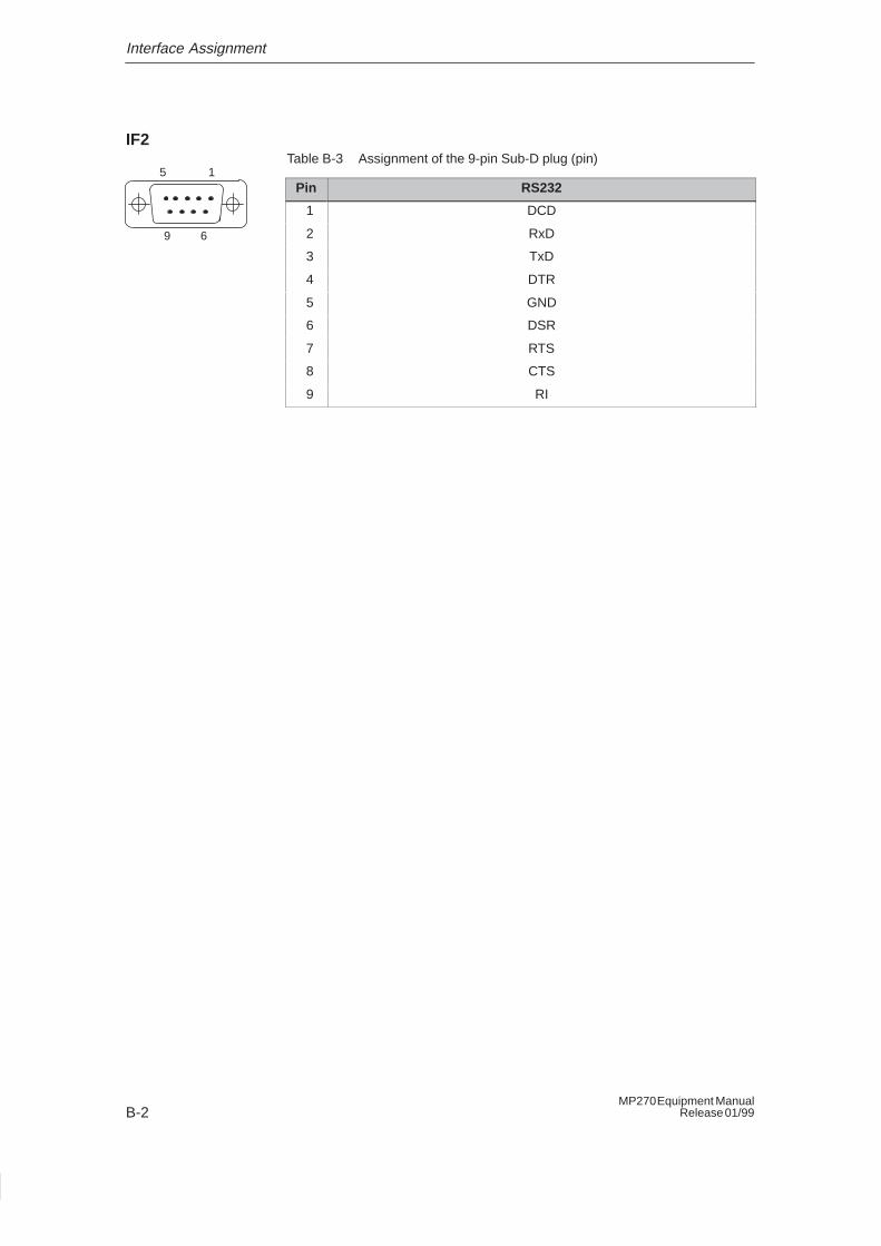
Interface Assignment
B-2MP270 Equipment Manual
Release 01/99
IF2Table B-3 Assignment of the 9-pin Sub-D plug (pin)
Pin RS232
1 DCD
2 RxD
3 TxD
4 DTR
5 GND
6 DSR
7 RTS
8 CTS
9 RI
5 1
9 6
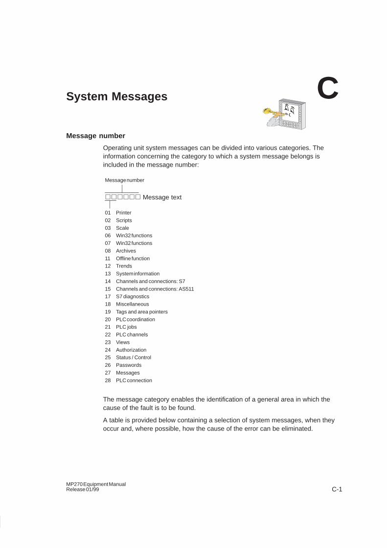
C-1MP270 Equipment ManualRelease 01/99
System Messages
Message number
Operating unit system messages can be divided into various categories. Theinformation concerning the category to which a system message belongs isincluded in the message number:
������ Message text
Message number
01 Printer
02 Scripts
03 Scale06 Win32 functions
07 Win32 functions
08 Archives
11 Offline function12 Trends
13 System information
14 Channels and connections: S7
15 Channels and connections: AS51117 S7 diagnostics
18 Miscellaneous
19 Tags and area pointers
20 PLC coordination21 PLC jobs
22 PLC channels
23 Views
24 Authorization25 Status / Control
26 Passwords
27 Messages
28 PLC connection
The message category enables the identification of a general area in which thecause of the fault is to be found.
A table is provided below containing a selection of system messages, when theyoccur and, where possible, how the cause of the error can be eliminated.
C
System Messages
C-2MP270 Equipment Manual
Release 01/99
Note
System messages are displayed in the language selected in the configuration.
Procedure in the case of “internal errors”
Adopt the following procedure for all system messages referring to “internal errors”:
1. Switch the operating unit off, set the PLC to the STOP status and then start upboth units again.
2. Download the configuration again and then restart the PLC and operating unit.
3. If the fault occurs again, please contact your nearest Siemens representative.When doing so, please quote the number of the error that has occurred and anytags referred to in the message.
System message parameters
The system messages may contain parameters which are not decoded for the userbut which are relevant in respect of the cause of an error since they provide areference to the source code from ProTool/Pro Runtime. These parameters areissued according to the text “Error code:”
Number Effect/Cause Remedy
10000 The print job could not be started or was terminatedfor an unknown reason.
The printer is incorrectly configured.
Or: There are no rights for a network printer available.
Configure the printer again.
Initiate the assignment of rights fora network printer.
10001 No printer has been installed or no standard printerconfigured.
Install a printer and/or mark one asstandard printer.
10002 The intermediate buffer for printing graphics is full. Upto two graphics can be buffered.
Do not issue print jobs so quickly insuccession.
10003 Graphics can be buffered again. –
10004 The intermediate buffer for printing lines in text mode(e.g. messages) is full. Up to 1000 lines can bebuffered.
Do not issue print jobs so quickly insuccession.
10005 Lines of text can be buffered again. –
20010 A fault has occurred in the script line specified.Execution of the script function was, therefore,terminated.
In this case, it is advisable to check any previoussystem messages too.
Select the specified script line inthe configuration.
Check tags, whether the typesused are permissible.
Check Functions, whether thenumber and types of parameterare correct.
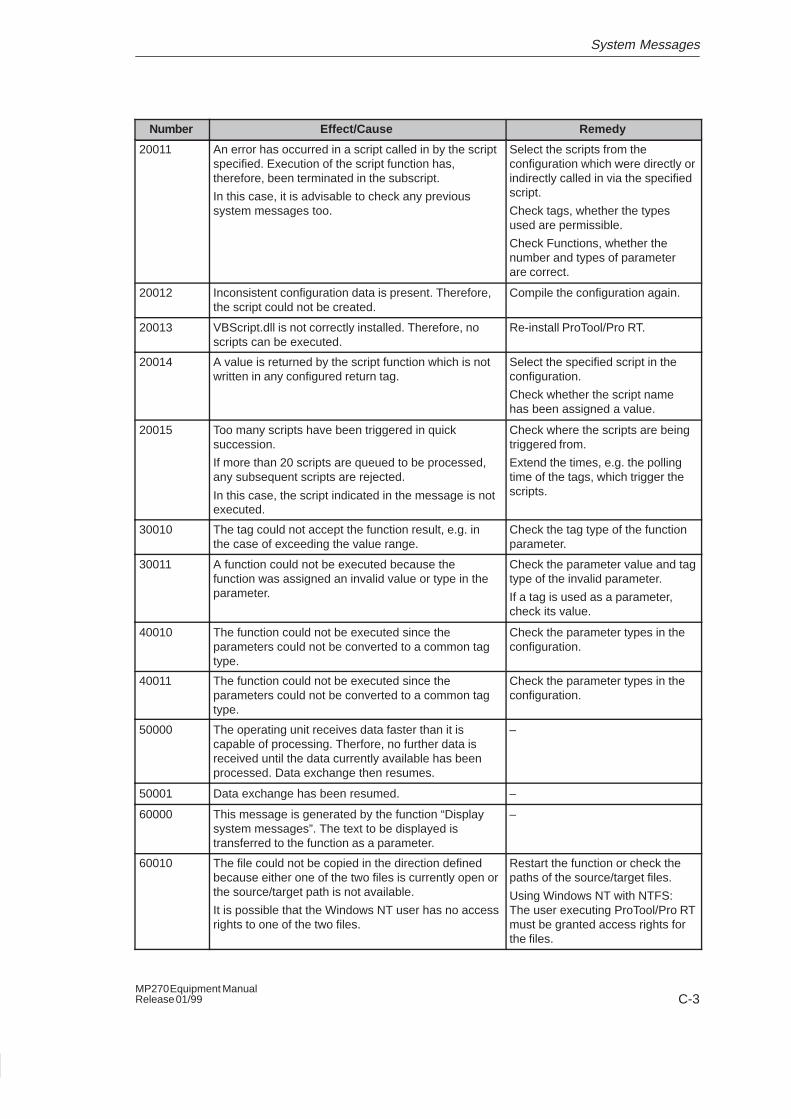
System Messages
C-3MP270 Equipment ManualRelease 01/99
RemedyEffect/CauseNumber
20011 An error has occurred in a script called in by the scriptspecified. Execution of the script function has,therefore, been terminated in the subscript.
In this case, it is advisable to check any previoussystem messages too.
Select the scripts from theconfiguration which were directly orindirectly called in via the specifiedscript.
Check tags, whether the typesused are permissible.
Check Functions, whether thenumber and types of parameterare correct.
20012 Inconsistent configuration data is present. Therefore,the script could not be created.
Compile the configuration again.
20013 VBScript.dll is not correctly installed. Therefore, noscripts can be executed.
Re-install ProTool/Pro RT.
20014 A value is returned by the script function which is notwritten in any configured return tag.
Select the specified script in theconfiguration.
Check whether the script namehas been assigned a value.
20015 Too many scripts have been triggered in quicksuccession.
If more than 20 scripts are queued to be processed,any subsequent scripts are rejected.
In this case, the script indicated in the message is notexecuted.
Check where the scripts are beingtriggered from.
Extend the times, e.g. the pollingtime of the tags, which trigger thescripts.
30010 The tag could not accept the function result, e.g. inthe case of exceeding the value range.
Check the tag type of the functionparameter.
30011 A function could not be executed because thefunction was assigned an invalid value or type in theparameter.
Check the parameter value and tagtype of the invalid parameter.
If a tag is used as a parameter,check its value.
40010 The function could not be executed since theparameters could not be converted to a common tagtype.
Check the parameter types in theconfiguration.
40011 The function could not be executed since theparameters could not be converted to a common tagtype.
Check the parameter types in theconfiguration.
50000 The operating unit receives data faster than it iscapable of processing. Therfore, no further data isreceived until the data currently available has beenprocessed. Data exchange then resumes.
–
50001 Data exchange has been resumed. –
60000 This message is generated by the function “Displaysystem messages”. The text to be displayed istransferred to the function as a parameter.
–
60010 The file could not be copied in the direction definedbecause either one of the two files is currently open orthe source/target path is not available.
It is possible that the Windows NT user has no accessrights to one of the two files.
Restart the function or check thepaths of the source/target files.
Using Windows NT with NTFS:The user executing ProTool/Pro RTmust be granted access rights forthe files.
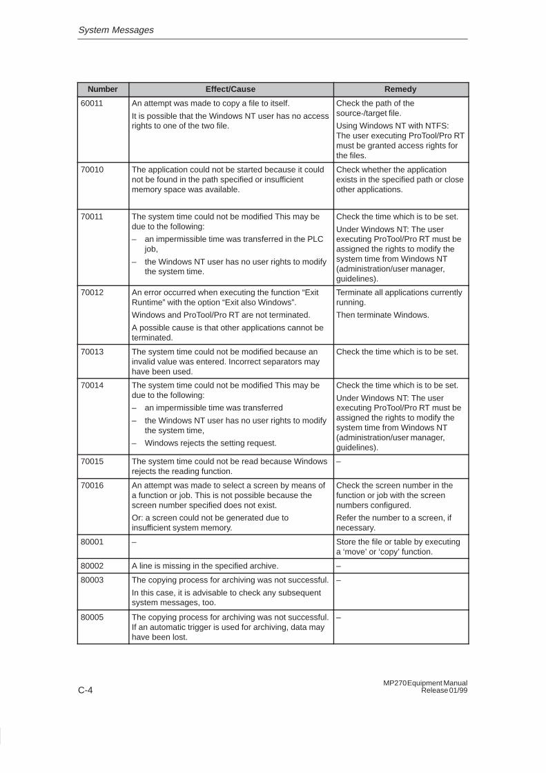
System Messages
C-4MP270 Equipment Manual
Release 01/99
RemedyEffect/CauseNumber
60011 An attempt was made to copy a file to itself.
It is possible that the Windows NT user has no accessrights to one of the two file.
Check the path of thesource-/target file.
Using Windows NT with NTFS:The user executing ProTool/Pro RTmust be granted access rights forthe files.
70010 The application could not be started because it couldnot be found in the path specified or insufficientmemory space was available.
Check whether the applicationexists in the specified path or closeother applications.
70011 The system time could not be modified This may bedue to the following:
– an impermissible time was transferred in the PLCjob,
– the Windows NT user has no user rights to modifythe system time.
Check the time which is to be set.
Under Windows NT: The userexecuting ProTool/Pro RT must beassigned the rights to modify thesystem time from Windows NT(administration/user manager,guidelines).
70012 An error occurred when executing the function “ExitRuntime” with the option “Exit also Windows”.
Windows and ProTool/Pro RT are not terminated.
A possible cause is that other applications cannot beterminated.
Terminate all applications currentlyrunning.
Then terminate Windows.
70013 The system time could not be modified because aninvalid value was entered. Incorrect separators mayhave been used.
Check the time which is to be set.
70014 The system time could not be modified This may bedue to the following:
– an impermissible time was transferred
– the Windows NT user has no user rights to modifythe system time,
– Windows rejects the setting request.
Check the time which is to be set.
Under Windows NT: The userexecuting ProTool/Pro RT must beassigned the rights to modify thesystem time from Windows NT(administration/user manager,guidelines).
70015 The system time could not be read because Windowsrejects the reading function.
–
70016 An attempt was made to select a screen by means ofa function or job. This is not possible because thescreen number specified does not exist.
Or: a screen could not be generated due toinsufficient system memory.
Check the screen number in thefunction or job with the screennumbers configured.
Refer the number to a screen, ifnecessary.
80001 – Store the file or table by executinga ‘move’ or ‘copy’ function.
80002 A line is missing in the specified archive. –
80003 The copying process for archiving was not successful.
In this case, it is advisable to check any subsequentsystem messages, too.
–
80005 The copying process for archiving was not successful.If an automatic trigger is used for archiving, data mayhave been lost.
–
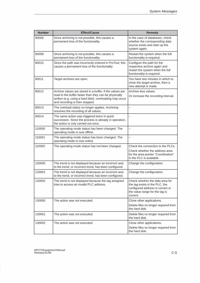
System Messages
C-5MP270 Equipment ManualRelease 01/99
RemedyEffect/CauseNumber
80006 Since archiving is not possible, this causes apermanent loss of the functionality.
In the case of databases, checkwhether the corresponding datasource exists and start up thesystem again.
80008 Since archiving is not possible, this causes apermanent loss of the functionality.
Restart the system when the fullfunctionality is required.
80010 Since the path was incorrectly entered in ProTool, thiscauses a permanent loss of the functionality.
Configure the path for therespective archive again andrestart the system when the fullfunctionality is required.
80011 Target archives are open. You have two minutes in which toclose the target archive, then anew attempt is made.
80012 Archive values are stored in a buffer. If the values areread to the buffer faster than they can be physicallywritten (e.g. using a hard disk), overloading may occurand recording is then stopped.
Archive less values.
Or increase the recording interval.
80013 The overload status no longer applies. Archivingresumes the recording of all values.
–
80014 The same action was triggered twice in quicksuccession. Since the process is already in operation,the action is only carried out once.
–
110000 The operating mode status has been changed. Theoperating mode is now offline.
–
110001 The operating mode status has been changed. Theoperating mode is now online.
–
110002 The operating mode status has not been changed. Check the connection to the PLCs.
Check whether the address areafor the area pointer “Coordination”in the PLC is available.
120000 The trend is not displayed because an incorrect axisto the trend, or incorrect trend, has been configured.
Change the configuration.
120001 The trend is not displayed because an incorrect axisto the trend, or incorrect trend, has been configured.
Change the configuration.
120002 The trend is not displayed because the tag assignedtries to access an invalid PLC address.
Check whether the data area forthe tag exists in the PLC, theconfigured address is correct orthe value range for the tag iscorrect.
130000 The action was not executed. Close other applications.
Delete files no longer required fromthe hard disk.
130001 The action was not executed. Delete files no longer required fromthe hard disk.
130002 The action was not executed. Close other applications.
Delete files no longer required fromthe hard disk.
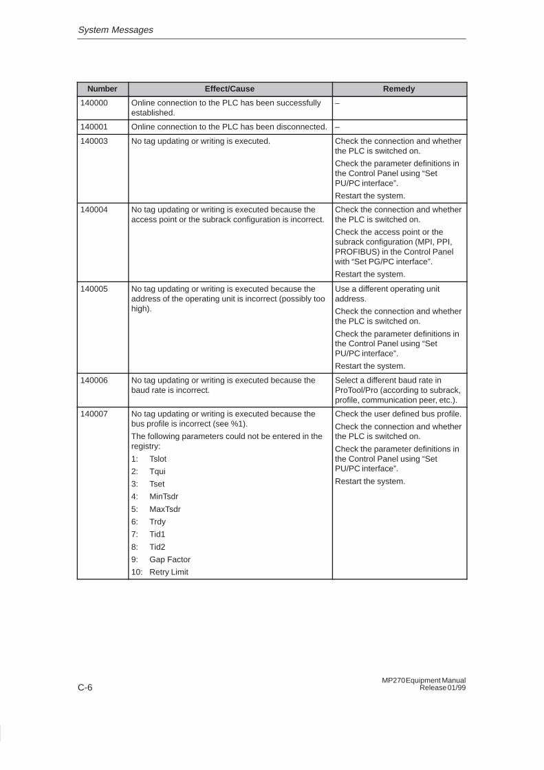
System Messages
C-6MP270 Equipment Manual
Release 01/99
RemedyEffect/CauseNumber
140000 Online connection to the PLC has been successfullyestablished.
–
140001 Online connection to the PLC has been disconnected. –
140003 No tag updating or writing is executed. Check the connection and whetherthe PLC is switched on.
Check the parameter definitions inthe Control Panel using “SetPU/PC interface”.
Restart the system.
140004 No tag updating or writing is executed because theaccess point or the subrack configuration is incorrect.
Check the connection and whetherthe PLC is switched on.
Check the access point or thesubrack configuration (MPI, PPI,PROFIBUS) in the Control Panelwith “Set PG/PC interface”.
Restart the system.
140005 No tag updating or writing is executed because theaddress of the operating unit is incorrect (possibly toohigh).
Use a different operating unitaddress.
Check the connection and whetherthe PLC is switched on.
Check the parameter definitions inthe Control Panel using “SetPU/PC interface”.
Restart the system.
140006 No tag updating or writing is executed because thebaud rate is incorrect.
Select a different baud rate inProTool/Pro (according to subrack,profile, communication peer, etc.).
140007 No tag updating or writing is executed because thebus profile is incorrect (see %1).
The following parameters could not be entered in theregistry:
1: Tslot
2: Tqui
3: Tset
4: MinTsdr
5: MaxTsdr
6: Trdy
7: Tid1
8: Tid2
9: Gap Factor
10: Retry Limit
Check the user defined bus profile.
Check the connection and whetherthe PLC is switched on.
Check the parameter definitions inthe Control Panel using “SetPU/PC interface”.
Restart the system.
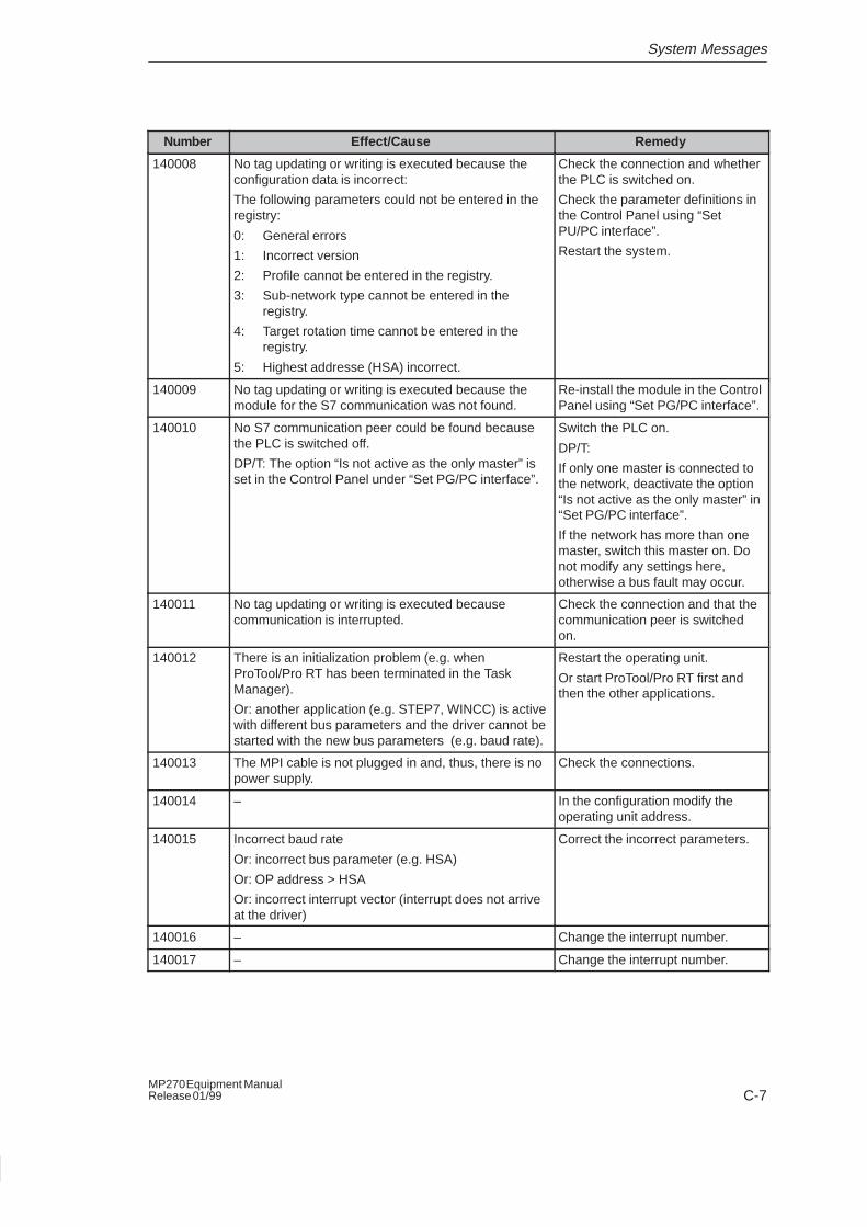
System Messages
C-7MP270 Equipment ManualRelease 01/99
RemedyEffect/CauseNumber
140008 No tag updating or writing is executed because theconfiguration data is incorrect:
The following parameters could not be entered in theregistry:
0: General errors
1: Incorrect version
2: Profile cannot be entered in the registry.
3: Sub-network type cannot be entered in theregistry.
4: Target rotation time cannot be entered in theregistry.
5: Highest addresse (HSA) incorrect.
Check the connection and whetherthe PLC is switched on.
Check the parameter definitions inthe Control Panel using “SetPU/PC interface”.
Restart the system.
140009 No tag updating or writing is executed because themodule for the S7 communication was not found.
Re-install the module in the ControlPanel using “Set PG/PC interface”.
140010 No S7 communication peer could be found becausethe PLC is switched off.
DP/T: The option “Is not active as the only master” isset in the Control Panel under “Set PG/PC interface”.
Switch the PLC on.
DP/T:
If only one master is connected tothe network, deactivate the option“Is not active as the only master” in“Set PG/PC interface”.
If the network has more than onemaster, switch this master on. Donot modify any settings here,otherwise a bus fault may occur.
140011 No tag updating or writing is executed becausecommunication is interrupted.
Check the connection and that thecommunication peer is switchedon.
140012 There is an initialization problem (e.g. whenProTool/Pro RT has been terminated in the TaskManager).
Or: another application (e.g. STEP7, WINCC) is activewith different bus parameters and the driver cannot bestarted with the new bus parameters (e.g. baud rate).
Restart the operating unit.
Or start ProTool/Pro RT first andthen the other applications.
140013 The MPI cable is not plugged in and, thus, there is nopower supply.
Check the connections.
140014 – In the configuration modify theoperating unit address.
140015 Incorrect baud rate
Or: incorrect bus parameter (e.g. HSA)
Or: OP address > HSA
Or: incorrect interrupt vector (interrupt does not arriveat the driver)
Correct the incorrect parameters.
140016 – Change the interrupt number.
140017 – Change the interrupt number.
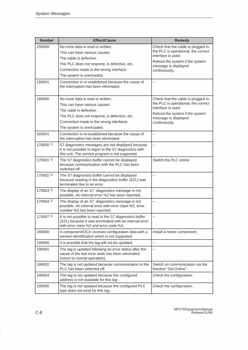
System Messages
C-8MP270 Equipment Manual
Release 01/99
RemedyEffect/CauseNumber
150000 No more data is read or written.
This can have various causes:
The cable is defective.
The PLC does not respond, is defective, etc.
Connection made to the wrong interface.
The system is overloaded.
Check that the cable is plugged in,the PLC is operational, the correctinterface is used.
Reboot the system if the systemmessage is displayedcontinuously.
150001 Connection is re-established because the cause ofthe interruption has been eliminated.
–
160000 No more data is read or written.
This can have various causes:
The cable is defective.
The PLC does not respond, is defective, etc.
Connection made to the wrong interfacet.
The system is overloaded.
Check that the cable is plugged in,the PLC is operational, the correctinterface is used.
Reboot the system if the systemmessage is displayedcontinuously.
160001 Connection is re-established because the cause ofthe interruption has been eliminated.
–
170000 1) S7 diagnostics messages are not displayed becauseit is not possible to logon to the S7 diagnostics withthis unit. The service program is not supported.
–
170001 1) The S7 diagnostics buffer cannot be displayedbecause communication with the PLC has beenswitched off.
Switch the PLC online.
170002 1) The S7 diagnostics buffer cannot be displayedbecause reading in the diagnostics buffer (SZL) wasterminated due to an error.
–
170003 1) The display of an S7 diagnostics message is notpossible. An internal error %2 has been reported.
–
170004 1) The display of an S7 diagnostics message is notpossible. An internal error with error class %2, errornumber %3 has been reported.
–
170007 1) It is not possible to read in the S7 diagnostics buffer(SZL) because it was terminated with an internal errorwith error class %2 and error code %3.
–
180000 A component/OCX receives configuration data with aversion identification which is not supported.
Install a newer component.
190000 It is possible that the tag will not be updated. –
190001 The tag is updated following an error status after thecause of the last error state has been eliminated(return to normal operation).
–
190002 The tag is not updated because communication to thePLC has been switched off.
Switch on communication via thefunction “Set Online”.
190004 The tag is not updated because the configuredaddress is not available for this tag .
Check the configuration.
190005 The tag is not updated because the configured PLCtype does not exist for this tag .
Check the configuration.
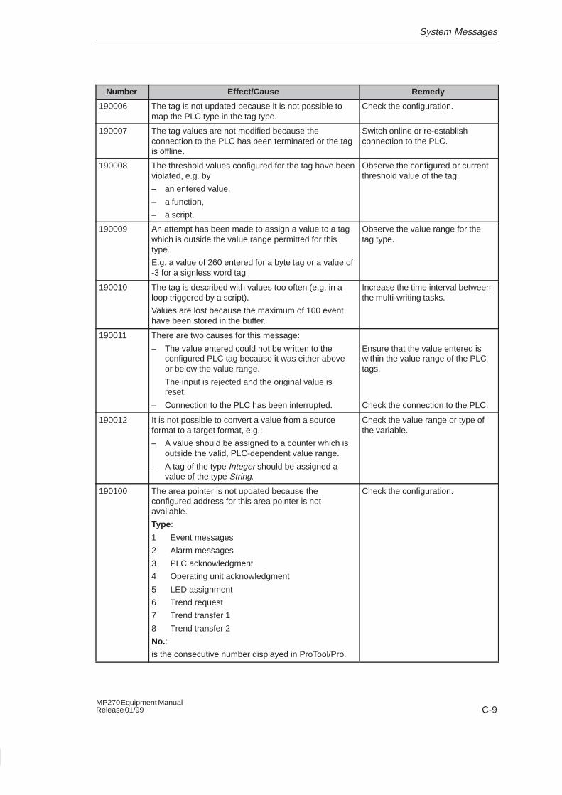
System Messages
C-9MP270 Equipment ManualRelease 01/99
RemedyEffect/CauseNumber
190006 The tag is not updated because it is not possible tomap the PLC type in the tag type.
Check the configuration.
190007 The tag values are not modified because theconnection to the PLC has been terminated or the tagis offline.
Switch online or re-establishconnection to the PLC.
190008 The threshold values configured for the tag have beenviolated, e.g. by
– an entered value,
– a function,
– a script.
Observe the configured or currentthreshold value of the tag.
190009 An attempt has been made to assign a value to a tagwhich is outside the value range permitted for thistype.
E.g. a value of 260 entered for a byte tag or a value of-3 for a signless word tag.
Observe the value range for thetag type.
190010 The tag is described with values too often (e.g. in aloop triggered by a script).
Values are lost because the maximum of 100 eventhave been stored in the buffer.
Increase the time interval betweenthe multi-writing tasks.
190011 There are two causes for this message:
– The value entered could not be written to theconfigured PLC tag because it was either aboveor below the value range.
The input is rejected and the original value isreset.
– Connection to the PLC has been interrupted.
Ensure that the value entered iswithin the value range of the PLCtags.
Check the connection to the PLC.
190012 It is not possible to convert a value from a sourceformat to a target format, e.g.:
– A value should be assigned to a counter which isoutside the valid, PLC-dependent value range.
– A tag of the type Integer should be assigned avalue of the type String.
Check the value range or type ofthe variable.
190100 The area pointer is not updated because theconfigured address for this area pointer is notavailable.
Type :
1 Event messages
2 Alarm messages
3 PLC acknowledgment
4 Operating unit acknowledgment
5 LED assignment
6 Trend request
7 Trend transfer 1
8 Trend transfer 2
No.:
is the consecutive number displayed in ProTool/Pro.
Check the configuration.
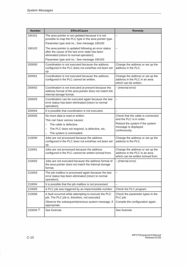
System Messages
C-10MP270 Equipment Manual
Release 01/99
RemedyEffect/CauseNumber
190101 The area pointer is not updated because it is notpossible to map the PLC type in the area pointer type.
Parameter type and no.: See message 190100
–
190102 The area pointer is updated following an error statusafter the cause of the last error state has beeneliminated (return to normal operation).
Parameter type and no.: See message 190100
–
200000 Coordination is not executed because the addressconfigured in the PLC does not exist/has not been setup.
Change the address or set up theaddress in the PLC.
200001 Coordination is not executed because the addressconfigured in the PLC cannot be written.
Change the address or set up theaddress in the PLC in an areawhich can be written.
200002 Coordination is not executed at present because theaddress format of the area pointer does not match theinternal storage format.
– (Internal error)
200003 Coordination can be executed again because the lasterror status has been eliminated (return to normaloperation).
–
200004 It is possible that coordination is not executed. –
200005 No more data is read or written.
This can have various causes:
– The cable is defective.
– The PLC does not respond, is defective, etc.
– The system is overloaded.
Check that the cable is connectedand the PLC is in order.
Reboot the system if the systemmessage is displayedcontinuously.
210000 Jobs are not processed because the addressconfigured in the PLC does not exist/has not been setup.
Change the address or set up theaddress in the PLC.
210001 Jobs are not processed because the addressconfigured in the PLC cannot be written to/read from.
Change the address or set up theaddress in the PLC in an areawhich can be written to/read from.
210002 Jobs are not executed because the address format ofthe area pointer does not match the internal storageformat.
– (Internal error)
210003 The job mailbox is processed again because the lasterror status has been eliminated (return to normaloperation).
–
210004 It is possible that the job mailbox is not processed. –
210005 A PLC job was triggered by an impermissible number. Check the PLC program.
210006 A fault occurred while attempting to execute the PLCjob. The PLC job is, therefore, not executed.
Observe the subsequent/previous system message, ifappropriate.
Check the parameter types in thePLC job.
Compile the configuration again.
220000 2) See footnote See footnote
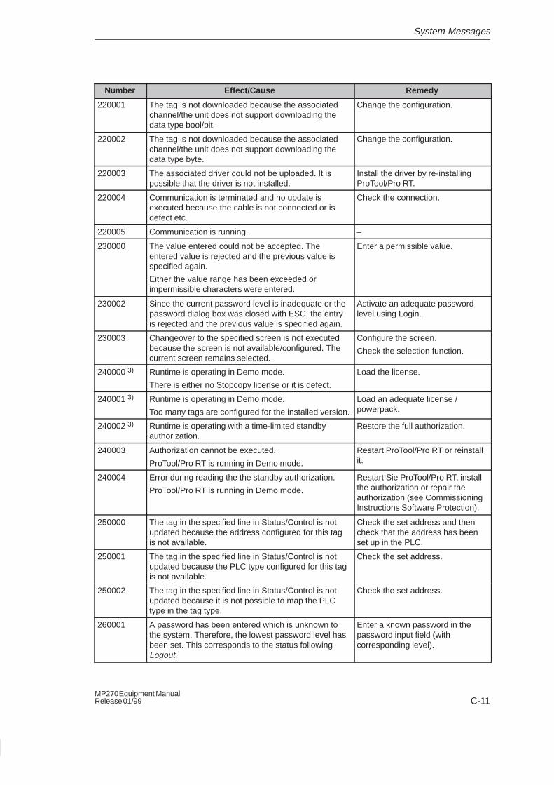
System Messages
C-11MP270 Equipment ManualRelease 01/99
RemedyEffect/CauseNumber
220001 The tag is not downloaded because the associatedchannel/the unit does not support downloading thedata type bool/bit.
Change the configuration.
220002 The tag is not downloaded because the associatedchannel/the unit does not support downloading thedata type byte.
Change the configuration.
220003 The associated driver could not be uploaded. It ispossible that the driver is not installed.
Install the driver by re-installingProTool/Pro RT.
220004 Communication is terminated and no update isexecuted because the cable is not connected or isdefect etc.
Check the connection.
220005 Communication is running. –
230000 The value entered could not be accepted. Theentered value is rejected and the previous value isspecified again.
Either the value range has been exceeded orimpermissible characters were entered.
Enter a permissible value.
230002 Since the current password level is inadequate or thepassword dialog box was closed with ESC, the entryis rejected and the previous value is specified again.
Activate an adequate passwordlevel using Login.
230003 Changeover to the specified screen is not executedbecause the screen is not available/configured. Thecurrent screen remains selected.
Configure the screen.
Check the selection function.
240000 3) Runtime is operating in Demo mode.
There is either no Stopcopy license or it is defect.
Load the license.
240001 3) Runtime is operating in Demo mode.
Too many tags are configured for the installed version.
Load an adequate license /powerpack.
240002 3) Runtime is operating with a time-limited standbyauthorization.
Restore the full authorization.
240003 Authorization cannot be executed.
ProTool/Pro RT is running in Demo mode.
Restart ProTool/Pro RT or reinstallit.
240004 Error during reading the the standby authorization.
ProTool/Pro RT is running in Demo mode.
Restart Sie ProTool/Pro RT, installthe authorization or repair theauthorization (see CommissioningInstructions Software Protection).
250000 The tag in the specified line in Status/Control is notupdated because the address configured for this tagis not available.
Check the set address and thencheck that the address has beenset up in the PLC.
250001 The tag in the specified line in Status/Control is notupdated because the PLC type configured for this tagis not available.
Check the set address.
250002 The tag in the specified line in Status/Control is notupdated because it is not possible to map the PLCtype in the tag type.
Check the set address.
260001 A password has been entered which is unknown tothe system. Therefore, the lowest password level hasbeen set. This corresponds to the status followingLogout.
Enter a known password in thepassword input field (withcorresponding level).
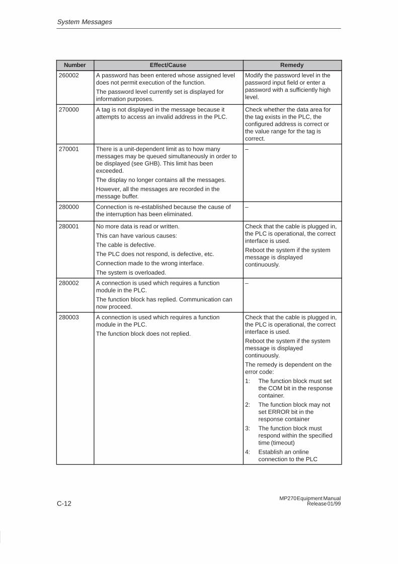
System Messages
C-12MP270 Equipment Manual
Release 01/99
RemedyEffect/CauseNumber
260002 A password has been entered whose assigned leveldoes not permit execution of the function.
The password level currently set is displayed forinformation purposes.
Modify the password level in thepassword input field or enter apassword with a sufficiently highlevel.
270000 A tag is not displayed in the message because itattempts to access an invalid address in the PLC.
Check whether the data area forthe tag exists in the PLC, theconfigured address is correct orthe value range for the tag iscorrect.
270001 There is a unit-dependent limit as to how manymessages may be queued simultaneously in order tobe displayed (see GHB). This limit has beenexceeded.
The display no longer contains all the messages.
However, all the messages are recorded in themessage buffer.
–
280000 Connection is re-established because the cause ofthe interruption has been eliminated.
–
280001 No more data is read or written.
This can have various causes:
The cable is defective.
The PLC does not respond, is defective, etc.
Connection made to the wrong interface.
The system is overloaded.
Check that the cable is plugged in,the PLC is operational, the correctinterface is used.
Reboot the system if the systemmessage is displayedcontinuously.
280002 A connection is used which requires a functionmodule in the PLC.
The function block has replied. Communication cannow proceed.
–
280003 A connection is used which requires a functionmodule in the PLC.
The function block does not replied.
Check that the cable is plugged in,the PLC is operational, the correctinterface is used.
Reboot the system if the systemmessage is displayedcontinuously.
The remedy is dependent on theerror code:
1: The function block must setthe COM bit in the responsecontainer.
2: The function block may notset ERROR bit in theresponse container
3: The function block mustrespond within the specifiedtime (timeout)
4: Establish an onlineconnection to the PLC
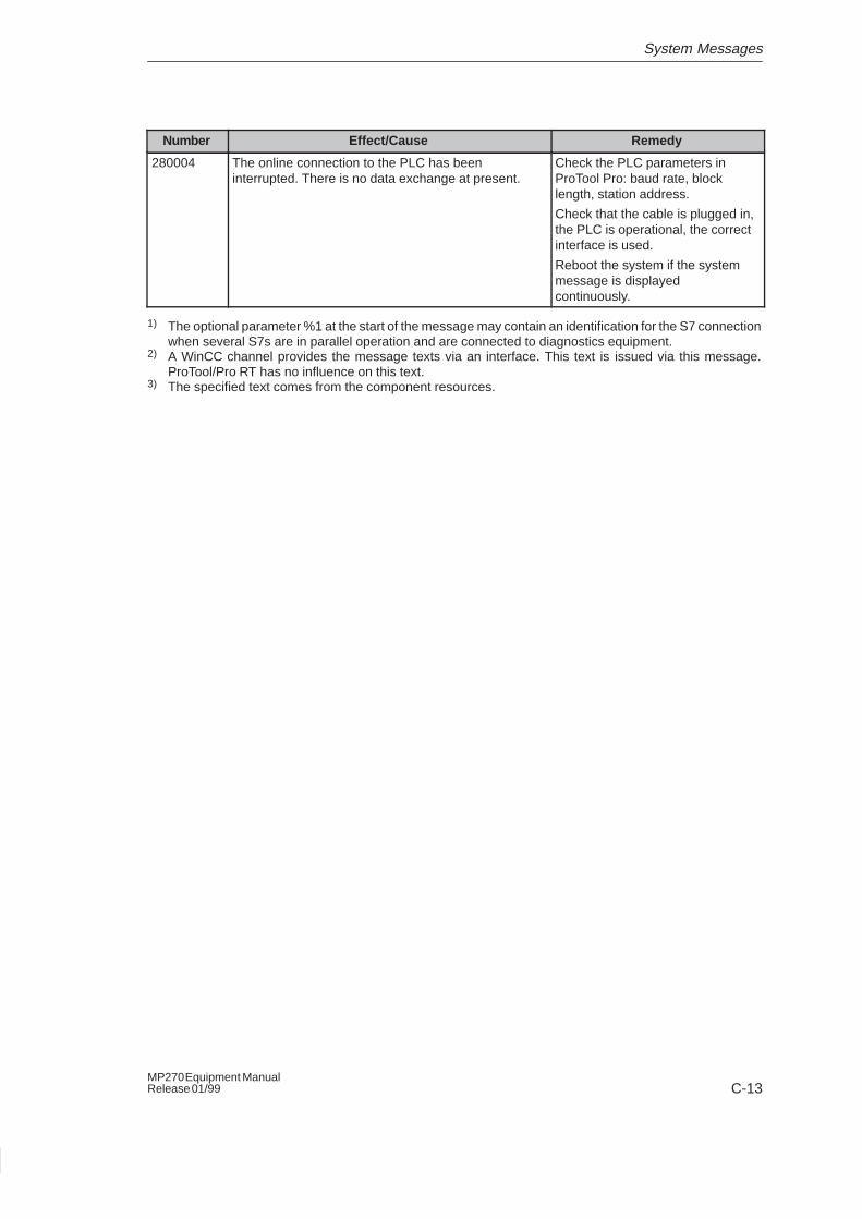
System Messages
C-13MP270 Equipment ManualRelease 01/99
RemedyEffect/CauseNumber
280004 The online connection to the PLC has beeninterrupted. There is no data exchange at present.
Check the PLC parameters inProTool Pro: baud rate, blocklength, station address.
Check that the cable is plugged in,the PLC is operational, the correctinterface is used.
Reboot the system if the systemmessage is displayedcontinuously.
1) The optional parameter %1 at the start of the message may contain an identification for the S7 connectionwhen several S7s are in parallel operation and are connected to diagnostics equipment.
2) A WinCC channel provides the message texts via an interface. This text is issued via this message.ProTool/Pro RT has no influence on this text.
3) The specified text comes from the component resources.

System Messages
C-14MP270 Equipment Manual
Release 01/99
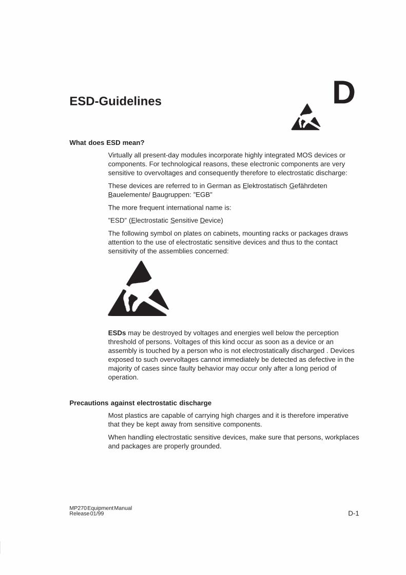
D-1MP270 Equipment ManualRelease 01/99
ESD-Guidelines
What does ESD mean?
Virtually all present-day modules incorporate highly integrated MOS devices orcomponents. For technological reasons, these electronic components are verysensitive to overvoltages and consequently therefore to electrostatic discharge:
These devices are referred to in German as Elektrostatisch GefährdetenBauelemente/ Baugruppen: ”EGB”
The more frequent international name is:
”ESD” (Electrostatic Sensitive Device)
The following symbol on plates on cabinets, mounting racks or packages drawsattention to the use of electrostatic sensitive devices and thus to the contactsensitivity of the assemblies concerned:
ESDs may be destroyed by voltages and energies well below the perceptionthreshold of persons. Voltages of this kind occur as soon as a device or anassembly is touched by a person who is not electrostatically discharged . Devicesexposed to such overvoltages cannot immediately be detected as defective in themajority of cases since faulty behavior may occur only after a long period ofoperation.
Precautions against electrostatic discharge
Most plastics are capable of carrying high charges and it is therefore imperativethat they be kept away from sensitive components.
When handling electrostatic sensitive devices, make sure that persons, workplacesand packages are properly grounded.
D
ESD-Guidelines
D-2MP270 Equipment Manual
Release 01/99
Handling ESD assemblies
A general rule is that assemblies should be touched only when this cannot beavoided owing to the work that has to performed on them. Under no circumstancesshould you handle printed-circuit boards by touching device pins or circuitry.
You should touch devices only if
� you are grounded by permanently wearing an ESD wrist strap or
� you are wearing ESD shoes or ESD shoe-grounding protection straps inconjunction with an ESD floor.
Before you touch an electronic assembly, your body must be discharged. Thesimplest way of doing this is to touch a conductive, grounded object immediatelybeforehand – for example, bare metal parts of a cabinet, water pipe etc.
Assemblies should not be brought into contact with charge-susceptible and highlyinsulating materials such as plastic films, insulating table tops and items of clothingetc. containing synthetic fibers.
Assemblies should be deposited only on conductive surfaces (tables with an ESDcoating, conductive ESD cellular material, ESD bags, ESD shipping containers).
Do not place assemblies near visual display units, monitors or television sets(minimum distance to screen > 10 cm).
Measuring and modifying ESD assemblies
Perform measurements on ESD assemblies only when
� the measuring instrument is grounded – for example, by means of a protectiveconductor – or
� the measuring head has been briefly discharged before measurements aremade with a potential-free measuring instrument – for example, by touching abare metal control cabinet.
When soldering, use only grounded soldering irons.
Shipping ESD assemblies
Always store and ship assemblies and devices in conductive packing – forexample, metallized plastic boxes and tin cans.
If packing is not conductive, assemblies must be conductively wrapped before theyare packed. You can use, for example, conductive foam rubber, ESD bags,domestic aluminum foil or paper (never use plastic bags or foils).
With assemblies containing fitted batteries, make sure that the conductive packingdoes not come into contact with or short-circuit battery connectors. If necessary,cover the connectors beforehand with insulating tape or insulating material.
E-1MP270 Equipment ManualRelease 01/99
SIMATIC HMI Documentation
Target groups
This manual is part of the SIMATIC HMI documentation. The documentation isaimed at the following target groups:
� Newcomers
� Users
� Configurers
� Programmers
� Commissioning engineers
How the documentation is organized
The SIMATIC HMI documentation consists of the following components:
� User’s Guides / User’s Manuals for:
– Configuration software
– Runtime software
– Communication between PLCs and operating units
� Equipment Manuals for the following operating units:
– MP (Multi Panel)
– OP (Operator Panel)
– TP (Touch Panel)
– TD (Text Display)
– PP (Push Button Panel)
� Online Help on the configuration software
� Start–up Guides
� First Steps
Overview of complete documentation
The following table provides an overview of the SIMATIC HMI documentation andshows you when you require the different documents.
E
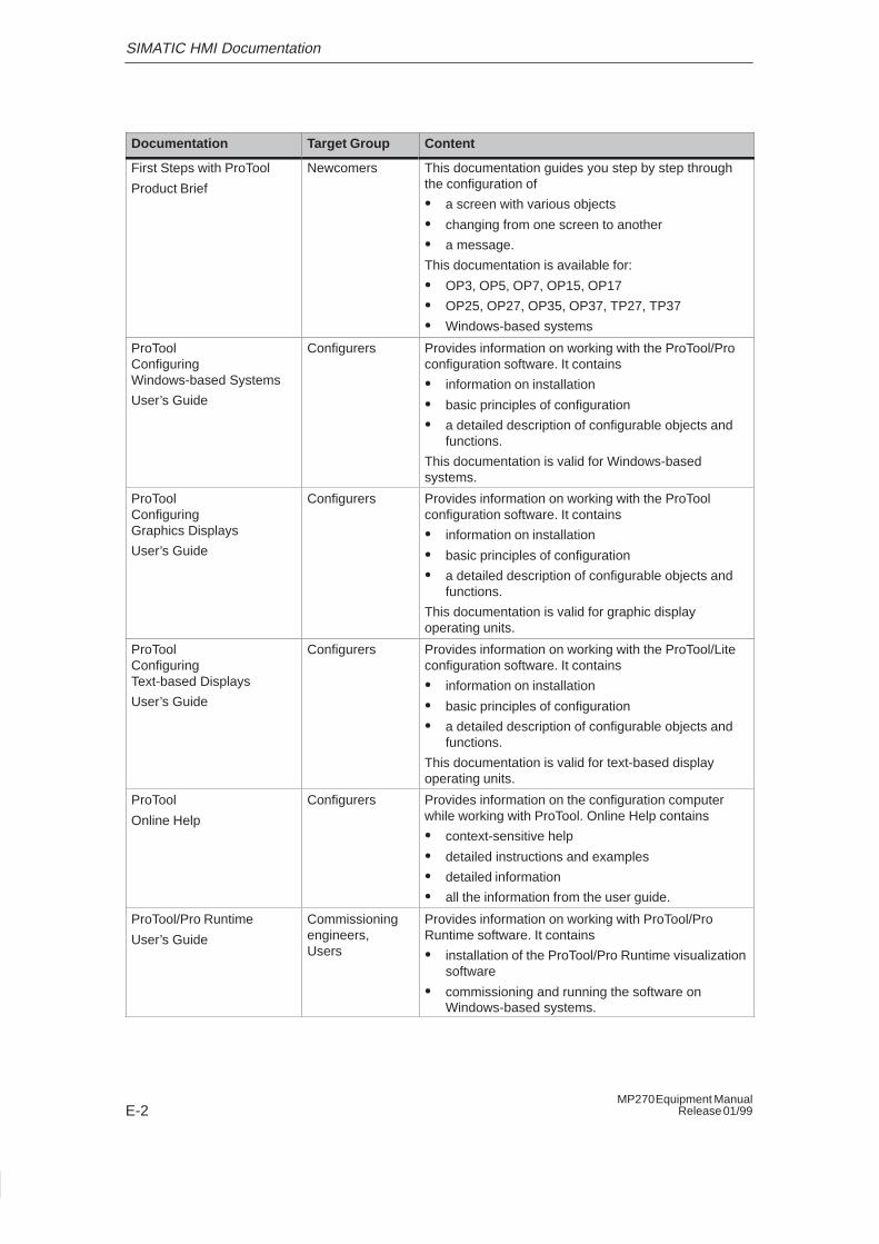
SIMATIC HMI Documentation
E-2MP270 Equipment Manual
Release 01/99
Documentation Target Group Content
First Steps with ProTool
Product Brief
Newcomers This documentation guides you step by step throughthe configuration of
� a screen with various objects
� changing from one screen to another
� a message.
This documentation is available for:
� OP3, OP5, OP7, OP15, OP17
� OP25, OP27, OP35, OP37, TP27, TP37
� Windows-based systems
ProToolConfiguring Windows-based Systems
User’s Guide
Configurers Provides information on working with the ProTool/Proconfiguration software. It contains
� information on installation
� basic principles of configuration
� a detailed description of configurable objects andfunctions.
This documentation is valid for Windows-basedsystems.
ProToolConfiguring Graphics Displays
User’s Guide
Configurers Provides information on working with the ProToolconfiguration software. It contains
� information on installation
� basic principles of configuration
� a detailed description of configurable objects andfunctions.
This documentation is valid for graphic displayoperating units.
ProToolConfiguring Text-based Displays
User’s Guide
Configurers Provides information on working with the ProTool/Liteconfiguration software. It contains
� information on installation
� basic principles of configuration
� a detailed description of configurable objects andfunctions.
This documentation is valid for text-based displayoperating units.
ProTool
Online Help
Configurers Provides information on the configuration computerwhile working with ProTool. Online Help contains
� context-sensitive help
� detailed instructions and examples
� detailed information
� all the information from the user guide.
ProTool/Pro Runtime
User’s Guide
Commissioningengineers, Users
Provides information on working with ProTool/ProRuntime software. It contains
� installation of the ProTool/Pro Runtime visualizationsoftware
� commissioning and running the software onWindows-based systems.
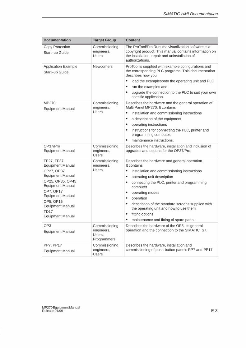
SIMATIC HMI Documentation
E-3MP270 Equipment ManualRelease 01/99
ContentTarget GroupDocumentation
Copy Protection
Start–up Guide
Commissioningengineers, Users
The ProTool/Pro Runtime visualization software is acopyright product. This manual contains information onthe installation, repair and uninstallation ofauthorizations.
Application Example
Start–up Guide
Newcomers ProTool is supplied with example configurations andthe corresponding PLC programs. This documentationdescribes how you
� load the examplesonto the operating unit and PLC
� run the examples and
� upgrade the connection to the PLC to suit your ownspecific application.
MP270
Equipment Manual
Commissioningengineers, Users
Describes the hardware and the general operation ofMulti Panel MP270. It contains
� installation and commissioning instructions
� a description of the equipment
� operating instructions
� instructions for connecting the PLC, printer andprogramming computer,
� maintenance instructions.
OP37/ProEquipment Manual
Commissioningengineers, Users
Describes the hardware, installation and inclusion ofupgrades and options for the OP37/Pro.
TP27, TP37Equipment Manual
OP27, OP37Equipment Manual
OP25, OP35, OP45Equipment Manual
OP7, OP17Equipment Manual
OP5, OP15Equipment Manual
TD17Equipment Manual
Commissioningengineers, Users
Describes the hardware and general operation. It contains
� installation and commissioning instructions
� operating unit description
� connecting the PLC, printer and programmingcomputer
� operating modes
� operation
� description of the standard screens supplied withthe operating unit and how to use them
� fitting options
� maintenance and fitting of spare parts.
OP3
Equipment Manual
Commissioningengineers, Users, Programmers
Describes the hardware of the OP3, its generaloperation and the connection to the SIMATIC S7.
PP7, PP17
Equipment Manual
Commissioningengineers, Users
Describes the hardware, installation andcommissioning of push-button panels PP7 and PP17.
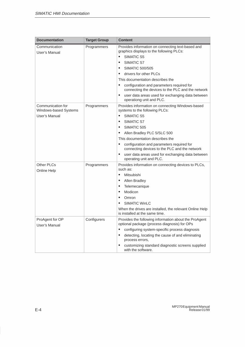
SIMATIC HMI Documentation
E-4MP270 Equipment Manual
Release 01/99
ContentTarget GroupDocumentation
Communication
User’s Manual
Programmers Provides information on connecting text-based andgraphics displays to the following PLCs:
� SIMATIC S5
� SIMATIC S7
� SIMATIC 500/505
� drivers for other PLCs
This documentation describes the
� configuration and parameters required forconnecting the devices to the PLC and the network
� user data areas used for exchanging data betweenoperationg unit and PLC.
Communication for Windows-based Systems
User’s Manual
Programmers Provides information on connecting Windows-basedsystems to the following PLCs:
� SIMATIC S5
� SIMATIC S7
� SIMATIC 505
� Allen Bradley PLC 5/SLC 500
This documentation describes the
� configuration and parameters required forconnecting devices to the PLC and the network
� user data areas used for exchanging data betweenoperating unit and PLC.
Other PLCs
Online Help
Programmers Provides information on connecting devices to PLCs,such as:
� Mitsubishi
� Allen Bradley
� Telemecanique
� Modicon
� Omron
� SIMATIC WinLC
When the drives are installed, the relevant Online Helpis installed at the same time.
ProAgent for OP
User’s Manual
Configurers Provides the following information about the ProAgentoptional package (process diagnosis) for OPs
� configuring system-specific process diagnosis
� detecting, locating the cause of and eliminatingprocess errors,
� customizing standard diagnostic screens suppliedwith the software.
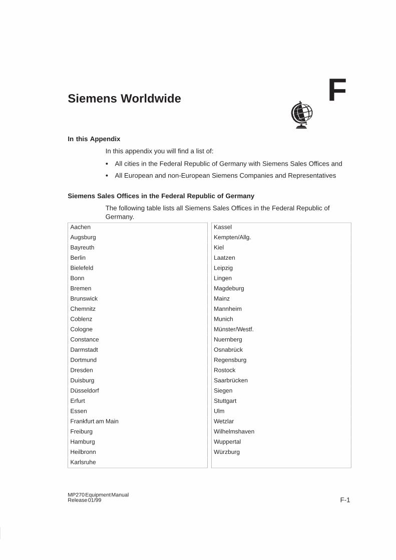
F-1MP270 Equipment ManualRelease 01/99
Siemens Worldwide
In this Appendix
In this appendix you will find a list of:
� All cities in the Federal Republic of Germany with Siemens Sales Offices and
� All European and non-European Siemens Companies and Representatives
Siemens Sales Offices in the Federal Republic of Germany
The following table lists all Siemens Sales Offices in the Federal Republic ofGermany.
Aachen
Augsburg
Bayreuth
Berlin
Bielefeld
Bonn
Bremen
Brunswick
Chemnitz
Coblenz
Cologne
Constance
Darmstadt
Dortmund
Dresden
Duisburg
Düsseldorf
Erfurt
Essen
Frankfurt am Main
Freiburg
Hamburg
Heilbronn
Karlsruhe
Kassel
Kempten/Allg.
Kiel
Laatzen
Leipzig
Lingen
Magdeburg
Mainz
Mannheim
Munich
Münster/Westf.
Nuernberg
Osnabrück
Regensburg
Rostock
Saarbrücken
Siegen
Stuttgart
Ulm
Wetzlar
Wilhelmshaven
Wuppertal
Würzburg
F
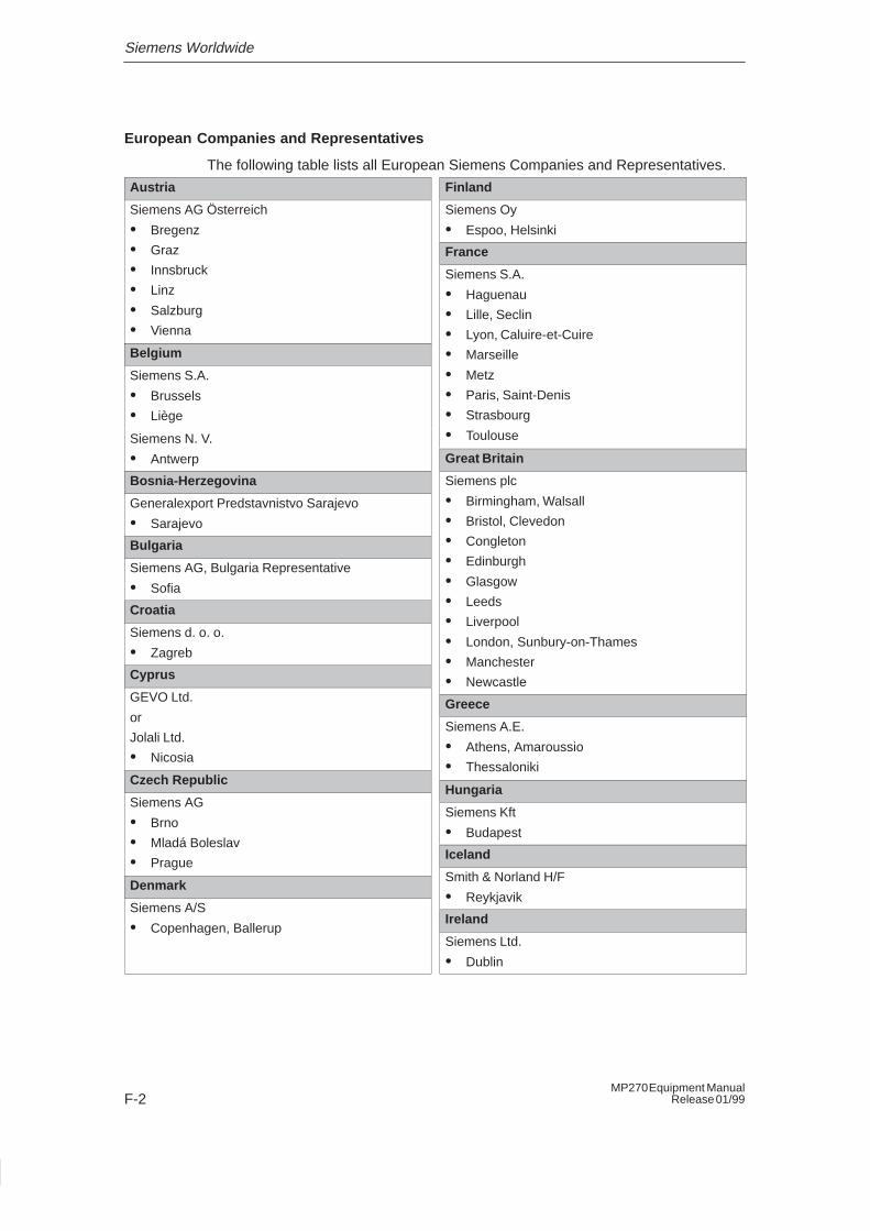
Siemens Worldwide
F-2MP270 Equipment Manual
Release 01/99
European Companies and Representatives
The following table lists all European Siemens Companies and Representatives.
Austria
Siemens AG Österreich
� Bregenz
� Graz
� Innsbruck
� Linz
� Salzburg
� Vienna
Belgium
Siemens S.A.
� Brussels
� Liège
Siemens N. V.
� Antwerp
Bosnia-Herzegovina
Generalexport Predstavnistvo Sarajevo
� Sarajevo
Bulgaria
Siemens AG, Bulgaria Representative
� Sofia
Croatia
Siemens d. o. o.
� Zagreb
Cyprus
GEVO Ltd.
or
Jolali Ltd.
� Nicosia
Czech Republic
Siemens AG
� Brno
� Mladá Boleslav
� Prague
Denmark
Siemens A/S
� Copenhagen, Ballerup
Finland
Siemens Oy
� Espoo, Helsinki
France
Siemens S.A.
� Haguenau
� Lille, Seclin
� Lyon, Caluire-et-Cuire
� Marseille
� Metz
� Paris, Saint-Denis
� Strasbourg
� Toulouse
Great Britain
Siemens plc
� Birmingham, Walsall
� Bristol, Clevedon
� Congleton
� Edinburgh
� Glasgow
� Leeds
� Liverpool
� London, Sunbury-on-Thames
� Manchester
� Newcastle
Greece
Siemens A.E.
� Athens, Amaroussio
� Thessaloniki
Hungaria
Siemens Kft
� Budapest
Iceland
Smith & Norland H/F
� Reykjavik
Ireland
Siemens Ltd.
� Dublin
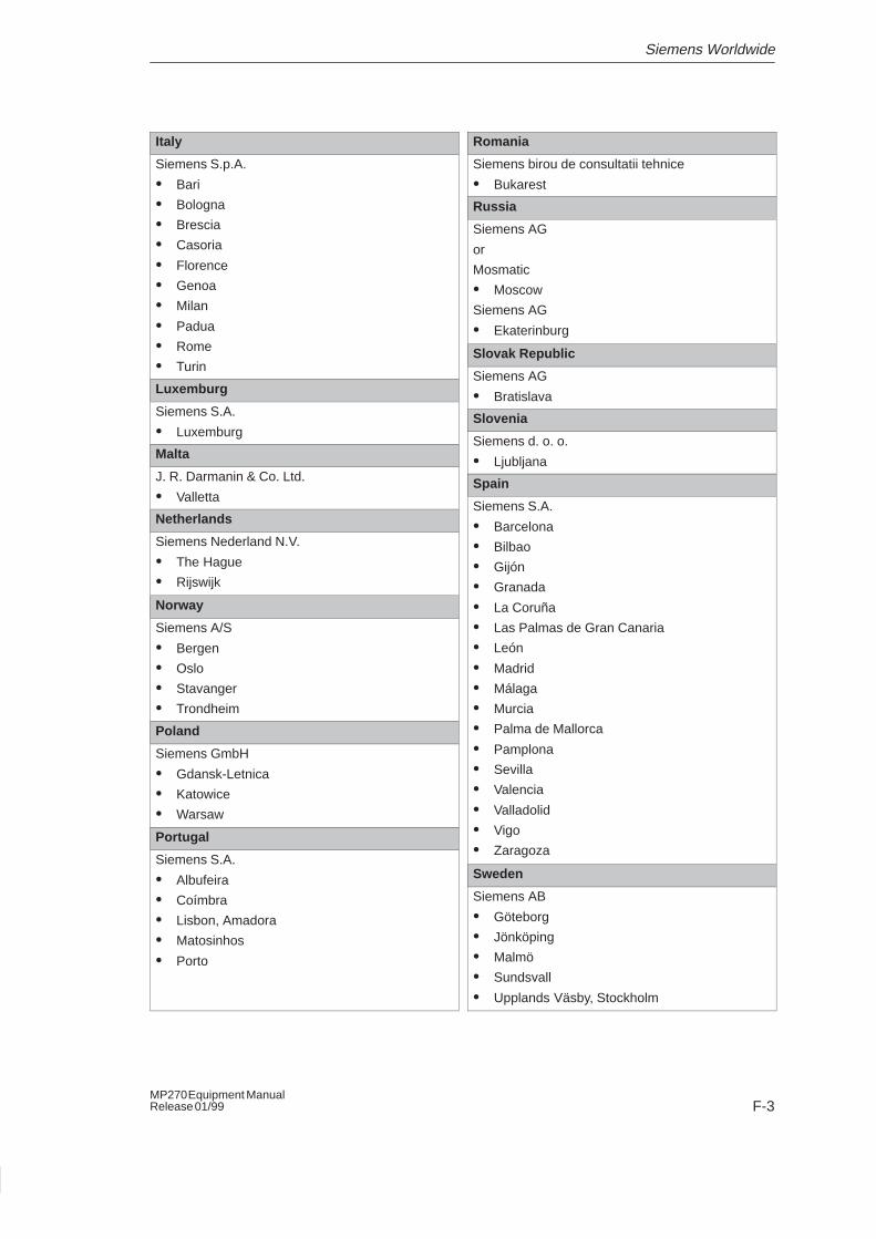
Siemens Worldwide
F-3MP270 Equipment ManualRelease 01/99
Italy
Siemens S.p.A.
� Bari
� Bologna
� Brescia
� Casoria
� Florence
� Genoa
� Milan
� Padua
� Rome
� Turin
Luxemburg
Siemens S.A.
� Luxemburg
Malta
J. R. Darmanin & Co. Ltd.
� Valletta
Netherlands
Siemens Nederland N.V.
� The Hague
� Rijswijk
Norway
Siemens A/S
� Bergen
� Oslo
� Stavanger
� Trondheim
Poland
Siemens GmbH
� Gdansk-Letnica
� Katowice
� Warsaw
Portugal
Siemens S.A.
� Albufeira
� Coímbra
� Lisbon, Amadora
� Matosinhos
� Porto
Romania
Siemens birou de consultatii tehnice
� Bukarest
Russia
Siemens AG
or
Mosmatic
� Moscow
Siemens AG
� Ekaterinburg
Slovak Republic
Siemens AG
� Bratislava
Slovenia
Siemens d. o. o.
� Ljubljana
Spain
Siemens S.A.
� Barcelona
� Bilbao
� Gijón
� Granada
� La Coruña
� Las Palmas de Gran Canaria
� León
� Madrid
� Málaga
� Murcia
� Palma de Mallorca
� Pamplona
� Sevilla
� Valencia
� Valladolid
� Vigo
� Zaragoza
Sweden
Siemens AB
� Göteborg
� Jönköping
� Malmö
� Sundsvall
� Upplands Väsby, Stockholm
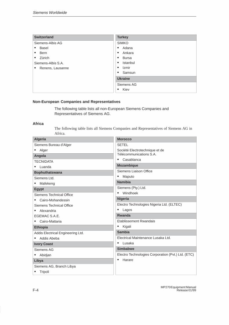
Siemens Worldwide
F-4MP270 Equipment Manual
Release 01/99
Switzerland
Siemens-Albis AG� Basel� Bern� Zürich
Siemens-Albis S.A.� Renens, Lausanne
Turkey
SIMKO� Adana� Ankara� Bursa� Istanbul� Izmir� Samsun
Ukraine
Siemens AG� Kiev
Non-European Companies and Representatives
The following table lists all non-European Siemens Companies andRepresentatives of Siemens AG.
AfricaThe following table lists all Siemens Companies and Representatives of Siemens AG inAfrica.
Algeria
Siemens Bureau d’Alger
� Alger
Angola
TECNIDATA
� Luanda
Bophuthatswana
Siemens Ltd.
� Mafekeng
Egypt
Siemens Technical Office
� Cairo-Mohandessin
Siemens Technical Office
� Alexandria
EGEMAC S.A.E.
� Cairo-Mattaria
Ethiopia
Addis Electrical Engineering Ltd.
� Addis Abeba
Ivory Coast
Siemens AG
� Abidjan
Libya
Siemens AG, Branch Libya
� Tripoli
Morocco
SETEL
Société Electrotechnique et deTélécommunications S.A.
� Casablanca
Mozambique
Siemens Liaison Office
� Maputo
Namibia
Siemens (Pty.) Ltd.
� Windhoek
Nigeria
Electro Technologies Nigeria Ltd. (ELTEC)
� Lagos
Rwanda
Etablissement Rwandais
� Kigali
Sambia
Electrical Maintenance Lusaka Ltd.
� Lusaka
Simbabwe
Electro Technologies Corporation (Pvt.) Ltd. (ETC)
� Harare
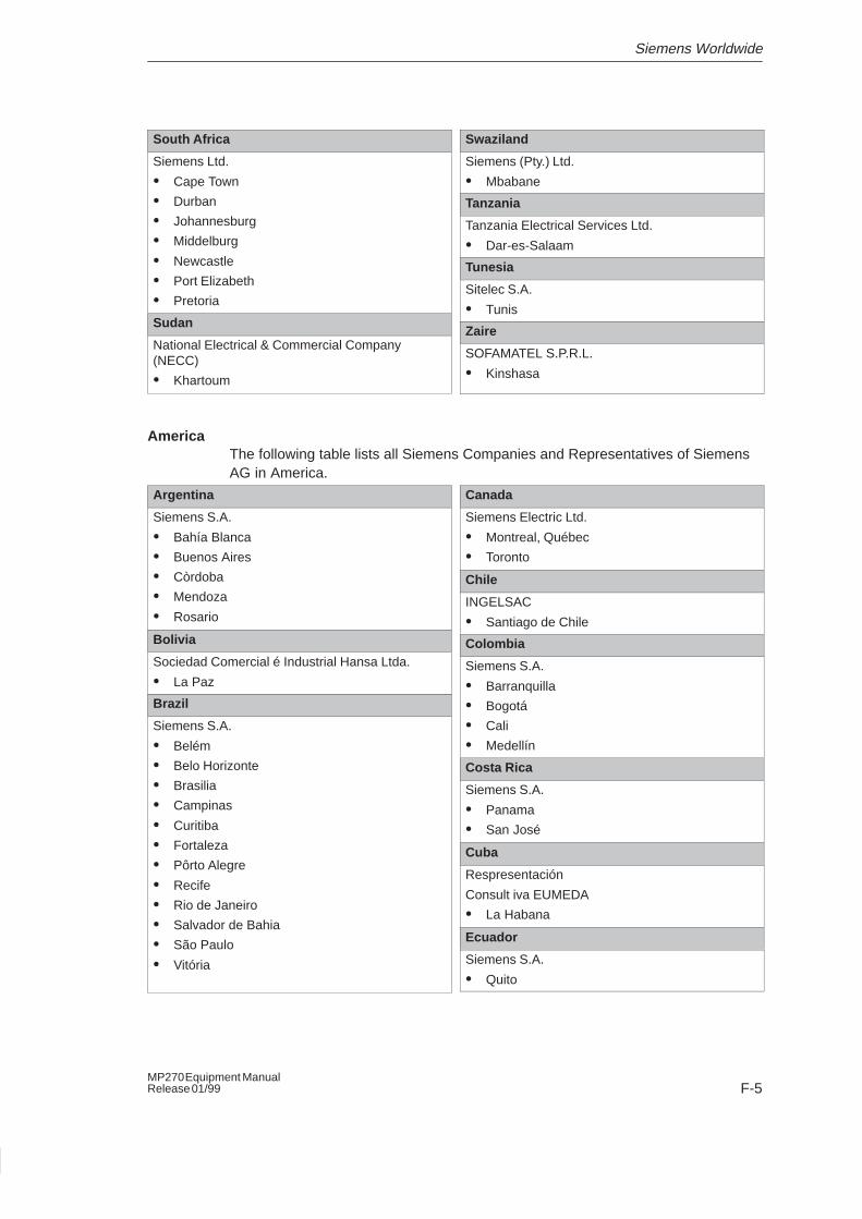
Siemens Worldwide
F-5MP270 Equipment ManualRelease 01/99
South Africa
Siemens Ltd.
� Cape Town
� Durban
� Johannesburg
� Middelburg
� Newcastle
� Port Elizabeth
� Pretoria
Sudan
National Electrical & Commercial Company(NECC)
� Khartoum
Swaziland
Siemens (Pty.) Ltd.
� Mbabane
Tanzania
Tanzania Electrical Services Ltd.
� Dar-es-Salaam
Tunesia
Sitelec S.A.
� Tunis
Zaire
SOFAMATEL S.P.R.L.
� Kinshasa
AmericaThe following table lists all Siemens Companies and Representatives of SiemensAG in America.
Argentina
Siemens S.A.
� Bahía Blanca
� Buenos Aires
� Còrdoba
� Mendoza
� Rosario
Bolivia
Sociedad Comercial é Industrial Hansa Ltda.
� La Paz
Brazil
Siemens S.A.
� Belém
� Belo Horizonte
� Brasilia
� Campinas
� Curitiba
� Fortaleza
� Pôrto Alegre
� Recife
� Rio de Janeiro
� Salvador de Bahia
� São Paulo
� Vitória
Canada
Siemens Electric Ltd.
� Montreal, Québec
� Toronto
Chile
INGELSAC
� Santiago de Chile
Colombia
Siemens S.A.
� Barranquilla
� Bogotá
� Cali
� Medellín
Costa Rica
Siemens S.A.
� Panama
� San José
Cuba
Respresentación
Consult iva EUMEDA
� La Habana
Ecuador
Siemens S.A.
� Quito
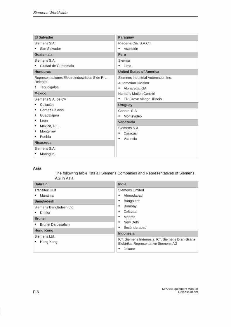
Siemens Worldwide
F-6MP270 Equipment Manual
Release 01/99
El Salvador
Siemens S.A.
� San Salvador
Guatemala
Siemens S.A.
� Ciudad de Guatemala
Honduras
Representaciones Electroindustriales S de R.L. -Relectro
� Tegucigalpa
Mexico
Siemens S.A. de CV
� Culiacán
� Gómez Palacio
� Guadalajara
� León
� México, D.F.
� Monterrey
� Puebla
Nicaragua
Siemens S.A.
� Managua
Paraguay
Rieder & Cia. S.A.C.I.
� Asunción
Peru
Siemsa
� Lima
United States of America
Siemens Industrial Automation Inc.
Automation Division
� Alpharetta, GA
Numeric Motion Control
� Elk Grove Village, Illinois
Uruguay
Conatel S.A.
� Montevideo
Venezuela
Siemens S.A.
� Caracas
� Valencia
AsiaThe following table lists all Siemens Companies and Representatives of SiemensAG in Asia.
Bahrain
Transitec Gulf
� Manama
Bangladesh
Siemens Bangladesh Ltd.
� Dhaka
Brunei
� Brunei Darussalam
Hong Kong
Siemens Ltd.
� Hong Kong
India
Siemens Limited
� Ahmedabad
� Bangalore
� Bombay
� Calcutta
� Madras
� New Delhi
� Secúnderabad
Indonesia
P.T. Siemens Indonesia, P.T. Siemens Dian-GranaElektrika, Representative Siemens AG
� Jakarta
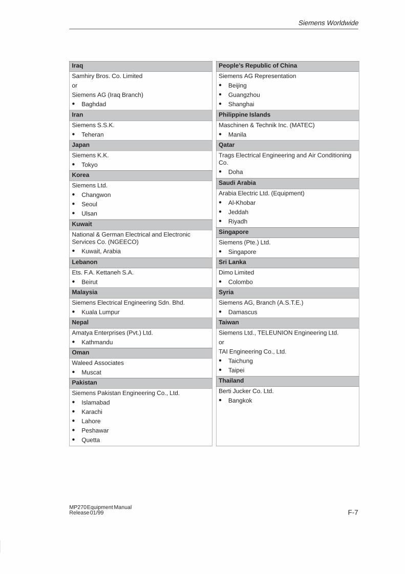
Siemens Worldwide
F-7MP270 Equipment ManualRelease 01/99
Iraq
Samhiry Bros. Co. Limited
or
Siemens AG (Iraq Branch)
� Baghdad
Iran
Siemens S.S.K.
� Teheran
Japan
Siemens K.K.
� Tokyo
Korea
Siemens Ltd.
� Changwon
� Seoul
� Ulsan
Kuwait
National & German Electrical and ElectronicServices Co. (NGEECO)
� Kuwait, Arabia
Lebanon
Ets. F.A. Kettaneh S.A.
� Beirut
Malaysia
Siemens Electrical Engineering Sdn. Bhd.
� Kuala Lumpur
Nepal
Amatya Enterprises (Pvt.) Ltd.
� Kathmandu
Oman
Waleed Associates
� Muscat
Pakistan
Siemens Pakistan Engineering Co., Ltd.
� Islamabad
� Karachi
� Lahore
� Peshawar
� Quetta
People’s Republic of China
Siemens AG Representation
� Beijing
� Guangzhou
� Shanghai
Philippine Islands
Maschinen & Technik Inc. (MATEC)
� Manila
Qatar
Trags Electrical Engineering and Air ConditioningCo.
� Doha
Saudi Arabia
Arabia Electric Ltd. (Equipment)
� Al-Khobar
� Jeddah
� Riyadh
Singapore
Siemens (Pte.) Ltd.
� Singapore
Sri Lanka
Dimo Limited
� Colombo
Syria
Siemens AG, Branch (A.S.T.E.)
� Damascus
Taiwan
Siemens Ltd., TELEUNION Engineering Ltd.
or
TAI Engineering Co., Ltd.
� Taichung
� Taipei
Thailand
Berti Jucker Co. Ltd.
� Bangkok
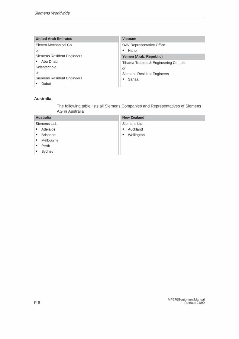
Siemens Worldwide
F-8MP270 Equipment Manual
Release 01/99
United Arab Emirates
Electro Mechanical Co.
or
Siemens Resident Engineers
� Abu Dhabi
Scientechnic
or
Siemens Resident Engineers
� Dubai
Vietnam
OAV Representative Office
� Hanoi
Yemen (Arab. Republic)
Tihama Tractors & Engineering Co., Ltd.
or
Siemens Resident Engineers
� Sanaa
Australia
The following table lists all Siemens Companies and Representatives of SiemensAG in Australia
Australia
Siemens Ltd.
� Adelaide
� Brisbane
� Melbourne
� Perth
� Sydney
New Zealand
Siemens Ltd.
� Auckland
� Wellington
Glossary-1MP270 Equipment ManualRelease 01/99
Glossary
Acknowledgement
Acknowledgement of an alarm message on the operating unit confirms that it hasbeen noted. After acknowledgement, the message disappears from the screen.
Alarm message
Provides information on the operating unit concerning operating errors on themachine or system connected to the PLC. The message text may also containcurrent measured values.
Since alarm messages indicate abnormal operating statues, they must beacknowledged.
Alarm time
Time interval between the arrival and departure of an alarm message.
Area pointer
Defines a memory area in the PLC for data exchange between the PLC andoperating unit.
Bar graphs
Represent values from the PLC as rectangular areas. This is a way of displayingfilling levels or workpiece numbers, for example, on the operating unit.
Baud rate
Rate of speed at which data is downloaded. Baud rate is specified in Bit/s.
Glossary
Glossary-2MP270 Equipment Manual
Release 01/99
Blank
Switch off or fade out the screen saver.
Boot
A loading process which downloads the operating system in the working memoryof the operating unit
Configuration
Definition of system–specific default settings, messages and screens using theconfiguration software ProTool .
Download
The transfer of run–capable project data to the operating unit. Connect theoperating unit to the configuration computer with a standard cable beforehand.
Download mode
Operating unit operating mode in which data can be downloaded from theconfiguration computer to the operating unit (also refer to Download ).
Event message
Provides information on the operating unit concerning the operating statuses of themachine or system connected to the PLC. The message text may also containcurrent measured values.
Glossary
Glossary-3MP270 Equipment ManualRelease 01/99
Fixed window
The window which always appears at the top of the operating unit screen. Thecontent of the fixed window is independent of the screen currently open.
Flash memory
Programmable memory which can be electrically deleted and written to againsegment–by–segment.
Function key
Key on the operating unit to which a configurable function can be assigned.
Help text
Configurable, additional information on messages, screens and fields. The helptext concerning an alarm message can, for example, contain information on thecause of the fault and methods of elimination.
Icon
Configured graphic symbol identifying the function of a function key.
Input field
Enables the user to enter values which are subsequently downloaded to the PLC.
Logout time
Configurable interval of time after which the password level is reset to zero whenthe operating unit is not used.
Glossary
Glossary-4MP270 Equipment Manual
Release 01/99
Message arrival
Time at which a message was triggered by the PLC or operating unit.
Message departure
Time at which a message was withdrawn by the PLC.
Message event
Message events consist of:
� Message arrival
� Message acknowledgement
� Message departure
Message indicator
A graphical symbol displayed on the operating unit when at least one alarmmessage is present .
Message logging
Printout of alarm and event messages parallel to their display on the operating unitdisplay.
Multi Panel
Multi–functional, configurable operating unit with graphics display and Windows�CE operating system for operating and monitoring machines and systems.
Normal operation
Operating unit operating mode in which messages are displayed and screens canbe operated.
Glossary
Glossary-5MP270 Equipment ManualRelease 01/99
Operator Panel
Operating unit which can be configured for operating and monitoring machines andsystems.
Output field
Displays current values from the PLC on the operating unit.
Password
A character string which must be entered on the operating unit before a protectedfunction can be activated. Each password is assigned to a password level .
Password level
Defines the user’s rights. The rights are in hierarchical steps from Level 0 (lowestlevel) to Level 9 (highest level). The password level linked to the passwordallocates the rights to execute functions on the operating unit belonging to thatlevel or lower.
PCL
Hewlett� Packard (Printer Control Language).
PCMCIA
Personal Computer Memory Card International Association
Joint operation of computer companies with the aim of defining one internationalstandard for memory cards and PC expansion cards. Cooperation with JEIDA .
PLC
General term for units and systems with which the operating unit communicates(e.g. SIMATIC S7 or PC).
PLC job
PLC jobs can be used by the PLC to trigger functions on the operating unit, e.g.display a screen.
Glossary
Glossary-6MP270 Equipment Manual
Release 01/99
Power–up test
Checks the status of the CPU and memory each time the power is switched on.
Print screen
Printout of a copy of the screen contents.
Process screen
The display of process values and process progress on the operating unit in theform of screens, which may contain graphics, texts and values.
Programmable controller
PLC from the SIMATIC S5 series (e.g. AG S5-115U/135U).
Programmable system
PLC from the SIMATIC S7 series (SIMATIC S7-200/300/400).
ProTool
Full graphics based configuration software for the whole SIMATIC HMI unit rangeand for Windows–based systems.
Remaining buffer
Configurable size of the message buffer. In the case of buffer overflow, theoperating unit deletes message events until the configured remaining buffercapacity is reached.
RS232
Standard interface for serial data transfer at a defined voltage level. Transmitterand receiver are electrically connected.
RS485
Standard interface for serial data transfer at a very high transmission rate.
Glossary
Glossary-7MP270 Equipment ManualRelease 01/99
Runtime software
A program with which your configuration can be run on the MP270 and the processvisualized. The runtime software ProTool/Pro RT can be run on the followingWindows–based systems: MP270, OP37/Pro, Standard PC.
Screen
A screen displays all the logically related process data on the operating unit,whereby the individual values can be modified.
Selection field
Contains a list of entries from which one can be selected on the operating unit.
Softkey
Function key on the operating unit with a local function assignment. The functiontriggered by a softkey varies according to the screen currently open
Start screen
The first screen, which automatically appears after the MP270 has started up.
Status/Force tag
Screen object with which individual address areas in the connected SIMATIC S5 orSIMATIC S7 can be accessed for reading and writing directly from the operatingunit.
Superuser
A user with permissions to trigger functions of the highest password level . Thesuperuser has access to all the operating unit functions.
System message
Provides information on the operating unit concerning internal statuses of theoperating unit and PLC.
Glossary
Glossary-8MP270 Equipment Manual
Release 01/99
Tag
A defined memory location in which values can be read from and written to. Thiscan be performed from the PLC or via the operating unit. Depending on whetherthe tag is linked to the PLC or not, a distinction is made between “global” tags(process tags) and “local” tags.
Trend curve
Represents values from the PLC on the screen as a continuous line or bar.
TTY
Standard interface for serial data transfer at a defined current level. Transmitterand receiver are electrically connected.
Index-1MP270 Equipment ManualRelease 01/99
Index
AAcknowledge
Alarm message, 5-7Key, 4-3
Acknowledged, Message, 5-4Acknowledging, Alarm message, 5-5Acknowledgment, 5-4Acknowledgment groups, 2-1Air discharge, A-4Alarm message screen, 5-8, 5-9Alarm messages, 2-1, 4-12, 5-4, 5-7
Acknowledge, 5-7Acknowledging, 5-5
Alignment, Printer, 6-6Alphanumeric entry, Example, 4-7Alphanumeric key assignment, 4-2ALT, Key, 4-3Ambient conditions, A-3Angle of inclination, 7-2, A-3Apply, Status/Force, 5-15Approvals, A-5Archive, Messages, 5-5Archiving, 2-2Area, Printer, 6-6Area of use, 1-1Arrangement
Connection elements, 8-4Operating elements, 8-3
Arrived, Message, 5-4AS511, 2-3ASCII character set, Printer, 7-10Assignment of interfaces, B-1Autorisation, 5-18
BBack–lighting
Screen, 1-3, A-2Switch off, 4-13
Backup battery, 5-16, 7-5, 8-4, 9-4, A-3Changing, 10-2
Bar graph, 5-2Barometric pressure, A-4Basic area, 4-11
Battery, 5-16, 9-4, A-3Changing, 10-2
Baud rate, Printer, 6-6Bit triggering, 5-11Blanking circuit, 2-3Bracket, Memory card, 9-3Brightness
Screen, 2-3Set, 4-4, 6-4
Buffer overflow, Messages, 5-6Burst interference, A-4Button, 5-2
Apply (Status/Force), 5-15Status/Force, 5-15Update (Status/Force), 5-15
Buttons, Trends, 5-12
CCable cross–section, 7-6Cables, 7-4Calendar dates, 5-16Call, Screen, 4-13Cancel
Download, 4-4Key, 4-3
CapacityBackup battery, A-3Message buffer, 2-1
Category, System message, C-1Change, Language, 6-2Change operating mode, Function, 3-3Change window, 4-12Change_mode, Function, 6-3Changing, Battery, 10-2Changing active window, 4-12Changing color, Trends, 5-11Changing windows, Key, 4-3Character set, Printer, 7-10Check, Limit value, 4-6Circle, 5-2Clean, Unit, 10-1Cleaning agents, 10-1Clear_message_buffer, Function, 5-6
Index
Index-2MP270 Equipment Manual
Release 01/99
Clock, Internal, 9-4Clock frequency, 1-3, A-2Color change, Input field, 4-5Colors, 1-3, A-2
Printer, 6-6Commissioning, 3-1Communication, 2-3Communication options, 8-5Compress, PU function, 7-9Condensation, 7-2Conduction, RF, A-4Configuration
Delete, 4-4Load, 3-2Simulation, 3-4Test, 3-4
Configuration computer, 1-2, 7-5Connect, 7-7
Configuration options, 7-5Configuration phase, 1-2Configuration software, 1-2Configure, Interface IF1B, 7-9Connect
Configuration computer, 7-7PLC, 7-8Printer, 7-10
ConnectingMP270, 7-4Power supply, 7-6
ConnectionStatus/Force, 5-15To configuration computer, 7-7To PLC, 6-3, 7-8To printer, 7-10
Connection elements, 8-4Connections, Electrical, 7-4Connector pin–out, B-1Contact discharge, A-4Contrast, 2-3
Set, 4-4, 6-4Control Panel, 6-5Conventions, Date/Time, 5-17Conversion functions, 2-2Create
Labeling strips, 8-7Password, 5-20
Cross–section, Power supply, 7-6CSA Approval, A-5CTRL, Key, 4-3Cursor, Key, 4-3Cut–out, Installation, A-2
DData, Technical, A-1Data type, Status/Force, 5-15Date/Time, 5-3, 5-16, 6-6DB number, Status/Force, 5-15Default settings, Printer, 6-6Degree of protection, 1-1, 7-2, A-2Delete
Configuration, 4-4Key, 4-3Memory, 6-7Messages, 5-6On buffer overflow, 5-6Password, 5-20Registration, 6-7
Departed, Message, 5-4Depth, Installation, A-2Description, Unit, 8-1Diagnostics messages, 5-6DIL switch, 7-5, 7-9, 8-4Dim, Screen, 4-13Dimensions, 8-2, A-2Discharge, Static, A-4Display, 1-3, A-2
Set brightness, 6-4Set contrast, 6-4
Display elements, 8-3Display mode, Messages, 5-6Display priorities, Messages, 5-6Display types, Messages, 5-5Display_event_message_window, Function,
5-7Documentation, E-1Download, Operating mode, 6-3Download mode, 3-3Duration of display, 5-7Dynamic screen partitions, 4-10
EEditing mode, Key, 4-3Electrical connections, 7-4Electrical Installation, 7-4Ellipse, 5-2EMC–compatible installation, 7-4Enter
Alphanumeric values, 4-7Numeric values, 4-6Password, 5-18, 5-20Symbolic values, 4-8
Index
Index-3MP270 Equipment ManualRelease 01/99
Enter alphanumeric values, 4-7Enter numeric values, 4-6Enter symbolic values, 4-8Entering, Values, 4-5Entering values, 4-5Entry, Confirm (key), 4-3Error diagnostics, 3-2ESC/P compatible, 7-10ESD Guidelines, D-1Event message screen, 5-8, 5-9Event messages, 2-1, 4-12, 5-4, 5-7Example
Alphanumeric entry, 4-7Date/Time, 5-17
Exchange, Labeling strips, 8-6Expand, Trends, 5-12, 5-13Extend, Memory, 9-2External dimensions, A-2
FFeatures, 1-1Ffunction keys, 1-3File, Labeling strips, 8-7Filter criteria
Message view, 5-10Messages, 5-5
Fixation, 7-2, 7-3Fixed window, 4-11Flash, 5-4
Messages, 5-6Flash memory, A-2
Format, 6-7FM Approval, A-5Foil, Labeling strips, 8-7Force, Status/Force, 5-3Force value, 5-15Format
Date/Time, 5-17Paper, 6-6Status/Force, 5-15
Front panel, Thickness, 7-2, 8-2Front view, 8-2Function, Change operating mode, 3-3Function keys, 4-2
Label, 8-6Functionality, 2-1
FunctionsChange_mode, 6-3Clear_message_buffer, 5-6Display_event_message_window, 5-7Language, 6-2Logoff_user, 5-19Show_alarm_message_buffer, 5-9Show_alarm_message_page, 5-8Show_event_message_buffer, 5-9Show_event_message_page, 5-8System Settings, 6-5
Fuse, A-3
GGeneral operation, 4-1Global function keys, 4-2Graphic, 5-2Graphics list, 5-1Graphics mode, Printer, 6-6Grounding, 7-6Grounding connection, 7-5, 7-6, 8-4Grounding screw, 7-6Group acknowledgement, 2-1, 4-3Guidelines
EEC, A-4ESD, D-1
HHardcopy, 2-2, 4-2Hazardous area, A-5Help text, 2-2
Call, 4-9Display (key), 4-3Messages, 5-7
Help window, 4-12Hierarchy, Password, 5-18Housing, A-2Humidity, A-3
IIcon, 4-2Icons, 4-11IF1A interface, Assignment, B-1
Index
Index-4MP270 Equipment Manual
Release 01/99
IF1B interface, Assignment, B-1IF2 interface, Assignment, B-2Increase
Brightness, 6-4Contrast, 6-4
Initial startup, 3-1, 3-2Input field, 5-1Insert, Key, 4-3Installation, 7-1
Configuration computer, 7-7Electrical, 7-4in 19” cabinets/racks, 7-2In front panels, 7-3Mechanical, 7-2Memory cards, 9-3PLC, 7-8Printer, 7-10
Installation conditions, 7-2Installation dimensions, 19” cabinets, 7-2Installation location, 1-1, 7-2Interface assignment, B-1Interfaces, 1-3, 8-4
Configure IF1B, 7-9IF1A, 7-8IF1B, 7-8IF2, 7-7
Interference–free, 7-4Interrupt, Trends, 5-12, 5-13Introduction, 1-1Invisible buttons, 5-2Irradiation, RF, A-4Isolation, Electrical, 7-6
KKey combination, Download mode, 3-3Key combinations, 4-4Keyboard, 1-3, 4-1, A-3Keypads, 4-1
LLabeling, Function keys, 1-3, 8-6Labeling strips, 7-2
Exchange, 8-6Landscape, Printer, 6-6Language
Function, 6-2Set, 6-2
Language change, 2-3, 6-2Language–dependent objects, 6-2
LCD type, A-2LED
Acknowledge, 4-3, 5-5Help text, 4-3Shift, 4-2
Length, Message text, 2-1Level, Password, 5-18Limit value check, 4-6Limit value monitoring, 2-2Limit values, Trends, 5-11Line, 5-2List, Password, 5-20Literature, 1-4, E-1Lithium battery, A-3
Warning note, 10-3Load, Configuration, 3-2Local function keys, 4-2Location, A-3Login, 5-19Logoff_user, Function, 5-19Logout, 5-19Logout time, 5-19Low–voltage, 7-6
MMaintenance, 10-1Management, Password, 5-20Margin, Printer, 6-6Marking, Input field, 4-5Mechanical installation, 7-2Membrane keyboard, 1-3, A-3Memory, 1-3, A-2Memory cards, 9-2Memory extension, 1-3Message acquisition, 2-2Message archive, 5-5Message buffer, 2-1, 5-5, 5-9
Archive, 2-1Message categories, 5-4Message events, 2-2, 5-4Message indicator, 4-11Message line, 5-6Message logging, 2-1, 5-5Message number, C-1Message page, 5-8Message view, 5-3, 5-10Message window, 4-12, 5-7Messages, 5-4
Delete, 5-6Print, 5-5
Index
Index-5MP270 Equipment ManualRelease 01/99
Mode, Printer, 6-6Model, Overview, 1-3Mounting cut–out, 7-3, 8-2, A-2Mounting depth, A-2MPI, 2-3Multi Panel, 1-1Multifunctional platform, 1-1
NNavigation, Trends, 5-12NITP, 2-3Noise immunity, A-4Normal operation, 3-1Number
Alarm messages, 2-1Colors (display), A-2Event messages, 2-1
Numeric key assignment, 4-2
OOffline, Operating mode, 6-3Offline mode, 3-4Offset, Status/Force, 5-15Online, Operating mode, 6-3Online mode, 3-4OP, System Settings, 6-7Open
Screen, 4-13Task Manager, 6-5
Operand, Status/Force, 5-15Operating
Screens, 4-10Special screen objects, 5-1
Operating concept, 4-1Operating elements, 8-3Operating mode
Download, 6-3Offline, 6-3Online, 6-3Setting, 6-3
Operating Screens, 4-10Operating system, 1-1, A-2Operation
General, 4-1Unauthorized, 5-18
Operator prompting, 2-2Optimize
Brightness, 6-4Contrast, 6-4
Options, 9-1Output field, 5-1Overall reset, Flash memory, 6-7Overheating, 7-2
PPage margin, Printer, 6-6Paper size, 6-6Password
Create, 5-20Delete, 5-20Management, 5-20
Password hierarchy, 5-18Password level, 5-18Password list, 5-3, 5-20Password protection, 2-3, 5-18Passwords, Number, 2-3Pattern trend, 5-11PC, 1-2
Connecting, 7-7PC card, 9-2, A-2PCL compatible, 7-10Periphery equipment, 7-5Permission, Password protection, 5-18Pin array, 7-6Pin assignment, B-1Plan view, 8-2PLC, 7-5
Connect, 7-8PLC operands, 5-14Plug connections, 7-4Polygon, 5-2Polyline, 5-2Port, Printer, 6-6Portrait, Printer, 6-6Power cables, 7-4Power consumption, A-3Power supply, 7-5, 7-6, 8-4, A-3
Switch on, 3-2Power supply unit, 7-6Pressure difference, A-4Print, Messages, 5-5Print functions, 2-2Printer, 7-5
Connect, 7-10Set, 6-6
Process control phase, 1-2Processor type, 1-3, A-2Product category, 1-1PROFIBUS–DP, 2-3, 7-5
Index
Index-6MP270 Equipment Manual
Release 01/99
Profiles, 7-2Programming voltage, 9-2Protection, Password, 5-18ProTool, 1-2PU, 1-2
Connecting, 7-7PU functions, 2-3PU interface, 7-8Pulse modulation, A-4Pulse triggering, 5-11
RRadio interference, A-4Radio interference level, A-4Rated voltage, A-3Real–time trend, 5-11Recommissioning, 3-1, 3-3Rectangle, 5-2Reduce
Brightness, 6-4Contrast, 6-4Trends, 5-12, 5-13
Registration, 6-7Relative humidity, A-3Remaining capacity, Message buffer, 5-6Reset, Password level, 5-19Resolution, Display, 1-3, A-2RF conduction, A-4RF irradiation, A-4RTS signal, 7-9Runtime software, 1-3, 3-2
SS7 diagnostics messages, 5-6Screen, A-2
Set brightness, 4-4, 6-4Set contrast, 4-4, 6-4
Screen objectsOperating, 5-1Overview, 5-1
Screen partitions, 4-10Screen saver, 4-13Screen settings, 2-3Screw–type clamp, 7-3Scrolling, Trends, 5-12, 5-13Seal, 7-2, 7-3
SectionEnlarge (Trends), 5-13Enlarge (trends), 5-12Reduce (Trends), 5-12, 5-13
Select, Screen, 4-13Select screen, 4-13Selection field, 4-8, 5-1Serial printer, 7-10Service life, Backup battery, 10-2Set up, Printer, 6-6Setting, Brightness, 4-4Settings
Brightness, 6-4Contrast, 4-4, 6-4Control Panel, 6-5Date/Time, 5-16, 6-6Format FLASH, 6-7Language, 6-2Operating mode, 6-3Printer, 6-6, 7-10System, 6-1
ShiftActive window, 4-12Key, 4-2
Shock loading, A-3Show_alarm_message_buffer, Function, 5-9Show_alarm_message_page, Function, 5-8Show_event_message_buffer, Function, 5-9Show_event_message_page, Function, 5-8Side view, 8-2Siemens Worldwide, F-1Signal lines, 7-4SIMATIC 505, 2-3SIMATIC HMI documentation, E-1SIMATIC S5, 2-3SIMATIC S7, 2-3Simulator, 3-4Size, Paper, 6-6Slot A, 9-2Softkeys, 1-3, 4-2Software, 1-3, A-2Sorting
Message page, 5-8, 5-9Password list, 5-20
Special screen object operation, 5-1Square, 5-2Standard cable, 7-7Standards, A-4Start, Update trends, 5-12
Index
Index-7MP270 Equipment ManualRelease 01/99
Start screen, 3-2Static discharge, A-4Static screen partitions, 4-10Status value, 5-15Status/Force, 5-3, 5-14STN display, Set contrast, 6-4Stop, Update trends, 5-12Storage media, 9-2, A-2Structure of the documentation, E-1Sub–D plug, B-2Sub–D socket, B-1Sunlight, 7-2Superuser, 5-18Supply source, Backup battery, 10-2Switch off, Back–lighting, 4-13Switch on, Power supply, 3-2Switch settings, DIL switch, 7-9Switching, Task, 6-5Symbolic output field, 5-1System keys, 1-3, 4-2System messages, 4-12, 5-4, 5-7
List, C-1System Settings, 6-1
Function, 6-5System software, A-2
TTabulator, Key, 4-3Target groups, E-1Task Manager, 4-4Technical Data, A-1Temporary message buffer, 5-5Terminal block, 7-6Test, Configuration, 3-4Text field, 5-2Text list, 4-8Text mode, Printer, 6-6TFT display, Contrast, 6-4
Thickness, Front panel, 7-2, 8-2Time specification, Date/Time, 5-16Time/Date, 5-3, 5-16, 6-6Torque, 7-3Transients, A-3Trend graphic, 5-2Trend graphics, 5-11Trigger, Trends, 5-11Trigger bit, 5-11Types of trend, 5-11
UUL Approval, A-5Unauthorized use, 5-18Underlining, 5-4Unit Description, 8-1Unit dimensions, 8-2Update
Status/Force, 5-15Trends, 5-12
Upkeep, 10-1
VVentilation slits, 7-2Vibration, A-4View, Password list, 5-20
WWeight, A-2Windows CE, 1-1, 6-5, A-2Working memory, A-2
ZZoom, Trends, 5-12, 5-13

Index
Index-8MP270 Equipment Manual
Release 01/99