Embed Size (px)
Citation preview

Multi-Objective Optimization in Power Electronics
Johann W. Kolar Swiss Federal Institute of Technology (ETH) Zurich
Power Electronic Systems Laboratorywww.pes.ee.ethz.ch

Outline
► Global Megatrends► Resulting Requirements for Power Electronics ► Multi-Objective Optimization Approach► Optimization Application Examples► Power Electronics 2.0► Summary
D. BortisR. Bosshard
R. BurkartAcknowledgement F. Krismer
1/63

GlobalMegatrends
Climate Change DigitalizationSustainable MobilityUrbanizationAlleviate PovertyEtc.

GlobalMegatrends
DigitalizationSustainable MobilityUrbanizationAlleviate PovertyEtc.
Climate Change

Average Increase 0.4%/a
► Climate Change
■ CO2 Concentration & Temperature Development■ Evidence from Ice Cores
2/63
► Reduce CO2 Emissions Intensity (CO2/GDP) to Stabilize Atmospheric CO2 Concentration► 1/3 in 2050 → less than 1/10 in 2100 (AIST, Japan @ IEA Workshop 2007)

Source: H. NilssonChairman IEA DSM Program FourFact AB
3/63
► Climate Change
► Reduce CO2 Emissions Intensity (CO2/GDP) to Stabilize Atmospheric CO2 Concentration► 1/3 in 2050 → less than 1/10 in 2100 (AIST, Japan @ IEA Workshop 2007)
■ CO2 Concentration & Temperature Development■ Evidence from Ice Cores

Medium-Voltage Power Collection and Connection
to On-Shore Grid
Utilize Renewable Energy (1)
─ Higher Reliability (!)─ Lower Costs
► Off-Shore Wind Farms► Medium Voltage Systems
4/63
■ Enabled by Power Electronics
Source: M. Prahm / Flickr

Source: 2006
Utilize Renewable Energy (2)
─ Extreme Cost Pressure (!) ─ Higher Efficiency─ Higher Power Density
► Photovoltaics Power Plants► Up to Several MW Power Level► Future Hybrid PV/Therm. Collectors
5/63
■ Enabled by Power Electronics

─ Electrolysis for Conversion of Excess Wind/Solar Electric Energy into Hydrogen Fuel-Cell Powered Cars Heating
Hydrogenics 100 kW H2-Generator (η=57%),High Power @ Low Voltage
Source: www.r-e-a.net
6/63
■ Enabled by Power Electronics
Utilize Renewable Energy (3)

GlobalMegatrends
Climate Change
Sustainable MobilityUrbanizationAlleviate PovertyEtc.
Digitalization
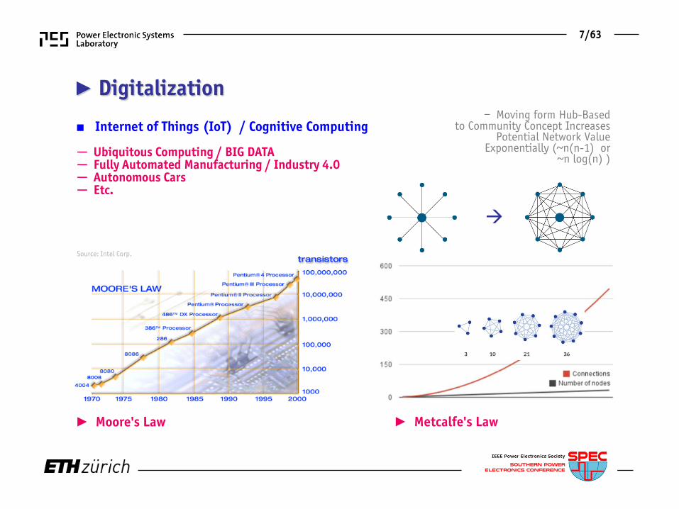
► Digitalization
■ Internet of Things (IoT) / Cognitive Computing
► Moore's Law ► Metcalfe's Law
─ Ubiquitous Computing / BIG DATA─ Fully Automated Manufacturing / Industry 4.0─ Autonomous Cars ─ Etc.
– Moving form Hub-Basedto Community Concept Increases
Potential Network Value Exponentially (~n(n-1) or
~n log(n) )
7/63
Source: Intel Corp.

Server-Farmsup to 450 MW
99.9999%/<30s/a$1.0 Mio./Shutdown
Since 2006 Running Costs >
Initial Costs
─ Ranging from Medium Voltage to Power-Supplies-on-Chip─ Short Power Supply Innovation Cycles─ Modularity / Scalability
─ Higher Power Density (!)─ Higher Efficiency (!)─ Lower Costs
8/63
■ Enabled by Power Electronics
Source: REUTERS/Sigtryggur Ari
Green / Zero Datacenters (1)

► Power Density Increased byFactor 2 over 10 Years
9/63
─ Ranging from Medium Voltage to Power-Supplies-on-Chip─ Short Power Supply Innovation Cycles─ Modularity / Scalability
─ Higher Power Density (!)─ Higher Efficiency (!)─ Lower Costs
■ Enabled by Power Electronics
Green / Zero Datacenters (2)

Fully Automated Manufacturing – Industry 4.0
Source:
─ Lower Costs (!)─ Higher Power Density ─ Self-Sensing etc.
10/63
■ Enabled by Power Electronics

► ABB´s Future Subsea Power Grid “DevelopAll Elements for a Subsea Factory”
11/63
■ Enabled by Power Electronics
Fully Automated Raw Material Extraction
─ High Reliability (!)─ High Power Density (!) Source: matrixengineered.com

GlobalMegatrends
Climate ChangeDigitalization
UrbanizationAlleviate PovertyEtc.
Sustainable Mobility

► Sustainable Mobility
www.theicct.org
■ EU Mandatory 2020 CO2 Emission Targets for New Cars
─ 147g CO2/km for Light-Commercial Vehicles ─ 95g CO2/km for Passenger Cars─ 100% Compliance in 2021
► Hybrid Vehicles► Electric Vehicles
12/63
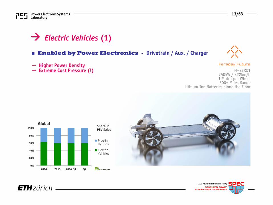
FF-ZERO1750kW / 322km/h1 Motor per Wheel 300+ Miles Range
Lithium-Ion Batteries along the Floor
Electric Vehicles (1)
─ Higher Power Density─ Extreme Cost Pressure (!)
■ Enabled by Power Electronics - Drivetrain / Aux. / Charger
13/63

Electric Vehicles (2)
─ Higher Power Density─ Extreme Cost Pressure (!)
► Typ. 10% / a Cost Reduction► Economy of Scale !
Source: PCIM 2013
14/63
■ Enabled by Power Electronics - Drivetrain / Aux. / Charger

─ Hyperloop ─ San Francisco Los Angeles in 35min
► Low Pressure Tube► Magnetic Levitation► Linear Ind. Motor► Air Compressor in Nose
www.spacex.com/hyperloop
15/63
Futuristic Mobility Concepts (1)
■ Enabled by Power Electronics

► Eff. Optim. Gas Turbine ► 1000Wh/kg Batteries ► Distrib. Fans (E-Thrust)► Supercond. Motors ► Med. Volt. Power Distrib.
Source:
Futuristic Mobility Concepts (2)
16/63
■ Enabled by Power Electronics
─ Cut Emissions Until 2050 * CO2 by 75%, * NOx by 90%, * Noise Level by 65%
Future Hybrid Distributed Propulsion Aircraft

Source:
58/6317/63
► Electric Power Distribution ► High Flex. in Generator/Fan Placement► Generators: 2 x 40.2MW / Fans: 14 x 5.74 MW (1.3m Diameter)
NASA N3-X Vehicle Concept using
Turboel. Distrib. Propulsion
Futuristic Mobility Concepts (3)
■ Enabled by Power Electronics

GlobalMegatrends
Climate ChangeDigitalizationSustainable Mobility
Alleviate PovertyEtc.
Urbanization

► Urbanization■ 60% of World Population Exp. to Live in Urban Cities by 2025■ 30 MEGA Cities Globally by 2023
─ Smart Buildings ─ Smart Mobility─ Smart Energy / Grid ─ Smart ICT, etc.
► Selected Current & Future MEGA Cities 2015 2030
Source: World UrbanizationProspects: The 2014 Revision
58/6318/63

Source:
Smart Cities / Grid (1)
19/63
■ Enabled by Power Electronics
www.masdar.ae
─ Masdar = “Source”─ Fully Sustainable Energy Generation
* Zero CO2* Zero Waste
─ EV Transport / IPT Charging─ to be finished 2025

Source:
20/63
www.masdar.ae
Smart Cities / Grid (2)
■ Enabled by Power Electronics
─ Masdar = “Source”─ Fully Sustainable Energy Generation
* Zero CO2* Zero Waste
─ EV Transport / IPT Charging─ to be finished 2025

GlobalMegatrends
Climate ChangeDigitalizationSustainable MobilityUrbanization
Etc.Alleviate Poverty

► Urgent Need for Village-Scale Solar DC Microgrids etc. ► 2 US$ for 2 LED Lights + Mobile-Phone Charging / Household / Month (!)
21/63
► Alleviate Poverty■ 2 Billion “Bottom-of-the-Pyramid People” are Lacking Access to Clean Energy ■ Rural Electrification in the Developing World

… in SummarySource: whiskeybehavior.info
22/63
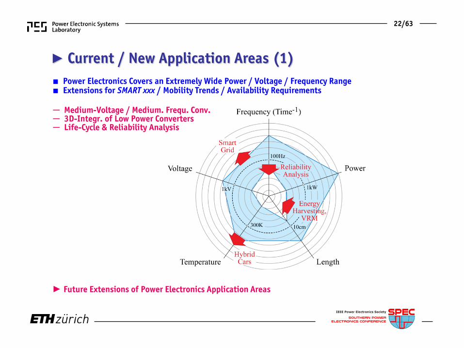
► Future Extensions of Power Electronics Application Areas
■ Power Electronics Covers an Extremely Wide Power / Voltage / Frequency Range■ Extensions for SMART xxx / Mobility Trends / Availability Requirements
─ Medium-Voltage / Medium. Frequ. Conv.─ 3D-Integr. of Low Power Converters─ Life-Cycle & Reliability Analysis
► Current / New Application Areas (1)

23/63
► Cost Pressure as Common Denominator of All Applications (!)► Key Importance of Technology Partnerships of Academia & Industry
■ Commoditization / Standardization for High Volume Applications ■ Extension to Microelectronics-Technology (Power Supply on Chip)■ Extensions to MV/MF
► Current / New Application Areas (2)

24/63
► Future “Big-Bang” Disruptions■ “Catastrophic” Success of Disruptive New (Digital) Technologies■ No Bell-Curve Technology Adoption / Technology S-Curve ■ “Shark Fin“-Model
► Consequence: Market Immediately & Be Ready to Scale Up ─ and Exit ─ Swiftly (!)
Source: www.verschuerent.wordpress.comFebruary 2015
See also: Big Bang Disruption –Strategy in the Age of
Devastating Innovation, L. Downes and P. Nunes

Mutual Coupling of PerformancesNew Integration Technologies
Power Converter Design Challenges

Mutual Coupling of PerformancesNew Integration Technologies
Power Converter Design Challenges

► Required Power Electronics Performance Improvements
─ Power Density [kW/dm3]─ Power per Unit Weight [kW/kg]─ Relative Costs [kW/$]─ Relative Losses [%]─ Failure Rate [h-1]
■ Performance Indices
[kgFe /kW] [kgCu /kW][kgAl /kW][cm2
Si /kW]
►
►
Environmental Impact…
25/63

► Multi-Objective Design Challenge (1)
■ Counteracting Effects of Key Design Parameters■ Mutual Coupling of Performance Indices Trade-Offs
Large Number of Degrees of Freedom / Multi-Dimensional Design Space Full Utilization of Design Space only Guaranteed by Multi-Objective Optimization
26/63

27/63
► Multi-Objective Design Challenge (1)
Large Number of Degrees of Freedom / Multi-Dimensional Design Space Full Utilization of Design Space only Guaranteed by Multi-Objective Optimization
■ Counteracting Effects of Key Design Parameters■ Mutual Coupling of Performance Indices Trade-Offs

■ Specific Performance Profiles / Trade-OffsDependent on Application
28/63
► Multi-Objective Design Challenge (2)

► Remark: Visualization of Multiple Performances ;-)
► H. Chernoff (Stanford): “The Use of Faces to Represent Points in K-Dimensional Space Graphically”
■ Spider Charts, etc.■ Chernoff-Faces
29/63

Mutual Coupling of PerformancesNew Integration Technologies
Power Converter Design Challenges

30/63
► Advanced Technologies / Extreme Integration
■ Industry Is Leading the Field (!)
─ Cutting Edge Converters (up to 1.5kW) 3D-Integrated (!)─ PCB Based Demonstrators Do NOT Provide Much Information (!)
■ Future Role of Universities in Question (!)
─ Not Any More Many “Low Hanging” Fruits─ Solution of Non-Problems vs. Non-Solution of Problems─ Industry Technology Partnership for Technology Access─ “Fab-Less” Research @ Universities?
► Research on Multi-Objective Design / Virtual Prototyping as Natural Consequence (!)
Citation: L.H. Fink

Multi-ObjectiveOptimization
Abstraction of Converter DesignDesign Space / Performance SpacePareto FrontSensitivities / Trade-Offs

Mapping of “Design Space” into System “Performance Space”
Performance Space
Design Space
► Abstraction of Power Converter Design
31/63

► Mathematical Modelingof the Converter Design
Multi-Objective Optimization – Guarantees Best Utilization of All Degrees of Freedom (!)
32/63

► Multi-Objective Optimization (1)
■ Ensures Optimal Mapping of the “Design Space” into the “Performance Space”■ Identifies Absolute Performance Limits Pareto Front / Surface
Clarifies Sensitivity to Improvements of Technologies Trade-off Analysis
/p krr
∆ ∆
33/63

► Determination of the η-ρ-Pareto Front (a)
─ Core Geometry / Material─ Single / Multiple Airgaps─ Solid / Litz Wire, Foils─ Winding Topology─ Natural / Forced Conv. Cooling─ Hard-/Soft-Switching─ Si / SiC─ etc.─ etc.─ etc.
─ Circuit Topology─ Modulation Scheme─ Switching Frequ.─ etc.─ etc.
■ System-Level Degrees of Freedom
■ Comp.-Level Degrees of Freedom of the Design
■ Only η -ρ -Pareto Front Allows ComprehensiveComparison of Converter Concepts (!)
34/63

■ Example: Consider Only fP as Design Parameter
fP =100kHz
“Pareto Front”
► Determination of the η-ρ-Pareto Front (b)
■ Only the Consideration of All Possible Designs / Degreesof Freedom Clarifies the Absolute η-ρ-Performance Limit
35/63

► Multi-Objective Optimization (2)
■ Design Space Diversity■ Equal Performance for Largely Different Sets of Design Parameters
E.g. Mutual Compensation of Volume and Loss Contributions (e.g. Cond. & Sw. Losses) Allows Optimization for Further Performance Index (e.g. Costs)
36/63

► Converter Performance Evaluation Based on η-ρ-σ-Pareto Surface
■ Definition of a Power Electronics “Technology Node” (η*,ρ*,σ*,fP*)■ Maximum σ [kW/$], Related Efficiency & Power Density
►
Specifying Only a Single Performance Index is of No Value (!) Achievable Perform. Depends on Conv. Type / Specs (e.g. Volt. Range) / Side Cond. (e.g. Cooling)
37/63

► Converter Performance Evaluation Based on η-ρ-σ-Pareto Surface
■ Definition of a Power Electronics “Technology Node” (η*,ρ*,σ*,fP*)■ Maximum σ [kW/$], Related Efficiency & Power Density
Specifying Only a Single Performance Index is of No Value (!) Achievable Perform. Depends on Conv. Type / Specs (e.g. Volt. Range) / Side Cond. (e.g. Cooling)
38/63
►

► Remark: Comparison to “Moores Law”
Definition of “η*,ρ*,σ*,fP*–Node” Must Consider Conv. Type / Operating Range etc. (!)
39/63
■ “Moores Law” Defines Consecutive Techn. Nodes Based on Min. Costs per Integr. Circuit (!)■ Complexity for Min. Comp. Costs Increases approx. by Factor of 2 / Year
Gordon Moore: The Future of Integrated Electronics, 1965 (Consideration of Three Consecutive TechnologyNodes)
LowerYield
Economy ofScale
>2015: Smaller Transistors but Not any more Cheaper►

Multi-Objective Optimization
Application ExamplesComparative Converter EvaluationImpact of Technology ProgressDesign Space Diversity
Multi-Objective Optimization
Application ExamplesComparative Converter EvaluationImpact of Technology ProgressDesign Space Diversity

Example #1
Two-Level vs. Three-Level Dual Active Bridge
Source: SMA

► Wide Input Voltage Range Isolated DC/DC Converter
─ Bidirectional Power Flow─ Galvanic Isolation─ Wide Voltage Range─ High Partial Load Efficiency
■ Universal Isolated DC/DC Converter
►Structure of “Smart Home“ DC Microgrid ►Universal DC/DC Converter
─ Reduced System Complexity─ Lower Overall Development Costs─ Economy of Scale
■ Advantages
40/63
!

► Comparative Evaluation of Converter Topologies
■ Conv. 3-Level Dual Active Bridge (3L-DAB)
■ Advanced 5-Level Dual Active Bridge (5L-DAB)
41/63

► Optimization Results - Pareto Surfaces
■ 3-Level Dual Active Bridge■ 5-Level Dual Active Bridge
42/63

Example #2
Performance & Life-Cycle-Costs of Si vs. SiC
Source: L. Lalonde / electronicdesign.com

─ Typical Residential Application─ Single-Input/Single-MPP-Tracker Multi-String PV Inverter─ DC/DC Boost Converter for Wide MPP Voltage Range─ Output EMI Filter
Exploit Excellent Hard- AND Soft-Switching Capabilities of SiC Find Useful Sw. Frequency and Current Ripple Ranges Find Appropriate Core Material
► Multi-Objective η-ρ-σ-Comparison of Si vs. SiC
■ Three-Phase PV Inverter System
43/63

■ Si IGBT 3L-PWM Inverter
► Topologies - Converter Stages
■ SiC MOSFETInterleaved2L-TCM Inverter
■ SiC MOSFET2L-PWM Inverter
44/63

► Optimization Results - Pareto Surfaces
─ No Pareto-Optimal Designsfor fsw,min> 60 kHz
─ No METGLAS Amorphous Iron Designs
─ Pareto-Optimal Designs for Entire Considered fsw Range
─ No METGLAS Amorphous Iron Designs
─ Pareto-Optimal Designs for Entire Considered fsw Range
─ METGLAS Amorphous Iron and Ferrite Designs
45/63
SiC SiC Si

► Optimization Results – Investigations Along Pareto Surfaces
η ρ σ
• 2L-TCM
• 2L-PWM
• 3L-PWM
Semiconductor Losses Clearly Dominating (35…70%)
■ Comparison of theInverter Concepts
46/63
SiC SiC Si
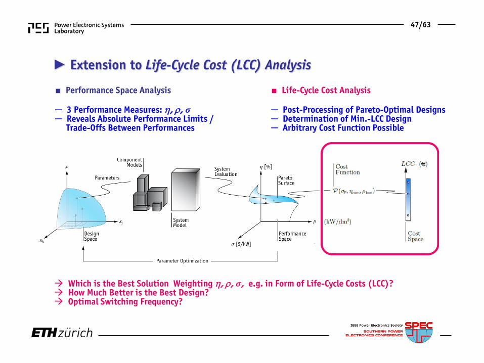
► Extension to Life-Cycle Cost (LCC) Analysis
Which is the Best Solution Weighting η, ρ, σ, e.g. in Form of Life-Cycle Costs (LCC)? How Much Better is the Best Design? Optimal Switching Frequency?
■ Performance Space Analysis
─ 3 Performance Measures: η, ρ, σ─ Reveals Absolute Performance Limits /
Trade-Offs Between Performances
■ Life-Cycle Cost Analysis
─ Post-Processing of Pareto-Optimal Designs─ Determination of Min.-LCC Design─ Arbitrary Cost Function Possible
47/63

► Post-Processing
─ 22% Lower LCC than 3L-PWM─ 5% Lower LCC than 2L-TCM─ Simplest Design─ Probably Highest Reliability─ Lower Vol. (Housing) Not Yet Considered!
■ Best System - 2L-PWM SiC Converter@ 44kHz & 50% Current Ripple
■ Life-Cycle Cost Analysis
Application of SiC Justified on “System Level”
►
48/63
SiC SiC Si

Inductive Power Transfer Example #3
Source: www.qualcomm.com

► Multi-Objective Optimization of 5kW Prototype
■ Design Process Taking All Performance Aspects into Account
■ System Specification- Input Voltage 400V- Battery Voltage 350V- Output Power 5kW- Air Gap 50mm
■ Constraints / Side Conditions- Thermal Limitations [°C]- Stray Field Limits [μT]- Max. Constr. Vol. [m3]- Switching Frequency [kHz]
■ System Performance* Efficiency η = Pout/Pin [%]* Power Density α = Pout/Acoil [kW/dm2] * Stray Field β = Bmax/Bnorm [%]
49/63

► η-α-β-Pareto Coil Optimization■ Encountered Design Trade-Offs
Pareto-Optimization Allows to Study Influence of Key Design Parameters
50/63
* Coil Size vs. Efficiency * Coil Size vs. Stray Field * Frequency vs. Stray Field

Example #4
Electrical System of an Airborne Wind Turbine M. Loyd, 1980

► Airborne Wind Turbine (AWT) -
■ Power Kite On-Board Turbine / Generator / Power Electronics■ Power Transmitted to Ground Electrically■ Minimum of Mechanical Support
51/63

■ Rated Power 100kW■ Operating Height 800…1000m■ Ambient Temp. 40°C ■ Power Flow Motor & Generator
El. System Target Weight 100kg Efficiency (incl. Tether) 90% Turbine /Motor 2000/3000rpm
52/63
► AWT Electrical System Structure

► Overall AWT System Performance
■ Final Step: System Control Consideration
►
53/63

Multi-Objective Optimization
Application ExamplesComparative Converter EvaluationImpact of Technology Progress &Design Space Diversity

■ Design / Build the 2kW 1-Φ Solar Inverter with the Highest Power Density in the World■ Power Density > 3kW/dm3 (50W/in3)■ Efficiency > 95%■ Case Temp. < 60°C■ EMI FCC Part 15 B
Push the Forefront of New Technologies in R&D of High Power Density Inverters
!
!
!
!
54/63

Selected Converter Topology
ZVS of All Bridge Legs @ Turn-On/Turn-Off in Whole Operating Range (4D-TCM-Interleaving) Heatsinks Connected to DC Bus / Shield to Prevent Cap. Coupling to Grounded Enclosure
■ Interleaving of 2 Bridge Legs per Phase ■ Active DC-Side Buck-Type Power Pulsation Buffer■ 2-Stage EMI AC Output Filter
55/63

Little-Box 1.0 Prototype
– 8.2 kW/dm3
– 96,3% Efficiency @ 2kW– Tc=58°C @ 2kW
■ Performance
Analysis of Potential Performance Improvement for “Ideal Switches”
– 600V IFX Normally-Off GaN GIT – Antiparallel SiC Schottky Diodes – Multi-Airgap Ind. w. Multi-Layer Foil Wdg– Triangular Curr. Mode ZVS Operation– CeraLink Power Pulsation Buffer
■ Design Details
56/63

Analysis of Improvement of Efficiency @ Given Power Density & Maximum Power Density The Ideal Switch is NOT Enough (!)
Little Box 1.0 @ Ideal Switches (TCM)
■ Multi-Objective Optimization of Little-Box 1.0 (X6S Power Pulsation Buffer)■ Step-by-Step Idealization of the Power Transistors■ Ideal Switches: kC= 0 (Zero Cond. Losses); kS= 0 (Zero Sw. Losses)
Zero Output Cap. and Zero Gate Drive Losses
57/63

■ L & fS are Independent Degrees of Freedom■ Large Design Space Diversity (Mutual Compensation of HF and LF Loss Contributions)
ρ = 6kW/dm3
η ≈ 99.35%
L = 50uH fS = 500kHz or 900kHz
58/63
Little Box 1.0 @ Ideal Switches (PWM)

ConclusionsFuture Power Electronics Development Future Virtual Prototyping
“Stairway to Heaven”

► Future Development
More Application Specific Solutions Mature Technology – Cost Optimization @ Given Performance Level Design / Optimize / Verify (All in Simulation) - Faster / Cheaper / Better
■ Megatrends – Renewable Energy / Energy Saving / E-Mobility / “SMART XXX”■ Power Electronics will Massively Spread in Applications
59/63

Multi-Domain Modeling /
Simulation/Optimization
HardwarePrototyping
20%
80%
2015
2025
80%
20%
► Future “Virtual Prototyping”
Main Research Challenges in Modeling (EMI, Reliability, Reduced Order Models etc.) Main Practical Challenge is the Implementation in Industry & Academia ;-)
■ Offers Incredible Design Insight – Quantifies Trade-Offs / Technology Sensitivities (!)■ Extends Theory of Components – “Theory of Systems”■ Reduces Time-to-Market – Cuts Design Time from Weeks to Hours
60/63
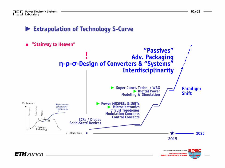
Power MOSFETs & IGBTsMicroelectronics
Circuit TopologiesModulation Concepts
Control Concepts
Super-Junct. Techn. / WBGDigital Power
Modeling & Simulation
20252015
►►
►►
SCRs / Diodes Solid-State Devices
► Extrapolation of Technology S-Curve
“Passives”Adv. Packaging
η-ρ-σ-Design of Converters & “Systems”Interdisciplinarity
ParadigmShift
■
61/63
■ “Stairway to Heaven”
!

Future Paradigm
Shift

■ Design Considering Converters as “Integrated Circuits” (PEBBs)■ Extend Analysis to Converter Clusters / Power Supply Chains / etc.
─ “Converter” “Systems” (Microgrid) or “Hybrid Systems” (Automation / Aircraft)─ “Time” “Integral over Time”─ “Power” “Energy”
( )p t0
( )dtp t t∫
─ Power Conversion Energy Management / Distribution ─ Converter Analysis System Analysis (incl. Interactions Conv. / Conv. or Load or Mains) ─ Converter Stability System Stability (Autonom. Cntrl of Distributed Converters)─ Cap. Filtering Energy Storage & Demand Side Management─ Costs / Efficiency Life Cycle Costs / Mission Efficiency / Supply Chain Efficiency─ etc.
► Power Electronics 2.0
62/63

► New Power Electronics SystemsPerformance Figures/Trends
─ Power Density [kW/m2]─ Environm. Impact [kWs/kW]─ TCO [$/kW]─ Mission Efficiency [%]─ Failure Rate [h-1]
■ Complete Set of New Performance Indices
►►
Supply Chain &
►
63/63

■ End

Thank You !