Embed Size (px)
Citation preview
Multi-mode quantum noisemodel for advanced
gravitational wave detectors
Project Report
McKenna DavisJune 3, 2016 - July 29, 2016University of Birmingham
School of Physics and Astronomy
Contents
1 Abstract 2
2 Introduction to FINESSE and the Use of Squeezed Light inGravitational Wave Detectors 2
3 Single Mode Coherent Light and Squeezed Light 4
3.1 Calculating Power . . . . . . . . . . . . . . . . . . . . . . . . . . 4
3.2 Calculating Power Spectral Density . . . . . . . . . . . . . . . . . 6
4 Multi-Mode Coherent Light and Squeezed Light 7
4.1 Calculating Power . . . . . . . . . . . . . . . . . . . . . . . . . . 7
4.2 Calculating Power Spectral Density . . . . . . . . . . . . . . . . . 9
4.3 Comparing Analytical Results to FINESSE Simulation . . . . . . 10
5 Single Mode Coherent Light and Squeezed Light with a FilterCavity 14
5.1 Calculating Power . . . . . . . . . . . . . . . . . . . . . . . . . . 14
5.2 Calculating Power Spectral Density . . . . . . . . . . . . . . . . . 18
6 Multi-Mode Coherent Light and Squeezed Light with a FilterCavity 20
6.1 Calculating Power . . . . . . . . . . . . . . . . . . . . . . . . . . 20
6.2 Calculating Power Spectral Density . . . . . . . . . . . . . . . . . 22
6.3 Comparing Analytical Results to FINESSE Simulation . . . . . . 23
7 Conclusion 26
8 Acknowledgements and References 26
1
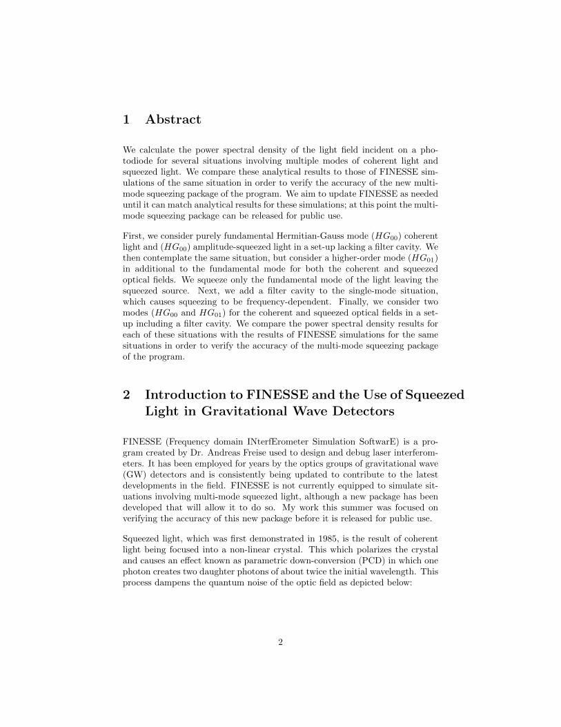
1 Abstract
We calculate the power spectral density of the light field incident on a pho-todiode for several situations involving multiple modes of coherent light andsqueezed light. We compare these analytical results to those of FINESSE sim-ulations of the same situation in order to verify the accuracy of the new multi-mode squeezing package of the program. We aim to update FINESSE as neededuntil it can match analytical results for these simulations; at this point the multi-mode squeezing package can be released for public use.
First, we consider purely fundamental Hermitian-Gauss mode (HG00) coherentlight and (HG00) amplitude-squeezed light in a set-up lacking a filter cavity. Wethen contemplate the same situation, but consider a higher-order mode (HG01)in additional to the fundamental mode for both the coherent and squeezedoptical fields. We squeeze only the fundamental mode of the light leaving thesqueezed source. Next, we add a filter cavity to the single-mode situation,which causes squeezing to be frequency-dependent. Finally, we consider twomodes (HG00 and HG01) for the coherent and squeezed optical fields in a set-up including a filter cavity. We compare the power spectral density results foreach of these situations with the results of FINESSE simulations for the samesituations in order to verify the accuracy of the multi-mode squeezing packageof the program.
2 Introduction to FINESSE and the Use of SqueezedLight in Gravitational Wave Detectors
FINESSE (Frequency domain INterfErometer Simulation SoftwarE) is a pro-gram created by Dr. Andreas Freise used to design and debug laser interferom-eters. It has been employed for years by the optics groups of gravitational wave(GW) detectors and is consistently being updated to contribute to the latestdevelopments in the field. FINESSE is not currently equipped to simulate sit-uations involving multi-mode squeezed light, although a new package has beendeveloped that will allow it to do so. My work this summer was focused onverifying the accuracy of this new package before it is released for public use.
Squeezed light, which was first demonstrated in 1985, is the result of coherentlight being focused into a non-linear crystal. This which polarizes the crystaland causes an effect known as parametric down-conversion (PCD) in which onephoton creates two daughter photons of about twice the initial wavelength. Thisprocess dampens the quantum noise of the optic field as depicted below:
2
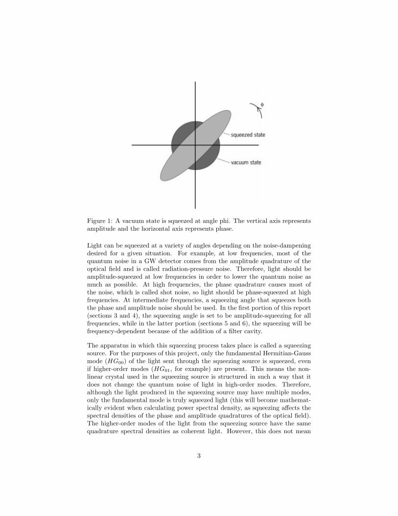
Figure 1: A vacuum state is squeezed at angle phi. The vertical axis representsamplitude and the horizontal axis represents phase.
Light can be squeezed at a variety of angles depending on the noise-dampeningdesired for a given situation. For example, at low frequencies, most of thequantum noise in a GW detector comes from the amplitude quadrature of theoptical field and is called radiation-pressure noise. Therefore, light should beamplitude-squeezed at low frequencies in order to lower the quantum noise asmuch as possible. At high frequencies, the phase quadrature causes most ofthe noise, which is called shot noise, so light should be phase-squeezed at highfrequencies. At intermediate frequencies, a squeezing angle that squeezes boththe phase and amplitude noise should be used. In the first portion of this report(sections 3 and 4), the squeezing angle is set to be amplitude-squeezing for allfrequencies, while in the latter portion (sections 5 and 6), the squeezing will befrequency-dependent because of the addition of a filter cavity.
The apparatus in which this squeezing process takes place is called a squeezingsource. For the purposes of this project, only the fundamental Hermitian-Gaussmode (HG00) of the light sent through the squeezing source is squeezed, evenif higher-order modes (HG01, for example) are present. This means the non-linear crystal used in the squeezing source is structured in such a way that itdoes not change the quantum noise of light in high-order modes. Therefore,although the light produced in the squeezing source may have multiple modes,only the fundamental mode is truly squeezed light (this will become mathemat-ically evident when calculating power spectral density, as squeezing affects thespectral densities of the phase and amplitude quadratures of the optical field).The higher-order modes of the light from the squeezing source have the samequadrature spectral densities as coherent light. However, this does not mean
3
that the higher-order modes of the squeezed light are equivalent to those of anyother coherent light, as they may not be from the same source and thus may nothave the same amplitude. In fact, squeezed light contains so few photons thatwe consider its amplitude to be negligible in comparison to that of the coherentlight. In this project, the squeezed source and laser source are separate, so thesqueezed light higher-order modes are different from those of the coherent light.
In the most recent update to LIGO, the advanced GW detector was equippedto use squeezed light to reduce quantum noise. Therefore, software that canaccurately model squeezed light in multi-mode scenarios is necessary to allowfor further advancements to be made in its use of squeezed light. FINESSE hasbeen instrumental in many past improvements to LIGO and this new packagewill allow it to continue to be so in the study of the benefits of squeezed light.
3 Single Mode Coherent Light and Squeezed Light
3.1 Calculating Power
Mirror
Mirror
Squeezing Source
LaserPhoto Detector
L
L
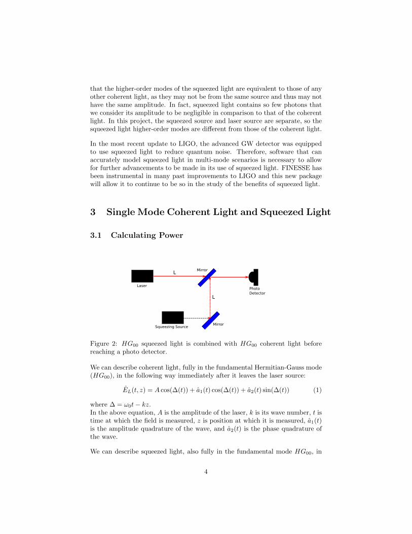
Figure 2: HG00 squeezed light is combined with HG00 coherent light beforereaching a photo detector.
We can describe coherent light, fully in the fundamental Hermitian-Gauss mode(HG00), in the following way immediately after it leaves the laser source:
EL(t, z) = A cos(∆(t)) + a1(t) cos(∆(t)) + a2(t) sin(∆(t)) (1)
where ∆ = ω0t− kz.In the above equation, A is the amplitude of the laser, k is its wave number, t istime at which the field is measured, z is position at which it is measured, a1(t)is the amplitude quadrature of the wave, and a2(t) is the phase quadrature ofthe wave.
We can describe squeezed light, also fully in the fundamental mode HG00, in
4
the following way immediately after it leaves the squeezing source:
ESL = a1S(t) cos(∆(t)− θ) + a2S(t) sin(∆(t)− θ) (2)
where a1S(t) is the amplitude quadrature of the squeezed light, a2S(t) is itsphase quadrature, and θ is an arbitrary phase difference between the squeezedlight and the coherent light that can be set to any desired value. The squeezedlight has no amplitude term A because it is comprised of so few photons thatits amplitude is negligible in comparison to that of the coherent laser light.
We assume that the first mirror is a negligible distance away from the squeezingsource so there is no phase change as the field propagates from the source to themirror. We also assume the bottom mirror has a reflectivity of 1 so all of thesqueezed light is reflected upon reaching it. Thus the squeezed light equationESL is not affected by that mirror.
The squeezed light then travels a distance L to the top mirror. The field ESLundergoes a phase change as it propagates that distance. Time has passed asit propagated so the optical field is now a function of t′. Therefore, just beforereaching the top mirror:
ESL = a1S(t′) cos(∆(t′)− θ) + a2S(t′) sin(∆(t′)− θ)
= a1S(t′) cos(∆(t′)) cos(θ) + a1S(t′) sin(∆(t′)) sin(θ) + a2S(t′) sin(∆(t′)) cos(θ)− a2S(t′) cos(∆(t′)) sin(θ)
= [a1S(t′) cos(θ)− a2S(t′) sin(θ)] cos(∆(t′)) + [a1S(t′) sin(θ) + a2S(t′) cos(θ)] sin(∆(t′))
(3)
The coefficients of this equation can be written in matrix form.(b1S(t′)
b2S(t′)
)=
(cos(θ) − sin(θ)sin(θ) cos(θ)
)(a1S(t′)a2S(t′)
)(4)
where b1S(t′) is the coefficient of the cos(∆(t′)) term and b2S(t′) is the coefficientof the sin(∆(t′)) term.
We assume the coherent laser light also travels a distance L before reaching thetop mirror so the only phase difference it has from the squeezed light is θ. Wealso assume the top mirror has a very high reflectivity and a very low transmis-sivity so very little coherent light (which has a high amplitude) is transmittedwhile almost all of the squeezed light is reflected. This allows the noise-reducingeffects of the squeezed light to be maximized while also providing enough ampli-tude from the coherent light for the field to be recognized by the photo detector.The squeezed light (reflected by the mirror) and the coherent light (transmittedthrough the mirror) combine to make ESLS , which has the following coefficients
5
for its cos(∆(t′)) and sin(∆(t′)) terms:(b1(t′)
b2(t′)
)= r2
(cos(θ) − sin(θ)sin(θ) cos(θ)
)(a1S(t′)a2S(t′)
)+ t2
(a1(t′)a2(t′)
)+ t2
(A0
)(5)
The reflection coefficient of the mirror is r2 and the transmission coefficient ist2. We assume the distance between the mirror and the photo diode is negligibleso ELSL does not undergo a phase change while propagating towards the photodiode.
The power observed by the photo diode is P = hω0E2LSL. Ignoring higher order
terms that occur when quadratures are multiplied by one another leaves termsfrom the quadratures multiplied by the amplitude and the constant term fromthe amplitude squared.
P (t, z) = hω02r2t2A[cos(θ)a1S(t′)−sin(θ)a2S(t′)] cos2(∆(t′))+2t22Aa1(t′) cos2(∆(t′))+t22A2 cos2(∆(t′))
(6)Next we apply double angle formulas to the trigonometric squared terms andremove the resulting fast-oscillating terms of the form cos(2ω0t) or sin(2ω0t).These pieces can be removed because the photo diode can only resolve frequen-cies up to around 10 MHz and ω0 is in the THz order of magnitude. In addition,power is defined as the average energy per period of the oscillating electromag-netic field, so the oscillating terms can be ignored as their time-averages arezero. This yields the power:
P (t, z) = hω0t2Ar2[cos(θ)a1S(t′)− sin(θ)a2S(t′)] + t2a1(t′) +t2A
2 (7)
Removing the constant amplitude term yields the power contributed by thequadratures (the fluctuating power):
P (t, z) = hω0t2Ar2[cos(θ)a1S(t′)− sin(θ)a2S(t′)] + t2a1(t′) (8)
3.2 Calculating Power Spectral Density
Power spectral density is defined as
1
2S(Ω)PP δ(Ω− Ω′) ≡ 1
2π〈0|P (Ω)P (Ω′)† + P (Ω′)P (Ω)†|0〉 (9)
Fourier transforming P (t, z) yields P (Ω, z):
P (Ω, z) = hω0t2Ar2[cos(θ)a1S(Ω)− sin(θ)a2S(Ω)] + t2a1(Ω) (10)
6
Substituting this power into the power spectral density equation:
1
2S(Ω)PP δ(Ω− Ω′)
= (hω0t2A)2 1
2π〈0|r2[cos(θ)a1S(Ω)− sin(θ)a2S(Ω)] + t2a1(Ω)r2[cos(θ)a†1S(Ω′)− sin(θ)a†2S(Ω′)] + t2a
†1(Ω′)
+ r2[cos(θ)a1S(Ω′)− sin(θ)a2S(Ω′)] + t2a1(Ω′)r2[cos(θ)a†1S(Ω)− sin(θ)a†2S(Ω)] + t2a†1(Ω)|0〉
(11)
We assume all phase and amplitude quadratures are uncorrelated, that is, allcross-quadrature terms will go to zero. This is not the case in all GW-detectorsituations, but it is an assumption we can make for the purposes of verifyingthe new FINESSE package:
1
2S(Ω)PP δ(Ω− Ω′) = (hω0t2A)2 1
2π〈0|[(r2 cos(θ))2[a1S(Ω)a†1S(Ω′) + a1S(Ω′)a†1S(Ω)]
+ (r2 sin(θ))2[a2S(Ω)a†2S(Ω′) + a2S(Ω′)a†2S(Ω)] + t22[a1(Ω)a†1(Ω′) + a1(Ω′)a†1(Ω)]|0〉(12)
Next we substitute in known quadrature spectral densities S1S1S = e−2r, S2S2S =e2r, and S11 = 1. Here r is the squeezing factor, which is dependent on the powerof the light pumped into the squeezing source.
1
2S(Ω)PP δ(Ω−Ω′) = (hω0t2A)2 1
2δ(Ω−Ω′)[(r2 cos(θ))2e−2r+(r2 sin(θ))2e2r+t22]
(13)
Dividing both sides of the equation by 12δ(Ω − Ω′) yields the power spectral
density.
S(Ω)PP = (hω0t2A)2[(r2 cos(θ)e−r)2 + (r2 sin(θ)er)2 + t22] (14)
4 Multi-Mode Coherent Light and Squeezed Light
4.1 Calculating Power
Coherent light in the fundamental Hermitian-Gauss mode (HG00) and onehigher order mode (HG01) can be described in the following way immediatelyafter leaving the laser source:
E00/01L (t, z) = [A00 + a00
1 (t) +A01 + a011 (t)] cos(∆(t)) + [a00
2 (t) + a012 (t)] sin(∆(t))
(15)where ∆(t) = ω0t− kz.
7
This coherent light travels a distance L to the mirror, undergoing a phasechange. When it reaches the mirror it is described by:
E00/01L (t′, z) = [A00+a00
1 (t′)+A01+a011 (t′)] cos(∆(t′))+[a00
2 (t′)+a012 (t′)] sin(∆(t′))
(16)
Squeezed light in the same two modes, immediately after leaving the squeezingsource, can be described similarly as shown below. For the purpose of com-parisons with FINESSE, only the fundamental mode of the light is squeezed inthe squeezing source. This will become mathematically significant later whencalculating power spectral density.
E00/01SL (t, z) = [a00
1S(t) + a011S(t)] cos(∆(t)− θ) + [a00
2S(t) + a012S(t)] sin(∆(t)− θ)
= [a001S(t) + a01
1S(t)][cos(∆(t)) cos(θ) + sin(∆(t)) sin(θ)]
+ [a002S(t) + a01
2S(t)][sin(∆(t)) cos(θ)− cos(∆(t)) sin(θ)]
= [a001S(t) cos(θ) + a01
1S(t) cos(θ)− a002S(t) sin(θ)− a01
2S(t) sin(θ)] cos(∆(t))
+ [a002S(t) cos(θ) + a01
2S(t) cos(θ) + a001S(t) sin(θ) + a01
1S(t) sin(θ)] sin(∆(t))
(17)
where θ is the phase difference between the squeezed light and coherent light ofour choosing.
We again assumed that the distance between the squeezing source and thefirst/bottom mirror is negligible and the mirror has a reflectivity of one. Thesqueezed light then travels a distance L to the second/top mirror, undergoingthe same phase change as the coherent light:
E00SL(t′, z) = [a00
1S(t′) cos(θ) + a011S(t′) cos(θ)− a00
2S(t′) sin(θ)− a012S(t′) sin(θ)] cos(∆(t′))
+ [a002S(t′) cos(θ) + a01
2S(t′) cos(θ) + a001S(t′) sin(θ) + a01
1S(t′) sin(θ)] sin(∆(t′))
(18)
Adding the coherent light transmitted through the top/second mirror (withtransmissivity t2 and reflectivity r2) to the squeezed light reflected off of ityields the field approaching the photo detector. We assuming again that thedistance between the mirror and the photo diode is negligible.
E00/01LSL (t′, z) =t2[A00 + a00
1 (t′) +A01 + a011 (t′)]
+ r2[a001S(t′) cos(θ) + a01
1S(t′) cos(θ)− a002S(t′) sin(θ)− a01
2S(t′) sin(θ)] cos(∆(t′))
+ t2[a002 (t′) + a01
2 (t′)] + r2[a002S(t′) cos(θ)
+ a012S(t′) cos(θ) + a00
1S(t′) sin(θ) + a011S(t′) sin(θ)] sin(∆(t′))
(19)
8
In matrix form, the coefficients for the cos(∆(t′)) (b001 (t′)+ b
01(t′)1 ) and sin(∆(t′))
(b002 (t′) + b01
2 (t′)) terms of the ELSL(t′) are:b001 (t′)
b002 (t′)
b011 (t′)
b012 (t′)
= r2
cos(θ) − sin(θ) 0 0sin(θ) cos(θ) 0 0
0 0 cos(θ) − sin(θ)0 0 sin(θ) cos(θ)
a001S(t′)a00
2S(t′)a01
1S(t′)a01
2S(t′)
+ t2
a00
1 (t′)a00
2 (t′)a01
1 (t′)a01
2 (t′)
+ t2
A00
0A01
0
(20)
Now calculating power (P = hω0E2LSL), ignoring higher-order terms from quadra-
tures multiplied by one another, and using double-angle formulas to removefast-oscillating trigonometric terms:
P (t′, z)00/01 =hω0t2t2(A002
+A012)
2+ t2[A00a00
1 (t′) +A01a011 (t′)]
+ r2[A00(a001S(t′) cos(θ)− a00
2S(t′) sin(θ)) +A01(a011S(t′) cos(θ)− a01
2S(t′) sin(θ))](21)
Removing the constant term to focus on fluctuating power:
P (t′, z)00/01 =hω0t2t2[A00a001 (t′) +A01a01
1 (t′)]
+ r2[A00(a001S(t′) cos(θ)− a00
2S(t′) sin(θ)) +A01(a011S(t′) cos(θ)− a01
2S(t′) sin(θ))](22)
4.2 Calculating Power Spectral Density
First P (t′, z) must Fourier transformed from the time-domain into the frequency-domain.
P (Ω, z)00/01 =hω0t2t2[A00a001 (Ω) +A01a01
1 (Ω)]
+ r2[A00(a001S(Ω) cos(θ)− a00
2S(Ω) sin(θ)) +A01(a011S(Ω) cos(θ)− a01
2S(Ω) sin(θ))](23)
We substitute this equation for power into the power spectral density (PSD)equation (see Eq. 9). Again, the cross-quadrature terms are zero and severalknown quadrature-PSDs can be substituted into the equation. However, sinceonly the fundamental mode of the light from the squeezing source is squeezed,higher-order squeezed light quadratures will have PSDs of one, like those of the
9
coherent light.
1
2S(Ω)PP 00/01δ(Ω− Ω′) =
(hω0t)2
2δ(Ω− Ω′)t22[A002
+A012] + r2
2[A002(cos2(θ)e−2r + sin2(θ)e2r) +A012
(sin2(θ) + cos2(θ))]
=(hω0t)
2
2δ(Ω− Ω′)t22(A002
+A012) + r2
2[A002(cos2(θ)e−2r + sin2(θ)e2r) +A012
]
=(hω0t)
2
2δ(Ω− Ω′)[A002
(t22 + r22 cos2(θ)e−2r + r2
2 sin2(θ)e2r) +A012(t2 + r2)]
=(hω0t)
2
2δ(Ω− Ω′)[A002
(t22 + r22 cos2(θ)e−2r + r2
2 sin2(θ)e2r) +A012]
(24)
Dividing both sides by 12δ(Ω−Ω′) yields the spectral density for the two-mode
situation:
S(Ω)PP 00/01 = (hω0t)2[A002
(t22 + r22 cos2(θ)e−2r + r2
2 sin2(θ)e2r) +A012] (25)
For an arbitrary number of modes, not all of which need be matched betweenthe coherent and squeezed light, the spectral density equation is:
S(Ω)PP 00/.../nm = (hω0t)2[∑
matched
Amn2(t22+r22 cos2(θ)e−2r+r2
2 sin2(θ)e2r)+∑
mismatched
Amn2]
(26)
4.3 Comparing Analytical Results to FINESSE Simula-tion
To verify the multi-mode squeezing package of FINESSE, we compare the square-root of the power spectral density (known as the shot noise) from our analyticalresults to the same value produced by the simulation for varying phase differ-ences (θ) between the coherent and squeezed light. The results are depictedbelow.
Considering the fundamental mode (HG00) case:
It appears that the FINESSE simulation is well-matched with the analyticalsolution for all frequencies. This conclusion is further supported by the low rel-ative error (around order 10−5) between the simulated and analytical solutions:
10
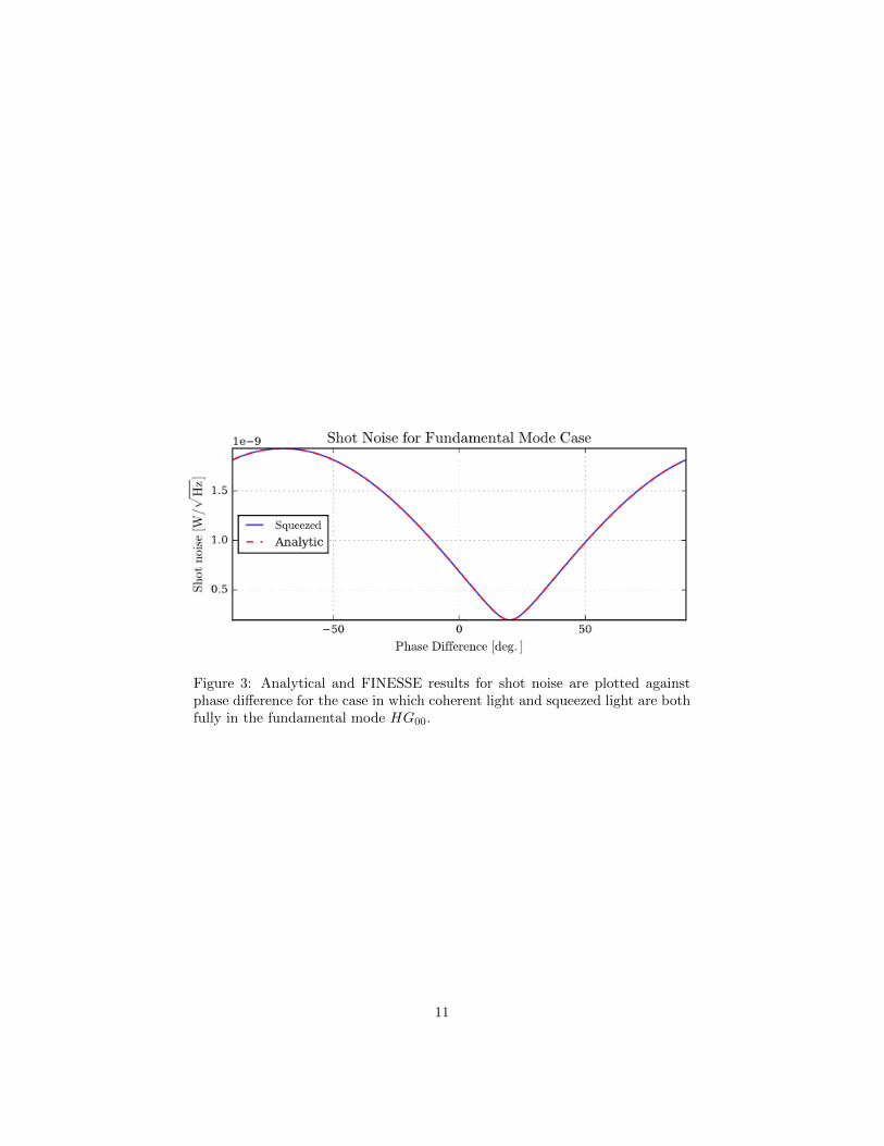
Figure 3: Analytical and FINESSE results for shot noise are plotted againstphase difference for the case in which coherent light and squeezed light are bothfully in the fundamental mode HG00.
11
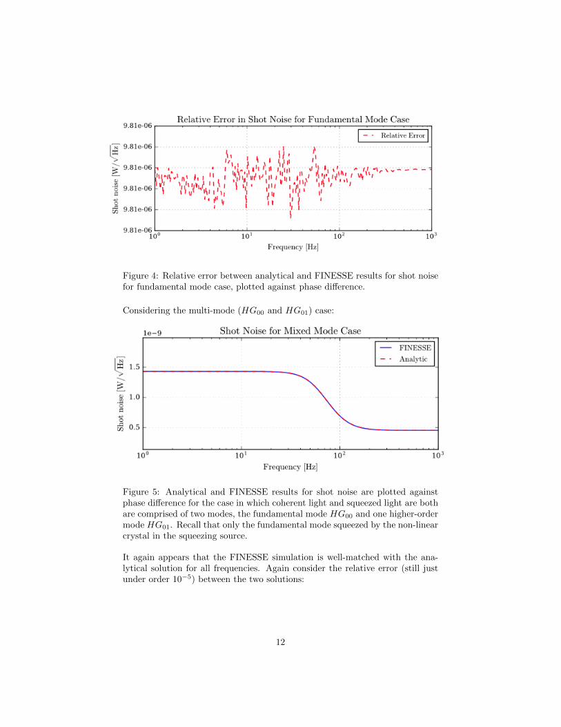
Figure 4: Relative error between analytical and FINESSE results for shot noisefor fundamental mode case, plotted against phase difference.
Considering the multi-mode (HG00 and HG01) case:
Figure 5: Analytical and FINESSE results for shot noise are plotted againstphase difference for the case in which coherent light and squeezed light are bothare comprised of two modes, the fundamental mode HG00 and one higher-ordermode HG01. Recall that only the fundamental mode squeezed by the non-linearcrystal in the squeezing source.
It again appears that the FINESSE simulation is well-matched with the ana-lytical solution for all frequencies. Again consider the relative error (still justunder order 10−5) between the two solutions:
12
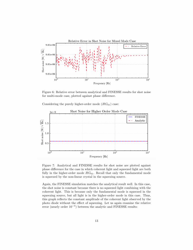
Figure 6: Relative error between analytical and FINESSE results for shot noisefor multi-mode case, plotted against phase difference.
Considering the purely higher-order mode (HG01) case:
Figure 7: Analytical and FINESSE results for shot noise are plotted againstphase difference for the case in which coherent light and squeezed light are bothfully in the higher-order mode HG01. Recall that only the fundamental modeis squeezed by the non-linear crystal in the squeezing source.
Again, the FINESSE simulation matches the analytical result well. In this case,the shot noise is constant because there is no squeezed light combining with thecoherent light. This is because only the fundamental mode is squeezed in thesqueezing source, but all light is in the higher-order mode in this case. Thus,this graph reflects the constant amplitude of the coherent light observed by thephoto diode without the effect of squeezing. Let us again examine the relativeerror (nearly order 10−5) between the analytic and FINESSE results:
13
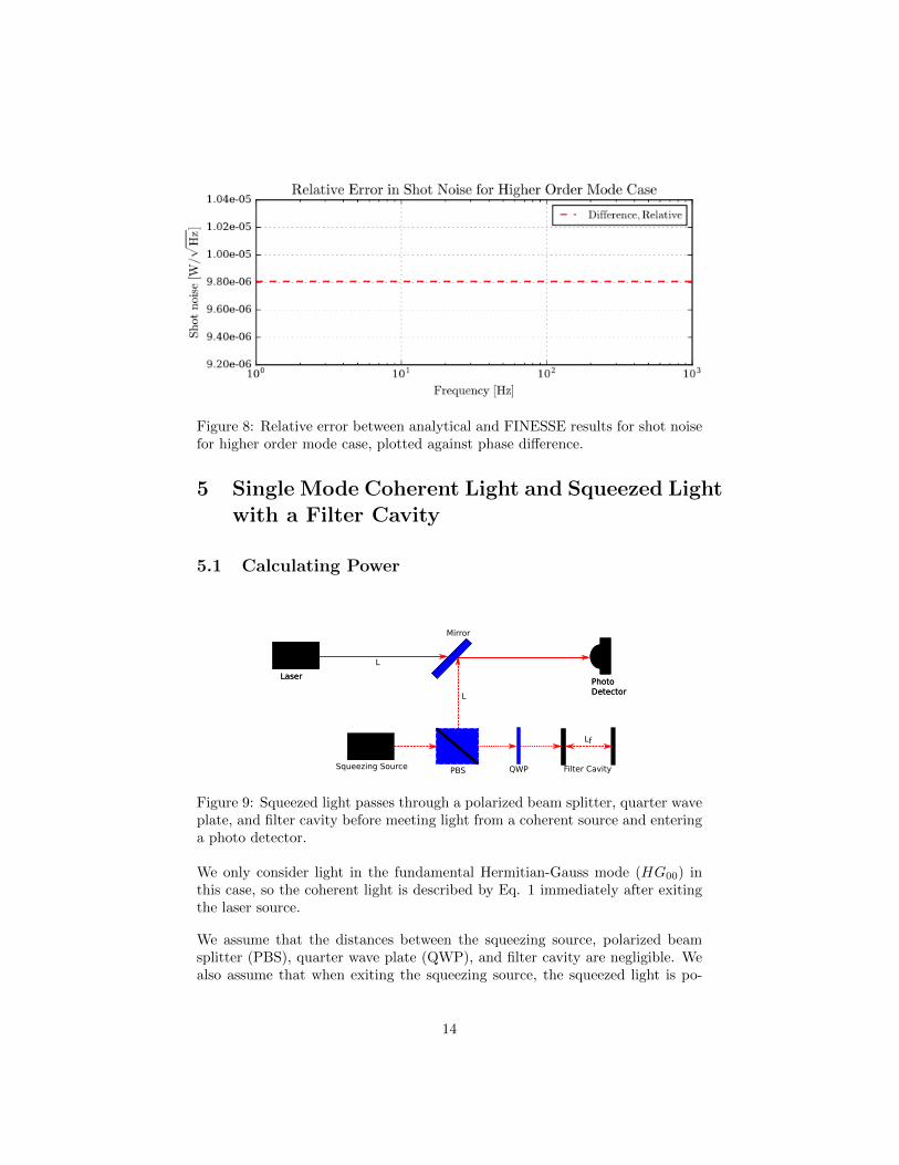
Figure 8: Relative error between analytical and FINESSE results for shot noisefor higher order mode case, plotted against phase difference.
5 Single Mode Coherent Light and Squeezed Lightwith a Filter Cavity
5.1 Calculating Power
PBS
Laser
Mirror
Photo Detector
Squeezing Source
LaserPhoto Detector
QWP Filter Cavity
Lf
L
L
Figure 9: Squeezed light passes through a polarized beam splitter, quarter waveplate, and filter cavity before meeting light from a coherent source and enteringa photo detector.
We only consider light in the fundamental Hermitian-Gauss mode (HG00) inthis case, so the coherent light is described by Eq. 1 immediately after exitingthe laser source.
We assume that the distances between the squeezing source, polarized beamsplitter (PBS), quarter wave plate (QWP), and filter cavity are negligible. Wealso assume that when exiting the squeezing source, the squeezed light is po-
14
larized in such a way that it is fully transmitted through the polarized beamsplitter. When it goes through the QWP it experiences a π
2 change in eitherits x or y-component (perpendicular to its direction of propagation), but itsz-component remains unchanged. Thus, prior to entering the filter cavity, thefundamental-mode squeezed light field is described by Eq. 2.
After exiting the filter cavity, the light passes through the QWP again, causingthe same π
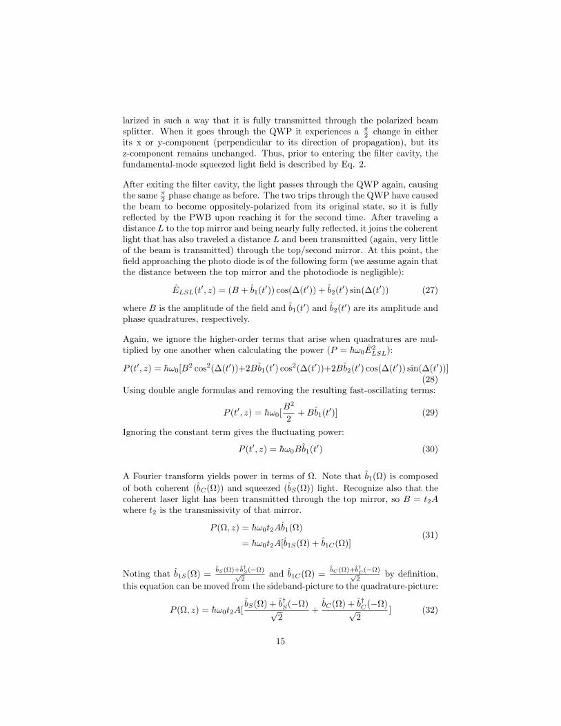
2 phase change as before. The two trips through the QWP have causedthe beam to become oppositely-polarized from its original state, so it is fullyreflected by the PWB upon reaching it for the second time. After traveling adistance L to the top mirror and being nearly fully reflected, it joins the coherentlight that has also traveled a distance L and been transmitted (again, very littleof the beam is transmitted) through the top/second mirror. At this point, thefield approaching the photo diode is of the following form (we assume again thatthe distance between the top mirror and the photodiode is negligible):
ELSL(t′, z) = (B + b1(t′)) cos(∆(t′)) + b2(t′) sin(∆(t′)) (27)
where B is the amplitude of the field and b1(t′) and b2(t′) are its amplitude andphase quadratures, respectively.
Again, we ignore the higher-order terms that arise when quadratures are mul-tiplied by one another when calculating the power (P = hω0E
2LSL):
P (t′, z) = hω0[B2 cos2(∆(t′))+2Bb1(t′) cos2(∆(t′))+2Bb2(t′) cos(∆(t′)) sin(∆(t′))](28)
Using double angle formulas and removing the resulting fast-oscillating terms:
P (t′, z) = hω0[B2
2+Bb1(t′)] (29)
Ignoring the constant term gives the fluctuating power:
P (t′, z) = hω0Bb1(t′) (30)
A Fourier transform yields power in terms of Ω. Note that b1(Ω) is composed
of both coherent (bC(Ω)) and squeezed (bS(Ω)) light. Recognize also that thecoherent laser light has been transmitted through the top mirror, so B = t2Awhere t2 is the transmissivity of that mirror.
P (Ω, z) = hω0t2Ab1(Ω)
= hω0t2A[b1S(Ω) + b1C(Ω)](31)
Noting that b1S(Ω) =bS(Ω)+b†S(−Ω)√
2and b1C(Ω) =
bC(Ω)+b†C(−Ω)√2
by definition,
this equation can be moved from the sideband-picture to the quadrature-picture:
P (Ω, z) = hω0t2A[bS(Ω) + b†S(−Ω)√
2+bC(Ω) + b†C(−Ω)√
2] (32)
15
Here bS(Ω, z) is the annihilation operator of the squeezed light that has passedthrough the filter cavity and the QWP, been reflected fully by the PBS, traveleda distance L to the top mirror (with reflectivity r2), and been reflected. Thusit can be defined as
bS(Ω) = r2e−iθρ(Ω)aS(Ω) (33)
and the creation operator of the squeezed light is
b†S(−Ω) = r2eiθρ∗(−Ω)a†S(−Ω) (34)
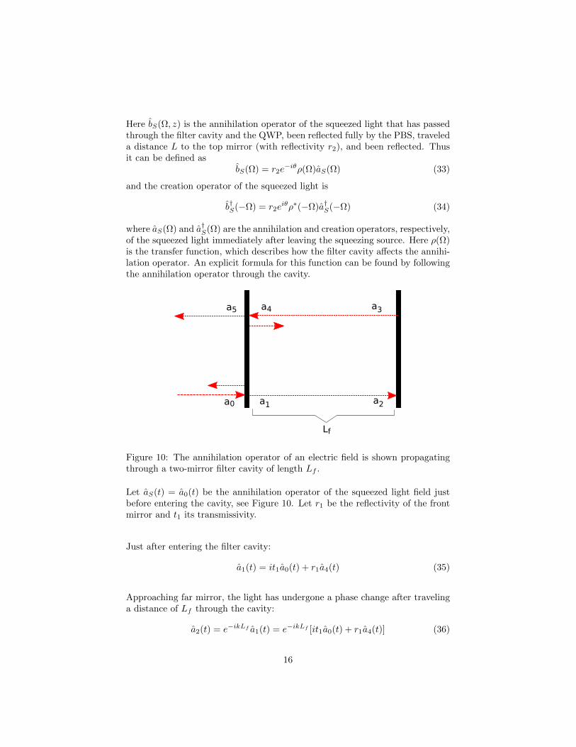
where aS(Ω) and a†S(Ω) are the annihilation and creation operators, respectively,of the squeezed light immediately after leaving the squeezing source. Here ρ(Ω)is the transfer function, which describes how the filter cavity affects the annihi-lation operator. An explicit formula for this function can be found by followingthe annihilation operator through the cavity.
a0 a2a1
a3a4a5
Lf
Figure 10: The annihilation operator of an electric field is shown propagatingthrough a two-mirror filter cavity of length Lf .
Let aS(t) = a0(t) be the annihilation operator of the squeezed light field justbefore entering the cavity, see Figure 10. Let r1 be the reflectivity of the frontmirror and t1 its transmissivity.
Just after entering the filter cavity:
a1(t) = it1a0(t) + r1a4(t) (35)
Approaching far mirror, the light has undergone a phase change after travelinga distance of Lf through the cavity:
a2(t) = e−ikLf a1(t) = e−ikLf [it1a0(t) + r1a4(t)] (36)
16
Just reflected off of the far mirror, which we assume has a reflectivity of one:
a3(t) = a2(t) = e−ikLf [it1a0(t) + r1a4(t)] (37)
Approaching the near mirror the operator has undergone another phase changefrom traveling the length of the cavity again:
a4(t) = e−ikLf a3(t) = e−2ikLf (it1a0(t) + r1a4(t))
⇔ a4(t)− r1e−2ikLf a4(t) = e−2ikLf it1a0(t)
⇔ a4(t) =e−2ikLf it1a0(t)
1− r1e−2ikLf
(38)
Just exited filter cavity:
a5(t) = it1a4(t) + r1a0(t) = a0(t)(r1 −t21e−2ikLf
1− r1e−2ikLf)
= a0(t)(r1 − r1
2e−2ikLf − t12e−2ikLf
1− r1e−2ikLf)
= a0(t)(r1 − (r1
2 + t21)e−2ikLf
1− r1e−2ikLf)
= a0(t)(r1 − e−2ikLf
1− r1e−2ikLf)
(39)
By definition, the wave number k can be written as ωc where ω is angular
frequency. When the incident beam is resonant within the cavity, it should notundergo a phase change when passing through the cavity: a5(t) should be equalto a0(t). In that case, e−2ikLf = 1⇒ −2ikLf = 0⇒ k = ω
c = 0⇒ ω = 0. Theincident frequency cannot be 0Hz in any realistic setting, therefore we assignω to be the difference between the incident frequency ω0 + Ω and the resonantfrequency of the cavity ω0 + ΩC . Therefore k = Ω−ΩC
c .
Thus the transfer function of the filter cavity is:
ρ(Ω) =r1 − e−2i(Ω−ΩC)Lf/c
1− r1e−2i(Ω−ΩC)Lf/c. (40)
The coherent light has been transmitted through the top mirror so its annihi-lation operator can be written as
bC(Ω) = t2aC(Ω) (41)
and its creation operator as
b†C(−Ω) = t2a†C(−Ω) (42)
17
where aC(Ω) and a†C(Ω) are the annihilation and creation operators, respec-tively, of the coherent light immediately after leaving the laser source.
Making these substitutions:
P (Ω, z) = hω01√2t2A[r2e
−iθρ(Ω)aS(Ω) + r2eiθρ∗(−Ω)a†S(−Ω) + t2aC(Ω) + t2a
†C(−Ω)]
= hω01√2t2Ar2[e−iθρ(Ω)aS(Ω) + eiθρ∗(−Ω)a†S(−Ω)] + t2[aC(Ω) + a†C(−Ω)]
= hω01√2t2Ar2[e−i(λ(Ω)+θ)aS(Ω) + ei(λ
∗(−Ω)+θ)a†S(−Ω)] + t2[aC(Ω) + a†C(−Ω)]
(43)
where λ(Ω) = arg(ρ(Ω)) and θ is the phase difference between the coherent andsqueezed light that can be set to any desired value.
This equation can be further simplified by allowing Φ(Ω) = λ(Ω)−λ∗(−Ω)2 and
Γ(Ω) = λ(Ω)+λ∗(−Ω)2 . This leaves:
P (Ω, z) = hω01√2t2Ar2e
−iΦ(Ω)[e−i(Γ(Ω)+θ)aS(Ω)+ei(Γ(Ω)+θ)a†S(−Ω)]+t2[aC(Ω)+a†C(−Ω)]
(44)
Moving the equation back into the quadrature-picture:
P (Ω, z) = hω0t2Ar2e−iΦ(Ω)[a1S(Ω) cos(Γ(Ω)+θ)+a2S(−Ω) sin(Γ(Ω)+θ)]+t2a1(Ω)
(45)
5.2 Calculating Power Spectral Density
Substituting this expression for power into the power spectral density equation(Eq. 9):
1
2S(Ω)PP δ(Ω− Ω′)
= (hω0t2A)2 1
2π〈0|r2e
−iΦ(Ω)[a1S(Ω) cos(Γ(Ω) + θ) + a2S(−Ω) sin(Γ(Ω) + θ)] + t2a1(Ω)
r2e−iΦ∗(Ω′)[a†1S(Ω′) cos(Γ(Ω′) + θ) + a†2S(−Ω′) sin(Γ(Ω′) + θ)] + t2a
†1(Ω′)
+ r2e−iΦ(Ω′)[a1S(Ω′) cos(Γ(Ω′) + θ) + a2S(−Ω′) sin(Γ(Ω′) + θ)] + t2a1(Ω′)
r2e−iΦ∗(Ω)[a†1S(Ω) cos(Γ(Ω) + θ) + a†2S(−Ω) sin(Γ(Ω) + θ)] + t2a
†1(Ω)|0〉
(46)
18
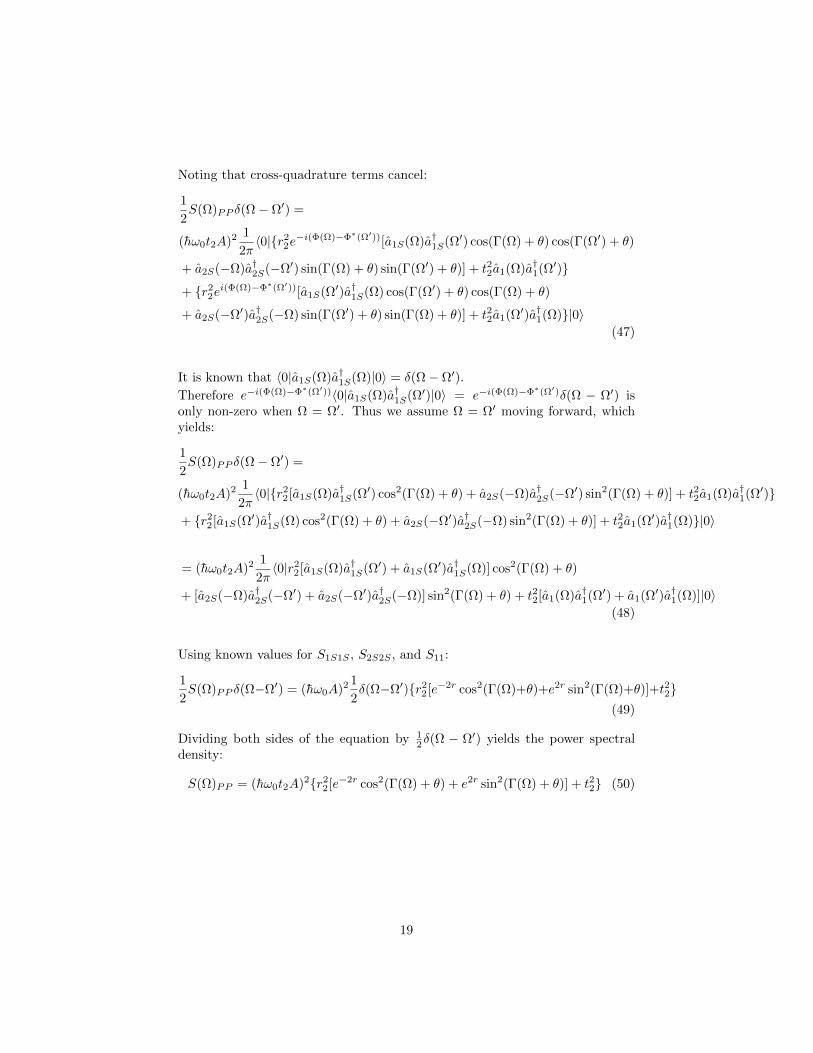
Noting that cross-quadrature terms cancel:
1
2S(Ω)PP δ(Ω− Ω′) =
(hω0t2A)2 1
2π〈0|r2
2e−i(Φ(Ω)−Φ∗(Ω′))[a1S(Ω)a†1S(Ω′) cos(Γ(Ω) + θ) cos(Γ(Ω′) + θ)
+ a2S(−Ω)a†2S(−Ω′) sin(Γ(Ω) + θ) sin(Γ(Ω′) + θ)] + t22a1(Ω)a†1(Ω′)
+ r22ei(Φ(Ω)−Φ∗(Ω′))[a1S(Ω′)a†1S(Ω) cos(Γ(Ω′) + θ) cos(Γ(Ω) + θ)
+ a2S(−Ω′)a†2S(−Ω) sin(Γ(Ω′) + θ) sin(Γ(Ω) + θ)] + t22a1(Ω′)a†1(Ω)|0〉(47)
It is known that 〈0|a1S(Ω)a†1S(Ω)|0〉 = δ(Ω− Ω′).
Therefore e−i(Φ(Ω)−Φ∗(Ω′))〈0|a1S(Ω)a†1S(Ω′)|0〉 = e−i(Φ(Ω)−Φ∗(Ω′)δ(Ω − Ω′) isonly non-zero when Ω = Ω′. Thus we assume Ω = Ω′ moving forward, whichyields:
1
2S(Ω)PP δ(Ω− Ω′) =
(hω0t2A)2 1
2π〈0|r2
2[a1S(Ω)a†1S(Ω′) cos2(Γ(Ω) + θ) + a2S(−Ω)a†2S(−Ω′) sin2(Γ(Ω) + θ)] + t22a1(Ω)a†1(Ω′)
+ r22[a1S(Ω′)a†1S(Ω) cos2(Γ(Ω) + θ) + a2S(−Ω′)a†2S(−Ω) sin2(Γ(Ω) + θ)] + t22a1(Ω′)a†1(Ω)|0〉
= (hω0t2A)2 1
2π〈0|r2
2[a1S(Ω)a†1S(Ω′) + a1S(Ω′)a†1S(Ω)] cos2(Γ(Ω) + θ)
+ [a2S(−Ω)a†2S(−Ω′) + a2S(−Ω′)a†2S(−Ω)] sin2(Γ(Ω) + θ) + t22[a1(Ω)a†1(Ω′) + a1(Ω′)a†1(Ω)]|0〉(48)
Using known values for S1S1S , S2S2S , and S11:
1
2S(Ω)PP δ(Ω−Ω′) = (hω0A)2 1
2δ(Ω−Ω′)r2
2[e−2r cos2(Γ(Ω)+θ)+e2r sin2(Γ(Ω)+θ)]+t22(49)
Dividing both sides of the equation by 12δ(Ω − Ω′) yields the power spectral
density:
S(Ω)PP = (hω0t2A)2r22[e−2r cos2(Γ(Ω) + θ) + e2r sin2(Γ(Ω) + θ)] + t22 (50)
19
6 Multi-Mode Coherent Light and Squeezed Lightwith a Filter Cavity
6.1 Calculating Power
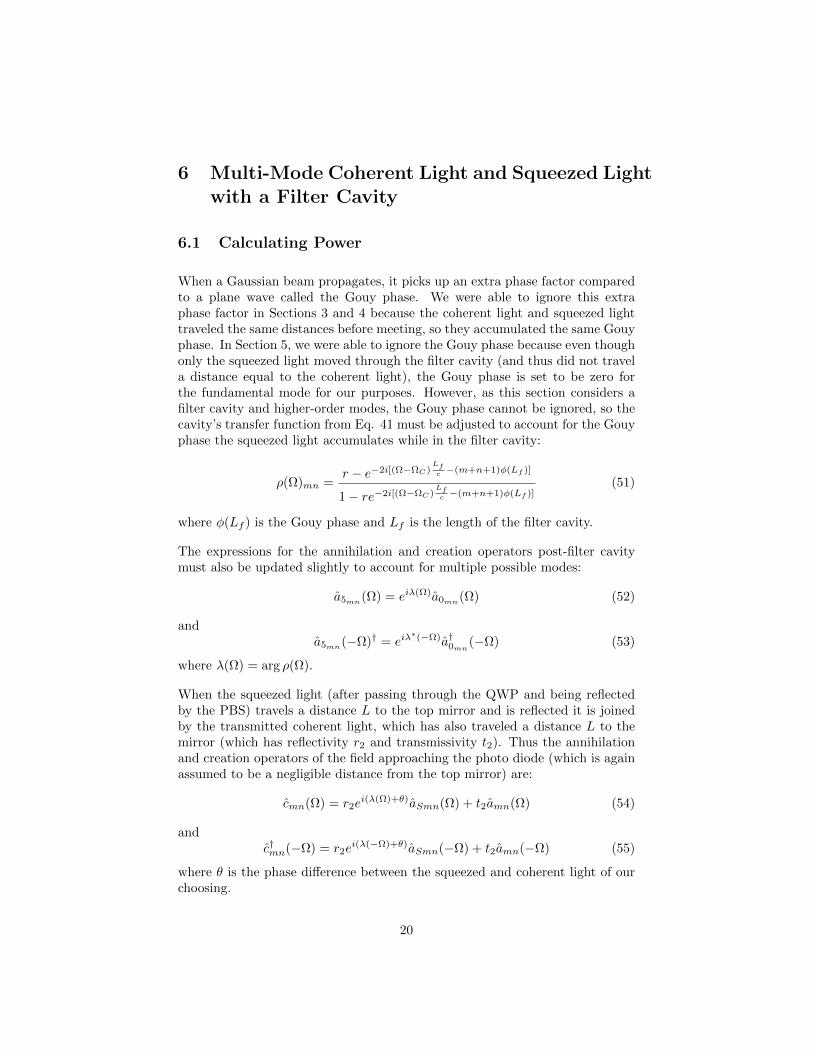
When a Gaussian beam propagates, it picks up an extra phase factor comparedto a plane wave called the Gouy phase. We were able to ignore this extraphase factor in Sections 3 and 4 because the coherent light and squeezed lighttraveled the same distances before meeting, so they accumulated the same Gouyphase. In Section 5, we were able to ignore the Gouy phase because even thoughonly the squeezed light moved through the filter cavity (and thus did not travela distance equal to the coherent light), the Gouy phase is set to be zero forthe fundamental mode for our purposes. However, as this section considers afilter cavity and higher-order modes, the Gouy phase cannot be ignored, so thecavity’s transfer function from Eq. 41 must be adjusted to account for the Gouyphase the squeezed light accumulates while in the filter cavity:
ρ(Ω)mn =r − e−2i[(Ω−ΩC)
Lfc −(m+n+1)φ(Lf )]
1− re−2i[(Ω−ΩC)Lfc −(m+n+1)φ(Lf )]
(51)
where φ(Lf ) is the Gouy phase and Lf is the length of the filter cavity.
The expressions for the annihilation and creation operators post-filter cavitymust also be updated slightly to account for multiple possible modes:
a5mn(Ω) = eiλ(Ω)a0mn
(Ω) (52)
anda5mn
(−Ω)† = eiλ∗(−Ω)a†0mn
(−Ω) (53)
where λ(Ω) = arg ρ(Ω).
When the squeezed light (after passing through the QWP and being reflectedby the PBS) travels a distance L to the top mirror and is reflected it is joinedby the transmitted coherent light, which has also traveled a distance L to themirror (which has reflectivity r2 and transmissivity t2). Thus the annihilationand creation operators of the field approaching the photo diode (which is againassumed to be a negligible distance from the top mirror) are:
cmn(Ω) = r2ei(λ(Ω)+θ)aSmn(Ω) + t2amn(Ω) (54)
andc†mn(−Ω) = r2e
i(λ(−Ω)+θ)aSmn(−Ω) + t2amn(−Ω) (55)
where θ is the phase difference between the squeezed and coherent light of ourchoosing.
20
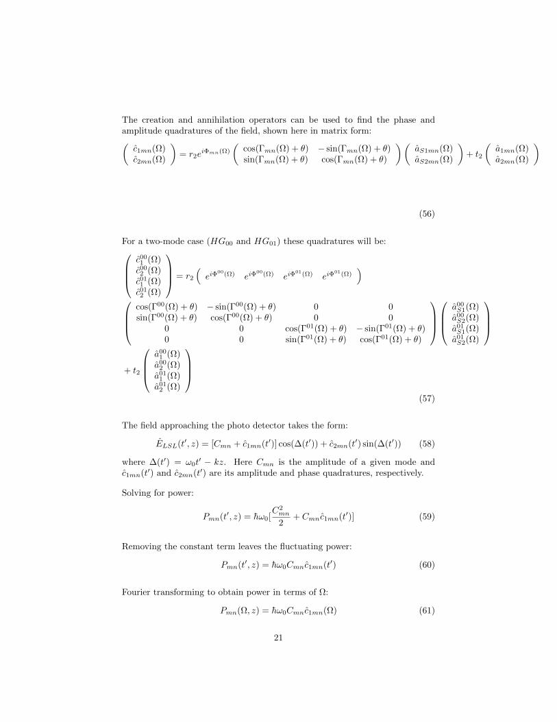
The creation and annihilation operators can be used to find the phase andamplitude quadratures of the field, shown here in matrix form:(c1mn(Ω)c2mn(Ω)
)= r2e
iΦmn(Ω)
(cos(Γmn(Ω) + θ) − sin(Γmn(Ω) + θ)sin(Γmn(Ω) + θ) cos(Γmn(Ω) + θ)
)(aS1mn(Ω)aS2mn(Ω)
)+ t2
(a1mn(Ω)a2mn(Ω)
)
(56)
For a two-mode case (HG00 and HG01) these quadratures will be:c001 (Ω)c002 (Ω)c011 (Ω)c012 (Ω)
= r2
(eiΦ
00(Ω) eiΦ00(Ω) eiΦ
01(Ω) eiΦ01(Ω)
)
cos(Γ00(Ω) + θ) − sin(Γ00(Ω) + θ) 0 0sin(Γ00(Ω) + θ) cos(Γ00(Ω) + θ) 0 0
0 0 cos(Γ01(Ω) + θ) − sin(Γ01(Ω) + θ)0 0 sin(Γ01(Ω) + θ) cos(Γ01(Ω) + θ)
a00S1(Ω)a00S2(Ω)a01S1(Ω)a01S2(Ω)
+ t2
a00
1 (Ω)a00
2 (Ω)a01
1 (Ω)a01
2 (Ω)
(57)
The field approaching the photo detector takes the form:
ELSL(t′, z) = [Cmn + c1mn(t′)] cos(∆(t′)) + c2mn(t′) sin(∆(t′)) (58)
where ∆(t′) = ω0t′ − kz. Here Cmn is the amplitude of a given mode and
c1mn(t′) and c2mn(t′) are its amplitude and phase quadratures, respectively.
Solving for power:
Pmn(t′, z) = hω0[C2mn
2+ Cmnc1mn(t′)] (59)
Removing the constant term leaves the fluctuating power:
Pmn(t′, z) = hω0Cmnc1mn(t′) (60)
Fourier transforming to obtain power in terms of Ω:
Pmn(Ω, z) = hω0Cmnc1mn(Ω) (61)
21
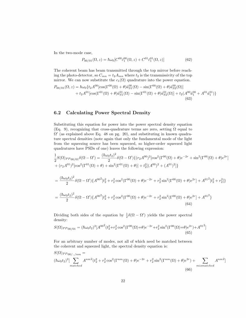
In the two-mode case,
P00/01(Ω, z) = hω0[C00c001 (Ω, z) + C01c01
1 (Ω, z)] (62)
The coherent beam has beam transmitted through the top mirror before reach-ing the photo-detector, so Cmn = t2Amn where t2 is the transmissivity of the topmirror. We can now substitute the c1(Ω) quadrature into the power equation.
P00/01(Ω, z) = hω0t2A00[cos(Γ00(Ω) + θ)a00S1(Ω)− sin(Γ00(Ω) + θ)a00
S2(Ω)]
+ t2A01[cos(Γ01(Ω) + θ)a01
S1(Ω)− sin(Γ01(Ω) + θ)a01S2(Ω)] + t2(A00a00
1 +A01a011 )
(63)
6.2 Calculating Power Spectral Density
Substituting this equation for power into the power spectral density equation(Eq. 9), recognizing that cross-quadrature terms are zero, setting Ω equal toΩ′ (as explained above Eq. 48 on pg. 20), and substituting in known quadra-ture spectral densities (note again that only the fundamental mode of the lightfrom the squeezing source has been squeezed, so higher-order squeezed lightquadratures have PSDs of one) leaves the following expression:
1
2S(Ω)PP 00/01δ(Ω− Ω′) =
(hω0t2)2
2δ(Ω− Ω′)(r2A
00)2[cos2(Γ00(Ω) + θ)e−2r + sin2(Γ00(Ω) + θ)e2r]
+ (r2A01)2[cos2(Γ01(Ω) + θ) + sin2(Γ01(Ω) + θ)] + t22[(A00)2 + (A01)2]
=(hω0t2)2
2δ(Ω− Ω′)A002
[t22 + r22 cos2(Γ00(Ω) + θ)e−2r + r2
2 sin2(Γ00(Ω) + θ)e2r] +A012[t22 + r2
2]
=(hω0t2)2
2δ(Ω− Ω′)A002
[t22 + r22 cos2(Γ00(Ω) + θ)e−2r + r2
2 sin2(Γ00(Ω) + θ)e2r] +A012(64)
Dividing both sides of the equation by 12δ(Ω − Ω′) yields the power spectral
density:
S(Ω)PP 00/01 = (hω0t2)2[A002(t22+r2
2 cos2(Γ00(Ω)+θ)e−2r+r22 sin2(Γ00(Ω)+θ)e2r)+A012
]
(65)
For an arbitrary number of modes, not all of which need be matched betweenthe coherent and squeezed light, the spectral density equation is:
S(Ω)PP 00/../nm =
(hω0t2)2[∑
matched
Anm2(t22 + r22 cos2(Γnm(Ω) + θ)e−2r + r2
2 sin2(Γnm(Ω) + θ)e2r) +∑
mismatched
Anm2]
(66)
22
6.3 Comparing Analytical Results to FINESSE Simula-tion
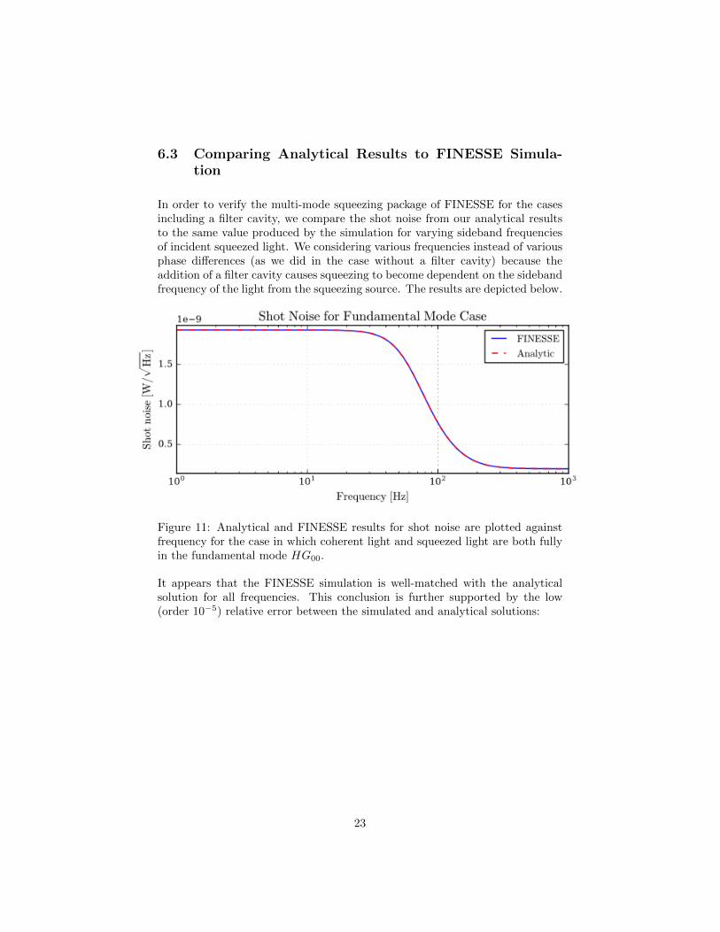
In order to verify the multi-mode squeezing package of FINESSE for the casesincluding a filter cavity, we compare the shot noise from our analytical resultsto the same value produced by the simulation for varying sideband frequenciesof incident squeezed light. We considering various frequencies instead of variousphase differences (as we did in the case without a filter cavity) because theaddition of a filter cavity causes squeezing to become dependent on the sidebandfrequency of the light from the squeezing source. The results are depicted below.
Figure 11: Analytical and FINESSE results for shot noise are plotted againstfrequency for the case in which coherent light and squeezed light are both fullyin the fundamental mode HG00.
It appears that the FINESSE simulation is well-matched with the analyticalsolution for all frequencies. This conclusion is further supported by the low(order 10−5) relative error between the simulated and analytical solutions:
23
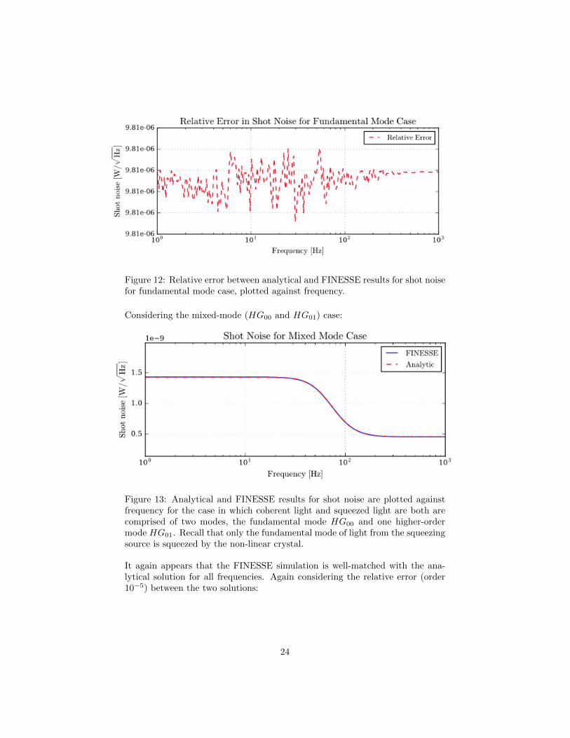
Figure 12: Relative error between analytical and FINESSE results for shot noisefor fundamental mode case, plotted against frequency.
Considering the mixed-mode (HG00 and HG01) case:
Figure 13: Analytical and FINESSE results for shot noise are plotted againstfrequency for the case in which coherent light and squeezed light are both arecomprised of two modes, the fundamental mode HG00 and one higher-ordermode HG01. Recall that only the fundamental mode of light from the squeezingsource is squeezed by the non-linear crystal.
It again appears that the FINESSE simulation is well-matched with the ana-lytical solution for all frequencies. Again considering the relative error (order10−5) between the two solutions:
24
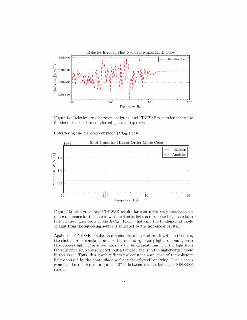
Figure 14: Relative error between analytical and FINESSE results for shot noisefor the mixed-mode case, plotted against frequency.
Considering the higher-order mode (HG01) case:
Figure 15: Analytical and FINESSE results for shot noise are plotted againstphase difference for the case in which coherent light and squeezed light are bothfully in the higher-order mode HG01. Recall that only the fundamental modeof light from the squeezing source is squeezed by the non-linear crystal.
Again, the FINESSE simulation matches the analytical result well. In this case,the shot noise is constant because there is no squeezing light combining withthe coherent light. This is because only the fundamental mode of the light fromthe squeezing source is squeezed, but all of the light is in the higher-order modein this case. Thus, this graph reflects the constant amplitude of the coherentlight observed by the photo diode without the effect of squeezing. Let us againexamine the relative error (order 10−5) between the analytic and FINESSEresults:
25
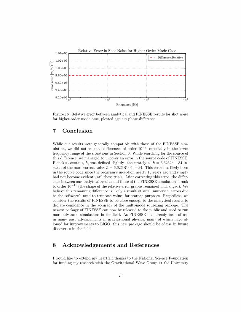
Figure 16: Relative error between analytical and FINESSE results for shot noisefor higher-order mode case, plotted against phase difference.
7 Conclusion
While our results were generally compatible with those of the FINESSE sim-ulation, we did notice small differences of order 10−5, especially in the lowerfrequency range of the situations in Section 6. While searching for the source ofthis difference, we managed to uncover an error in the source code of FINESSE.Planck’s constant, h, was defined slightly inaccurately as h = 6.6262e − 34 in-stead of the more correct value h = 6.62607004e−34. This error has likely beenin the source code since the program’s inception nearly 15 years ago and simplyhad not become evident until these trials. After correcting this error, the differ-ence between our analytical results and those of the FINESSE simulation shrankto order 10−11 (the shape of the relative error graphs remained unchanged). Webelieve this remaining difference is likely a result of small numerical errors dueto the software’s need to truncate values for storage purposes. Regardless, weconsider the results of FINESSE to be close enough to the analytical results todeclare confidence in the accuracy of the multi-mode squeezing package. Thenewest package of FINESSE can now be released to the public and used to runmore advanced simulations in the field. As FINESSE has already been of usein many past advancements in gravitational physics, many of which have al-lowed for improvements to LIGO, this new package should be of use in futurediscoveries in the field.
8 Acknowledgements and References
I would like to extend my heartfelt thanks to the National Science Foundationfor funding my research with the Gravitational Wave Group at the University
26
of Birmingham and to the Gravitational Physics IREU at the University ofFlorida for selecting me and placing me in such a wonderful environment. Inaddition, I would like to thank the University of Birmingham, the Departmentof Physics and Astronomy, and the Gravitational Wave Group for giving methe opportunity to work on this project. Thirdly, I extend my thanks to mysupervisors Dr. Haixing Miao and Dr. Andreas Freise and mentor Daniel Toyrafor their patience and guidance. Finally, I would like to recognize and thankmy teammates Song Shicong and Alex Wormwald for their work on this projectwith me and their friendship during my months abroad.
This project and this summer abroad have been incredible experiences for whichI am so grateful. I have learned so much, both about this field and about myself,and am so thankful to have had the opportunity to do so.
My references are as follows:
Chelkowski, Simon. Squeezed Light and Laser Interferometric GravitationalWave Detectors. Thesis. Hannover, University, Diss, 1976. Wilhelm LeibnizUniversita t Hannover: Hannover, n.d. Print.
Freise, Andreas, Kenneth A. Strain, Daniel Brown, and Charlotte Bond. ”In-terferometer Techniques for Gravitational-Wave Detection.” Living Reviews inRelativity Living Rev. Relativity 13 (2010): n. pag. Web.
”Random Processes.” Applications of Classical Physics. Caltech: Pasadena,2012. 1-56. Print.
Y. Chen and H. Miao. Quantum Theory of Laser-Interferometer GW Detectors.Advanced Gravitational Wave Detectors Ed. D. G. Blair, L. Ju, C. Zhao, andE. J. Howell Cambridge University Press: Cambridge, 2012. 1-23. Print.
27