Embed Size (px)
Citation preview

Modern Applied Science; Vol. 14, No. 11; 2020 ISSN 1913-1844 E-ISSN 1913-1852
Published by Canadian Center of Science and Education
19
Multi-Method END Study in the Search for 'Defects' in an Aeronautical Radar Element
Gaston Sanglier1, Jose Miguel2, Jose Antonio Penaranda2 & y Gabriel Del Ojo2
1 Central Laboratory of Remote Sensing. Instituto Nacional de Técnica Aeroespacial (INTA), Crta. Ajálvir Km.4, 28850 Torrejón de Ardoz, Madrid, Spain 2 Non-Destructive Testing Laboratory. Instituto Nacional de Técnica Aeroespacial (INTA), Crta. Ajálvir Km.4, 28850 Torrejón de Ardoz, Madrid, Spain Correspondence: Gaston Sanglier, Instituto Nacional de Técnica Aeroespacial (INTA), Crta. Ajálvir Km.4, 28850 Torrejón de Ardoz, Madrid, Spain. Received: September 18, 2020 Accepted: October 26, 2020 Online Published: October 27, 2020 doi:10.5539/mas.v14n11p19 URL: https://doi.org/10.5539/mas.v14n11p19 Abstract Non-Destructive Testing (NDT) has gone from being a simple laboratory curiosity to an indispensable tool in the industry to determine the level of quality achieved in its products. The new concepts of Integrated Manufacturing (CIM) bring a more universal concept of quality compared to the past philosophy based on Quality Control as a group specialized in checking whether production works within certain specifications. Even so, NDTs have not lost interest, but have seen their interest increased due to automated inspection techniques. It has become a contribution to the structuring of quality as it allows to move from purely empirical criteria to other more objective and that constitute the link between design and evaluation (Ramirez et al, 1996). The work presented, although it does not propose new methods or techniques of NDT, has the interest of converging into a single object five conventional methods each of which provides partial information about their quality of manufacture and must synthesize the results in order to evaluate it. Furthermore, it shows a situation of the application of NDT in which these must be applied in the absence of reference standards, as they do not exist. This peculiar situation is completely different from the usual situation in the use of NDT in the industry, both in manufacturing processes and in maintenance inspections. Keywords: non-destructive testing, ultrasound, thermography, radiography, acoustic, ultraviolet, visual 1. Introduction In the scientific tradition, observation plays a major role. When the observed phenomenon has been provoked, you have the experiment. Through the experiment, the behavior of Nature is verified under controlled conditions in order to discover regularities that can be described in a logical way and be enunciated as laws. In technology, it is not so much important to discover natural laws as to apply them to questions of immediate utility, and so the experiment shortens its scope and becomes an experiment, in such a way that it can be indicated that an experiment is a technological experiment (Sanglier et al., 2020). According to the testing of materials, they can be divided into three categories:
- Functional tests - Destructive Testing - Non-Destructive Testing
This work will refer to the Non-Destructive Tests that should be adapted to the requirements of the sample to avoid its deterioration. This is achieved by resorting to those physical characteristics of the material that are technologically significant, and as these can be very varied (density, thermal conductivity, electromagnetic absorbance, refractive index, crystalline structure, etc.) hence the number of Non-Destructive Tests is potentially large and their basis diverse. From the point of view of their fundamentals, Non-Destructive Tests are mainly based on the application of one or several of the following physical phenomena

mas.ccsenet.org Modern Applied Science Vol. 14, No. 11; 2020
20
- Electromagnetic waves, including phenomena based on the electrical and/or magnetic properties of the samples - Elastic or acoustic waves - Subatomic particle emission - Other phenomena such as capillarity, watertightness, absorption, etc.
In terms of applications, Non-Destructive Testing methods cover three broad areas: - Defectology: detection of heterogeneities, discontinuities and impurities; evaluation of corrosion and deterioration by environmental agents; determination of stresses; detection of leaks; defects in moving machinery; hot spots. - Material characteristics: chemical, structural, mechanical and technological characteristics; physical (elastic, electrical and electromagnetic); heat transfer and isothermal trace. - Metrology: thickness control; one-sided thickness measurement; coating thickness measurement; filling levels. The problem that appears with the application of the different NDT techniques is that it is not very well known since it depends on many factors, which will be the most suitable technique for each type of inspection. For example, in non-destructive testing without contact and in the astronautical field, very high demands are made. The materials used in this very specialized branch of engineering must not only have very high quality levels, but also the tests that require their verification must be such that they do not produce any type of contamination. This severe requirement eliminates many traditional techniques and even some methods. This is the case, for example, with penetrating liquids, magnetic particles or contact ultrasound. In fact, only visual inspection or radiography meets these requirements and, under certain operating conditions, currents induced by mentioning traditional methods. Stimulated by this need, some methods have developed very sophisticated specific techniques that allow physical contact to be replaced by optical contact (surface holography, holographic interferometry, infrared thermography). For example, it is possible to stimulate the generation of ultrasounds in a material by means of laser 'impact' and 'read' by this same means the fine vibrations generated. The main interest of this work is that it is a rare example of the application in a single object (piece) of a considerable number of non-destructive tests. Nor is´t common that this is done in the absence of specifications, both the procedure for conducting the tests and acceptance-rejection criteria (ASM, 1989; Barbero, 1999). This is unusual in the industrial field where the rule is to follow an operating procedure specification, specially prepared for each specific case, based on solvent standards and containing clear and unequivocal acceptance-rejection criteria. On the other hand, most often the tests to be performed on each specimen are not numerous for well-defined products. Two or three is normal; sometimes just one. And in any case related, if not in their physical basis, then in their purpose of trying to highlight certain well-determined types of discontinuities and not others (Baker, Jones & Callinan, 1985; Bishop, 1985). However, when it comes to establishing the degree of confidence that we deserve in the behavior in service of a newly designed object, made perhaps of a rare material of which there are few examples, perhaps only one, and which is also going to serve an application of which there is no direct previous experience, it is clear that the doctrine commonly followed in the industry is not useful (Heru et al., 1997; Scarponi & Briotti, 2000; Miyano et al., 1994). In these cases, not uncommon in applied research, the only possible guide is a judicious theoretical analysis of the service conditions and the behavior of the material under those conditions and according to a concrete design. The result is a theoretical "model", if you want "virtual", which only has the value of being a reasonable basis for approaching the real behavior of the object (Huang et al., 1998; Kapranos & Priestner, 1987). As this is insufficient, it will be necessary to make representative samples with controlled discontinuities and even better, a prototype to test it under conditions qualitatively similar to those of service and quantitatively more severe, being advisable to prolong the tests until the failure occurs. Only from the experience gathered in such tests and from the previous theoretical analyses is it possible to extract the essential information to draw up quality specifications and to establish reliable acceptance-rejection criteria. 2. Methods For some time now, INTA has been developing a radar system for stereometric surveying of the relief of large areas of land. As the resolution is given by the opening of the system and this depends on the size of the antenna, to achieve high resolutions would be necessary very large antennas. As, on the other hand, the surveys are

mas.ccsen
intended board. Thdistant shaperture developedTo carry to electrobehind wSince theaerodynaincludingonly threstandardsThe matepanels. T"skins", eafter curinfiberglassAlthoughjoints thanecessary
2.1 Tests Non-destbut exclusuch discinclusionmethods ImieliÈskBalageas,tests in teestimatesthey repo
net.org
to be performhese drawbachots during fliequivalent tod by INTA (Sout the functi
omagnetic wawhich the radar
e "radome", amic pressuresg non-destructee specially ds applicable toerial of the radThe sandwich each consistinng of 0.4 mms fabric. Evenh the shape of at affect the cy holes to fix i
tructive tests ausively to highcontinuities arns of foreign m
as possible, ka et al., 2004, 2003; Davidest tubes mads, which will nort discontinu
med from an cks can be avight that meet o the distanceSanglier et al., ional tests of
aves in the orr is located. or "radar do
s, and its failutive ones, to e
designed pieceo this type of odome, shown is manufactu
ng of two laym. Each side pantually, it can the piece is re
continuity of tit to the door f
Figure 1
applied to thehlight the presre not well chamaterials, etc.)according to 4, Ochelski, 2d & Hsu, 2006de according tnot be analyze
uities of differ
Mod
aircraft in fligvoided by wha
certain phasee between the2003; Balagethis system, ader of frequen
ome", must bure could havestimate whethes have been object can be rin figure 1, c
ured from a 5 ers of fiberglanel is 1.6 mmbe painted w
elatively simpthe whole. Thframe of the a
. General view
radome are nsence of possiaracterized an) and affect bthe appropria
2004; Padman6). The colleco the manufaed in this worrent nature, co
dern Applied Sc
21
ght, such anteat is known ae matching cone shots. This
eas, 2005). a protective coencies used, w
be subjected ve serious conther its quality
manufacturedreferred to.onsists of a cmm thick rig
lass fabric (Gm thick resultinwith an organicple, the formathis, on the otaircraft it repla
w of the piece
not intended tible discontin
nd can be veryoth the core aate applicationabhan & Kisction of such acturing criterirk. Naturally, ompleting eac
cience
ennas would bas "synthetic nditions, so th
s is "grosso m
over or "radomwhich replaces
to mechanicnsequences, iy is sufficient d, it is obviou entral sandwigid organic fo380T2/1990S
ng from stackc lacquer trantion of the strother hand, hasaces.
e under study:
to verify dimenuities that couy varied (delaand the "skinson techniques shore, 1995; Minformation sia, and valuedthe methods u
ch other's resu
be virtually imaperture" wh
hat the systemmodo", the sy
me" has been s one of the d
cal stresses dt is necessaryto guarantee
us that no ex
ch structure aoam core (rohS) and resin ging eight layesparent to eleongest curvatus an aluminum
Radomo
ensions or chauld affect its bminations and
s", it´s advisab(Barbero, 19
Maldague, 200hould be cont
d according toused may be "ults, or "conc
Vol. 14, N
mpossible to hich consists om behaves as i
ynthetic aper
n developed, trdoors of the t
due to vibray through var
that it will nxisting specifi
and two monohacell 31) glugiving a totalers of resin-imectromagnetic ures has forcem alloy frame
aracterize the behavior in sd detachmentsble to resort to999; Gray et 01; Krapez, Ttrasted with do the design c"complementacurrent" if two
No. 11; 2020
mount on of making f it had an ture radar
ransparent test plane,
ations and rious tests, ot fail. As cations or
olithic side ued to two
thickness mpregnated
radiation. d cuts and e with the
materials, ervice. As s, cavities, o as many al., 1995;
Taillade & destructive calculation ary" when o or more

mas.ccsenet.org Modern Applied Science Vol. 14, No. 11; 2020
22
tests report the existence of the same discontinuity (Potel et al., 1998; Clauser, 1952; Rosethal & Trolinger, 1995; Globe, 1979; Bales & Bishop, 1994; David, Hsu, Barnard & Daniel, 2004). The applied essays (the basis of which is given as known) are the following:
- Visual. - Radiographic. - Ultrasound. - Sonic. - Thermography. - Ultraviolet.
Penetrating liquids and in general any technique that involves contaminating the material with a coupling fluid were discarded (Wan et al., 2016; Silk, 1982). The results achieved are described below, with emphasis on a comparison of those provided by one or another method. 2.2 Operating Conditions Although depending on the method applied and the area of the parts where the specific operating conditions are applied, as a guideline we summarize below those that can be considered typical:
- Visual: Light levels between 500 and 1000 lux. Observation with the naked eye or with low power magnifiers (< 10 d). - Radiographic: X-rays from 40 to 45 KV. Exposures of 7 to 8 mA x min. without filters. Type I film without ASTM. Without reinforcement sheets. Focus-film distance irrelevant (900 mm was used). Focus of 0,8 x 0,8 mm. - Ultrasound: Transmission by total immersion. Frequency: 1 MHz. - Sonic: Scanning with continuous Lamb wave between 2.5 and 70 KHz. - Thermography: Spectral range from 7.5 to 13 µm. FOV: 24º. - Ultraviolet A: Wave length: 366 nm. Energetic illumination: 10 w/m2.
2.3 Discontinuities Given the nature of the material, the usual designation of discontinuities may have a different meaning than the common one in NDT, which normally comes from those found in metallic materials. Therefore, an attempt will be made to introduce descriptive names for most discontinuities (Mouritz, Townsend & Shah Khan, 2000; Mitrevski, Marshall & Thomson, 2006; Hasiotis, Badoggiannis & Tsouvalis, 2007). On the other hand, the visual definition of certain discontinuities is affected by the translucent nature of the material which can make its appearance diffuse. Finally, it´s necessary to note the difficulty of graphic reproduction of a good part of the images obtained, so that those included in this work give a very poor idea of the originals (Lawson & Sabey, 1970). 3. Results 3.1 Test Pieces In order to test the effectiveness of different methods in detecting flat discontinuities, a master specimen was used in which different artificial discontinuities were introduced, such as peel-offs between "skin" and core on both sides of the specimen and core breaks in the central plane of the specimen. First, the specimen was inspected with ultrasound transmission in total immersion. The image shown in figure 2 was obtained, where it can be seen that all the discontinuities (dark areas) existing in the upper and lower bands of the test tube have been detected, as well as other discontinuities, located in the central band of the test tube, which were not suspected. In the image you can see four holes (light circles) located in the corners, around which there are also areas with detachments.

mas.ccsen
FUsing thewere obtaexaminatof the cenas a darkagreemenareas (arrultrasonicthat couldAs we hareason beinsulationsince the
Figure
Based on1987; Briin emissiside of thoperatingand receiadvantageabsence oopposite detection the discoFigure 4 signal obt
net.org
igure 2. Image transmissionained, which ction of the leftnter line (arrok rectangular nt between ulrows b) of thec test providedd not be obtainave just seen,eing the low cn of the core, capacity to tr
e 3. Thermogran the previous igss, 1985; Poon-reception
he radome is ag frequency, itiver probes pes of the techof contact of direction that
n of false positntinuities preshows the signtained in a go
ge of a specimen thermographcorrespond to t image, it canow a). This inarea (arrow a
ltrasonic and e images reprd a series of ined by thermo, thermographontrast of the which means
ansmit heat is
aphic image oparagraph, w
ollock, 1998) ton the same s
able to reveal dt does not reqprovided withhnique are: thsome of the pt when in the tives (Ramirezsent in the spnals obtained od area, while
Mod
en with disconhy technique (the upper (lef
n be seen that odication correa) on the ultrathermographiesented in figndications duography. hy is not very
discontinuities that heat tras very similar
of the upper (lwe proceeded t
that works byside of the pidiscontinuitiesquire any couph a Teflon sohe ease of adjprobes with thpresence of a
z et al., 1996)pecimen (uppe
in one of the e on the left si
dern Applied Sc
23
ntinuities obta(Sanglier et alft image) and only a light co
esponds to a pasonic image ic methods is gure 2 and onue to discontin
y effective in es obtained inansmission is in the core an
eft) and lowerto test a sonic
y scanning, betiece. This techs located on bpling means, ole that facilidjustment fromhe piece, the a discontinuit). Operating frer, lower, anddiscontinuitieide you can se
cience
ained by transl., 2020; Cielolower (right iolor indicationpeeling off at
(figure 2). Ingreater, as cthe right side
nuities in the c
detecting flatn thermograph
hardly affectnd in the take-o
r (right) parts c technique (Stween 2 and 7hnique has thboth sides of thso it is a dry
itates the dispm appropriatesignal obtain
ty (the signal from one side,d central bandes. On the righee the signal w
mission ultraso et al., 1987)mage) bands on is visible at the junction "n the lower ban be seen bye of figure 3. central band o
t discontinuitihic images, theed by the exioff.
of the specimpanner, 1974;
70 KHz, with e advantage the radome. Mcontact techn
placement thr test pieces aed (becomes increases in s this techniqus) that the ult
ht side of the iwhen a discont
Vol. 14, N
sonic inspectio), the images iof the patternthe top, just t
"skin"-core anband of the py comparing On the other
of the pattern
ies in this mae high power oistence of the
men shown in f; Dunegan & continuous L
that operatingMoreover, due nique; being trough the pieand the fact tsmaller) evolsize), which a
ue was able totrasounds hadimage is repretinuity is pres
No. 11; 2020
on in figure 3 . From the o the right nd appears attern, the the lower
r hand, the (arrows c)
aterial, the of thermal take-offs,
figure 2 Tetelman, amb wave from one to the low he emitter ece. Other that in the lves in the avoids the
o detect all d revealed. esented the ent.

mas.ccsen
Althoughvolumetricomparedcavities wThermogcontrast o3.2 Test oThey werobtainingdetect flaone of thmethods, and someaffecting occasionareasons mpainted, vAlso incluis especiasurface ob
FiguFigure 6aof the pie(arrow a, break in tThe disco
net.org
Figurh it is not feasiic, it can be d to "skins" twith a diameraphy behaveobtained in thion Parts re made main
g the results that discontinuithose available
it is clear thae by only one
the fiberglasally by thermomentioned in visually (Craikuded is an imally useful fobserved (Rose
ure 5. Image oa shows an X-ece had been figure 6a) bethe fabric on tontinuities ind
re 4. Signals oible for X-rayrevealed by
that the existeeter of the ores somewhat is type of mat
nly combininghat are specif
ties in the sane that can detat only some de. In general, ss fabric (breography. On tthe previous
k & Vernon, 1age obtained b
or detecting centhal & Troli
obtained by U-ray (Bermúde
n visually deteetween the twothe outside thadicated by arro
Mod
obtained with s to detect flatX-ray. In thi
ence or not order of 50% better in the
erial is low.
g the visual, rfied in the figdwich, since, tect them relidiscontinuities
volumetric deaks, splices, the other handsection, are
1941; Von Heby means of Uertain types oinger, 1995; S
UVA. In light cez, 1963; Sproected (see phoo white circleat is painted, sows a and b di
dern Applied Sc
24
a sonic technit discontinuitiis case the nu
of a nucleus dof the thickn
e case of volu
radiographic, tgures that wilalthough in p
iably. From ths are detecteddiscontinuities
folds, etc.) d, the discontionly percepti
elmholtz, 1963UVA (figure 5of inclusions Steton & Ferra
color, some inoull, 1946) ofotograph in f
es. There is a vsince this is noid not provide
cience
ique for detecies, it can be tucleus is so does not influness of the cumetric disco
thermographill be shown lprinciple, it dohe analysis o
d by all three ms, such as cavare well seeninuities that aible by therm3; Reynolds, 15) that demonsand the irreg
aro, 1993; Erf
nclusions are sf an area wherfigure 6c). Thvertical disconot visually obse indications w
ting discontinhought that wlight and abs
uence the radicore do not pontinuities in
c and sonic (Later. The sonoes not providof the results methods; othevities or resinn visually anffect the core ography and,
1996). strates how thular distributi
f, 1974).
shown in the fre a break in thhis breakage gntinuity (arrowserved on the when inspected
Vol. 14, N
nuities when the discosorbs so littleiographic imaprovide any i
the core, bu
Lamb waves)nic method wade images, it iof the three
ers by only twn pockets, or nd by radiogr of the materi when the pi
his band of theion of the res
form of a filamhe "skin" of thgives a clear w b), probablinside. d by thermogr
No. 11; 2020
ontinuity is e radiation age. Thus, indication.
ut also the
) methods, as used to is the only remaining
wo of them anomalies raphy and ial, for the ece is not
e spectrum sin on the
ment he interior indication
ly due to a
raphy.

mas.ccsen
Arrows cwhose sh
In the theaxis of thAlthoughprocess it
net.org
c indicate an ahape coincides
Figudiscin fi
ermography thhe radome andh the reason fotself.
Figure 6d
area with irregs exactly with
Figure 6a
ure 6b. Radiogcontinuity marigure 6a here is a vert
d has no relatioor the existenc
. Thermograp
Mod
gularities in ththe indication
a. X-ray of an
graphic detail rked with the a
ical indicationonship with th
ce of this indic
hy of a zone p
dern Applied Sc
25
he resin distribn shown in the
area showing
of arrow a
n (arrow d) inhe radiographcation is unkn
partially coinc
cience
bution (probabe thermograph
g various disco
Figure 6c marked w
n the central aic indication i
nown to us, it i
cident with the
bly additionalhic image in fi
ontinuities
c. Visual detaiwith the arrow
area that runsindicated by this clear that it
e one shown in
Vol. 14, N
l resin has beeigure 6d.
il of the disconb in figure 6a
s along the lothe arrow b in is in the manu
in figure 6a
No. 11; 2020
en added),
ntinuity a
ngitudinal figure 6a.
ufacturing
mas.ccsen
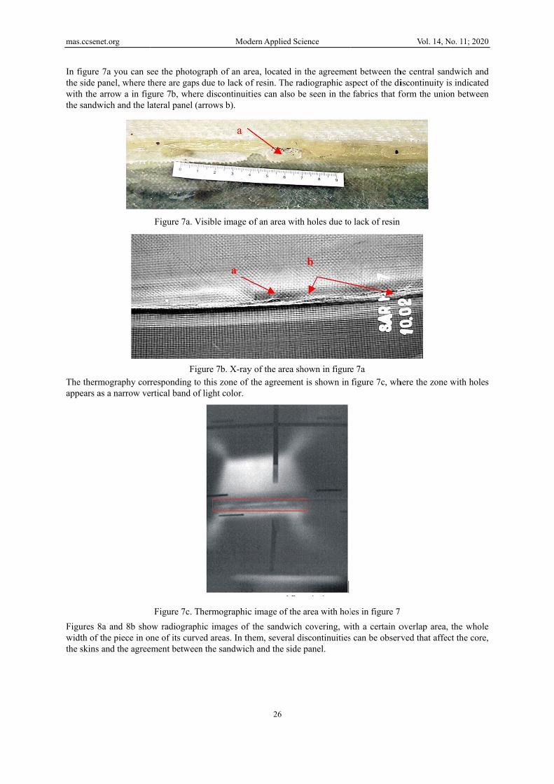
In figure the side pwith the athe sandw
The thermappears a
Figures 8width of tthe skins
net.org
7a you can spanel, where tharrow a in fig
wich and the la
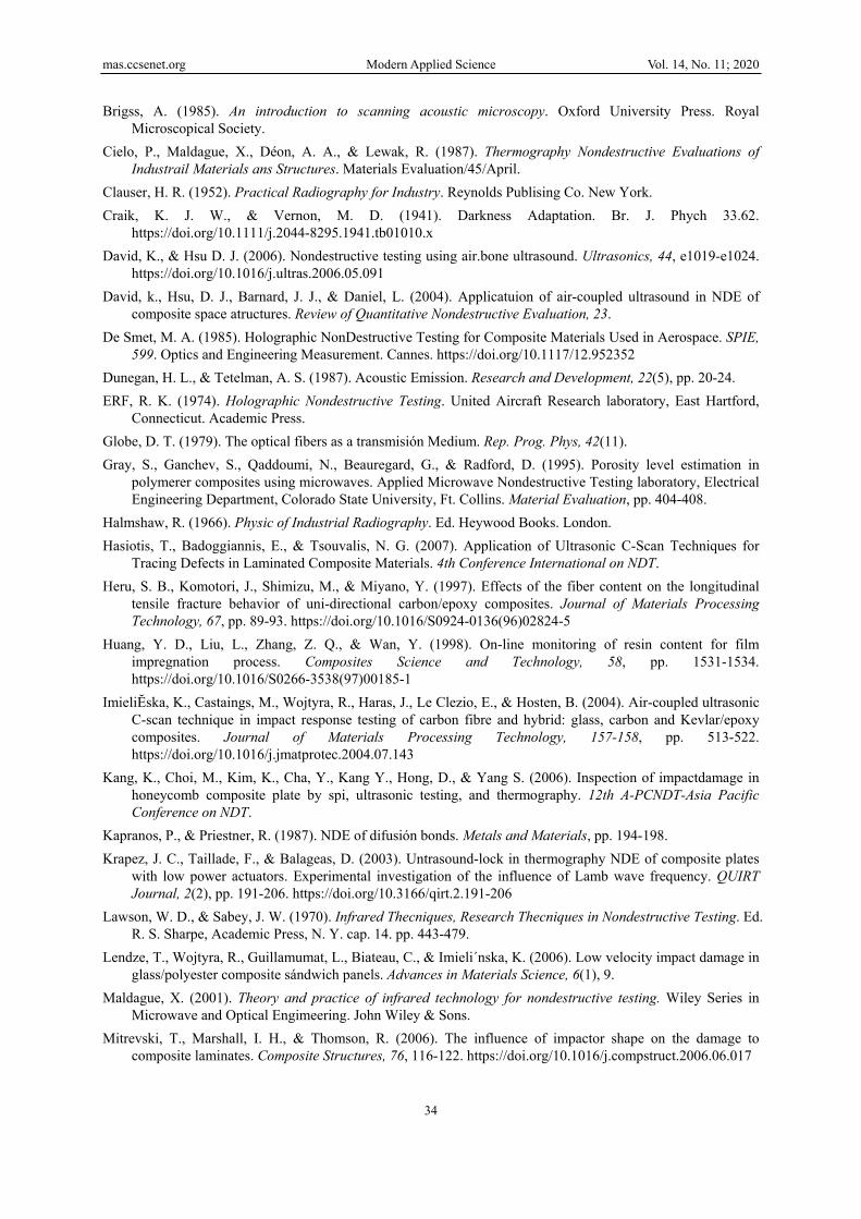
mography corras a narrow ve
8a and 8b shothe piece in oand the agree
ee the photoghere are gaps
gure 7b, whereateral panel (a
Figure 7a. V
Figresponding to
ertical band of
Figure 7c. Thow radiographne of its curve
ement between
Mod
graph of an ardue to lack ofe discontinuitarrows b).
Visible image o
gure 7b. X-rayo this zone of f light color.
hermographichic images of ed areas. In thn the sandwich
dern Applied Sc
26
rea, located inf resin. The raties can also b
of an area with
y of the area shthe agreemen
c image of thethe sandwich
hem, several dh and the side
cience
n the agreemenadiographic asbe seen in the
h holes due to
hown in figurent is shown in
e area with holh covering, widiscontinuitiese panel.
nt between thspect of the difabrics that f
o lack of resin
e 7a figure 7c, wh
les in figure 7 ith a certain o
s can be observ
Vol. 14, N
he central sandiscontinuity isform the union
here the zone w
overlap area, rved that affec
No. 11; 2020
dwich and s indicated n between
with holes
the whole ct the core,

mas.ccsen
Figure 8dradiograpthe same superficiafigures 8athe two dLikewiseto diffuseclearly viBoth on tareas witmarked wfigure 8f
net.org
Fig
Figure 8c d shows the vphic indication
one. Howeveal and affect a and 8b, is b
discontinuities, in figure 8d,e radiographicisible in the ththe left side oth lack of reswith arrow d (arrow d).
gure 8a
visual aspect on is the one iner, the verticaonly the oute
barely percept. , part of a unic indications mhermographic of figure 8a anin, located inin figure 8b c
Mod
Figureof a fiber breandicated by thal line that apper layer of retible. The ther
on joint practmarked by arrimage in figu
nd on the righn the agreemecoincide exac
dern Applied Sc
27
e 8d ak (arrow a) inhe arrow a in pears in the p
esin, since itsrmographic in
ticed in the nurow c in figur
ure 8f (arrow cht side of figuent between thctly with those
cience
n the inner fafigure 8b, bei
photograph in radiographic
nspection of th
ucleus (arrow res 8a and 8bc). ure 8b, there ahe sandwich ae seen in the
Figure 8b
Fbric of the pieing presented figure 8e (ar
c indication, mhe area did no
c) can also be. The indicatio
are dark areas and the side pthermographi
Vol. 14, N
Figure 8e ece. The corr in figure 8c rrow b), shoulmarked by arot clearly rev
e seen, which ons due to th
caused by capanels. The inic image repr
No. 11; 2020
esponding a detail of ld be very rrows b in eal any of
gives rise e joint are
avities and ndications esented in

mas.ccsen
Figure 9aaddition twhere thecorresponalthough
net.org
Figure 8f. a represents thto a slightly cey cannot be nds to the thethe X-ray pro
Figure 9b. seal (arrow (arrow c) o
Thermographhe radiographcurved verticaobserved by
ermography oovides more in
Figure 9a. X
. Photo showinw b) and a breof the core
Mod
hy correspondic image of an
al indication. Tvisual inspecf this area, sh
nformation in
X-ray showing
ng a eak
dern Applied Sc
28
ding to the saman area where These discont
ction, since thhows very remthis case (Hal
tissue rupture
Figu
cience
me area as the folds and brotinuities must
he piece is pamarkable conlmshaw, 1966
es and other d
ure 9c. Visual
radiography ioken tissue aret be on the ouinted on that cordance betw).
iscontinuities
aspect of a co
Vol. 14, N
in figure 8b e detected (ar
uter side of thside. Figure
ween the two
ore break
No. 11; 2020
rrow a), in he radome, 9d, which
o methods,

mas.ccsen
The arrowwith the nthe indica
Core breawith the aother hanin the plaseen in ficore comthat of thradiograpThe irregof the tiss
net.org
ws b in the ennaked eye whations provide
aks, such as tarrow c in figund, these discoace indicated bigure 9c. The
mpared to the mhe breaks, sincphic detection gularities in thsue (figure 9a
Figure 9ntire group of hen the surfaceed by the radio
Figure 9ethe one shownure 9b does noontinuities proby the arrow dradiographic material that cce other mate( Lendze et ae distribution , arrow f) are
Mod
9d. Thermogrfigures 9 poine from which ographic and t
e. Thermograpn in Figure 9ot give an indi
ovide a very cld in figure 9e,undetectabilitcomposes the erials, such asl., 2006; Kangof resin showclearly observ
dern Applied Sc
29
raphy of the arnt to a joint init is viewed isthermographic
phy showing a9c, are not detication in the lear indication, where a branty of the foam"skins". The
s fillers and ag et al., 2006)
wn in figure 9aved in radiogr
cience
rea shown in f the foam cors not painted, c methods, res
a branched cotectable radioradiographic p
n when inspecnched break a
m core breaks case of the jo
adhesives, may. a by arrows e raphy, but not
figure 9a e. Figure 9b swhile figures
spectively.
re ruptura graphically. Tpicture of figucted by thermoppears, whichis due to the l
oints in the coy exist in the
and the deformin thermograp
Vol. 14, N
shows what it s 9a and 9d, 9e
Thus, the breaure 9a (arrow ography, as cah is not the salow density ofore is not com joint, which
rmations in thephy.
No. 11; 2020
looks like e compare
ak marked c). On the an be seen me as that f the foam
mparable to facilitates
e structure

mas.ccsen
The photodeep dentof thickneX-ray) ofprobably
The groupgiving rislayers of As it canappearancfigure, it that in thaWhen theimages, athere are
net.org
F
ograph in figuts and tracks, ess that they rf the prints, shdue to the fac
Figurep of figures 1se to a "throufabric are bro
n be seen in fce of this in rcan be deduc
at area the nuce fabric has aas shown in thdeformations
Figure 10a. Phof the outer faure 10a corresinclined at 45
represent. Thehows us an indct that the fabr
e 10c. Thermo1 illustrates a gh crack". In
oken on the infigure 11b, thradiography iced that the twcleus is also ba shortage of he area indicatof the tissue o
Mod
hotograph of aace of a radomsponds to an a5 degrees. Thee thermographdication of darric contains ad
ographic imageset of almost the photograpner side, its ra
he outer side is indicated bywo ruptures abroken, the set
resin, its struted by the arror deviations i
dern Applied Sc
30
an area me area of the exte X-ray in figuhy (figure 10c)rk color that idditional resin
e correspondit coincidental ph of figure 1adiographic inof the piece y the arrow b
are very close t of the three ducture (weft arow c in figurein its direction
cience
Figu show
ternal face of ure 10b clearly), besides provs associated w
n in that area.
ing to the areabreaks in the
11a you can sndication is malso shows a
b in figure 11but their proj
discontinuitiesand warp) is pe 11c. Likewin (arrow d in f
ure 10b. X-raywn in figure 1a radome in wy shows the foviding indicat
with the dented
a shown in figufabric of bothee a line (arro
marked with tha very severe 1c. From the ejection does ns can be calledperfectly definise, the X-ray figure 11c).
Vol. 14, N
y of the area 10a which you canfootprints due tions (not as cd area; this ind
ure 10a h "skins" and iow a) in whic
he arrow a in ftear of the faexamination onot coincide ad "through craned in the radis also able to
No. 11; 2020
n see quite to the loss lear as the dication is
in the core ch the two figure 11c. abric. The of the last and, given ack". diographic o reveal if

mas.ccsen
FIn the phthe one mmarked wwhat it senot due tdeficit exoriginate Likewiseis origina
net.org
Figur tear i
Figure 11c. X-hotograph showmarked with awith arrows b eems, and is cto breaks, but xtends around
during the l, it is possible
ated when the
re 11a. Photogn the fabric on
-ray showing wn in figure arrow a is a bare not detectcorroborated brather are cathe linear vis
life in servicee that in the plpiece is subm
Mod
graph showingn the inside
the breaks in 12, three discbreak in the fed by any metby radiographused by the eual indicatione, delaminatiolace where the
mitted to effort
dern Applied Sc
31
g a
figures 11a ancontinuities cafabric that givthod, except v
hic examinatioexistence of an in a much laons in the "se linear indicats.
cience
Figure showin
nd 11b, togethan be seen, indves a clear invisual, as longons of the areareas with a sharger area thanskins" or det
ation is found,
11b. Image ofng a very seve
her with other dicated by arr
ndication in Xg as the surfaca, is that theshortage of resn the same, anachments in a breakage of
Vol. 14, N
f the exterior ere break
discontinuitierows a and b.
X-ray, but the ce is not paintese visual indicsin. The area nd may alreadthe union "sf the fibers of
No. 11; 2020
face
es . Of these, two lines
ed. In fact, cations are with resin
dy exist, or skin"-core. f the fabric

mas.ccsen
4. ConcluTwo kindthe tests determineis sufficinon-destr4.1 RecomRegardinthe purpounderlinesufficientsince thisCertainlyabsence discontinmagnitudof the objThe otherabout howhighlighteAs regardthe coverglobal judBearing iessential will be suvisual insdetachmeinspectionand radiobreaks insonic techseem, rem
net.org
Fi
usion ds of conclusithemselves ine whether the ient. The latructive tests prmmendations
ng the determinose of this pape the improprt criteria to des is not the c
y the absence of discontinu
nuities, identifide and amountject. That is: ir conclusionsw the "concued by them, bds the performrage of the kdgement on thin mind the exminimum theufficient, for spection madeents. And onlyn, the radiogrographic inspn the core are hnique will bemains to be co
igure 12. Visib
ons are drawnn relation to tobject is suita
tter is intendrovides to the
nation of its uper to explain riety of underetermine whacase, the mulof indication
uities. But thfiable at least mt. In the absenits good behav, which are th
urrent" methodut also, and m
mance of the mknowledge reghe quality of thxperience obtae tests to be asimilar piece
e before paintiy at specific praphy. If the pection being to be detecte
e necessary toonfirmed by te
Mod
ble image of a
n from the resthe purpose oable for the puded to show knowledge o
usefulness, wewhether the r
rtaking tests wt is to be soultiplication of
ns, if given, "his is not themorphologicance of specificvior in servicehose that justds not only re
mainly, how thmethods as "cogarding the exhe object, whiained and in aapplied in the s that are noting them, and
points to confipart is painted
necessary whd in a part th
o reveal flat diechnology.
dern Applied Sc
32
an area in the
sults of the tesof the inspecturpose for wh
w the degree of the discontin
e will limit ourradome is usewithout the p
ught and whatf tests could "could" be inte case, and tally, that cannocations the on
e according to tify this workeinforce confihey help each omplementaryxistence of dich engineerin
accordance witinspection of
t painted on ad the sonic inspirm or elucida
d on one or bohen the part
hat is painted oiscontinuities.
cience
outer curved p
sts carried oution, which in
hich it was conof coverage
nuities affectin
rselves to a coful or should
project enginet technologicalead to more
terpreted in athere are indot be given "a
nly sensible ththe purpose o
k, can be summidence in the other to estaby", it seems cliscontinuities,ng should valuth the principlf an object, it any of their fapection (Lamb
ate the existenoth sides, morhas one painon both sides But this conj
part of a radom
t. The first refn this or any onceived; that ie that the cng the object.
ouple of considbe rejected. F
eering having al meaning is e confusion th
good sense ications that
a priori" as irrehing to do is toof use with whmarized in threal existencelish their natulear that it rep, and a valuaue. le of good praseems plausi
aces, with theb waves) to de
nce of discontire methods muted side, and . In all cases ecture, howev
Vol. 14, N
me
fers to the useother case is is, whether its
concurrence o
derations, sinFirstly, it is ne
previously eto be found.
than useful knas an indicatican be inter
elevant becauo quarantine thich it was mahe evidence she of the disco
ure and morphpresents an exable contribut
actice of reducible that in the direct and tr
detect delamininuities foundust be used, w
d even thermothe inspection
ver well found
No. 11; 2020
efulness of simply to
s "quality" of several
ce it is not ecessary to established Secondly, nowledge. ion of the rpreted as
use of their the quality ade. hown in it ontinuities
hology. xtension of ion to the
cing to the he future it ranslucent ations and
d by visual with visual ography if n with the ded it may

mas.ccsenet.org Modern Applied Science Vol. 14, No. 11; 2020
33
4.2 Limitations In the case of visual inspection, the method provides immediate indications that often do not require elaborate interpretation. However, one should not be tempted to believe that 'what you see' is 'how you look'. In many cases, what is seen must be elaborated according to the materialographic aspects of the problem and even of the observation technique itself, such as the color of the light used, whether or not it is polarized, incidence of illumination, etc. Radiographic inspection of this type of material does not present any difficulty. These materials are not very absorbent and require lower energies for inspection. If the thickness to be examined is small, the problem may be its excessive transparency that will force to have X-ray tubes with very low inherent filtration and even to dispense with the film cover, which will force to work under safety light. However, although it does not pose serious radiographic problems, the defectology of the composite material is usually not very conducive to radiographic inspection, since it consists of laminar-type discontinuities (delaminations) arranged parallel to the image and whose radiographic detectability is extremely poor. Another issue is the cracks or pores that could be present in the inspected piece, which do not present a problem to be evidenced, however this type of discontinuities are less frequent than the delaminations. Manual testing by ultrasound requires highly qualified personnel. The large number of critical decisions to be made, together with the poor documentation of results, reduces the reliability of the tests, pushing this problem to the development of automated procedures. Small, irregular, rough or thin material samples are difficult to inspect. Heterogeneities very close to the surface are difficult to detect. Calibration of the test system and determination of certain characteristics of the defects to be inspected requires the use of standard or reference samples. Defect detection techniques using Lamb waves (sonic techniques) allow continuous monitoring of the state of the structure and allow the integration of detection systems in critical areas of the part that require constant maintenance. These waves are dispersive, varying their speed of propagation according to the frequency. The efficiency of the transducer can be affected when the elements that compose it are close to the edge of the plate, and the latter can act in a reactive manner by interfering with the frequency band of the nodes. For the study of the edges, finite element analysis techniques are proposed. The inspection using ultraviolet light does not detect too deep defects, and requires an electric power source. The roughness of the surface under study can affect the sensitivity of the test. The methods of infrared thermography pulsed by reflection (infrared camera in front of the part as well as the heat source) and by transmission (infrared camera behind the part) present good results for small thicknesses, however, it is necessary a good adjustment on a test specimen with defects of different sizes and at different depths to adjust well this technique. It is very important the adjustments of the heat power provided by the focus and the times of incidence of the heat in the part since the processes of heat transfer could result negative in the visualization of the possible defects in the part. Acknowledgements The authors wish to thank the Instituto Nacional de Técnica Aeroespacial (INTA), especially the Central Remote Sensing and Non-Destructive Testing Laboratories. References ASM International Handbook Committee. (1989). Engineered Materials Handbook, vol. 1 Composites. Baker, A. A., Jones, R., & Callinan, R. J. (1985). Damage tolerance od graphite/epoxy composites. Composite
Structures, 4, 15-44. https://doi.org/10.1016/0263-8223(85)90018-2 Balageas, D. (2005). Métodos innovadores de inspección de estructuras de materiales compuestos. Materiales
Compuestos, 5, ed. V Amigó et al., Editorial de la Universidad Politécnica de Valencia, pp. 1065-1080. Bales, M. J., & Bishop, C. C. (1994). Pulsed Infrared Imaging: a New NDT Methodology of Aboveground
Storage Tnaks. Bales Scientific, Inc., 1620. Tice Valley Blvd., Walnut Creek, CA 94595. Materials Evaluation.
Barbero, E. J. (1999). Introduce to Composite Materials Design. Taylord & Francis, Inc. Bermúdez de Castro, J. (1963). Los rayos X y sus aplicaciones industriales. Ed. Montecorvo. Madrid. Bishop, S. M. (1985). The mechanical performance and impact behavior of carbon fibre reinforced PEEK.
Composite Structures, 3, pp. 295-318. https://doi.org/10.1016/0263-8223(85)90059-5
mas.ccsenet.org Modern Applied Science Vol. 14, No. 11; 2020
34
Brigss, A. (1985). An introduction to scanning acoustic microscopy. Oxford University Press. Royal Microscopical Society.
Cielo, P., Maldague, X., Déon, A. A., & Lewak, R. (1987). Thermography Nondestructive Evaluations of Industrail Materials ans Structures. Materials Evaluation/45/April.
Clauser, H. R. (1952). Practical Radiography for Industry. Reynolds Publising Co. New York. Craik, K. J. W., & Vernon, M. D. (1941). Darkness Adaptation. Br. J. Phych 33.62.
https://doi.org/10.1111/j.2044-8295.1941.tb01010.x David, K., & Hsu D. J. (2006). Nondestructive testing using air.bone ultrasound. Ultrasonics, 44, e1019-e1024.
https://doi.org/10.1016/j.ultras.2006.05.091 David, k., Hsu, D. J., Barnard, J. J., & Daniel, L. (2004). Applicatuion of air-coupled ultrasound in NDE of
composite space atructures. Review of Quantitative Nondestructive Evaluation, 23. De Smet, M. A. (1985). Holographic NonDestructive Testing for Composite Materials Used in Aerospace. SPIE,
599. Optics and Engineering Measurement. Cannes. https://doi.org/10.1117/12.952352 Dunegan, H. L., & Tetelman, A. S. (1987). Acoustic Emission. Research and Development, 22(5), pp. 20-24. ERF, R. K. (1974). Holographic Nondestructive Testing. United Aircraft Research laboratory, East Hartford,
Connecticut. Academic Press. Globe, D. T. (1979). The optical fibers as a transmisión Medium. Rep. Prog. Phys, 42(11). Gray, S., Ganchev, S., Qaddoumi, N., Beauregard, G., & Radford, D. (1995). Porosity level estimation in
polymerer composites using microwaves. Applied Microwave Nondestructive Testing laboratory, Electrical Engineering Department, Colorado State University, Ft. Collins. Material Evaluation, pp. 404-408.
Halmshaw, R. (1966). Physic of Industrial Radiography. Ed. Heywood Books. London. Hasiotis, T., Badoggiannis, E., & Tsouvalis, N. G. (2007). Application of Ultrasonic C-Scan Techniques for
Tracing Defects in Laminated Composite Materials. 4th Conference International on NDT. Heru, S. B., Komotori, J., Shimizu, M., & Miyano, Y. (1997). Effects of the fiber content on the longitudinal
tensile fracture behavior of uni-directional carbon/epoxy composites. Journal of Materials Processing Technology, 67, pp. 89-93. https://doi.org/10.1016/S0924-0136(96)02824-5
Huang, Y. D., Liu, L., Zhang, Z. Q., & Wan, Y. (1998). On-line monitoring of resin content for film impregnation process. Composites Science and Technology, 58, pp. 1531-1534. https://doi.org/10.1016/S0266-3538(97)00185-1
ImieliĔska, K., Castaings, M., Wojtyra, R., Haras, J., Le Clezio, E., & Hosten, B. (2004). Air-coupled ultrasonic C-scan technique in impact response testing of carbon fibre and hybrid: glass, carbon and Kevlar/epoxy composites. Journal of Materials Processing Technology, 157-158, pp. 513-522. https://doi.org/10.1016/j.jmatprotec.2004.07.143
Kang, K., Choi, M., Kim, K., Cha, Y., Kang Y., Hong, D., & Yang S. (2006). Inspection of impactdamage in honeycomb composite plate by spi, ultrasonic testing, and thermography. 12th A-PCNDT-Asia Pacific Conference on NDT.
Kapranos, P., & Priestner, R. (1987). NDE of difusión bonds. Metals and Materials, pp. 194-198. Krapez, J. C., Taillade, F., & Balageas, D. (2003). Untrasound-lock in thermography NDE of composite plates
with low power actuators. Experimental investigation of the influence of Lamb wave frequency. QUIRT Journal, 2(2), pp. 191-206. https://doi.org/10.3166/qirt.2.191-206
Lawson, W. D., & Sabey, J. W. (1970). Infrared Thecniques, Research Thecniques in Nondestructive Testing. Ed. R. S. Sharpe, Academic Press, N. Y. cap. 14. pp. 443-479.
Lendze, T., Wojtyra, R., Guillamumat, L., Biateau, C., & Imieli´nska, K. (2006). Low velocity impact damage in glass/polyester composite sándwich panels. Advances in Materials Science, 6(1), 9.
Maldague, X. (2001). Theory and practice of infrared technology for nondestructive testing. Wiley Series in Microwave and Optical Engimeering. John Wiley & Sons.
Mitrevski, T., Marshall, I. H., & Thomson, R. (2006). The influence of impactor shape on the damage to composite laminates. Composite Structures, 76, 116-122. https://doi.org/10.1016/j.compstruct.2006.06.017

mas.ccsenet.org Modern Applied Science Vol. 14, No. 11; 2020
35
Miyano, Y., McMurray, M. K., Kitade, N., Nakada, M., & Mohri, M. (1994). Role of matrix resino n the flexure static behavior of unidirectional pitch-based carbon fiber laminates. Advanced Composite Materials, 4(2), pp. 87-99. https://doi.org/10.1163/156855194X00222
Mouritz, A. P., Townsend, C., & Shah Khan, M. Z. (2000). Nondestructive detection of fatigue damage in thick composites by pulse-echo ultrasonics. Composites Science and Technology, 60, pp. 23-32. https://doi.org/10.1016/S0266-3538(99)00094-9
Ochelski, S. (2004). Experimental methods in construction composites mechanics. WNT, Warszawa (in Polish). Padmanabhan, K., & Kishore E. (1995). Failure behaviour of carbon fibre/epoxy composites in pìn-ended
buckling and vending test. Composites, 26(3), pp. 201-206. https://doi.org/10.1016/0010-4361(95)91383-G Pollock, A. A. (1998). Acoustic Emission Inspection. Metal Handbook. Vol. 17. Nondestructive and Quality
Control, pp. 278-294. Potel, C., Chotard, T., Belleval, J. F., & Benzeggagh, M. (1998). Characterization of composite material by
ultrasonic methods. Composites Part B, pp. 159-169. https://doi.org/10.1016/S1359-8368(97)00006-1 Rámirez López, Fc., Del Ojo, G., Fernández Soler, M. A., Valdecantos, C., Alonso, A., & De los Ríos, J. M.
(1996). Métodos de Ensayos No Destructivos, Instituto de Técnica Aeroespacial (INTA). Ramírez, F., Delojo, G., Fernández, M. A., Valdecantos, C., Alonso, A., & De los Ríos, J. M. (1996). Métodos
de Ensayos No Destructivos. Instituto Nacional de Técnica Aeroespacial “Esteban Terradas”. Tomos I y II. Madrid. España.
Reynolds, V. N. (1996). Optical and Infrared Methods, (part. 8 of Capabilities and Limitations of NDT). Ed. P. D. Hanstead). The Br. Inst. of NDT. Northampton.
Rosenthal, D. M., & Trolinger, J. D. (1995). Holographic Nondestructive Testing. Metro-Laser, 18006 Skypark Circle. Suite 108, Irvine. Materials Evaluation.
Sanglier, G., López, E. J., Cesteros, S., & González, R. A. (2020). The Search for ‘Defects’ by Non-invasive Techniques: Developmente and Application of Pulsed-Transmissive and Refective Thermography in Fiberglass Material. Contemporary Engineering Sciences. https://doi.org/10.12988/ces2020.91245
Sanglier, G., Del Ojo, G., De Miguel, J., & Peñaranda, J. A. (2003). Estudio mediante Ensayos No Destructivos dela cubierta (“Radomo”) de un sistema experimental de radar de apertura sintética. 10º Congreso nacional de E.N.D. Asociación Española de Ensayos No Destructivos. Cartagena, España.
Scarponi, C., & Briotti, G. (2000). Ultrasonic technique for the evaluation of delamination on CFRP, GFRP, KFRP composite materials. Composites: Part B, 31, pp. 237-243. https://doi.org/10.1016/S1359-8368(99)00076-1
Silk, M. G. (1982). Defect detection and sizing in metals using ultrasound. International Metal Rev., 1, pp. 28-50. https://doi.org/10.1179/imr.1982.27.1.28
Spanner J. C. (1974). Acoustic Emission Techniques and Aplication. ASNT. Columbus (Ohio) 43221. Sproull, W. T. (1946). X Rays in Practice. Ed. Mc Graw Hill. New York.
https://doi.org/10.1097/00010694-194608000-00018 Stetson, K. A., & Ferraro, P. (1993). Cooperative Research and Development Programo on Holographic
Nondestructive Testing. Task II Report. Von Helmholtz, H. (1963). Handbook of Physiological Optics. Reimpresión por Stanthall. Dover. Wan, H., Ning, F., Hu, Y., Fernando, PKSC, & Pei, Z. J. (2016). Surface grinding of carbon fiber-reinforced
plastic composites using rotatory ultrasonic machining: Effects of tool variables. Advanced in Mechanical Engineering, 8(9), 1-14. https://doi.org/10.1177/1687814016670284
Copyrights Copyright for this article is retained by the author(s), with first publication rights granted to the journal. This is an open-access article distributed under the terms and conditions of the Creative Commons Attribution license (http://creativecommons.org/licenses/by/4.0/).