Embed Size (px)
Citation preview
The SKF MultiFlex multi-line pump is a pos-
itive-displacement pump with multiple uti-
lizable outlets. The displacement is continu-
ously variable.
Special characteristics
The SKF MultiFlex multi-line pump is con-
structed as a radial piston pump in a modu-
lar design. Up to five pump elements, each
with one, two, or four outlets, can be “com-
bined” so that the number of outlets can be
adapted to current requirements in the best
possible way.
This simple stacking design also allows for
subsequent expansion or reduction of the
number of pump outlets.
The displacement of a pump element's
outlets is continuously variable (stepless ad-
justment) from outside.
Continuous variability and an extended
speed range result in an extremely broad
spectrum of delivery rates. This makes the
pump highly attractive as a feed pump in
circulating lubrication systems with low cir-
culation rates (up to 30 cm3/min per outlet)
or as a multi-circuit pump to supply multiple
independent lubrication zones.
The pump can be driven in either direction
of rotation as desired.
Its operating pressure is max. 63 bar, with
up to 100 bar for short periods.
The design of the RA/RAB multi-line pump
permits it to pump both mineral-based and
synthetic-based oils and greases.
RA 1UA .... RA 1M .... RAB 07 ....
Multi-line pumps
Product series RAFor oil and greaseFor use in SKF MultiFlex multi-line lubrication systems
PU
B L
S/P
2 1
11
03
EN
· 1
-30
00
-EN
Contents
Special characteristics . . . . . . . . . . . . . . . . . . . . . . . . . . . . . . . 1
Mode of operation . . . . . . . . . . . . . . . . . . . . . . . . . . . . . . . . . . 3
Design . . . . . . . . . . . . . . . . . . . . . . . . . . . . . . . . . . . . . . . . . . . . 3
Displacement . . . . . . . . . . . . . . . . . . . . . . . . . . . . . . . . . . . . . . 4
MultiFlex designs
Rotary drive, coaxial . . . . . . . . . . . . . . . . . . . . . . . . . . . . . . . 5
Rotary drive with coaxial gear . . . . . . . . . . . . . . . . . . . . . . . . 6
Rotary drive with bevel gear . . . . . . . . . . . . . . . . . . . . . . . . . 7
Electric motor drive, coaxial . . . . . . . . . . . . . . . . . . . . . . . . . 8
Electric motor drive with coaxial gear . . . . . . . . . . . . . . . . . 9
Electric motor drive with bevel gear . . . . . . . . . . . . . . . . . . 10
Rotary drive with bevel gear and reservoir . . . . . . . . . . . . 11
Electric motor drive with
coaxial gear and reservoir . . . . . . . . . . . . . . . . . . . . . . . . . 12
Electric motor drive with
bevel gear and reservoir . . . . . . . . . . . . . . . . . . . . . . . . . . . 14
Electric motor drive with
3, 7, or 15 liter reservoir . . . . . . . . . . . . . . . . . . . . . . . . . . 16
Fill level switch . . . . . . . . . . . . . . . . . . . . . . . . . . . . . . . . . . . . .18
Accessories . . . . . . . . . . . . . . . . . . . . . . . . . . . . . . . . . . . . . . . .19
Spare parts . . . . . . . . . . . . . . . . . . . . . . . . . . . . . . . . . . . . . . . .20
2
PU
B L
S/P
2 1
11
03
EN
· 1
-30
00
-EN
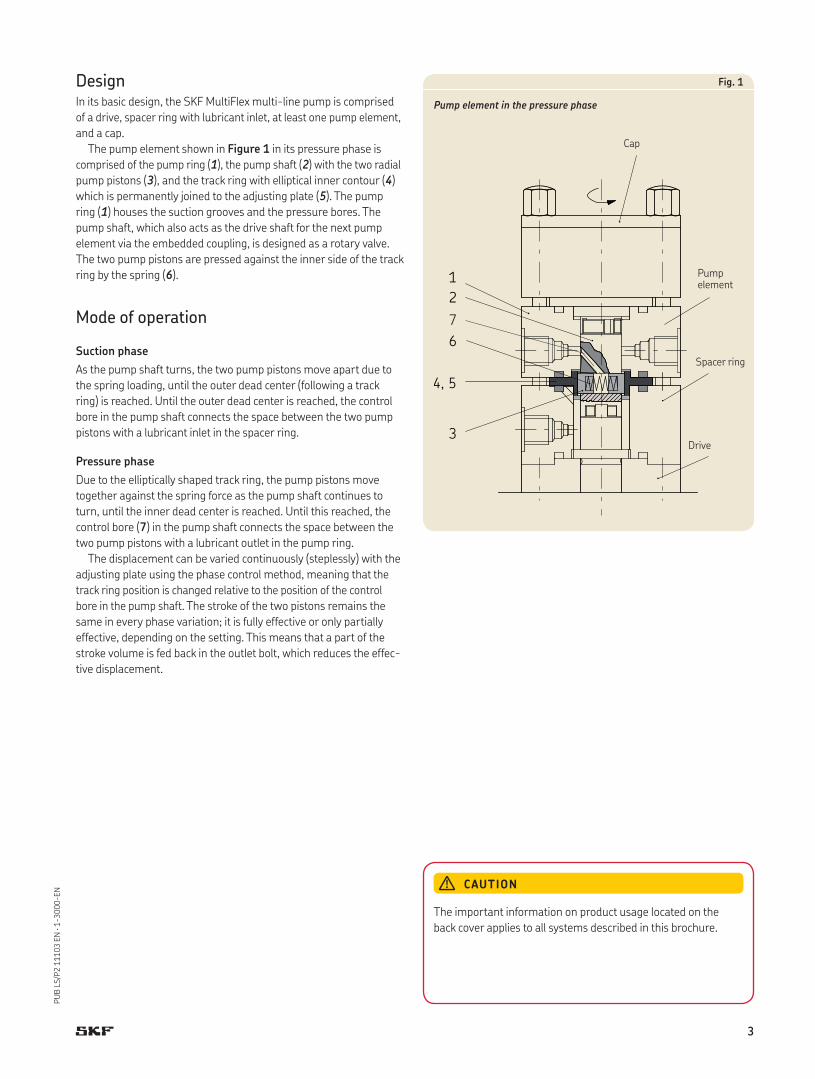
Design In its basic design, the SKF MultiFlex multi-line pump is comprised
of a drive, spacer ring with lubricant inlet, at least one pump element,
and a cap.
The pump element shown in Figure 1 in its pressure phase is
comprised of the pump ring (1), the pump shaft (2) with the two radial
pump pistons (3), and the track ring with elliptical inner contour (4)
which is permanently joined to the adjusting plate (5). The pump
ring (1) houses the suction grooves and the pressure bores. The
pump shaft, which also acts as the drive shaft for the next pump
element via the embedded coupling, is designed as a rotary valve.
The two pump pistons are pressed against the inner side of the track
ring by the spring (6).
Mode of operation
Suction phase
As the pump shaft turns, the two pump pistons move apart due to
the spring loading, until the outer dead center (following a track
ring) is reached. Until the outer dead center is reached, the control
bore in the pump shaft connects the space between the two pump
pistons with a lubricant inlet in the spacer ring.
Pressure phase
Due to the elliptically shaped track ring, the pump pistons move
together against the spring force as the pump shaft continues to
turn, until the inner dead center is reached. Until this reached, the
control bore (7) in the pump shaft connects the space between the
two pump pistons with a lubricant outlet in the pump ring.
The displacement can be varied continuously (steplessly) with the
adjusting plate using the phase control method, meaning that the
track ring position is changed relative to the position of the control
bore in the pump shaft. The stroke of the two pistons remains the
same in every phase variation; it is fully effective or only partially
effective, depending on the setting. This means that a part of the
stroke volume is fed back in the outlet bolt, which reduces the effec-
tive displacement.
3
4, 5
2
6
1
7
Fig. 1
Pump element in the pressure phase
Cap
Spacer ring
Drive
CAUTION
The important information on product usage located on the
back cover applies to all systems described in this brochure.
Pump element
3
PU
B L
S/P
2 1
11
03
EN
· 1
-30
00
-EN
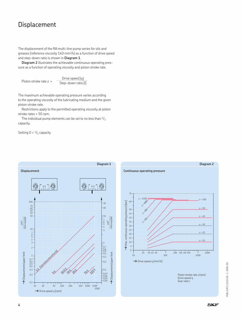
The displacement of the RA multi-line pump series for oils and
greases (reference viscosity 140 mm2/s) as a function of drive speed
and step-down ratio is shown in Diagram 1.
Diagram 2 illustrates the achievable continuous operating pres-
sure as a function of operating viscosity and piston stroke rate.
Piston stroke rate z =
Drive speed [Step-down ratio [l]
The maximum achievable operating pressure varies according
to the operating viscosity of the lubricating medium and the given
piston stroke rate.
Restrictions apply to the permitted operating viscosity at piston
stroke rates > 50 rpm.
The individual pump elements can be set to no less than 1/3
capacity.
Setting 0 = 1/3 capacity
Displacement
Diagram 1
Displacement
10 20 50 100 200 500 1000 1500 2000
100
70605040
30
10
7654
3
2
1
0,70,60,50,4
0,3
0,2
0,1
30
20
10
7654
3
1
0,70,60,50,4
0,3
0,2
0,1
0,070,060,050,04
1:1
(Getrie
beun
tersetzu
ng)
5:1
15:1
10,5
:1
25:1
75:1
125:
1
cm3
min
+ou
tlet
cm3
min
+ou
tlet
†Di
spla
cem
ent/
upper
lim
it
†Drive speed [rpm]
†Di
spla
cem
ent/
upper
lim
it
Diagram 2
Continuous operating pressure
Piston stroke rate z (rpm)Drive speed Gear ratio l
† Drive speed [mm2/s]
†Ma
x. c
onti
nu
ous
oper
atin
g pre
ssu
re [b
ar]
4
PU
B L
S/P
2 1
11
03
EN
· 1
-30
00
-EN
Rotary drive, coaxial
Technical data
GeneralMounting position . . . . . . . . . . . . . . . . . . . . . . AnyAmbient temperature . . . . . . . . . . . . . . . . . . . –15 to +80°C
PumpType . . . . . . . . . . . . . . . . . . . . . . . . . . . . . . . . . Radial piston pumpOperating pressure . . . . . . . . . . . . . . . . . . . . . 63 bar1)
Short-term pressure . . . . . . . . . . . . . . . . . . . . 100 barNumber of combinable pump elements . . . . . . . . . . . . . . . . . . . . . . . . Max. 5Outlets per pump element . . . . . . . . . . . . . . . . 1, 2 or 4Displacement variability per pump element . . . . . . . . . . . . . . . . . . . . . . . . . Continuously variableDisplacement per outlet and revolution of the pump shaft . . . . . . . . . . . . . . Max. 0.02 cm3
Drive speed . . . . . . . . . . . . . . . . . . . . . . . . . . . 10 to 1500 rpmDirection of rotation . . . . . . . . . . . . . . . . . . . . . Clockwise or
counterclockwise2)
Lubricant . . . . . . . . . . . . . . . . . . . . . . . . . . . . . Mineral oils3)
Temperature range . . . . . . . . . . . . . . . . . . . . . –15 to +80°COperating viscosity . . . . . . . . . . . . . . . . . . . . . . 25 to 2500 mm2/sSuction height . . . . . . . . . . . . . . . . . . . . . . . . . 500 mmIntake tube inside diameter . . . . . . . . . . . . . . . 4 mm
Weight with pump element 1 . . . . . . . . . . 2.74 kg 2 . . . . . . . . . . 1.59 kg 3 . . . . . . . . . . 1.97 kg 4 . . . . . . . . . . 2.36 kg 5 . . . . . . . . . . 2.74 kg
1) Max. operating pressure – see page 4, diagram 2.2) Standard: clockwise.3) For synthetic lubricants on request.
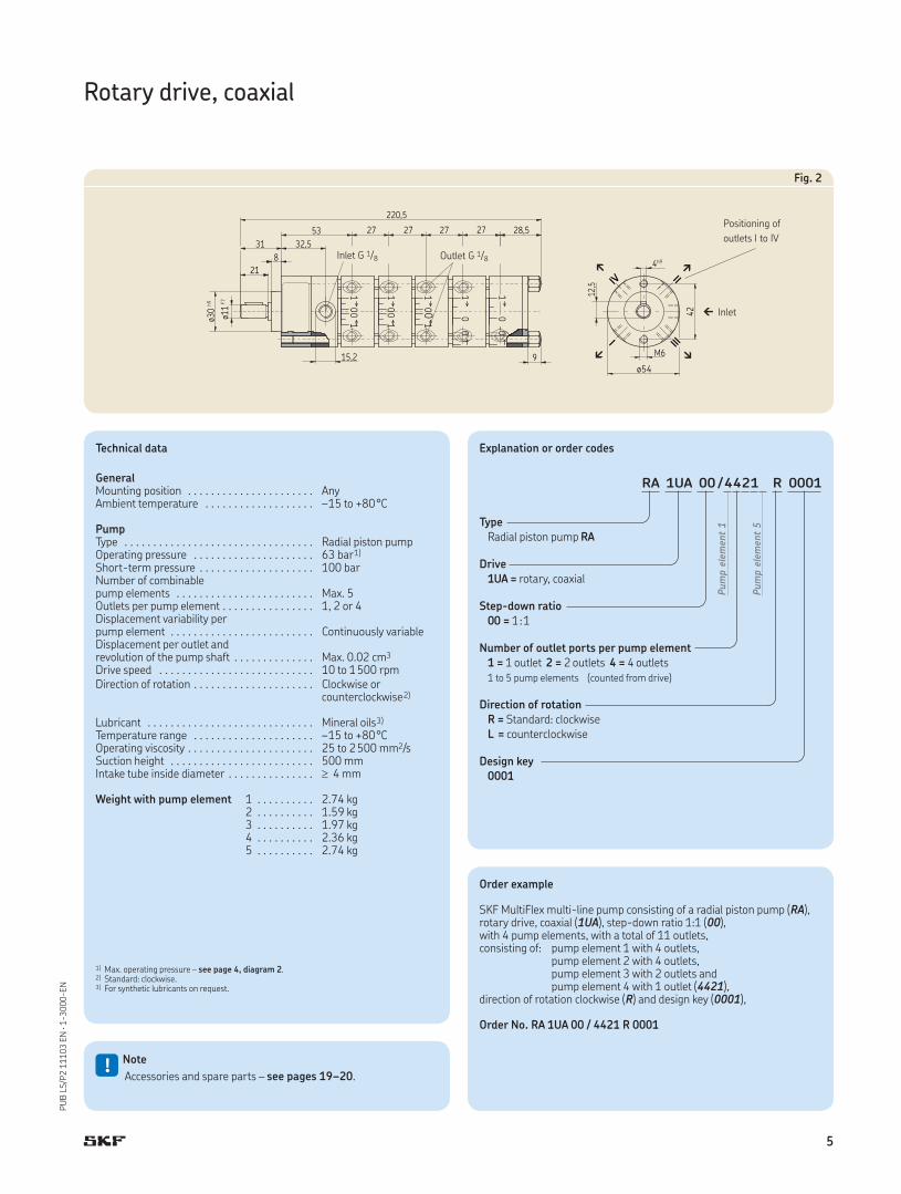
Fig. 2
Inlet G 1/8 Outlet G 1/8
Positioning of
outlets I to IV
Inlet
Order example
SKF MultiFlex multi-line pump consisting of a radial piston pump (RA), rotary drive, coaxial (1UA), step-down ratio 1:1 (00), with 4 pump elements, with a total of 11 outlets, consisting of: pump element 1 with 4 outlets, pump element 2 with 4 outlets, pump element 3 with 2 outlets and pump element 4 with 1 outlet (4421), direction of rotation clockwise (R) and design key (0001),
Order No. RA 1UA 00 / 4421 R 0001
!Note
Accessories and spare parts – see pages 19–20.
Explanation or order codes
RA 1UA 00 / 4421 R 0001
Type
Radial piston pump RA
Drive
1UA = rotary, coaxial
Step-down ratio
00 = 1:1
Number of outlet ports per pump element
1 = 1 outlet 2 = 2 outlets 4 = 4 outlets1 to 5 pump elements (counted from drive)
Direction of rotation
R = Standard: clockwiseL = counterclockwise
Design key
0001
Pum
p e
lem
ent
1
Pum
p e
lem
ent
5
5
PU
B L
S/P
2 1
11
03
EN
· 1
-30
00
-EN
Rotary drive with coaxial gear
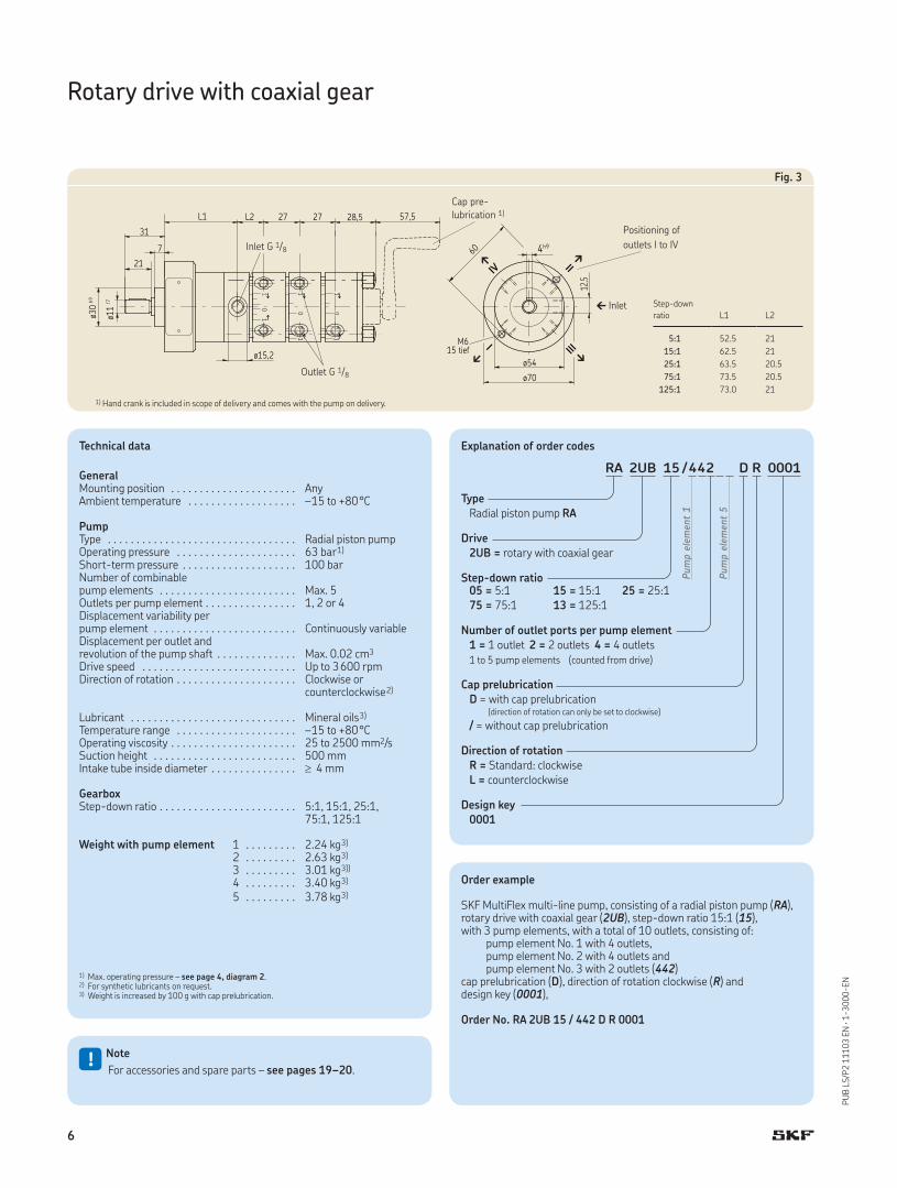
Fig. 3
Technical data
GeneralMounting position . . . . . . . . . . . . . . . . . . . . . . AnyAmbient temperature . . . . . . . . . . . . . . . . . . . –15 to +80°C
PumpType . . . . . . . . . . . . . . . . . . . . . . . . . . . . . . . . . Radial piston pumpOperating pressure . . . . . . . . . . . . . . . . . . . . . 63 bar1)
Short-term pressure . . . . . . . . . . . . . . . . . . . . 100 barNumber of combinable pump elements . . . . . . . . . . . . . . . . . . . . . . . . Max. 5Outlets per pump element . . . . . . . . . . . . . . . . 1, 2 or 4Displacement variability per pump element . . . . . . . . . . . . . . . . . . . . . . . . . Continuously variableDisplacement per outlet and revolution of the pump shaft . . . . . . . . . . . . . . Max. 0.02 cm3
Drive speed . . . . . . . . . . . . . . . . . . . . . . . . . . . Up to 3600 rpmDirection of rotation . . . . . . . . . . . . . . . . . . . . . Clockwise or
counterclockwise2)
Lubricant . . . . . . . . . . . . . . . . . . . . . . . . . . . . . Mineral oils3)
Temperature range . . . . . . . . . . . . . . . . . . . . . –15 to +80°COperating viscosity . . . . . . . . . . . . . . . . . . . . . . 25 to 2500 mm2/sSuction height . . . . . . . . . . . . . . . . . . . . . . . . . 500 mmIntake tube inside diameter . . . . . . . . . . . . . . . 4 mm
GearboxStep-down ratio . . . . . . . . . . . . . . . . . . . . . . . . 5:1, 15:1, 25:1,
75:1, 125:1
Weight with pump element 1 . . . . . . . . . 2.24 kg3)
2 . . . . . . . . . 2.63 kg3)
3 . . . . . . . . . 3.01 kg3))
4 . . . . . . . . . 3.40 kg3)
5 . . . . . . . . . 3.78 kg3)
1) Max. operating pressure – see page 4, diagram 2.2) For synthetic lubricants on request.3) Weight is increased by 100 g with cap prelubrication.
Inlet G 1/8
Outlet G 1/8
Step-down
ratio L1 L2
5:1 52.5 21
15:1 62.5 21
25:1 63.5 20.5
75:1 73.5 20.5
125:1 73.0 21
Inlet
Positioning of
outlets I to IV
Order example
SKF MultiFlex multi-line pump, consisting of a radial piston pump (RA), rotary drive with coaxial gear (2UB), step-down ratio 15:1 (15), with 3 pump elements, with a total of 10 outlets, consisting of: pump element No. 1 with 4 outlets, pump element No. 2 with 4 outlets and pump element No. 3 with 2 outlets (442)cap prelubrication (D), direction of rotation clockwise (R) and design key (0001),
Order No. RA 2UB 15 / 442 D R 0001
!Note
For accessories and spare parts – see pages 19–20.
1) Hand crank is included in scope of delivery and comes with the pump on delivery.
Cap pre-
lubrication 1)
Explanation of order codes
RA 2UB 15 / 442 D R 0001
Type
Radial piston pump RA
Drive
2UB = rotary with coaxial gear
Step-down ratio05 = 5:1 15 = 15:1 25 = 25:175 = 75:1 13 = 125:1
Number of outlet ports per pump element
1 = 1 outlet 2 = 2 outlets 4 = 4 outlets1 to 5 pump elements (counted from drive)
Cap prelubrication
D = with cap prelubrication (direction of rotation can only be set to clockwise)
/ = without cap prelubrication
Direction of rotation
R = Standard: clockwiseL = counterclockwise
Design key
0001
Pum
p e
lem
ent
1
Pum
p e
lem
ent
5
6
PU
B L
S/P
2 1
11
03
EN
· 1
-30
00
-EN
Rotary drive with bevel gear
Technical data
GeneralMounting position . . . . . . . . . . . . . . . . . . . . . . . . . AnyAmbient temperature . . . . . . . . . . . . . . . . . . . . . . –15 to +80°C
PumpType . . . . . . . . . . . . . . . . . . . . . . . . . . . . . . . . . . . . Radial piston pumpOperating pressure . . . . . . . . . . . . . . . . . . . . . . . . 63 bar1)
Short-term pressure . . . . . . . . . . . . . . . . . . . . . . . 100 barNumber of combinable pump elements . . . . . . . . . . . . . . . . . . . . . . . . . . . Max. 5Outlets per pump element . . . . . . . . . . . . . . . . . . . 1, 2 or 4Displacement variability per pump element . . . . . . . . . . . . . . . . . . . . . . . . . . . . Continuously variableDisplacement per outlet and revolution of the pump shaft . . . . . . . . . . . . . . . . . Max. 0.02 cm3
Drive speed . . . . . . . . . . . . . . . . . . . . . . . . . . . . . . 10 to 1800 rpmDirection of rotation . . . . . . . . . . . . . . . . . . . . . . . . Clockwise or
counterclockwise2)
Lubricant . . . . . . . . . . . . . . . . . . . . . . . . . . . . . . . . Mineral oils3)
Temperature range . . . . . . . . . . . . . . . . . . . . . . . . –15 to +80°COperating viscosity . . . . . . . . . . . . . . . . . . . . . . . . . 25 to 2500 mm2/sSuction height . . . . . . . . . . . . . . . . . . . . . . . . . . . . 500 mmIntake tube inside diameter . . . . . . . . . . . . . . . . . . 4 mm
GearboxDrive position . . . . . . . . . . . . . . . . . . . . . . . . . . . . . A or B
Weight with pump element 1 . . . . . . . . . . . . . 1.69 kg 2 . . . . . . . . . . . . . 2.07 kg 3 . . . . . . . . . . . . . 2.46 kg 4 . . . . . . . . . . . . . 2.84 kg 5 . . . . . . . . . . . . . 3.23 kg1) Max. operating pressure– see page 4, diagram 2.2) Standard: clockwise.3) Synthetic lubricants can be provided on request.
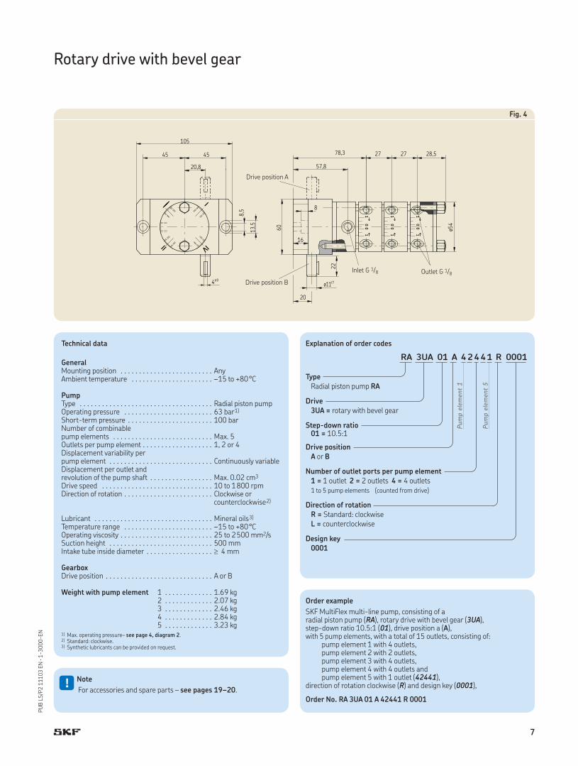
Fig. 4
Drive position A
Inlet G 1/8 Outlet G 1/8
Drive position B
Order example
SKF MultiFlex multi-line pump, consisting of a radial piston pump (RA), rotary drive with bevel gear (3UA), step-down ratio 10.5:1 (01), drive position a (A), with 5 pump elements, with a total of 15 outlets, consisting of: pump element 1 with 4 outlets, pump element 2 with 2 outlets, pump element 3 with 4 outlets, pump element 4 with 4 outlets and pump element 5 with 1 outlet (42441), direction of rotation clockwise (R) and design key (0001),
Order No. RA 3UA 01 A 42441 R 0001
!Note
For accessories and spare parts – see pages 19–20.
Explanation of order codes
RA 3UA 01 A 42441 R 0001
Type
Radial piston pump RA
Drive
3UA = rotary with bevel gear
Step-down ratio01 = 10.5:1
Drive position
A or B
Number of outlet ports per pump element
1 = 1 outlet 2 = 2 outlets 4 = 4 outlets1 to 5 pump elements (counted from drive)
Direction of rotation
R = Standard: clockwiseL = counterclockwise
Design key
0001
Pum
p e
lem
ent
1
Pum
p e
lem
ent
5
7
PU
B L
S/P
2 1
11
03
EN
· 1
-30
00
-EN
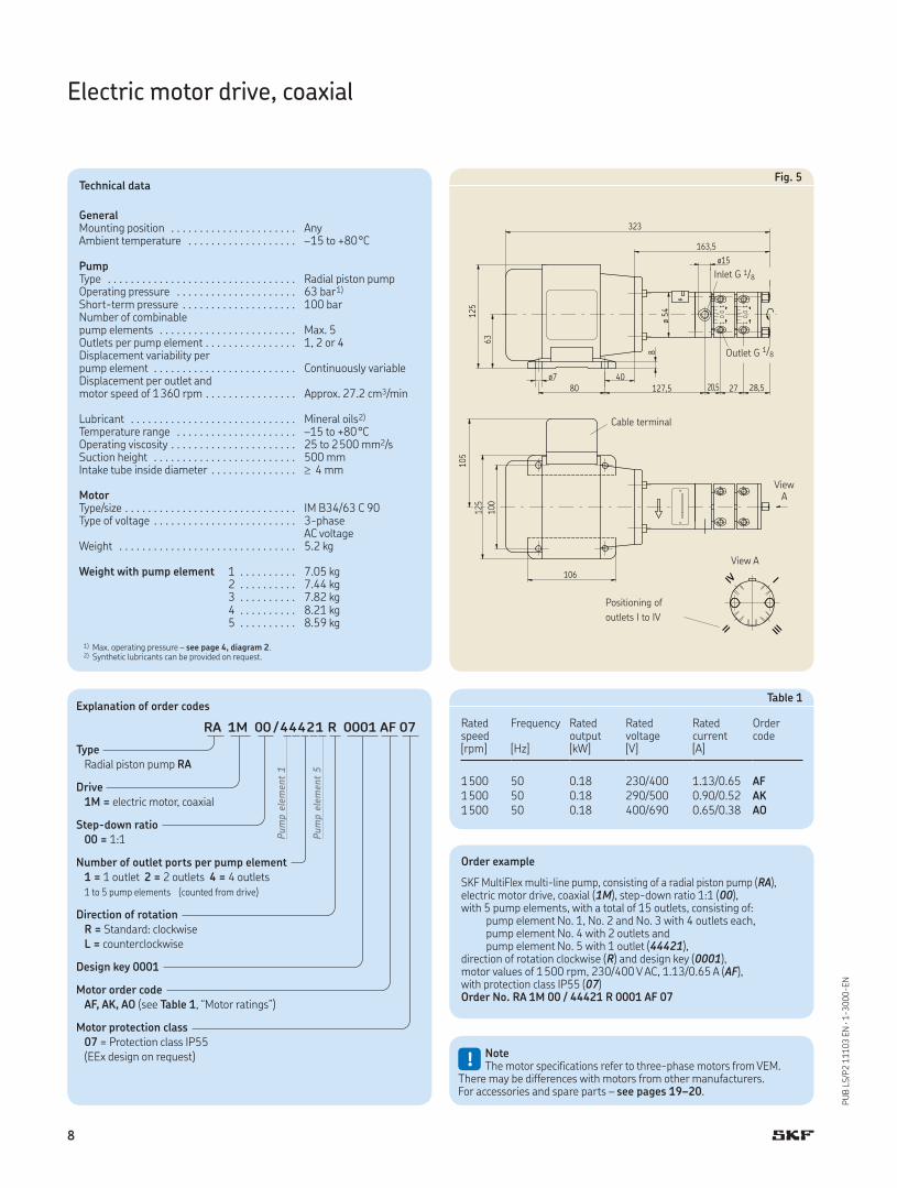
Electric motor drive, coaxial
Fig. 5Technical data
GeneralMounting position . . . . . . . . . . . . . . . . . . . . . . AnyAmbient temperature . . . . . . . . . . . . . . . . . . . –15 to +80°C
PumpType . . . . . . . . . . . . . . . . . . . . . . . . . . . . . . . . . Radial piston pumpOperating pressure . . . . . . . . . . . . . . . . . . . . . 63 bar1)
Short-term pressure . . . . . . . . . . . . . . . . . . . . 100 barNumber of combinable pump elements . . . . . . . . . . . . . . . . . . . . . . . . Max. 5Outlets per pump element . . . . . . . . . . . . . . . . 1, 2 or 4Displacement variability per pump element . . . . . . . . . . . . . . . . . . . . . . . . . Continuously variableDisplacement per outlet and motor speed of 1360 rpm . . . . . . . . . . . . . . . . Approx. 27.2 cm3/min
Lubricant . . . . . . . . . . . . . . . . . . . . . . . . . . . . . Mineral oils2)
Temperature range . . . . . . . . . . . . . . . . . . . . . –15 to +80°COperating viscosity . . . . . . . . . . . . . . . . . . . . . . 25 to 2500 mm2/sSuction height . . . . . . . . . . . . . . . . . . . . . . . . . 500 mmIntake tube inside diameter . . . . . . . . . . . . . . . 4 mm
MotorType/size . . . . . . . . . . . . . . . . . . . . . . . . . . . . . . IM B34/63 C 90Type of voltage . . . . . . . . . . . . . . . . . . . . . . . . . 3-phase
AC voltageWeight . . . . . . . . . . . . . . . . . . . . . . . . . . . . . . . 5.2 kg
Weight with pump element 1 . . . . . . . . . . 7.05 kg 2 . . . . . . . . . . 7.44 kg 3 . . . . . . . . . . 7.82 kg 4 . . . . . . . . . . 8.21 kg 5 . . . . . . . . . . 8.59 kg
1) Max. operating pressure – see page 4, diagram 2.2) Synthetic lubricants can be provided on request.
Inlet G 1/8
Outlet G 1/8
View A
View A
Cable terminal
Positioning of
outlets I to IV
Table 1
Ratedspeed
Frequency Ratedoutput
Ratedvoltage
Ratedcurrent
Order code
[rpm] [Hz] [kW] [V] [A]
1500 50 0.18 230/400 1.13/0.65 AF1500 50 0.18 290/500 0.90/0.52 AK1500 50 0.18 400/690 0.65/0.38 AO
Order example
SKF MultiFlex multi-line pump, consisting of a radial piston pump (RA), electric motor drive, coaxial (1M), step-down ratio 1:1 (00), with 5 pump elements, with a total of 15 outlets, consisting of: pump element No. 1, No. 2 and No. 3 with 4 outlets each, pump element No. 4 with 2 outlets and pump element No. 5 with 1 outlet (44421), direction of rotation clockwise (R) and design key (0001), motor values of 1500 rpm, 230/400 V AC, 1.13/0.65 A (AF), with protection class IP55 (07)Order No. RA 1M 00 / 44421 R 0001 AF 07
!NoteThe motor specifications refer to three-phase motors from VEM.
There may be differences with motors from other manufacturers.For accessories and spare parts – see pages 19–20.
Explanation of order codes
RA 1M 00 / 44421 R 0001 AF 07
Type
Radial piston pump RA
Drive
1M = electric motor, coaxial
Step-down ratio
00 = 1:1
Number of outlet ports per pump element
1 = 1 outlet 2 = 2 outlets 4 = 4 outlets1 to 5 pump elements (counted from drive)
Direction of rotation
R = Standard: clockwiseL = counterclockwise
Design key 0001
Motor order code
AF, AK, AO (see Table 1, “Motor ratings”)
Motor protection class
07 = Protection class IP55(EEx design on request)
Pum
p e
lem
ent
1
Pum
p e
lem
ent
5
8
PU
B L
S/P
2 1
11
03
EN
· 1
-30
00
-EN
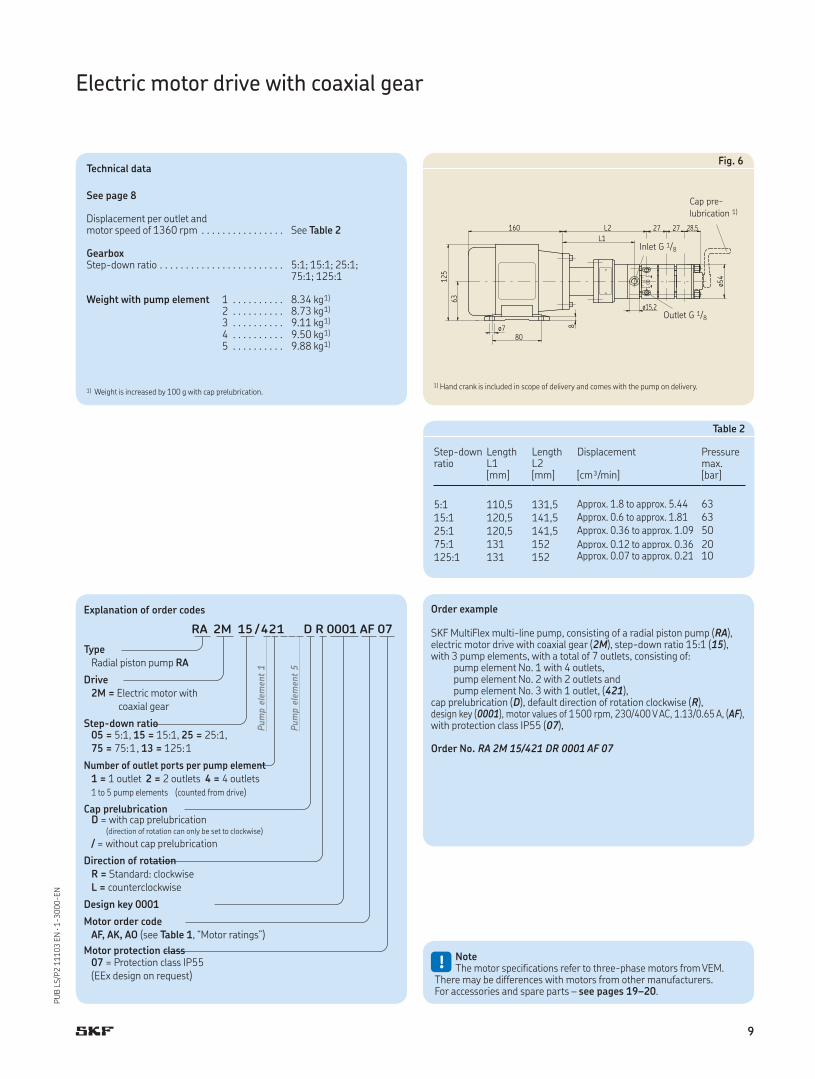
Electric motor drive with coaxial gear
Fig. 6
Outlet G 1/8
Inlet G 1/8
Cap pre-
lubrication 1)
Technical data
See page 8
Displacement per outlet and motor speed of 1360 rpm . . . . . . . . . . . . . . . . See Table 2
GearboxStep-down ratio . . . . . . . . . . . . . . . . . . . . . . . . 5:1; 15:1; 25:1;
75:1; 125:1
Weight with pump element 1 . . . . . . . . . . 8.34 kg1)
2 . . . . . . . . . . 8.73 kg1)
3 . . . . . . . . . . 9.11 kg1)
4 . . . . . . . . . . 9.50 kg1)
5 . . . . . . . . . . 9.88 kg1)
1) Weight is increased by 100 g with cap prelubrication.
Order example
SKF MultiFlex multi-line pump, consisting of a radial piston pump (RA), electric motor drive with coaxial gear (2M), step-down ratio 15:1 (15), with 3 pump elements, with a total of 7 outlets, consisting of: pump element No. 1 with 4 outlets, pump element No. 2 with 2 outlets and pump element No. 3 with 1 outlet, (421), cap prelubrication (D), default direction of rotation clockwise (R), design key (0001), motor values of 1500 rpm, 230/400 V AC, 1.13/0.65 A, (AF), with protection class IP55 (07),
Order No. RA 2M 15/421 DR 0001 AF 07
1) Hand crank is included in scope of delivery and comes with the pump on delivery.
!NoteThe motor specifications refer to three-phase motors from VEM.
There may be differences with motors from other manufacturers.For accessories and spare parts – see pages 19–20.
Explanation of order codes
RA 2M 15 / 421 D R 0001 AF 07
Type
Radial piston pump RA
Drive
2M = Electric motor with coaxial gear
Step-down ratio05 = 5:1, 15 = 15:1, 25 = 25:1,75 = 75:1, 13 = 125:1
Number of outlet ports per pump element
1 = 1 outlet 2 = 2 outlets 4 = 4 outlets1 to 5 pump elements (counted from drive)
Cap prelubricationD = with cap prelubrication (direction of rotation can only be set to clockwise)
/ = without cap prelubrication
Direction of rotation
R = Standard: clockwiseL = counterclockwise
Design key 0001
Motor order code
AF, AK, AO (see Table 1, “Motor ratings”)
Motor protection class07 = Protection class IP55(EEx design on request)
Pum
p e
lem
ent
1
Pum
p e
lem
ent
5
Table 2
Step-down ratio
LengthL1
LengthL2
Displacement Pressuremax.
[mm] [mm] [cm³/min] [bar]
5:1 110,5 131,5 Approx. 1.8 to approx. 5.44 63
15:1 120,5 141,5 Approx. 0.6 to approx. 1.81 63
25:1 120,5 141,5 Approx. 0.36 to approx. 1.09 50
75:1 131 152 Approx. 0.12 to approx. 0.36 20125:1 131 152 Approx. 0.07 to approx. 0.21 10
9
PU
B L
S/P
2 1
11
03
EN
· 1
-30
00
-EN
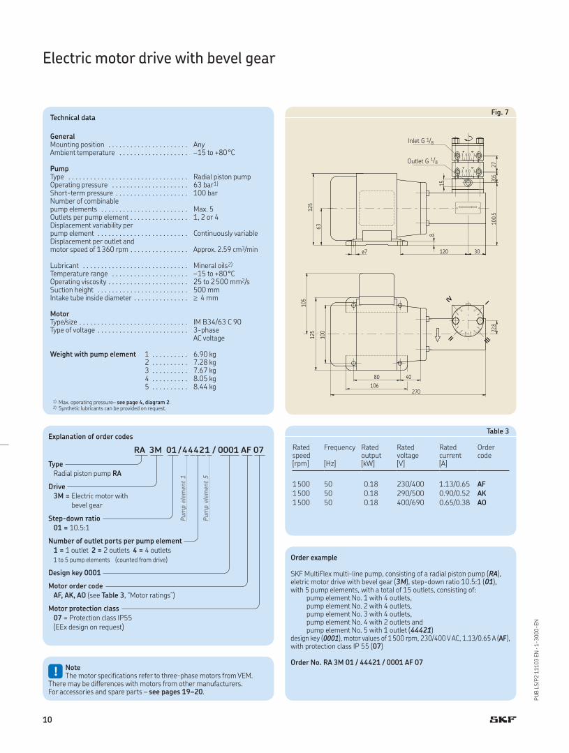
Electric motor drive with bevel gear
Fig. 7Technical data
GeneralMounting position . . . . . . . . . . . . . . . . . . . . . . AnyAmbient temperature . . . . . . . . . . . . . . . . . . . –15 to +80°C
PumpType . . . . . . . . . . . . . . . . . . . . . . . . . . . . . . . . . Radial piston pumpOperating pressure . . . . . . . . . . . . . . . . . . . . . 63 bar1)
Short-term pressure . . . . . . . . . . . . . . . . . . . . 100 barNumber of combinable pump elements . . . . . . . . . . . . . . . . . . . . . . . . Max. 5Outlets per pump element . . . . . . . . . . . . . . . . 1, 2 or 4Displacement variability per pump element . . . . . . . . . . . . . . . . . . . . . . . . . Continuously variableDisplacement per outlet and motor speed of 1360 rpm . . . . . . . . . . . . . . . . Approx. 2.59 cm3/min
Lubricant . . . . . . . . . . . . . . . . . . . . . . . . . . . . . Mineral oils2)
Temperature range . . . . . . . . . . . . . . . . . . . . . –15 to +80°COperating viscosity . . . . . . . . . . . . . . . . . . . . . . 25 to 2500 mm2/sSuction height . . . . . . . . . . . . . . . . . . . . . . . . . 500 mmIntake tube inside diameter . . . . . . . . . . . . . . . 4 mm
MotorType/size . . . . . . . . . . . . . . . . . . . . . . . . . . . . . . IM B34/63 C 90Type of voltage . . . . . . . . . . . . . . . . . . . . . . . . . 3-phase
AC voltage
Weight with pump element 1 . . . . . . . . . . 6.90 kg 2 . . . . . . . . . . 7.28 kg 3 . . . . . . . . . . 7.67 kg 4 . . . . . . . . . . 8.05 kg 5 . . . . . . . . . . 8.44 kg
1) Max. operating pressure– see page 4, diagram 2.2) Synthetic lubricants can be provided on request.
Inlet G 1/8
Outlet G 1/8
Table 3
Ratedspeed
Frequency Ratedoutput
Ratedvoltage
Ratedcurrent
Order code
[rpm] [Hz] [kW] [V] [A]
1500 50 0.18 230/400 1.13/0.65 AF1500 50 0.18 290/500 0.90/0.52 AK1500 50 0.18 400/690 0.65/0.38 AO
Order example
SKF MultiFlex multi-line pump, consisting of a radial piston pump (RA), eletric motor drive with bevel gear (3M), step-down ratio 10.5:1 (01), with 5 pump elements, with a total of 15 outlets, consisting of: pump element No. 1 with 4 outlets, pump element No. 2 with 4 outlets, pump element No. 3 with 4 outlets, pump element No. 4 with 2 outlets and pump element No. 5 with 1 outlet (44421)design key (0001), motor values of 1500 rpm, 230/400 V AC, 1.13/0.65 A (AF), with protection class IP 55 (07)
Order No. RA 3M 01 / 44421 / 0001 AF 07
!NoteThe motor specifications refer to three-phase motors from VEM.
There may be differences with motors from other manufacturers.For accessories and spare parts – see pages 19–20.
Explanation of order codes
RA 3M 01 / 44421 / 0001 AF 07
Type
Radial piston pump RA
Drive
3M = Electric motor with bevel gear
Step-down ratio
01 = 10.5:1
Number of outlet ports per pump element
1 = 1 outlet 2 = 2 outlets 4 = 4 outlets1 to 5 pump elements (counted from drive)
Design key 0001
Motor order code
AF, AK, AO (see Table 3, “Motor ratings”)
Motor protection class
07 = Protection class IP55(EEx design on request)
Pum
p e
lem
ent
1
Pum
p e
lem
ent
5
10
PU
B L
S/P
2 1
11
03
EN
· 1
-30
00
-EN
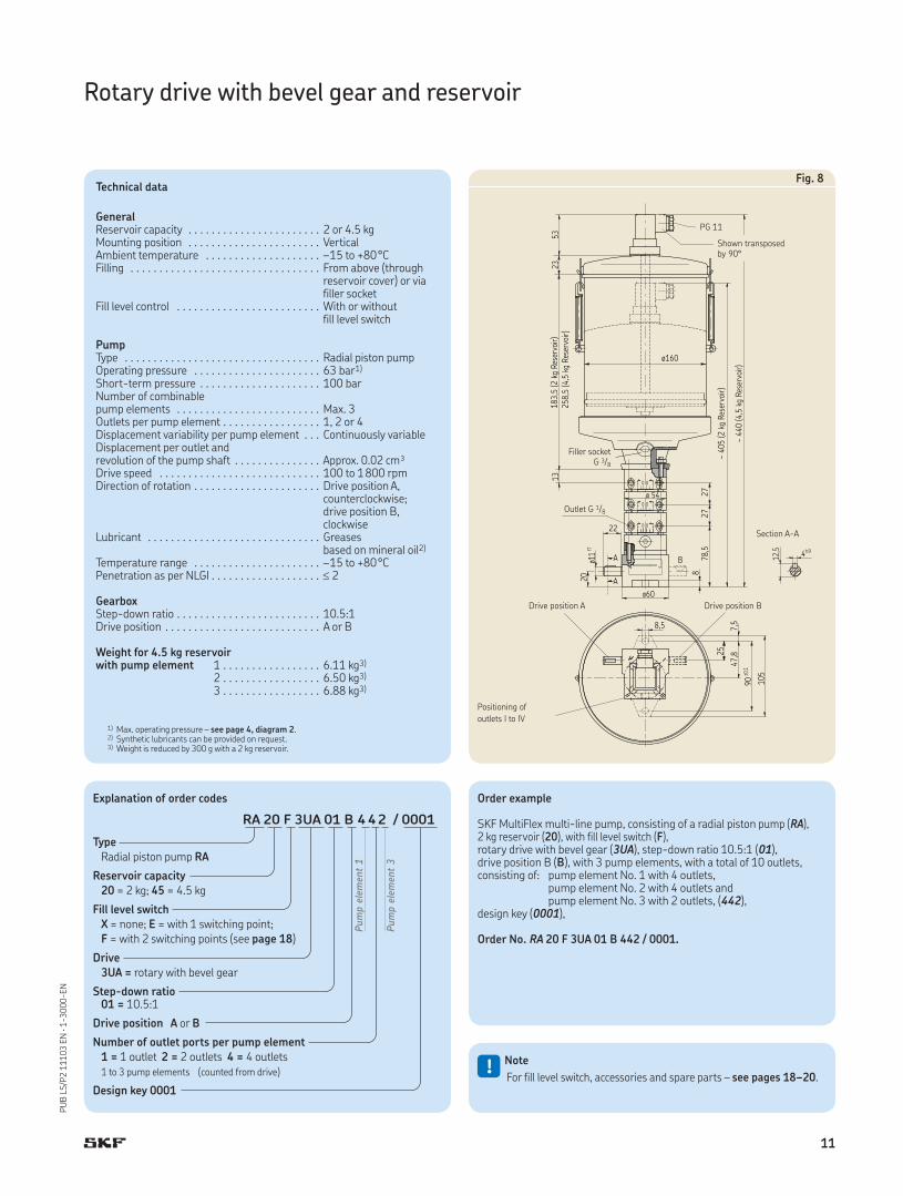
Rotary drive with bevel gear and reservoir
Fig. 8Technical data
GeneralReservoir capacity . . . . . . . . . . . . . . . . . . . . . . . 2 or 4.5 kgMounting position . . . . . . . . . . . . . . . . . . . . . . . VerticalAmbient temperature . . . . . . . . . . . . . . . . . . . . –15 to +80°CFilling . . . . . . . . . . . . . . . . . . . . . . . . . . . . . . . . . From above (through
reservoir cover) or viafiller socket
Fill level control . . . . . . . . . . . . . . . . . . . . . . . . . With or without fill level switch
PumpType . . . . . . . . . . . . . . . . . . . . . . . . . . . . . . . . . . Radial piston pumpOperating pressure . . . . . . . . . . . . . . . . . . . . . . 63 bar1)
Short-term pressure . . . . . . . . . . . . . . . . . . . . . 100 barNumber of combinable pump elements . . . . . . . . . . . . . . . . . . . . . . . . . Max. 3Outlets per pump element . . . . . . . . . . . . . . . . . 1, 2 or 4Displacement variability per pump element . . . Continuously variableDisplacement per outlet and revolution of the pump shaft . . . . . . . . . . . . . . . Approx. 0.02 cm³Drive speed . . . . . . . . . . . . . . . . . . . . . . . . . . . . 100 to 1800 rpmDirection of rotation . . . . . . . . . . . . . . . . . . . . . . Drive position A,
counterclockwise;drive position B, clockwise
Lubricant . . . . . . . . . . . . . . . . . . . . . . . . . . . . . . Greases based on mineral oil2)
Temperature range . . . . . . . . . . . . . . . . . . . . . . –15 to +80°CPenetration as per NLGI . . . . . . . . . . . . . . . . . . . 2
GearboxStep-down ratio . . . . . . . . . . . . . . . . . . . . . . . . . 10.5:1Drive position . . . . . . . . . . . . . . . . . . . . . . . . . . . A or B
Weight for 4.5 kg reservoirwith pump element 1 . . . . . . . . . . . . . . . . . 6.11 kg3)
2 . . . . . . . . . . . . . . . . . 6.50 kg3)
3 . . . . . . . . . . . . . . . . . 6.88 kg3)
1) Max. operating pressure – see page 4, diagram 2.2) Synthetic lubricants can be provided on request.3) Weight is reduced by 300 g with a 2 kg reservoir.
Positioning of
outlets I to IV
Section A-A
Drive position A Drive position B
Outlet G 1/8
Filler socket G 3/8
Shown transposedby 90°
PG 11
Order example
SKF MultiFlex multi-line pump, consisting of a radial piston pump (RA), 2 kg reservoir (20), with fill level switch (F), rotary drive with bevel gear (3UA), step-down ratio 10.5:1 (01), drive position B (B), with 3 pump elements, with a total of 10 outlets, consisting of: pump element No. 1 with 4 outlets, pump element No. 2 with 4 outlets and pump element No. 3 with 2 outlets, (442), design key (0001),
Order No. RA 20 F 3UA 01 B 442 / 0001.
!Note
For fill level switch, accessories and spare parts – see pages 18–20.
Explanation of order codes
RA 20 F 3UA 01 B 442 / 0001
Type
Radial piston pump RA
Reservoir capacity
20 = 2 kg; 45 = 4.5 kg
Fill level switch
X = none; E = with 1 switching point; F = with 2 switching points (see page 18)
Drive
3UA = rotary with bevel gear
Step-down ratio01 = 10.5:1
Drive position A or B
Number of outlet ports per pump element
1 = 1 outlet 2 = 2 outlets 4 = 4 outlets1 to 3 pump elements (counted from drive)
Design key 0001
Pum
p e
lem
ent
1
Pum
p e
lem
ent
3
11
PU
B L
S/P
2 1
11
03
EN
· 1
-30
00
-EN
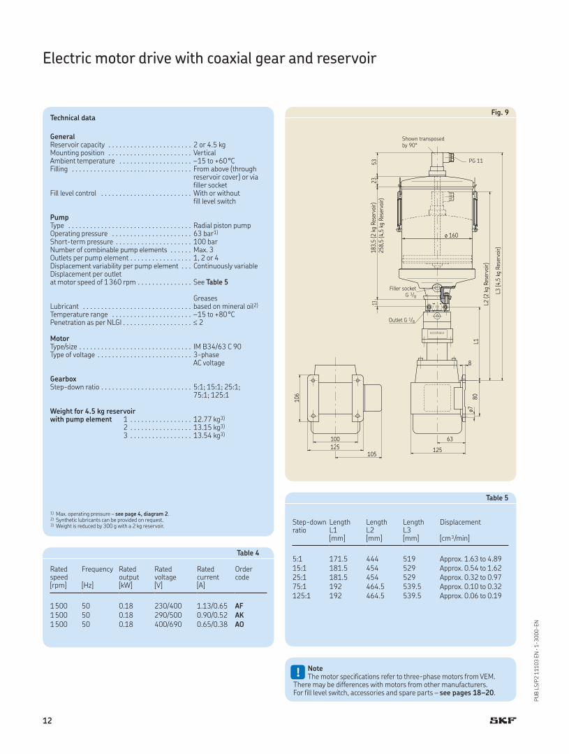
Electric motor drive with coaxial gear and reservoir
Technical data
GeneralReservoir capacity . . . . . . . . . . . . . . . . . . . . . . . 2 or 4.5 kgMounting position . . . . . . . . . . . . . . . . . . . . . . . VerticalAmbient temperature . . . . . . . . . . . . . . . . . . . . –15 to +60°CFilling . . . . . . . . . . . . . . . . . . . . . . . . . . . . . . . . . From above (through
reservoir cover) or viafiller socket
Fill level control . . . . . . . . . . . . . . . . . . . . . . . . . With or without fill level switch
PumpType . . . . . . . . . . . . . . . . . . . . . . . . . . . . . . . . . . Radial piston pumpOperating pressure . . . . . . . . . . . . . . . . . . . . . . 63 bar1)
Short-term pressure . . . . . . . . . . . . . . . . . . . . . 100 barNumber of combinable pump elements . . . . . . Max. 3Outlets per pump element . . . . . . . . . . . . . . . . . 1, 2 or 4Displacement variability per pump element . . . Continuously variableDisplacement per outlet at motor speed of 1360 rpm . . . . . . . . . . . . . . . See Table 5
Lubricant . . . . . . . . . . . . . . . . . . . . . . . . . . . . . .Greases based on mineral oil2)
Temperature range . . . . . . . . . . . . . . . . . . . . . . –15 to +80°CPenetration as per NLGI . . . . . . . . . . . . . . . . . . . 2
MotorType/size . . . . . . . . . . . . . . . . . . . . . . . . . . . . . . . IM B34/63 C 90Type of voltage . . . . . . . . . . . . . . . . . . . . . . . . . . 3-phase
AC voltage
GearboxStep-down ratio . . . . . . . . . . . . . . . . . . . . . . . . . 5:1; 15:1; 25:1;
75:1; 125:1
Weight for 4.5 kg reservoirwith pump element 1 . . . . . . . . . . . . . . . . . 12.77 kg3)
2 . . . . . . . . . . . . . . . . . 13.15 kg3)
3 . . . . . . . . . . . . . . . . . 13.54 kg3)
1) Max. operating pressure – see page 4, diagram 2.2) Synthetic lubricants can be provided on request.3) Weight is reduced by 300 g with a 2 kg reservoir.
Table 4
Ratedspeed
Frequency Ratedoutput
Ratedvoltage
Ratedcurrent
Order code
[rpm] [Hz] [kW] [V] [A]
1500 50 0.18 230/400 1.13/0.65 AF1500 50 0.18 290/500 0.90/0.52 AK1500 50 0.18 400/690 0.65/0.38 AO
Fig. 9
Table 5
Step-downratio
LengthL1
LengthL2
LengthL3
Displacement
[mm] [mm] [mm] [cm³/min]
5:1 171.5 444 519 Approx. 1.63 to 4.8915:1 181.5 454 529 Approx. 0.54 to 1.6225:1 181.5 454 529 Approx. 0.32 to 0.9775:1 192 464.5 539.5 Approx. 0.10 to 0.32125:1 192 464.5 539.5 Approx. 0.06 to 0.19
Outlet G 1/8
Filler socket G 3/8
Shown transposedby 90°
PG 11
!NoteThe motor specifications refer to three-phase motors from VEM.
There may be differences with motors from other manufacturers.For fill level switch, accessories and spare parts – see pages 18–20.
12
PU
B L
S/P
2 1
11
03
EN
· 1
-30
00
-EN
Electric motor drive with coaxial gear and reservoir
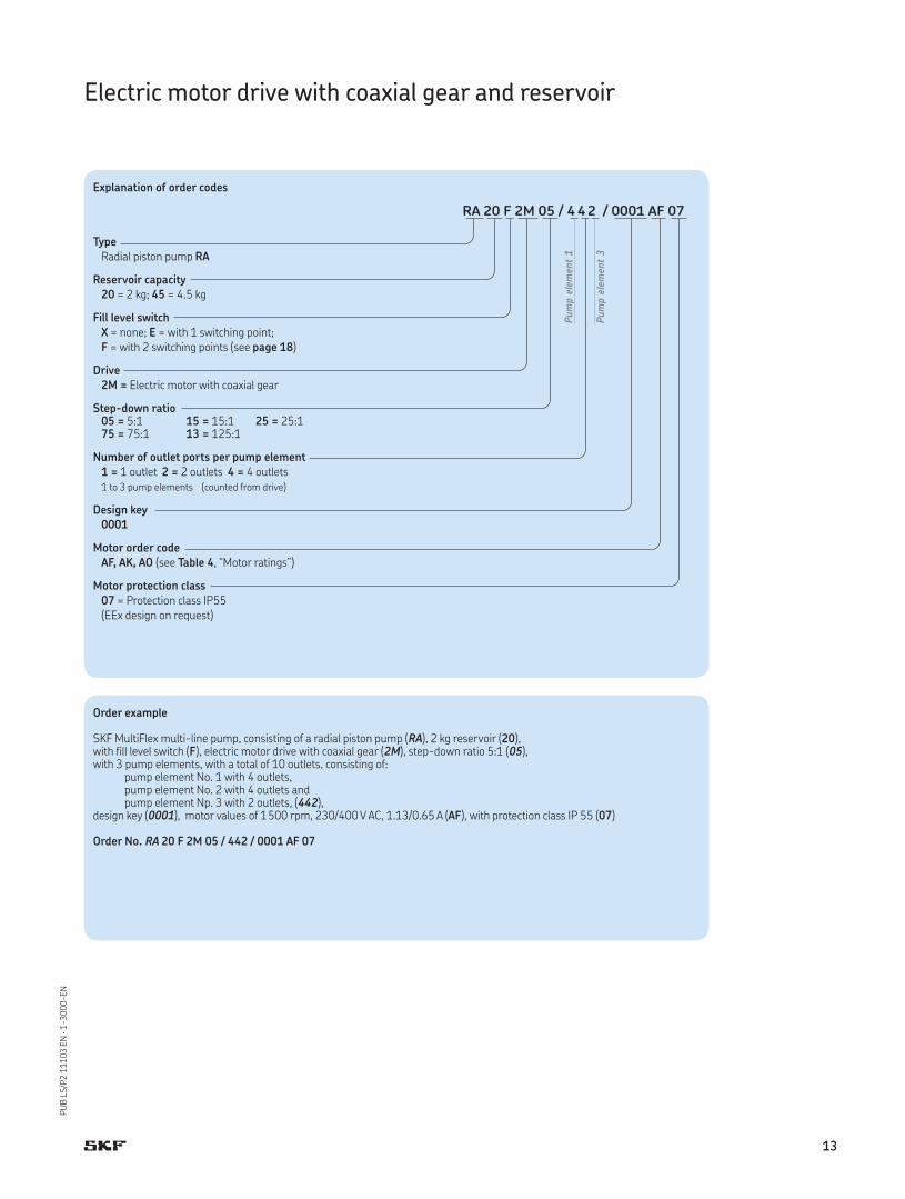
Order example
SKF MultiFlex multi-line pump, consisting of a radial piston pump (RA), 2 kg reservoir (20), with fill level switch (F), electric motor drive with coaxial gear (2M), step-down ratio 5:1 (05), with 3 pump elements, with a total of 10 outlets, consisting of: pump element No. 1 with 4 outlets, pump element No. 2 with 4 outlets and pump element Np. 3 with 2 outlets, (442), design key (0001), motor values of 1500 rpm, 230/400 V AC, 1.13/0.65 A (AF), with protection class IP 55 (07)
Order No. RA 20 F 2M 05 / 442 / 0001 AF 07
Explanation of order codes
RA 20 F 2M 05 / 442 / 0001 AF 07
Type
Radial piston pump RA
Reservoir capacity
20 = 2 kg; 45 = 4.5 kg
Fill level switch
X = none; E = with 1 switching point; F = with 2 switching points (see page 18)
Drive
2M = Electric motor with coaxial gear
Step-down ratio05 = 5:1 15 = 15:1 25 = 25:175 = 75:1 13 = 125:1
Number of outlet ports per pump element
1 = 1 outlet 2 = 2 outlets 4 = 4 outlets1 to 3 pump elements (counted from drive)
Design key
0001
Motor order code
AF, AK, AO (see Table 4, “Motor ratings”)
Motor protection class
07 = Protection class IP55(EEx design on request)
Pum
p e
lem
ent
1
Pum
p e
lem
ent
3
13
PU
B L
S/P
2 1
11
03
EN
· 1
-30
00
-EN
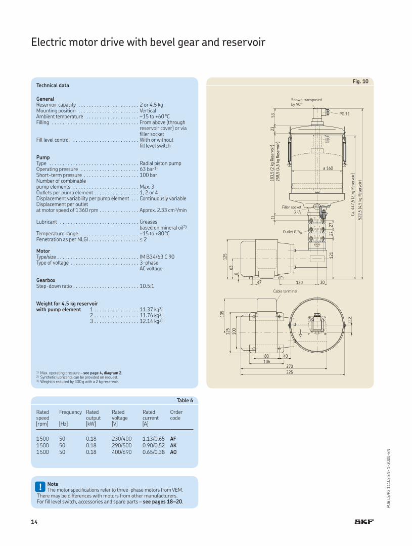
Technical data
GeneralReservoir capacity . . . . . . . . . . . . . . . . . . . . . . . 2 or 4.5 kgMounting position . . . . . . . . . . . . . . . . . . . . . . . VerticalAmbient temperature . . . . . . . . . . . . . . . . . . . . –15 to +60°CFilling . . . . . . . . . . . . . . . . . . . . . . . . . . . . . . . . . From above (through
reservoir cover) or viafiller socket
Fill level control . . . . . . . . . . . . . . . . . . . . . . . . . With or without fill level switch
PumpType . . . . . . . . . . . . . . . . . . . . . . . . . . . . . . . . . . Radial piston pumpOperating pressure . . . . . . . . . . . . . . . . . . . . . . 63 bar1)
Short-term pressure . . . . . . . . . . . . . . . . . . . . . 100 barNumber of combinable pump elements . . . . . . . . . . . . . . . . . . . . . . . . . Max. 3Outlets per pump element . . . . . . . . . . . . . . . . . 1, 2 or 4Displacement variability per pump element . . . Continuously variableDisplacement per outlet at motor speed of 1360 rpm . . . . . . . . . . . . . . . Approx. 2.33 cm³/min
Lubricant . . . . . . . . . . . . . . . . . . . . . . . . . . . . . . Greases based on mineral oil2)
Temperature range . . . . . . . . . . . . . . . . . . . . . . –15 to +80°CPenetration as per NLGI . . . . . . . . . . . . . . . . . . . 2
MotorType/size . . . . . . . . . . . . . . . . . . . . . . . . . . . . . . . IM B34/63 C 90Type of voltage . . . . . . . . . . . . . . . . . . . . . . . . . . 3-phase
AC voltage
GearboxStep-down ratio . . . . . . . . . . . . . . . . . . . . . . . . . 10.5:1
Weight for 4.5 kg reservoirwith pump element 1 . . . . . . . . . . . . . . . . . 11.37 kg3)
2 . . . . . . . . . . . . . . . . . 11.76 kg3)
3 . . . . . . . . . . . . . . . . . 12.14 kg3)
1) Max. operating pressure – see page 4, diagram 2.2) Synthetic lubricants can be provided on request.3) Weight is reduced by 300 g with a 2 kg reservoir.
Table 6
Ratedspeed
Frequency Ratedoutput
Ratedvoltage
Ratedcurrent
Order code
[rpm] [Hz] [kW] [V] [A]
1500 50 0.18 230/400 1.13/0.65 AF1500 50 0.18 290/500 0.90/0.52 AK1500 50 0.18 400/690 0.65/0.38 AO
Fig. 10
Outlet G 1/8
Filler socket G 3/8
Shown transposedby 90°
PG 11
Electric motor drive with bevel gear and reservoir
Cable terminal
!NoteThe motor specifications refer to three-phase motors from VEM.
There may be differences with motors from other manufacturers.For fill level switch, accessories and spare parts – see pages 18–20.
14
PU
B L
S/P
2 1
11
03
EN
· 1
-30
00
-EN
Electric motor drive with bevel gear and reservoir
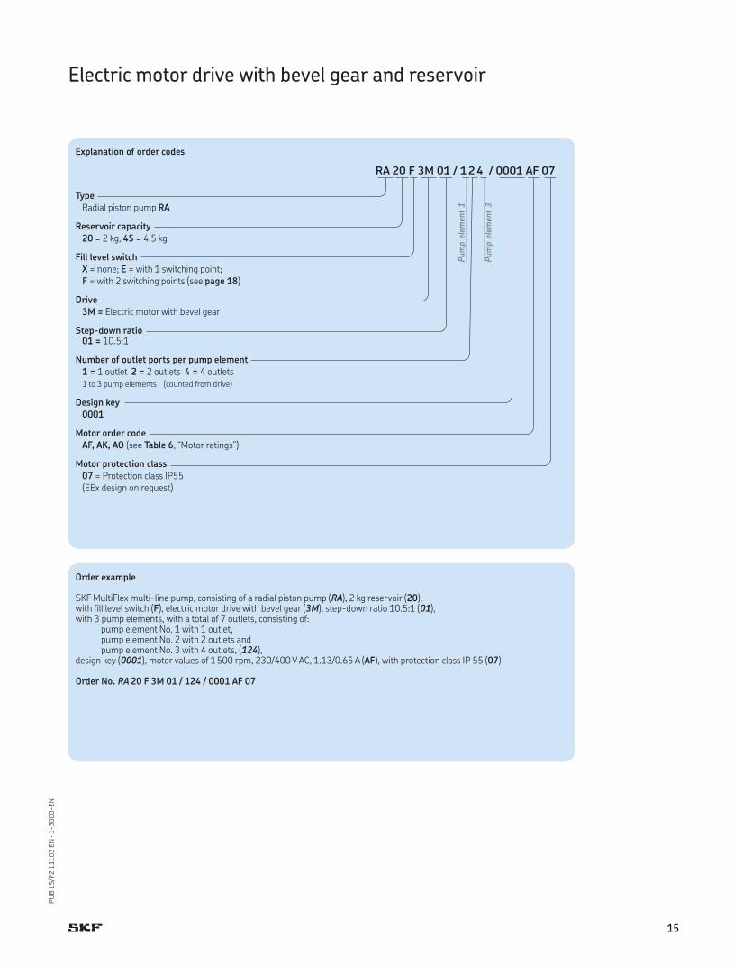
Order example
SKF MultiFlex multi-line pump, consisting of a radial piston pump (RA), 2 kg reservoir (20), with fill level switch (F), electric motor drive with bevel gear (3M), step-down ratio 10.5:1 (01), with 3 pump elements, with a total of 7 outlets, consisting of: pump element No. 1 with 1 outlet, pump element No. 2 with 2 outlets and pump element No. 3 with 4 outlets, (124), design key (0001), motor values of 1500 rpm, 230/400 V AC, 1.13/0.65 A (AF), with protection class IP 55 (07)
Order No. RA 20 F 3M 01 / 124 / 0001 AF 07
Explanation of order codes
RA 20 F 3M 01 / 124 / 0001 AF 07
Type
Radial piston pump RA
Reservoir capacity
20 = 2 kg; 45 = 4.5 kg
Fill level switch
X = none; E = with 1 switching point; F = with 2 switching points (see page 18)
Drive
3M = Electric motor with bevel gear
Step-down ratio01 = 10.5:1
Number of outlet ports per pump element
1 = 1 outlet 2 = 2 outlets 4 = 4 outlets1 to 3 pump elements (counted from drive)
Design key
0001
Motor order code
AF, AK, AO (see Table 6, “Motor ratings”)
Motor protection class
07 = Protection class IP55(EEx design on request)
Pum
p e
lem
ent
1
Pum
p e
lem
ent
3
15
PU
B L
S/P
2 1
11
03
EN
· 1
-30
00
-EN
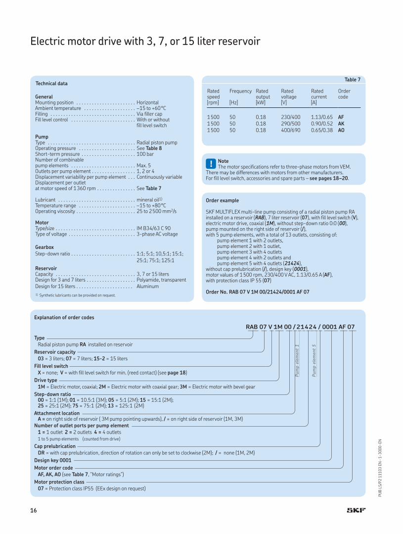
Electric motor drive with 3, 7, or 15 liter reservoir
Technical data
GeneralMounting position . . . . . . . . . . . . . . . . . . . . . . . HorizontalAmbient temperature . . . . . . . . . . . . . . . . . . . . –15 to +60°CFilling . . . . . . . . . . . . . . . . . . . . . . . . . . . . . . . . . Via filler capFill level control . . . . . . . . . . . . . . . . . . . . . . . . . With or without
fill level switch
PumpType . . . . . . . . . . . . . . . . . . . . . . . . . . . . . . . . . . Radial piston pumpOperating pressure . . . . . . . . . . . . . . . . . . . . . . See Table 8Short-term pressure . . . . . . . . . . . . . . . . . . . . . 100 barNumber of combinable pump elements . . . . . . . . . . . . . . . . . . . . . . . . . Max. 5Outlets per pump element . . . . . . . . . . . . . . . . . 1, 2 or 4Displacement variability per pump element . . . Continuously variableDisplacement per outlet at motor speed of 1360 rpm . . . . . . . . . . . . . . . See Table 7
Lubricant . . . . . . . . . . . . . . . . . . . . . . . . . . . . . . mineral oil1)
Temperature range . . . . . . . . . . . . . . . . . . . . . . –15 to +80°COperating viscosity . . . . . . . . . . . . . . . . . . . . . . . 25 to 2500 mm2/s
MotorType/size . . . . . . . . . . . . . . . . . . . . . . . . . . . . . . . IM B34/63 C 90Type of voltage . . . . . . . . . . . . . . . . . . . . . . . . . . 3-phase AC voltage
Gearbox
1:1; 5:1; 10,5:1; 15:1; 25:1; 75:1; 125:1
Step-down ratio . . . . . . . . . . . . . . . . . . . . . . . . .
ReservoirCapacity . . . . . . . . . . . . . . . . . . . . . . . . . . . . . . . 3, 7 or 15 litersDesign for 3 and 7 liters . . . . . . . . . . . . . . . . . . . Polyamide, transparentDesign for 15 liters . . . . . . . . . . . . . . . . . . . . . . Aluminum
1) Synthetic lubricants can be provided on request.
Table 7
Ratedspeed
Frequency Ratedoutput
Ratedvoltage
Ratedcurrent
Order code
[rpm] [Hz] [kW] [V] [A]
1500 50 0.18 230/400 1.13/0.65 AF1500 50 0.18 290/500 0.90/0.52 AK1500 50 0.18 400/690 0.65/0.38 AO
Order example
SKF MULTIFLEX multi-line pump consisting of a radial piston pump RA installed on a reservoir (RAB), 7 liter reservoir (07), with fill level switch (V), electric motor drive, coaxial (1M), without step-down ratio 0:0 (00), pump mounted on the right side of reservoir (/), with 5 pump elements, with a total of 13 outlets, consisting of: pump element 1 with 2 outlets, pump element 2 with 1 outlet, pump element 3 with 4 outlets pump element 4 with 2 outlets and pump element 5 with 4 outlets (21424), without cap prelubrication (/), design key (0001), motor values of 1500 rpm, 230/400 V AC, 1.13/0.65 A (AF), with protection class IP 55 (07)
Order No. RAB 07 V 1M 00/21424/0001 AF 07
!NoteThe motor specifications refer to three-phase motors from VEM.
There may be differences with motors from other manufacturers.For fill level switch, accessories and spare parts – see pages 18–20.
Explanation of order codes
RAB 07 V 1M 00 / 21424 / 0001 AF 07
Type
Radial piston pump RA installed on reservoir
Reservoir capacity
03 = 3 liters; 07 = 7 liters; 15-2 = 15 liters
Fill level switch
X = none; V = with fill level switch for min. (reed contact) (see page 18)
Drive type
1M = Electric motor, coaxial; 2M = Electric motor with coaxial gear; 3M = Electric motor with bevel gear
Step-down ratio00 = 1:1 (1M); 01 = 10.5:1 (3M); 05 = 5:1 (2M); 15 = 15:1 (2M); 25 = 25:1 (2M); 75 = 75:1 (2M); 13 = 125:1 (2M)
Attachment locationA = on right side of reservoir ( 3M pump pointing upwards), / = on right side of reservoir (1M, 3M)
Number of outlet ports per pump element
1 = 1 outlet 2 = 2 outlets 4 = 4 outlets1 to 5 pump elements (counted from drive)
Cap prelubrication
DR = with cap prelubrication, direction of rotation can only be set to clockwise (2M); / = none (1M, 2M)
Design key 0001
Motor order code
AF, AK, AO (see Table 7, “Motor ratings”)
Motor protection class
07 = Protection class IP55 (EEx design on request)
Pum
p e
lem
ent
1
Pum
p e
lem
ent
5
16
PU
B L
S/P
2 1
11
03
EN
· 1
-30
00
-EN
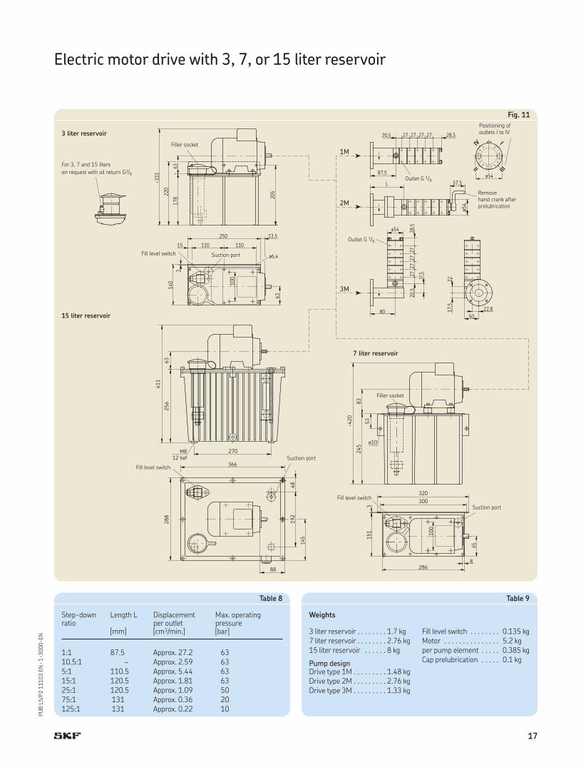
Fig. 11
178
63
110
140
3
15
ø6,4
100
110
13,5250
80
20,5
17,5
50
2237
,5
ø54
27
27
27
27
28,5
ø54
~333
220
63
205
L 57,5
87,5ø54
2720,5 27 2727 28,5
II
IV
III
I
22,8
ø10
151
3
245
~420
83
53
286
100
300
320
8
411
288
256
88
192
48
270
366
63
651
45
M812 tief
1M
2M
3M
Outlet G 1/8
Positioning of outlets I to IV
Removehand crank after prelubrication
For 3, 7 and 15 liters
on request with oil return G3/8
Outlet G 1/8
Filler socket
Suction portFill level switch
Electric motor drive with 3, 7, or 15 liter reservoir
Filler socket
Suction port
Fill level switch
Suction port
Fill level switch
3 liter reservoir
7 liter reservoir
15 liter reservoir
Table 8
Step-down ratio
Length L Displacementper outlet
Max. operating pressure
[mm] [cm3/min.] [bar]
1:1 87.5 Approx. 27.2 6310.5:1 – Approx. 2.59 635:1 110.5 Approx. 5.44 6315:1 120.5 Approx. 1.81 6325:1 120.5 Approx. 1.09 5075:1 131 Approx. 0.36 20125:1 131 Approx. 0.22 10
Table 9
Weights
3 liter reservoir . . . . . . . . 1.7 kg Fill level switch . . . . . . . . 0.135 kg7 liter reservoir . . . . . . . . 2.76 kg Motor . . . . . . . . . . . . . . . 5.2 kg15 liter reservoir . . . . . . 8 kg per pump element . . . . . 0.385 kg
Pump designCap prelubrication . . . . . 0.1 kg
Drive type 1M . . . . . . . . . 1.48 kgDrive type 2M . . . . . . . . . 2.76 kgDrive type 3M . . . . . . . . . 1.33 kg
17
PU
B L
S/P
2 1
11
03
EN
· 1
-30
00
-EN
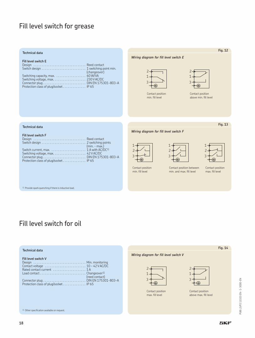
Contact position
min. fill level
Contact position
above min. fill level
Contact position
min. fill level
Contact position between
min. and max. fill level
Contact position
max. fill level
Contact position
max. fill level
Contact position
above max. fill level
Fill level switch for grease
Technical data
Fill level switch EDesign . . . . . . . . . . . . . . . . . . . . . . . . . . . . . . . . Reed contactSwitch design . . . . . . . . . . . . . . . . . . . . . . . . . . . 1 switching point min.
(changeover)Switching capacity, max. . . . . . . . . . . . . . . . . . . 60 W/VASwitching voltage, max. . . . . . . . . . . . . . . . . . . . 230 V AC/DCConnector plug . . . . . . . . . . . . . . . . . . . . . . . . . . DIN EN 175301-803-AProtection class of plug/socket . . . . . . . . . . . . . . IP 65
Technical data
Fill level switch FDesign . . . . . . . . . . . . . . . . . . . . . . . . . . . . . . . . Reed contactSwitch design . . . . . . . . . . . . . . . . . . . . . . . . . . . 2 switching points
(min. - max.)Switch current, max. . . . . . . . . . . . . . . . . . . . . . 1 A with AC/DC1)
Switching voltage, max. . . . . . . . . . . . . . . . . . . . 42 V AC/DCConnector plug . . . . . . . . . . . . . . . . . . . . . . . . . . DIN EN 175301-803-AProtection class of plug/socket . . . . . . . . . . . . . . IP 65
1) Provide spark quenching if there is inductive load.
Technical data
Fill level switch VDesign . . . . . . . . . . . . . . . . . . . . . . . . . . . . . . . . Min. monitoringContact voltage . . . . . . . . . . . . . . . . . . . . . . . . . 10 - 42 V AC/DCRated contact current . . . . . . . . . . . . . . . . . . . . 1 ALoad contact . . . . . . . . . . . . . . . . . . . . . . . . . . . . Changeover1)
(reed contact)Connector plug . . . . . . . . . . . . . . . . . . . . . . . . . . DIN EN 175301-803-AProtection class of plug/socket . . . . . . . . . . . . . . IP 65
1) Other specification available on request.
Fill level switch for oil
Fig. 12
Wiring diagram for fill level switch E
Fig. 13
Wiring diagram for fill level switch F
Fig. 14
Wiring diagram for fill level switch V
18
PU
B L
S/P
2 1
11
03
EN
· 1
-30
00
-EN
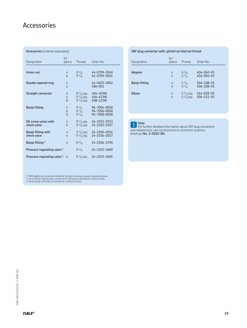
Accessories
Accessories (ordered separately)
Designationforpipe ø Thread Order No.
Union nut 4 R 1/8 44-0709-20406 R 1/8 44-0709-2041
Double tapered ring 4 44-0405-20026 406-001
Straight connector 4 R 1/8 tap. 404-403W6 R 1/8 tap. 406-423W8 R 1/8 tap. 408-423W
Banjo fitting 4 R 1/8 96-7004-00586 R 1/8 96-7006-00588 R 1/8 96-7008-0058
GE screw union withcheck valve
4 R 1/8 tap. 24-2103-29336 R 1/8 tap. 24-2103-2927
Banjo fitting with check valve
4 R 1/8 tap. 24-2106-20166 R 1/8 tap. 24-2106-2017
Banjo fitting1) 6 R 1/8 24-2106-2390
Pressure regulating valve2) R 1/8 24-2103-3680
Pressure regulating valve3) 6 R 1/8 tap. 24-2103-3681
1) With additional connection thread for directly screwing pressure regulating valves.2) Up to 90 bar, without pipe connection for RA pumps operated for short periods.3) Up to 60 bar, with pipe connection for continuous duty.
SKF plug connector with cylindrical internal thread
Designationforpipe ø Thread Order No.
Adapter 4 G 1/8 404-040-VS6 G 1/8 456-004-VS
Banjo fitting 4 G 1/8 504-108-VS6 G 1/8 506-108-VS
Elbow 4 G 1/8 tap. 514-018-VS6 G 1/8 tap. 506-511-VS
!NoteFor further detailed information about SKF plug connectors
and related tools, see our brochure on connector systems, brochure No. 1-0103-EN.
19
PU
B L
S/P
2 1
11
03
EN
· 1
-30
00
-EN
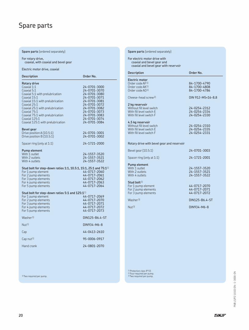
Spare parts
Spare parts (ordered separately)
For rotary drive, coaxial, with coaxial and bevel gear
Electric motor drive, coaxial
Description Order No.
Rotary driveCoaxial 1:1 24-0701-3000Coaxial 5:1 24-0701-3070Coaxial 5:1 with prelubrication 24-0701-3080Coaxial 15:1 24-0701-3071Coaxial 15:1 with prelubrication 24-0701-3081Coaxial 25:1 24-0701-3072Coaxial 25:1 with prelubrication 24-0701-3082Coaxial 75:1 24-0701-3073Coaxial 75:1 with prelubrication 24-0701-3083Coaxial 125:1 24-0701-3074Coaxial 125:1 with prelubrication 24-0701-3084
Bevel gearDrive position A (10.5:1) 24-0701-3001Drive position B (10.5:1) 24-0701-3002
Spacer ring (only at 1:1) 24-1721-2000
Pump elementWith 1 outlet 24-1557-3520With 2 outlets 24-1557-3521With 4 outlets 24-1557-3522
Stud bolt for step-down ratios 1:1, 10.5:1, 15:1, 25:1 and 75:11)
For 1 pump element 44-0717-2060For 2 pump elements 44-0717-2061For 3 pump elements 44-0717-2062For 4 pump elements 44-0717-2063For 5 pump elements 44-0717-2064
Stud bolt for step-down ratios 5:1 and 125:11)
For 1 pump element 44-0717-2069For 2 pump elements 44-0717-2070For 3 pump elements 44-0717-2071For 4 pump elements 44-0717-2072For 5 pump elements 44-0717-2073
Washer1) DIN125-B6.4-ST
Nut1) DIN934-M6-8
Cap 44-0413-2610
Cap nut1) 95-0006-0917
Hand crank 24-0801-2070
1) Two required per pump.
Spare parts (ordered separately)
For electric motor drive with coaxial and bevel gear and coaxial and bevel gear with reservoir
Description Order No.
Electric motorOrder code AF1) 84-1700-4790Order code AK1) 84-1700-4808Order code AO1) 84-1700-4786
Cheese-head screw2) DIN 912-M5×16-8.8
2 kg reservoirWithout fill level switch 24-0254-2312With fill level switch E 24-0254-2334With fill level switch F 24-0254-2330
4.5 kg reservoirWithout fill level switch 24-0254-2310With fill level switch E 24-0254-2335With fill level switch F 24-0254-2331
Rotary drive with bevel gear and reservoir
Bevel gear (10.5:1) 24-0701-3003
Spacer ring (only at 1:1) 24-1721-2001
Pump elementWith 1 outlet 24-1557-3520With 2 outlets 24-1557-3521With 4 outlets 24-1557-3522
Stud bolt3)
For 1 pump element 44-0717-2070For 2 pump elements 44-0717-2071For 3 pump elements 44-0717-2072
Washer3) DIN125-B6.4-ST
Nut3) DIN934-M6-8
1) Protection class IP 552) Four required per pump.3) Two required per pump.
20

PU
B L
S/P
2 1
11
03
EN
· 1
-30
00
-EN
Notes
21
PU
B L
S/P
2 1
11
03
EN
· 1
-30
00
-EN
Notes
22
PU
B L
S/P
2 1
11
03
EN
· 1
-30
00
-EN
Notes
23
!Important information on product usageSKF and Lincoln lubrication systems or their components are not approved for use with gases,
liquefied gases, pressurized gases in solution and fluids with a vapor pressure exceeding normal atmospheric pressure (1 013 mbar) by more than 0,5 bar at their maximum permissible temperature.
The Power of Knowledge Engineering
Combining products, people, and application-specific knowledge, SKF delivers innovative solutions to equipment manufacturers and production facilities in every major industry worldwide. Having expertise in multiple competence areas supports SKF Life Cycle Management, a proven approach to improving equipment reliability, optimizing operational and energy efficiency and reducing total cost of ownership.
These competence areas include bearings and units, seals, lubrication systems, mechatronics, and a wide range of services, from 3-D computer modelling to cloud-based condition monitoring and asset management services.
SKF’s global footprint provides SKF customers with uniform quality standards and worldwide product availability. Our local presence provides direct access to the experience, knowledge and ingenuity of SKF people.
SKF Lubrication Systems Germany GmbH
Hockenheim Plant
2. Industriestrasse 4
68766 Hockenheim
Germany
Tel. +49 (0)6205 27-0
Fax +49 (0)6205 27-100
This brochure was presented to you by:
Further brochures
1-0103-EN Fittings and Accessories
1-9201-EN Transport of Lubricants in Centralized Lubrication Systems
® SKF is a registered trademark of the SKF Group.
© SKF Group 2015The contents of this publication are the copyright of the publisher and may not be reproduced (even extracts) unless prior written permis-sion is granted. Every care has been taken to ensure the accuracy of the information contained in this publication but no liability can be accepted for any loss or damage whether direct, indirect or consequential arising out of the use of the information contained herein.
PUB LS/P2 11103 EN · August 2015 · 1-3000-EN
skf.com/lubrication