Embed Size (px)
Citation preview
International Journal of Reviews in Computing 31st July 2012. Vol. 10
© 2009 - 2012 IJRIC & LLS. All rights reserved.
ISSN: 2076-3328 www.ijric.org E-ISSN: 2076-3336
1
IJRIC
MULTI-LEVEL INVERTER: A LITERATURE SURVEY ON TOPOLOGIES AND CONTROL STRATEGIES
BINDESHWAR SINGH1 , NUPUR MITTAL 3 , DR. K.S. VERMA 2, DR. DEEPENDRA SINGH2 , S.P. SINGH1 , , RAHUL
DIXIT3, MANVENDRA SINGH3, AND AANCHAL BARANWAL4
1Asstt Prof., Department of Electrical Engineering, KNIT , Sultanpur 2Prof., Department of Electrical Engineering, KNIT , Sultanpur
3M.Tech. scholar ., Department of Electrical Engineering, KNIT, Sultanpur
B.Tech. Scholar, Department of Electrical Engineering, KNIT, Sultanpur
E-mail: [email protected]
ABSTRACT
Multilevel inverters have been attracting in favor of academia as well as industry in the recent decade for high-power and medium-voltage energy control. In addition, they can synthesize switched waveforms with lower levels of harmonic distortion than an equivalently rated two-level converter.The multilevel concept is used to decrease the harmonic distortion in the output waveform without decreasing the inverter power output. This paper presents the most important topologies like diode-clamped inverter (neutral- point clamped),capacitor-clamped (flying capacitor), and cascaded multilevel with separate dc sources.This paper also presents the most relevant modulation methods developed for this family of converters: multilevel sinusoidal pulsewidth modulation, multilevel selective harmonic elimination, and space-vector modulation.Authors strongly believe that this survey article will be very much useful to the researchers for finding out the relevant references in the field of topologies and modulation strategies of multilevel inverter.
Keywords: Diode Clamped Inverter, Capacitor Clamped Inverter, Cascade H-Bridge Inverter, Modulation Technique.
1. INTRODUCTION Numerous industrial applications have begun to require higher power apparatus in recent years. Some medium voltage motor drives and utility applications require medium voltage and megawatt power level. For a medium voltage grid, it is troublesome to connect only one power semiconductor switch directly.As a result, a multilevel power converter structure has been introduced as an alternative in high power and medium voltage situations Subsequently, several multilevel converter topologies have been developed. A multilevel converter not only achieves high power ratings, but also enables the use of renewable energy sources. The term multilevel began with the three-level converter. The advantages of three-level Inverter topology over conventional two-level topology are: • The voltage across the switches is only one half of the DC source voltage; • The switching frequency can be reduced for the same switching losses;
• The higher output current harmonics are reduced by the same switching frequency. Plentiful multilevel converter topologies have been proposed during the last two decades. Moreover, three different major multilevel converter structures have been reported in the literature: cascaded H-bridges converter with separate dc sources, diode clamped (neutral-clamped), and flying capacitors (capacitor clamped). Moreover, abundant modulation techniques have been developed.
International Journal of Reviews in Computing 31st July 2012. Vol. 10
© 2009 - 2012 IJRIC & LLS. All rights reserved.
ISSN: 2076-3328 www.ijric.org E-ISSN: 2076-3336
2
IJRIC
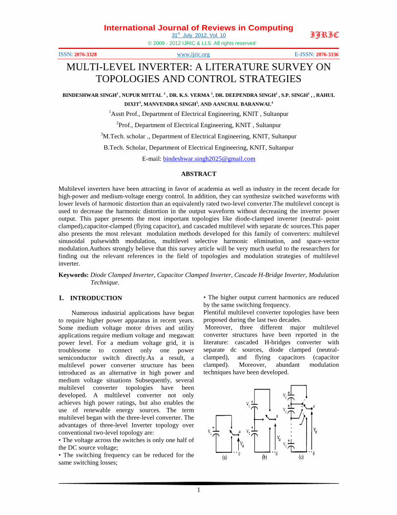
Figure.1: One Phase Leg Of An Inverter With (A) Two Levels, (B) Three Levels, And (C) N Levels.
Figure.1 shows a schematic diagram of one phase leg of inverters with different numbers of levels, for which the action of the power semiconductors is represented by an ideal switch with several positions. A two-level inverter generates an output voltage with two values (levels) with respect to the negative terminal of the capacitor [see Fig. 1(a)], while the three-level inverter generates three voltages, and so on.The most attractive features of multilevel inverters are as follows. 1. They can generate output voltages with
extremely low distortion and lower . 2. They draw input current with very low
distortion. 3. They generate smaller common-mode (CM)
voltage, thus reducing the stress in the motor bearings.In addition, using sophisticated modulation methods, CM voltages can be eliminated.
4. They can operate with a lower switching frequency.
A. DIODE-CLAMPED INVERTER
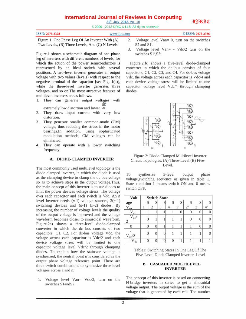
The most commonly used multilevel topology is the diode clamped inverter, in which the diode is used as the clamping device to clamp the dc bus voltage so as to achieve steps in the output voltage.Thus, the main concept of this inverter is to use diodes to limit the power devices voltage stress. The voltage over each capacitor and each switch is Vdc. An n level inverter needs (n-1) voltage sources, 2(n-1) switching devices and (n-1) (n-2) diodes. By increasing the number of voltage levels the quality of the output voltage is improved and the voltage waveform becomes closer to sinusoidal waveform. Figure.2a) shows a three-level diode-clamped converter in which the dc bus consists of two capacitors, C1, C2. For dc-bus voltage Vdc, the voltage across each capacitor is Vdc/2 and each device voltage stress will be limited to one capacitor voltage level Vdc/2 through clamping diodes. To explain how the staircase voltage is synthesized, the neutral point n is considered as the output phase voltage reference point. There are three switch combinations to synthesize three-level voltages across a and n.
1. Voltage level Van= Vdc/2, turn on the
switches S1andS2.
2. Voltage level Van= 0, turn on the switches S2 and S1′.
3. Voltage level Van= - Vdc/2 turn on the switches S1′,S2′.
Figure.2(b) shows a five-level diode-clamped
converter in which the dc bus consists of four capacitors, C1, C2, C3, and C4. For dc-bus voltage Vdc, the voltage across each capacitor is Vdc/4 and each device voltage stress will be limited to one capacitor voltage level Vdc/4 through clamping diodes.
Figure.2: Diode-Clamped Multilevel Inverter Circuit Topologies. (A) Three-Level.(B) Five-
Level.
To synthesize 5-level output phase voltage,switching sequence as given in table 1. State condition 1 means switch ON and 0 means switch OFF.
Volt
age Vao
Switch State S
1 S
2 S
3 S
4 S
1’ S
2’ S
3’ S
4’ Vdc 1 1 1 1 0 0 0 0 Vdc/
2 0 1 1 1 1 0 0 0
0 0 0 1 1 1 1 0 0 -
Vdc/2 0 0 0 1 1 1 1 0
-Vdc 0 0 0 0 1 1 1 1
Table1: Switching States In One Leg Of The Five-Level Diode Clamped Inverter -Level
B. CASCADED MULTILEVEL
INVERTER The concept of this inverter is based on connecting H-bridge inverters in series to get a sinusoidal voltage output. The output voltage is the sum of the voltage that is generated by each cell. The number
International Journal of Reviews in Computing 31st July 2012. Vol. 10
© 2009 - 2012 IJRIC & LLS. All rights reserved.
ISSN: 2076-3328 www.ijric.org E-ISSN: 2076-3336
3
IJRIC
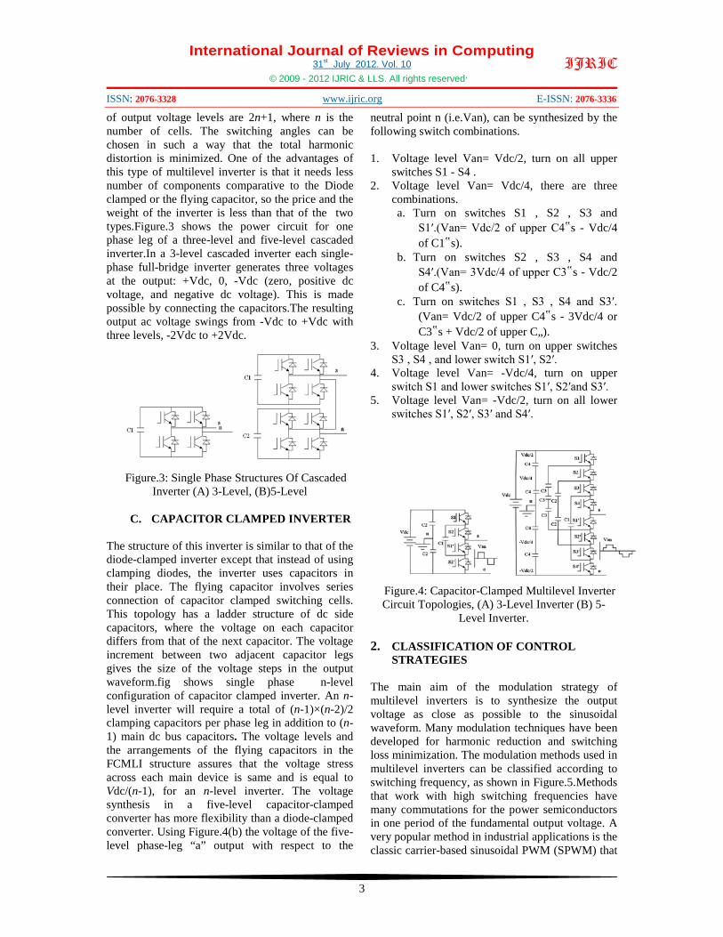
of output voltage levels are 2n+1, where n is the number of cells. The switching angles can be chosen in such a way that the total harmonic distortion is minimized. One of the advantages of this type of multilevel inverter is that it needs less number of components comparative to the Diode clamped or the flying capacitor, so the price and the weight of the inverter is less than that of the two types.Figure.3 shows the power circuit for one phase leg of a three-level and five-level cascaded inverter.In a 3-level cascaded inverter each single-phase full-bridge inverter generates three voltages at the output: +Vdc, 0, -Vdc (zero, positive dc voltage, and negative dc voltage). This is made possible by connecting the capacitors.The resulting output ac voltage swings from -Vdc to +Vdc with three levels, -2Vdc to +2Vdc.
Figure.3: Single Phase Structures Of Cascaded
Inverter (A) 3-Level, (B)5-Level
C. CAPACITOR CLAMPED INVERTER
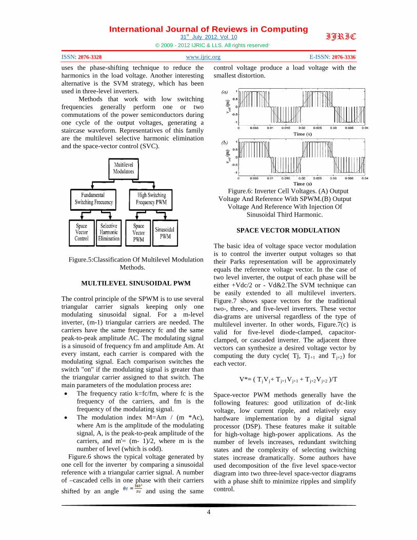
The structure of this inverter is similar to that of the diode-clamped inverter except that instead of using clamping diodes, the inverter uses capacitors in their place. The flying capacitor involves series connection of capacitor clamped switching cells. This topology has a ladder structure of dc side capacitors, where the voltage on each capacitor differs from that of the next capacitor. The voltage increment between two adjacent capacitor legs gives the size of the voltage steps in the output waveform.fig shows single phase n-level configuration of capacitor clamped inverter. An n-level inverter will require a total of (n-1)×(n-2)/2 clamping capacitors per phase leg in addition to (n-1) main dc bus capacitors. The voltage levels and the arrangements of the flying capacitors in the FCMLI structure assures that the voltage stress across each main device is same and is equal to Vdc/(n-1), for an n-level inverter. The voltage synthesis in a five-level capacitor-clamped converter has more flexibility than a diode-clamped converter. Using Figure.4(b) the voltage of the five-level phase-leg “a” output with respect to the
neutral point n (i.e.Van), can be synthesized by the following switch combinations.
1. Voltage level Van= Vdc/2, turn on all upper
switches S1 - S4 . 2. Voltage level Van= Vdc/4, there are three
combinations. a. Turn on switches S1 , S2 , S3 and
S1′.(Van= Vdc/2 of upper C4‟s - Vdc/4 of C1‟s).
b. Turn on switches S2 , S3 , S4 and S4′.(Van= 3Vdc/4 of upper C3‟s - Vdc/2 of C4‟s).
c. Turn on switches S1 , S3 , S4 and S3′. (Van= Vdc/2 of upper C4‟s - 3Vdc/4 or C3‟s + Vdc/2 of upper C„).
3. Voltage level Van= 0, turn on upper switches S3 , S4 , and lower switch S1′, S2′.
4. Voltage level Van= -Vdc/4, turn on upper switch S1 and lower switches S1′, S2′and S3′.
5. Voltage level Van= -Vdc/2, turn on all lower switches S1′, S2′, S3′ and S4′.
Figure.4: Capacitor-Clamped Multilevel Inverter Circuit Topologies, (A) 3-Level Inverter (B) 5-
Level Inverter.
2. CLASSIFICATION OF CONTROL STRATEGIES
The main aim of the modulation strategy of multilevel inverters is to synthesize the output voltage as close as possible to the sinusoidal waveform. Many modulation techniques have been developed for harmonic reduction and switching loss minimization. The modulation methods used in multilevel inverters can be classified according to switching frequency, as shown in Figure.5.Methods that work with high switching frequencies have many commutations for the power semiconductors in one period of the fundamental output voltage. A very popular method in industrial applications is the classic carrier-based sinusoidal PWM (SPWM) that
International Journal of Reviews in Computing 31st July 2012. Vol. 10
© 2009 - 2012 IJRIC & LLS. All rights reserved.
ISSN: 2076-3328 www.ijric.org E-ISSN: 2076-3336
4
IJRIC
uses the phase-shifting technique to reduce the harmonics in the load voltage. Another interesting alternative is the SVM strategy, which has been used in three-level inverters.
Methods that work with low switching frequencies generally perform one or two commutations of the power semiconductors during one cycle of the output voltages, generating a staircase waveform. Representatives of this family are the multilevel selective harmonic elimination and the space-vector control (SVC).
Figure.5:Classification Of Multilevel Modulation
Methods.
MULTILEVEL SINUSOIDAL PWM
The control principle of the SPWM is to use several triangular carrier signals keeping only one modulating sinusoidal signal. For a m-level inverter, (m-1) triangular carriers are needed. The carriers have the same frequency fc and the same peak-to-peak amplitude AC. The modulating signal is a sinusoid of frequency fm and amplitude Am. At every instant, each carrier is compared with the modulating signal. Each comparison switches the switch "on" if the modulating signal is greater than the triangular carrier assigned to that switch. The main parameters of the modulation process are: • The frequency ratio k=fc/fm, where fc is the
frequency of the carriers, and fm is the frequency of the modulating signal.
• The modulation index M=Am / (m *Ac), where Am is the amplitude of the modulating signal, A, is the peak-to-peak amplitude of the carriers, and m'= (m- 1)/2, where m is the number of level (which is odd).
Figure.6 shows the typical voltage generated by one cell for the inverter by comparing a sinusoidal reference with a triangular carrier signal. A number of –cascaded cells in one phase with their carriers shifted by an angle and using the same
control voltage produce a load voltage with the smallest distortion.
Figure.6: Inverter Cell Voltages. (A) Output
Voltage And Reference With SPWM.(B) Output Voltage And Reference With Injection Of
Sinusoidal Third Harmonic.
SPACE VECTOR MODULATION
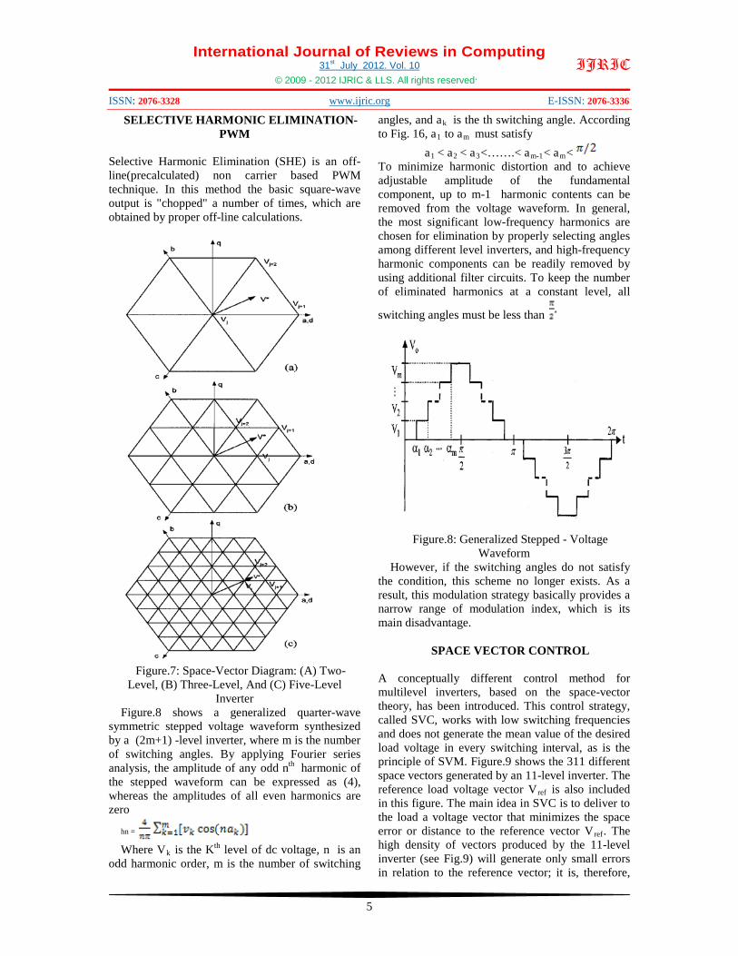
The basic idea of voltage space vector modulation is to control the inverter output voltages so that their Parks representation will be approximately equals the reference voltage vector. In the case of two level inverter, the output of each phase will be either +Vdc/2 or - Vd&2.The SVM technique can be easily extended to all multilevel inverters. Figure.7 shows space vectors for the traditional two-, three-, and five-level inverters. These vector dia-grams are universal regardless of the type of multilevel inverter. In other words, Figure.7(c) is valid for five-level diode-clamped, capacitor-clamped, or cascaded inverter. The adjacent three vectors can synthesize a desired voltage vector by computing the duty cycle( Tj, Tj+1 and Tj+2) for each vector.
V*= ( TjVj+ Tj+1Vj+1 + Tj+2Vj+2 )/T
Space-vector PWM methods generally have the following features: good utilization of dc-link voltage, low current ripple, and relatively easy hardware implementation by a digital signal processor (DSP). These features make it suitable for high-voltage high-power applications. As the number of levels increases, redundant switching states and the complexity of selecting switching states increase dramatically. Some authors have used decomposition of the five level space-vector diagram into two three-level space-vector diagrams with a phase shift to minimize ripples and simplify control.
International Journal of Reviews in Computing 31st July 2012. Vol. 10
© 2009 - 2012 IJRIC & LLS. All rights reserved.
ISSN: 2076-3328 www.ijric.org E-ISSN: 2076-3336
5
IJRIC
SELECTIVE HARMONIC ELIMINATION-PWM
Selective Harmonic Elimination (SHE) is an off-line(precalculated) non carrier based PWM technique. In this method the basic square-wave output is "chopped" a number of times, which are obtained by proper off-line calculations.
Figure.7: Space-Vector Diagram: (A) Two-
Level, (B) Three-Level, And (C) Five-Level Inverter
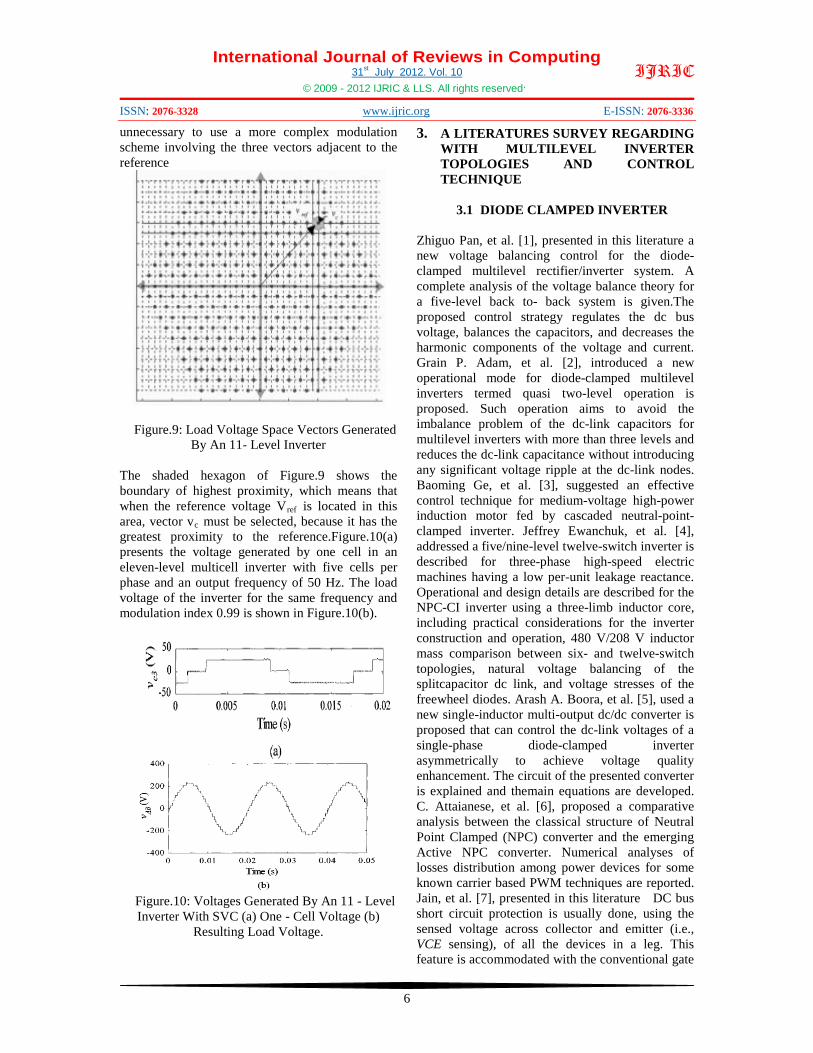
Figure.8 shows a generalized quarter-wave symmetric stepped voltage waveform synthesized by a (2m+1) -level inverter, where m is the number of switching angles. By applying Fourier series analysis, the amplitude of any odd nth harmonic of the stepped waveform can be expressed as (4), whereas the amplitudes of all even harmonics are zero
hn = Where Vk is the Kth level of dc voltage, n is an
odd harmonic order, m is the number of switching
angles, and ak is the th switching angle. According to Fig. 16, a1 to am must satisfy
a1 < a2 < a3<…….< am-1< am< To minimize harmonic distortion and to achieve adjustable amplitude of the fundamental component, up to m-1 harmonic contents can be removed from the voltage waveform. In general, the most significant low-frequency harmonics are chosen for elimination by properly selecting angles among different level inverters, and high-frequency harmonic components can be readily removed by using additional filter circuits. To keep the number of eliminated harmonics at a constant level, all
switching angles must be less than
Figure.8: Generalized Stepped - Voltage Waveform
However, if the switching angles do not satisfy the condition, this scheme no longer exists. As a result, this modulation strategy basically provides a narrow range of modulation index, which is its main disadvantage.
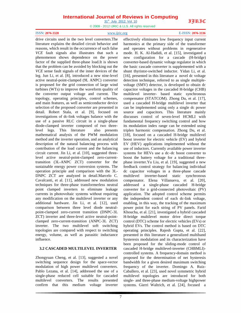
SPACE VECTOR CONTROL
A conceptually different control method for multilevel inverters, based on the space-vector theory, has been introduced. This control strategy, called SVC, works with low switching frequencies and does not generate the mean value of the desired load voltage in every switching interval, as is the principle of SVM. Figure.9 shows the 311 different space vectors generated by an 11-level inverter. The reference load voltage vector Vref is also included in this figure. The main idea in SVC is to deliver to the load a voltage vector that minimizes the space error or distance to the reference vector Vref. The high density of vectors produced by the 11-level inverter (see Fig.9) will generate only small errors in relation to the reference vector; it is, therefore,
International Journal of Reviews in Computing 31st July 2012. Vol. 10
© 2009 - 2012 IJRIC & LLS. All rights reserved.
ISSN: 2076-3328 www.ijric.org E-ISSN: 2076-3336
6
IJRIC
unnecessary to use a more complex modulation scheme involving the three vectors adjacent to the reference
Figure.9: Load Voltage Space Vectors Generated
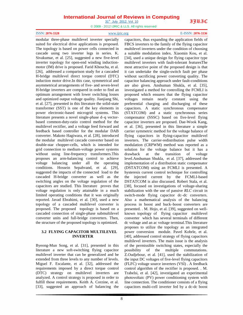
By An 11- Level Inverter The shaded hexagon of Figure.9 shows the boundary of highest proximity, which means that when the reference voltage Vref is located in this area, vector vc must be selected, because it has the greatest proximity to the reference.Figure.10(a) presents the voltage generated by one cell in an eleven-level multicell inverter with five cells per phase and an output frequency of 50 Hz. The load voltage of the inverter for the same frequency and modulation index 0.99 is shown in Figure.10(b).
Figure.10: Voltages Generated By An 11 - Level Inverter With SVC (a) One - Cell Voltage (b)
Resulting Load Voltage.
3. A LITERATURES SURVEY REGARDING WITH MULTILEVEL INVERTER TOPOLOGIES AND CONTROL TECHNIQUE
3.1 DIODE CLAMPED INVERTER
Zhiguo Pan, et al. [1], presented in this literature a new voltage balancing control for the diode-clamped multilevel rectifier/inverter system. A complete analysis of the voltage balance theory for a five-level back to- back system is given.The proposed control strategy regulates the dc bus voltage, balances the capacitors, and decreases the harmonic components of the voltage and current. Grain P. Adam, et al. [2], introduced a new operational mode for diode-clamped multilevel inverters termed quasi two-level operation is proposed. Such operation aims to avoid the imbalance problem of the dc-link capacitors for multilevel inverters with more than three levels and reduces the dc-link capacitance without introducing any significant voltage ripple at the dc-link nodes. Baoming Ge, et al. [3], suggested an effective control technique for medium-voltage high-power induction motor fed by cascaded neutral-point-clamped inverter. Jeffrey Ewanchuk, et al. [4], addressed a five/nine-level twelve-switch inverter is described for three-phase high-speed electric machines having a low per-unit leakage reactance. Operational and design details are described for the NPC-CI inverter using a three-limb inductor core, including practical considerations for the inverter construction and operation, 480 V/208 V inductor mass comparison between six- and twelve-switch topologies, natural voltage balancing of the splitcapacitor dc link, and voltage stresses of the freewheel diodes. Arash A. Boora, et al. [5], used a new single-inductor multi-output dc/dc converter is proposed that can control the dc-link voltages of a single-phase diode-clamped inverter asymmetrically to achieve voltage quality enhancement. The circuit of the presented converter is explained and themain equations are developed. C. Attaianese, et al. [6], proposed a comparative analysis between the classical structure of Neutral Point Clamped (NPC) converter and the emerging Active NPC converter. Numerical analyses of losses distribution among power devices for some known carrier based PWM techniques are reported. Jain, et al. [7], presented in this literature DC bus short circuit protection is usually done, using the sensed voltage across collector and emitter (i.e., VCE sensing), of all the devices in a leg. This feature is accommodated with the conventional gate
International Journal of Reviews in Computing 31st July 2012. Vol. 10
© 2009 - 2012 IJRIC & LLS. All rights reserved.
ISSN: 2076-3328 www.ijric.org E-ISSN: 2076-3336
7
IJRIC
drive circuits used in the two level converters.The literature explains the detailed circuit behavior and reasons, which result in the occurrence of such false VCE fault signals also illustrates that such a phenomenon shows dependence on the power factor of the supplied three-phase load.It is shown that the problem can be avoided by blocking out the VCE sense fault signals of the inner devices of the leg. Jun Li, et al. [8], introduced a new nine-level active neutral-point-clamped (9L ANPC) converter is proposed for the grid connection of large wind turbines (WTs) to improve the waveform quality of the converter output voltage and current. The topology, operating principles, control schemes, and main features, as well as semiconductor device selection of the proposed converter are presented in detail. Robert Stala, et al. [9], focused on investigations of dc-link voltages balance with the use of a passive RLC circuit in a single-phase diode-clamped inverter composed of two three-level legs. This literature also presents mathematical analysis of the PWM modulation method and the inverter operation, and an analytical description of the natural balancing process with contribution of the load current and the balancing circuit current. Jin Li, et al. [10], suggested three-level active neutral-point-clamped zero-current-transition (3L-ANPC ZCT) converter for the sustainable energy power conversion systems. The operation principle and comparison with the 3L-DNPC ZCT are analyzed in detail.Marcelo C. Cavalcanti, et al. [11], addressed new modulation techniques for three-phase transformerless neutral point clamped inverters to eliminate leakage currents in photovoltaic systems without requiring any modification on the multilevel inverter or any additional hardware. Jin Li, et al. [12], used comparison between three level diode neutral-point-clamped zero-current transition (DNPC-3L ZCT) inverter and three-level active neutral-point-clamped zero-current-transition (ANPC-3L ZCT) inverter. The two multilevel soft switching topologies are compared with respect to switching energy, volume, as well as parasitic inductance influence.
3.2 CASCADED MULTILEVEL INVERTER Zhongyuan Cheng, et al. [13], suggested a novel switching sequence design for the space-vector modulation of high power multilevel converters. Pablo Lezana, et al. [14], addressed the use of a single-phase reduced cell suitable for cascaded multilevel converters. The results presented confirm that this medium voltage inverter
effectively eliminates low frequency input current harmonics at the primary side of the transformer and operates without problems in regenerative mode. H. K. Al-Hadidi, et al. [15], investigated a new configuration for a cascade (H-bridge) converter-based dynamic voltage regulator in which the basic cascade converter is supplemented with a shunt thyristor-switched inductor. Yidan Li, et al. [16], presented in this literature a novel dc voltage detection technique, referred to as single multiple-voltage (SMV) detector, is developed to obtain dc capacitor voltages in the cascaded H-bridge (CHB) multilevel inverter- based static synchronous compensator (STATCOM). Zhong Du, et al. [17], used a cascaded H-bridge multilevel inverter that can be implemented using only a single dc power source and capacitors. This literature mainly discusses control of seven-level HCMLI with fundamental frequency switching control and how its modulation index range can be extended using triplen harmonic compensation. Zhong Du, et al. [18], focused on a cascaded H-bridge multilevel boost inverter for electric vehicle (EV) and hybrid EV (HEV) applications implemented without the use of inductors. Currently available power inverter systems for HEVs use a dc–dc boost converter to boost the battery voltage for a traditional three-phase inverter.Yu Liu, et al. [19], suggested a new feedback control strategy for balancing individual dc capacitor voltages in a three-phase cascade multilevel inverter-based static synchronous compensator. Elena Villanueva, et al. [20], addressed a single-phase cascaded H-bridge converter for a grid-connected photovoltaic (PV) application. The adopted control scheme permits the independent control of each dc-link voltage, enabling, in this way, the tracking of the maximum power point for each string of PV panels. Farid Khoucha, et al. [21], investigated a hybrid cascaded H-bridge multilevel motor drive direct torque control (DTC) scheme for electric vehicles (EVs) or hybrid EVs. The control method is based on DTC operating principles. Rajesh Gupta, et al. [22], presented in this literature a generalized multiband hysteresis modulation and its characterization have been proposed for the sliding-mode control of cascaded H-bridge multilevel-inverter (CHBMLI)-controlled systems. A frequency-domain method is proposed for the determination of net hysteresis bandwidth for a given desired maximum switching frequency of the inverter. Domingo A. Ruiz-Caballero, et al. [23], used novel symmetric hybrid multilevel topologies are introduced for both single- and three-phase medium-voltage highpower systems. Gierri Waltrich, et al. [24], focused a
International Journal of Reviews in Computing 31st July 2012. Vol. 10
© 2009 - 2012 IJRIC & LLS. All rights reserved.
ISSN: 2076-3328 www.ijric.org E-ISSN: 2076-3336
8
IJRIC
modular three-phase multilevel inverter specially suited for electrical drive applications is proposed. The topology is based on power cells connected in cascade using two inverter legs in series. K. Sivakumar, et al. [25], suggested a new five-level inverter topology for open-end winding induction-motor (IM) drive is proposed. Farid Khoucha, et al. [26], addressed a comparison study for a cascaded H-bridge multilevel direct torque control (DTC) induction motor drive.In this case, symmetrical and asymmetrical arrangements of five- and seven-level H-bridge inverters are compared in order to find an optimum arrangement with lower switching losses and optimized output voltage quality. Jianjiang Shi, et al. [27], presented in this literature the solid-state transformer (SST) is one of the key elements in power electronic-based microgrid systems. This literature presents a novel single-phase d–q vector-based common-duty-ratio control method for the multilevel rectifier, and a voltage feed forward and feedback based controller for the modular DAB converter. Makoto Hagiwara, et al. [28], introduced the modular multilevel cascade converter based on double-star chopper-cells, which is intended for grid connection to medium-voltage power systems without using line-frequency transformers.This proposes an arm-balancing control to achieve voltage balancing under all the operating conditions. Hossein Sepahvand, et al. [29], suggested the impacts of the connected load to the cascaded H-bridge converter as well as the switching angles on the voltage regulation of the capacitors are studied. This literature proves that voltage regulation is only attainable in a much limited operating conditions that it was originally reported. Javad Ebrahimi, et al. [30], used a new topology of a cascaded multilevel converter is proposed. The proposed topology is based on a cascaded connection of single-phase submultilevel converter units and full-bridge converters. Then, the structure of the proposed topology is optimized.
3.2 FLYING CAPACITOR MULTILEVEL INVERTER
Byeong-Mun Song, et al. [31], presented in this literature a new soft-switching flying capacitor multilevel inverter that can be generalized and be extended from three levels to any number of levels. Miguel F. Escalante, et al. [32], addressed the requirements imposed by a direct torque control (DTC) strategy on multilevel inverters are analyzed. A control strategy is proposed in order to fulfill those requirements. Keith A. Corzine, et al. [33], suggested an approach of balancing the
capacitors, thus expanding the application fields of FBCS inverters to the family of the flying capacitor multilevel inverters under the condition of choosing a suitable modulation index. Xiaomin Kou, et al. [34], used a unique design for flying capacitor type multilevel inverters with fault-tolerant featuresThe most attractive point of the proposed design is that it can undertake the single-switch fault per phase without sacrificing power converting quality. The capacitor balancing approach under fault-conditions are also given. Anshuman Shukla, et al. [35], investigated a method for controlling the FCMLI is proposed which ensures that the flying capacitor voltages remain nearly constant using the preferential charging and discharging of these capacitors. A static synchronous compensator (STATCOM) and a static synchronous series compensator (SSSC) based on five-level flying capacitor inverters are proposed. Dae-Wook Kang, et al. [36], presented in this literature a simple carrier symmetric method for the voltage balance of flying capacitors in flying-capacitor multilevel inverters. The carrier-redistribution pulse width modulation (CRPWM) method was reported as a solution for the voltage balance but it has a drawback at the transition of voltage level.Anshuman Shukla, et al. [37], addressed the implementation of a distribution static compensator (DSTATCOM) using an FCMLI is presented. A hysteresis current control technique for controlling the injected current by the FCMLI-based DSTATCOM is also discussed. Robert Stala, et al. [38], focused on investigations of voltage-sharing stabilization with the use of passive RLC circuit in switch-mode flying capacitor dc–dc converters. Also a mathematical analysis of the balancing process in boost and buck–boost converters are presented. . M. Hojo, et al. [39], suggested on well-known topology of flying capacitor multilevel converter which has several terminals of different dc voltage and an ac voltage terminal.This literature proposes to utilize the topology as an integrated power conversion module. Pavel Kobrle, et al. [40], addressed control strategy of flying capacitors multilevel inverters. The main issue is the analysis of the permissible switching states, especially the possibility of the multiple commutations. Z.Oudjebour, et al. [41], used the stabilization of the input DC voltages of five-level flying capacitors (FLFC) voltage source inverters (VSI) . A feedback control algorithm of the rectifier is proposed. . M. Trabelsi, et al. [42], investigated an experimental photovoltaic (PV) power conditioning system with line connection. The conditioner consists of a flying capacitors multi-cell inverter fed by a dc-dc boost
International Journal of Reviews in Computing 31st July 2012. Vol. 10
© 2009 - 2012 IJRIC & LLS. All rights reserved.
ISSN: 2076-3328 www.ijric.org E-ISSN: 2076-3336
9
IJRIC
converter. Mostafa Khazraei, et al. [43], presented in this literature two active capacitor voltage balancing schemes are proposed for single-phase (Hbridge) flying-capacitor multilevel converters. They are based on the circuit equations of flying capacitor converters. These methods are shown to be effective on capacitor voltage regulation in flying-capacitor multilevel converters. Anshuman Shukla, et al. [44], focused on the development of multilevel hysteresis current regulation strategies. Two such strategies have been discussed and some modifications in their control tasks have been proposed to achieve more reliable and improved performance.
3.4 SINUSOIDAL PWM Giuseppe Carrara, et al. [45], focused on generalization of the PWM “subharmonic” method to control single-phase or three phase multilevel voltage source inverters (VSI). N. A. Azli, et al. [46], addressed Implementation of a regular sampled PWM technique based on a single carrier multilevel modulation strategy on a multilevel inverter using a digital signal processor (DSP) is presented.G.P. Adam, et al. [47], discussed in detail the principle of operation, carrier-based pulse width modulation and a capacitors voltage balancing technique for three-level and five-level modular inverters. B. Shanthi, et al. [48], investigated on comparison of unipolar multicarrier Pulse Width Modulation (PWM) techniques for the Flying Capacitor Multi Level Inverter (FCMLI). This literature presents the different types of unipolar PWM strategies for the chosen inverter. Moncef Ben Smida, et al. [49], used an original multicarrier subharmonic pulsewidth modulation (PWM), called disposition band carrier and phase-shifted carrier PWM (DBC-PSC-PWM), method is developed to produce (n ×m + 1) output voltage levels and to improve the output voltage harmonic spectrum with a wide output frequency range. P.K. Chaturvedi, et al. [50], presented in this literature a carrier-based closed-loop control technique has been developed to reduce the switching losses based on insertion of ‘no switching’ zone within each half cycle of fundamental wave. Suroso, et al. [51], suggested a five-level pulse width modulation inverter configuration, including chopper circuits as DC current-power source circuits using small smoothing inductors, is verified through computer simulations and experimental tests. K.Ramani, et al. [52], designed a seven-level flying capacitor multilevel inverter by using sinusoidal pulse width modulation technique.Ilhami Colak, et al. [53],
addressed a modified Sinusoidal Pulse Width Modulation (SPWM) modulator with phase disposition that increases output waveform up to 7-level while reducing output harmonics. Wahidah Abd, et al. [54], presented in this literature pulse-width modulation (PWM) for single-phase five-level inverter via field-programmable gate array (FPGA).
3.5 SPACE VECTOR PWM Amit Kumar Gupta, et al. [55], presented in this literature a general SVPWM algorithm for multilevel inverters based on standard two-level SVPWM. The proposed method uses a simple mapping to achieve the SVPWM for a multilevel inverter. Ahmed M. Massoud, et al. [56], addressed two different space vector modulation (SVM) techniques viz., phase-shifted SVM and hybrid SVM, are used for multilevel inverter Pulse width-modulation generation. Amit Kumar Gupta, et al. [57], suggested a simple space vector pulsewidth modulation algorithm for a multilevel inverter for operation in the overmodulation range. The proposed scheme easily determines the location of the reference vector and calculates on-times. Óscar López, et al. [58], introduced a new space vector pulsewidth modulation algorithm for multilevel multiphase voltage source converters with switching state redundancy. The algorithm was implemented in a field-programmable gate array. Anish Gopinath, et al. [59], focused a view that the space vector locations of multilevel inverters possess a fractal structure, and the properties of fractal structure together with the simplicity of fractal arithmetic are exploited to generate the SVPWM. The proposed method does not use any lookup tables for sector identification. Aneesh Mohamed A. S., et al. [60], used a generalized method for the generation of space vector pulsewidth modulation (SVPWM) signals for multilevel inverters. A new technique is proposed in this literature, by which these two-level vectors are translated to the switching vectors of the multilevel inverter by adding the center of the subhexagon to the two-level vectors. Mohan M. Renge, et al. [61], presented in this literature an approach to reduce common-mode voltage (CMV) at the output of multilevel inverter using 3-D space-vector modulation (SVM). Behzad Vafakhah, et al. [62], addressed a new multilevel SVPWM technique with a five-segment switching sequence, where half-wave symmetrical PWM voltage waveforms are used to balance the inductor common-mode dc voltages and also to avoid all
International Journal of Reviews in Computing 31st July 2012. Vol. 10
© 2009 - 2012 IJRIC & LLS. All rights reserved.
ISSN: 2076-3328 www.ijric.org E-ISSN: 2076-3336
10
IJRIC
possible switching states with a high winding current ripple. Ahmed M. Massoud, et al. [63], suggested two discontinuous multilevel space vector modulation (SVM) techniques are implemented for DVR control and are shown to reduce inverter switching losses while maintaining virtually the same harmonic performance as the conventional multilevel SVM at a high number of levels. Gabriele Grandi, et al. [64], introduced two carrier-based modulation techniques for a dual two-level inverter with power sharing capability and proper multilevel voltage waveforms. Their main advantage is a simpler implementation compared to SVM. Xu She, et al. [65], focused a novel 3-D space modulation technique with voltage balancing capability is proposed for a cascaded seven-level rectifier stage of SST.
3.6 SHE-PWM Mohamed. S. A. Dahidah, et al. [66], suggested solutions to the switching transitions of a five-level SHE–PWM when both the quarter- and half-wave symmetry are abolished. Vladimir Blasko, et al. [67], used a novel and a systematic design approach for applying signal processing methods (like modified adaptive selective harmonic elimination algorithms) as an addition to conventional control. Alan J. Watson, et al. [68], presented in this literature a complete Harmonic Elimination Approach that is used to balance dc link voltages in a cascaded H-Bridge (CHB) multilevel rectifier. Mohamed S. A. Dahidah, et al. [69], addressed a generalized formulation for selective harmonic elimination pulse-width modulation (SHE-PWM) control suitable for high-voltage high-power cascaded multilevel voltage source converters (VSC) with both equal and nonequal dc sources used in constant frequency utility applications. Vassilios G. Agelidis, et al. [70], focused on a five-level symmetrically defined multilevel selective harmonic elimination pulsewidth modulation (MSHE–PWM) strategy is reported in this paper. It is mathematically expressed using Fourier-based equations on a line-to-neutral basis. R.N. Ray, et al. [71], introduced a method is presented to compute the switching angles for selected harmonic elimination (SHE) in a multilevel inverter using the particle swarm optimisation technique. Fanghua Zhang, et al. [72], suggested a selective harmonic elimination (SHE) control strategy on a three-phase four-leg inverter is reported. Wanmin Fei, et al. [73], used a generalized formulation of quarter-wave symmetrical selective harmonic elimination (SHE) problems according to the rising and falling
edges of the pulsewidth modulation (PWM) waveforms for multilevel inverters. The SHE-PWM equations that can eliminate harmonics from 5th to 35th with modulation index M varying from 0 to 1.15 are formulated, and solutions are presented. Wanmin Fei, et al. [74], presented in this literature a novel generalized formulation of half-cycle symmetry SHE-PWM problems for multilevel inverters. A method to obtain initial values for the SHE-PWM equations according to the reference modulation index M and the initial phase angle of output fundamental voltage is proposed and investigated thoroughly. H. Taghizadeh, et al. [75], addressed the elimination of harmonics in a cascade multilevel inverter by considering the non equality of separated dc sources by using particle swarm optimization is presented. Mohamed S. A. Dahidah, et al. [76], focused on a new formulation of selective harmonic elimination pulse width modulation (SHE-PWM) technique suitable for cascaded multilevel inverters with optimized DC voltage levels. Sridhar R. Pulikanti, et al. [77], introduced a neutral point voltage control strategy for the three-level active neutral point clamped (ANPC) converter using selective harmonic elimination pulsewidth modulation (SHE-PWM). Sridhar R. Pulikanti, et al. [78], presented in this literature a control strategy is proposed to regulate the voltage across the FCs at their respective reference voltage levels by swapping the switching patterns of the switches based on the polarity of the output current, the polarity of the FC voltage, and the polarity of the fundamental line-to-neutral voltage under selective harmonic elimination pulsewidth modulation.
3.7 SPACE VECTOR CONTROL José Rodríguez, et al. [79], addressed a switching strategy for multilevel cascade inverters, based on the space-vector theory. The proposed switching strategy generates a voltage vector with very low harmonic distortion and reduced switching frequency. Anandarup Das, et al. [80], used a new PWM technique for induction motor drives involving six concentric dodecagonal space vector structures is proposed. Liliang Gao, et al. [81], suggested a novel space vector modulation (SVM) technique for a three-level five-phase inverter is described based on an optimized five vectors concept. José Rodríguez, et al. [82], introduced a switching strategy for multilevel cascade inverters, based on the space-vector theory. The proposed high-performance strategy generates a voltage
International Journal of Reviews in Computing 31st July 2012. Vol. 10
© 2009 - 2012 IJRIC & LLS. All rights reserved.
ISSN: 2076-3328 www.ijric.org E-ISSN: 2076-3336
11
IJRIC
vector across the load with minimum error with respect to the sinusoidal reference.
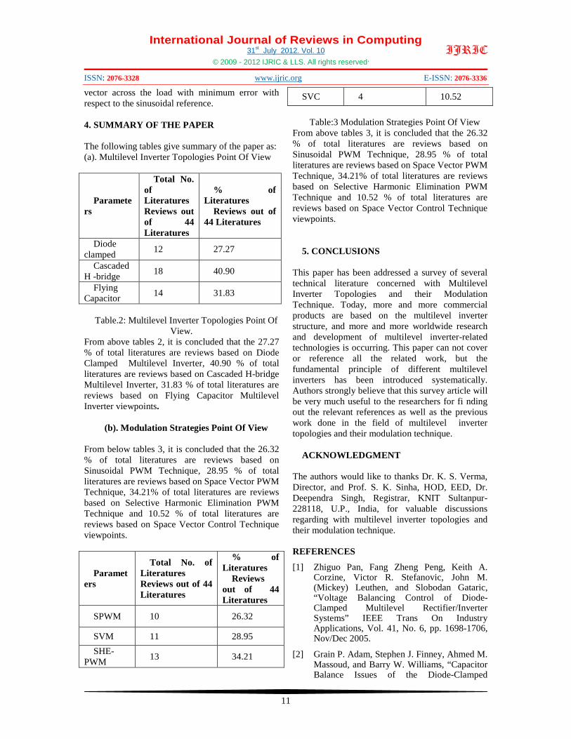
4. SUMMARY OF THE PAPER The following tables give summary of the paper as: (a). Multilevel Inverter Topologies Point Of View
Parameters
Total No. of Literatures Reviews out of 44 Literatures
% of Literatures
Reviews out of 44 Literatures
Diode clamped 12 27.27
Cascaded H -bridge 18 40.90
Flying Capacitor 14 31.83
Table.2: Multilevel Inverter Topologies Point Of
View. From above tables 2, it is concluded that the 27.27 % of total literatures are reviews based on Diode Clamped Multilevel Inverter, 40.90 % of total literatures are reviews based on Cascaded H-bridge Multilevel Inverter, 31.83 % of total literatures are reviews based on Flying Capacitor Multilevel Inverter viewpoints.
(b). Modulation Strategies Point Of View From below tables 3, it is concluded that the 26.32 % of total literatures are reviews based on Sinusoidal PWM Technique, 28.95 % of total literatures are reviews based on Space Vector PWM Technique, 34.21% of total literatures are reviews based on Selective Harmonic Elimination PWM Technique and 10.52 % of total literatures are reviews based on Space Vector Control Technique viewpoints.
Parameters
Total No. of Literatures Reviews out of 44 Literatures
% of Literatures
Reviews out of 44 Literatures
SPWM 10 26.32
SVM 11 28.95 SHE-
PWM 13 34.21
SVC 4 10.52
Table:3 Modulation Strategies Point Of View From above tables 3, it is concluded that the 26.32 % of total literatures are reviews based on Sinusoidal PWM Technique, 28.95 % of total literatures are reviews based on Space Vector PWM Technique, 34.21% of total literatures are reviews based on Selective Harmonic Elimination PWM Technique and 10.52 % of total literatures are reviews based on Space Vector Control Technique viewpoints.
5. CONCLUSIONS This paper has been addressed a survey of several technical literature concerned with Multilevel Inverter Topologies and their Modulation Technique. Today, more and more commercial products are based on the multilevel inverter structure, and more and more worldwide research and development of multilevel inverter-related technologies is occurring. This paper can not cover or reference all the related work, but the fundamental principle of different multilevel inverters has been introduced systematically. Authors strongly believe that this survey article will be very much useful to the researchers for fi nding out the relevant references as well as the previous work done in the field of multilevel inverter topologies and their modulation technique.
ACKNOWLEDGMENT The authors would like to thanks Dr. K. S. Verma, Director, and Prof. S. K. Sinha, HOD, EED, Dr. Deependra Singh, Registrar, KNIT Sultanpur-228118, U.P., India, for valuable discussions regarding with multilevel inverter topologies and their modulation technique. REFERENCES
[1] Zhiguo Pan, Fang Zheng Peng, Keith A. Corzine, Victor R. Stefanovic, John M. (Mickey) Leuthen, and Slobodan Gataric, “Voltage Balancing Control of Diode-Clamped Multilevel Rectifier/Inverter Systems” IEEE Trans On Industry Applications, Vol. 41, No. 6, pp. 1698-1706, Nov/Dec 2005.
[2] Grain P. Adam, Stephen J. Finney, Ahmed M. Massoud, and Barry W. Williams, “Capacitor Balance Issues of the Diode-Clamped
International Journal of Reviews in Computing 31st July 2012. Vol. 10
© 2009 - 2012 IJRIC & LLS. All rights reserved.
ISSN: 2076-3328 www.ijric.org E-ISSN: 2076-3336
12
IJRIC
Multilevel Inverter Operated in a Quasi Two-State Mode” IEEE Trans On Industrial Electronics, Vol. 55, NO. 8, pp. 3088- 3099 , Aug 2008.
[3] Baoming Ge, Fang Zheng Peng, Aníbal T. de Almeida, and Haitham Abu-Rub, “An Effective Control Technique for Medium-Voltage High-Power Induction Motor Fed by Cascaded Neutral-Point-Clamped Inverter”, IEEE Trans On Industrial Electronics, Vol. 57, No. 8, pp. 2659-2668, Aug 2010.
[4] Jeffrey Ewanchuk, John Salmon, and Behzad Vafakhah, “A Five-/Nine-Level Twelve-SwitchNeutral-Point-Clamped Inverter for High-Speed Electric Drives”, IEEE Trans On Industry Applications, Vol. 47, No. 5, pp. 2145-2153, Sept/Oct 2011.
[5] Arash A. Boora, Alireza Nami, Firuz Zare, Arindam Ghosh, and Frede Blaabjerg, “Voltage-Sharing Converter to Supply Single-Phase Asymmetrical Four-Level Diode-Clamped Inverter With High Power Factor Loads”, IEEE Trans On Power Electronics, Vol. 25, No. 10, Pp. 2507-2520, Oct 2010.
[6] C. Attaianese, M. Di Monaco, and G. Tomasso, “Three-Phase Three-Level Active NPC Converters for High Power System”, International Symposium on Power Electronics, Electrical Drives, Automation and Motion, pp. 204-209, Speedam 2010.
[7] Amit Kumar Jain, and V. T. Ranganathan, “VCE Sensing for IGBT Protection in NPC Three Level Converters—Causes For Spurious Trippings and Their Elimination”, IEEE Trans On Power Electronics, Vol. 26, No. 1, pp. 298-307, Jan 2011.
[8] Jun Li, Subhashish Bhattacharya, and Alex Q. Huang, “A New Nine-Level Active NPC (ANPC) Converter for Grid Connection of Large Wind Turbines for Distributed Generation”, IEEE Trans On Power Electronics, Vol. 26, No. 3, pp. 961-972, March 2011.
[9] Robert Stala, “Application of Balancing Circuit for DC-Link Voltages Balance in a Single-Phase Diode-Clamped Inverter With Two Three-Level Legs”, IEEE Trans On Industrial Electronics, Vol. 58, No. 9, pp. 4185-4195, Sept 2011.
[10] Jin Li, Jinjun Liu, Dushan Boroyevich, Paolo Mattavelli, and Yaosuo Xue, “Three-level Active Neutral-Point-Clamped Zero-Current-Transition Converter for Sustainable Energy
Systems”, IEEE Trans. On Power Electronics, Vol. 26, No. 12, pp. 3680-3693, Dec 2011.
[11] Marcelo C. Cavalcanti, Alexandre M. Farias, Kleber C. Oliveira, Francisco A. S. Neves, and João L. Afonso, “Eliminating Leakage Currents in Neutral Point Clamped Inverters for Photovoltaic Systems”, IEEE Trans. On Industrial Electronics, Vol. 59, No. 1, pp. 435- 443, Jan 2012.
[12] Jin Li, Jinjun Liu, Dushan Boroyevich, Paolo Mattavelli, and Yaosuo Xue, “Comparative Analysis of Three-Level Diode Neural-Point-Clamped and Active Neural-Point-Clamped Zero-Current-Transition Inverters”, 8th International Conference on Power Electronics, pp. 2290-2295, May 30-June 3, 2011.
[13] Zhongyuan Cheng, and Bin Wu, “A Novel Switching Sequence Design for Five-Level NPC/H-Bridge Inverters With Improved Output Voltage Spectrum and Minimized Device Switching Frequency”, IEEE Trans. On Power Electronics, Vol. 22, No. 6, pp.2138-2145, Nov 2007.
[14] Pablo Lezana, José Rodríguez, and Diego A. Oyarzún, “Cascaded Multilevel Inverter With Regeneration Capability and Reduced Number of Switches”, IEEE Trans. On Industrial Electronics, Vol. 55, No. 3, pp. 1059-1066, March 2008.
[15] H. K. Al-Hadidi, A. M. Gole, and David A. Jacobson, “A Novel Configuration for a Cascade Inverter-Based Dynamic Voltage Restorer With Reduced Energy Storage Requirements”, IEEE Trans. On Power Delivery, Vol. 23, No. 2, pp. 881-888, April 2008.
[16] Yidan Li and Bin Wu, “A Novel DC Voltage Detection Technique in the CHB Inverter-Based STATCOM”, IEEE Trans. On Power Delivery, Vol. 23, No. 3, pp. 1613-1619, July 2008.
[17] Zhong Du, Leon M. Tolbert, Burak Ozpineci, and John N. Chiasson, “Fundamental Frequency Switching Strategies of a Seven-Level Hybrid Cascaded H-Bridge Multilevel Inverter”, IEEE Trans. On Power Electronics, Vol. 24, No. 1, pp. 25- 33, Jan 2009.
[18] Zhong Du, Burak Ozpineci, Leon M. Tolbert, and John N. Chiasson, “DC–AC Cascaded H-Bridge Multilevel Boost Inverter With No Inductors for Electric/Hybrid Electric Vehicle Applications”, IEEE Trans.
International Journal of Reviews in Computing 31st July 2012. Vol. 10
© 2009 - 2012 IJRIC & LLS. All rights reserved.
ISSN: 2076-3328 www.ijric.org E-ISSN: 2076-3336
13
IJRIC
On Industry Applications, Vol. 45, No. 3, Pp. 963-970, May/June 2009.
[19] Yu Liu, Alex Q. Huang, Wenchao Song, Subhashish Bhattacharya, and Guojun Tan, “Small-Signal Model-Based Control Strategy for Balancing Individual DC Capacitor Voltages in Cascade Multilevel Inverter-Based STATCOM”, IEEE Trans. On Industrial Electronics, Vol. 56, No. 6, pp. 2259-2269, June 2009.
[20] Elena Villanueva, Pablo Correa, José Rodríguez, and Mario Pacas, “Control of a Single-Phase Cascaded H-Bridge Multilevel Inverter for Grid-Connected Photovoltaic Systems”, IEEE Trans. On Industrial Electronics, Vol. 56, No. 11, pp. 4399-4406, Nov. 2009.
[21] Farid Khoucha, Soumia Mouna Lagoun, Khoudir Marouani, Abdelaziz Kheloui, and Mohamed El Hachemi Benbouzid, “Hybrid Cascaded H-Bridge Multilevel-Inverter Induction-Motor-Drive Direct Torque Control for Automotive Applications”, IEEE Trans. On Industrial Electronics, Vol. 57, No. 3, pp. 892-899, March 2010.
[22] Rajesh Gupta, Arindam Ghosh, and Avinash Joshi, “Multiband Hysteresis Modulation and Switching Characterization for Sliding-Mode-Controlled Cascaded Multilevel Inverter”, IEEE Trans. On Industrial Electronics, Vol. 57, No. 7, pp. 2344-2353, July 2010.
[23] Domingo A. Ruiz-Caballero, Reynaldo M. Ramos-Astudillo, Samir Ahmad Mussa, and Marcelo Lobo Heldwein, “Symmetrical Hybrid Multilevel DC–AC Converters With Reduced Number of Insulated DC Supplies”, IEEE Trans. On Industrial Electronics, Vol. 57, No. 7, pp. 2307-2314, July 2010.
[24] Gierri Waltrich, and Ivo Barbi, “Three-Phase Cascaded Multilevel Inverter Using Power Cells With Two Inverter Legs in Series”, IEEE Trans. On Industrial Electronics, Vol. 57, No. 8, pp. 2605-2612, Aug 2010.
[25] K. Sivakumar, Anandarup Das, Rijil Ramchand, Chintan Patel, and K. Gopakumar, “A Hybrid Multilevel Inverter Topology for an Open-End Winding Induction-Motor Drive Using Two-Level Inverters in Series With a Capacitor-Fed H-Bridge Cell”, IEEE Trans. On Industrial Electronics, Vol. 57, No. 11, Pp. 3707-3714, Nov. 2010.
[26] Farid Khoucha, Mouna Soumia Lagoun, Abdelaziz Kheloui, and Mohamed El Hachemi Benbouzid, “A Comparison of
Symmetrical and Asymmetrical Three-Phase H-Bridge Multilevel Inverter for DTC Induction Motor Drives”, IEEE Trans On Energy Conversion, Vol. 26, No. 1, pp. 64-72, March 2011.
[27] Jianjiang Shi, Wei Gou, Hao Yuan, Tiefu Zhao, and Alex Q. Huang, “Research on Voltage and Power Balance Control for Cascaded Modular Solid-State Transformer”, IEEE Trans. On Power Electronics, Vol. 26, No. 4, pp. 1154-1166, April 2011.
[28] Makoto Hagiwara, Ryo Maeda, and Hirofumi Akagi, “Control and Analysis of the Modular Multilevel Cascade Converter Based on Double-Star Chopper-Cells (MMCC-DSCC)”, IEEE Trans. On Power Electronics, Vol. 26, No. 6, pp.1649-1658, June 2011.
[29] Hossein Sepahvand, Jingsheng Liao, and Mehdi Ferdowsi, “Investigation on Capacitor Voltage Regulation in Cascaded H-Bridge Multilevel Converters With Fundamental Frequency Switching”, IEEE Trans. On Industrial Electronics, Vol. 58, No. 11, pp. 5102-5111, Nov. 2011.
[30] Javad Ebrahimi, Ebrahim Babaei, and Goverg B. Gharehpetian, “A New Topology of Cascaded Multilevel Converters With Reduced Number of Components for High-Voltage Applications”, IEEE Trans. On Power Electronics, Vol. 26, No. 11,pp. 3109-3118, Nov. 2011.
[31] Byeong-Mun Song, Junhyung Kim, Jih-Sheng Lai, Ki-Chul Seong, Hae-Jong Kim, and Sun-Soon Park, “A Multilevel Soft-Switching Inverter with Inductor Coupling”, IEEE Trans. On Industry Applications, Vol. 37, No. 2, pp. 628-636, March/April 2001.
[32] Miguel F. Escalante, Jean-Claude Vannier, and Amir Arzandé, “Flying Capacitor Multilevel Inverters and DTC Motor Drive Applications”, IEEE Trans. On Industrial Electronics, Vol. 49, No. 4, pp.809-815, Aug 2002.
[33] Keith A. Corzine, and Xiaomin Kou, “Capacitor Voltage Balancing in Full Binary Combination Schema Flying Capacitor Multilevel Inverters”, IEEE Power Electronic Letters, Vol. 1, No. 1, pp. 2-5, March 2003.
[34] Xiaomin Kou, Keith A. Corzine, and Yakov L. Familiant, “A Unique Fault-Tolerant Design for Flying Capacitor Multilevel Inverter”, IEEE Trans. On Power Electronics, Vol. 19, No. 4, pp. 979-987, July 2004.
International Journal of Reviews in Computing 31st July 2012. Vol. 10
© 2009 - 2012 IJRIC & LLS. All rights reserved.
ISSN: 2076-3328 www.ijric.org E-ISSN: 2076-3336
14
IJRIC
[35] Anshuman Shukla, Arindam Ghosh, and Avinash Joshi, “Static Shunt and Series Compensations of an SMIB System Using Flying Capacitor Multilevel Inverter”, IEEE Trans. On Power Delivery, Vol. 20, No. 4, pp. 2613-2622, Oct 2005.
[36] Dae-Wook Kang, Byoung-Kuk Lee,Jae-Hyun Jeon, Tae-Jin Kim,and Dong-Seok Hyun, “A Symmetric Carrier Technique of CRPWM for Voltage Balance Method of Flying-Capacitor Multilevel Inverter”, IEEE Trans. On Industrial Electronics, Vol. 52, No. 3,pp. 879-888, June 2005.
[37] Anshuman Shukla, Arindam Ghosh, and Avinash Joshi, “Hysteresis Current Control Operation of Flying Capacitor Multilevel Inverter and Its Application in Shunt Compensation of Distribution Systems”, IEEE Trans. On Power Delivery, Vol. 22, No. 1, pp. 396-405, Jan 2007.
[38] Robert Stala, “The Switch-Mode Flying-Capacitor DC–DC Converters With Improved Natural Balancing”, IEEE Trans. On Industrial Electronics, Vol. 57, No. 4, pp. 1369-1382, April 2010.
[39] M. Hojo, and K. Minato, “Integrated Power Conversion for DC Power System by Flying Capacitor Multi-Level Converter”, The 2010 International Power Electronics Conference, pp. 337-342, 2010.
[40] Pavel Kobrle, Jiří Pavelka, “Analysis of Permissible State of Flying Capacitors Multilevel Inverter Switch”, 14th International Power Electronics and Motion Control Conference, pp. T3-42 – T3-45, oct. 2010.
[41] Z.Oudjebour and E.M.Berkouk, M.O.Mahmoudi, “Modelling, Control and Feedback Control of the Multilevel Flying Capacitors Rectifier. Application to Double Star Induction Machine”, IEEE International Energy Conference, pp. 507-512, 2010.
[42] M. Trabelsi, and L. Ben-Brahim, “Development Of A Grid Connected Photovoltaic Power Conditioning System Based On Flying Capacitors Inverter”, 8th International Multi-Conference on Systems, Signals & Devices, pp. 1-6, May 2011.
[43] Mostafa Khazraei, Hossein Sepahvand, Keith A. Corzine, and Mehdi Ferdowsi, “Active Capacitor Voltage Balancing in Single-Phase Flying-Capacitor Multilevel Power Converters”, IEEE Trans. On Industrial
Electronics, Vol. 59, No. 2, pp. 769-778, Feb. 2012.
[44] Anshuman Shukla, Arindam Ghosh, and Avinash Joshi, “Improved Multilevel Hysteresis Current Regulation and Capacitor Voltage Balancing Schemes for Flying Capacitor Multilevel Inverter”, IEEE Trans. On Power Electronics, Vol. 23, No. 2, pp. 518-529, March 2008.
[45] Giuseppe Carrara, Simone Gardella, Mario Marchesoni, Raffaele Salutari, and Giuseppe Sciutto, “A New Multilevel PWM Method: A Theoretical Analysis”, IEEE Trans. On Power Electronics, Vol. 7, No. 3, pp. 497-505, July 1992.
[46] N. A. Azli and M. S, Sakar, “A DSP-based Regular Sampled Pulsewidth Modulation (PWM) Technique for a Multilevel Inverter”, lmtematlonal Conference on Power System Technology, pp. 1613-1618,Nov. 2004.
[47] G.P. Adam, O. Anaya-Lara, G.M. Burt, D. Telford, B.W. Williams, and J.R. McDonald, “Modular multilevel inverter: pulse width modulation and capacitor balancing technique”, Published in IET Power Electronics, Vol. 3, Iss. 5, pp. 702-715, 2010.
[48] B. Shanthi and S.P. Natarajan, “Comparative Study on Unipolar Multicarrier PWM Strategies for Five Level Flying Capacitor Inverter”, International Conference On “Control, Automation, Communication And Energy Conservation, pp. 1-7, Jun 2009.
[49] Moncef Ben Smida and Faouzi Ben Ammar, “Modeling and DBC-PSC-PWM Control of a Three-Phase Flying-Capacitor Stacked Multilevel Voltage Source Inverter”, IEEE Trans. On Industrial Electronics, Vol. 57, No. 7, pp. 2231-2239, July 2010.
[50] P.K. Chaturvedi, S. Jain, P. Agarwal, “Reduced switching loss pulse width modulation technique for three-level diode clamped inverter”, Published in IET Power Electronics, Vol. 4, Iss. 4, pp. 393–399, 2011.
[51] Suroso, and T. Noguchi, “Common-emitter topology of multilevel current-source pulse width modulation inverter with chopper-based DC current sources”, Published in IET Power Electronics, Vol. 4, Iss. 7, pp. 759–766, 2010.
[52] K.Ramani and Dr.A.Krishnan, “High Performance of Sinusoidal Pulse Width Modulation Based Flying Capacitor Multilevel Inverter fed induction Motor
International Journal of Reviews in Computing 31st July 2012. Vol. 10
© 2009 - 2012 IJRIC & LLS. All rights reserved.
ISSN: 2076-3328 www.ijric.org E-ISSN: 2076-3336
15
IJRIC
Drive”, International Journal of Computer Applications (0975 - 8887) Volume 1 – No. 24, pp. 98-103, 2010.
[53] Ilhami Colak, Ramazan Bayindir, Ersan Kabalci, “Design and Analysis of a 7-Level Cascaded Multilevel Inverter with Dual SDCSs”, International Symposium on Power Electronics, Electrical Drives, Automation and Motion, pp.180-185, 2010.
[54] Wahidah Abd. Halim and Nasrudin Abd. Rahim, “FPGA-Based Pulse-Width Modulation Control For Single-Phase Multilevel Inverter”, IEEE First Conference on Clean Energy and Technology, CET, pp.57-62, 2011.
[55] Amit Kumar Gupta, and Ashwin M. Khambadkone, “A Space Vector PWM Scheme for Multilevel Inverters Based on Two-Level Space Vector PWM”, IEEE Trans. On Industrial Electronics, Vol. 53, No. 5, pp. 1631-1639, Oct 2006.
[56] Ahmed M. Massoud, Stephen J. Finney, Andrew J. Cruden, and Barry W. Williams, “Three-Phase, Three-Wire, Five-Level Cascaded Shunt Active Filter for Power Conditioning, Using Two Different Space Vector Modulation Techniques”, IEEE Trans. On Power Delivery, Vol. 22, No. 4, pp. 2349-2361, Oct. 2007.
[57] Amit Kumar Gupta, and Ashwin M. Khambadkone, “A General Space Vector PWM Algorithm for Multilevel Inverters, Including Operation in Over modulation Range”, IEEE Trans. On Power Electronics, Vol. 22, No. 2, pp. 517-526, March 2007.
[58] Óscar López, Jacobo Álvarez, Jesús Doval-Gandoy, And Francisco D. Freijedo, “Multilevel Multiphase Space Vector PWM Algorithm With Switching State Redundancy”, IEEE Trans. On Industrial Electronics, Vol. 56, No. 3, pp. 792- 804, March 2009.
[59] Anish Gopinath, Aneesh Mohamed A. S., and M. R. Baiju, “Fractal Based Space Vector PWM for Multilevel Inverters—A Novel Approach”, IEEE Trans. On Industrial Electronics, Vol. 56, No. 4, pp. 1230-1237, April 2009.
[60] Aneesh Mohamed A. S., Anish Gopinath, and M. R. Baiju, “A Simple Space Vector PWM Generation Scheme for Any General n-Level Inverter”, IEEE Trans. On Industrial Electronics, Vol. 56, No. 5, pp. 1649-1656, May 2009.
[61] Mohan M. Renge and Hiralal M. Suryawanshi, “Three-Dimensional Space-Vector Modulation to Reduce Common-Mode Voltage for Multilevel Inverter”, IEEE Trans. On Industrial Electronics, Vol. 57, No. 7, pp. 2324-2331, July 2010.
[62] Behzad Vafakhah, John Salmon, and Andrew M. Knight, “A New Space-Vector PWM With Optimal Switching Selection for Multilevel Coupled Inductor Inverters”, IEEE Trans. On Industrial Electronics, Vol. 57, No. 7, pp. 2354-2364, July 2010.
[63] Ahmed M. Massoud, Shehab Ahmed, Prasad N. Enjeti, and Barry W. Williams, “Evaluation of a Multilevel Cascaded-Type Dynamic Voltage Restorer Employing Discontinuous Space Vector Modulation”, IEEE Trans. On Industrial Electronics, Vol. 57, No. 7, pp. 2398- 2410 July 2010.
[64] Gabriele Grandi, and Darko Ostojic, “Carrier-Based Discontinuous Modulation for Dual Three-Phase Two-Level Inverters”, International Symposium on Power Electronics, Electrical Drives, Automation and Motion, pp. 839-844, Speedam 2010.
[65] Xu She, Alex Q. Huang, and Gangyao Wang, “3-D Space Modulation With Voltage Balancing Capability for a Cascaded Seven-Level Converter in a Solid-State Transformer”, IEEE TRANS. On Power Electronics, Vol. 26, No. 12, pp. 3778-3789, Dec. 2011.
[66] Mohamed. S. A. Dahidah, Vassilios G. Agelidis, and Machavaram V. Rao, “On Abolishing Symmetry Requirements in the Formulation of a Five-Level Selective Harmonic Elimination Pulse-Width Modulation Technique”, IEEE Trans. On Power Electronics, Vol. 21, No. 6, pp. 1833-1837, Nov. 2006.
[67] Vladimir Blasko, “A Novel Method for Selective Harmonic Elimination in Power Electronic Equipment”, IEEE Trans. On Power Electronics, Vol. 22, No. 1, pp. 223-228, Jan. 2007.
[68] Alan J. Watson, Patrick W. Wheeler, and Jon C. Clare, “A Complete Harmonic Elimination Approach to DC Link Voltage Balancing for a Cascaded Multilevel Rectifier”, IEEE Trans. On Industrial Electronics, Vol. 54, No. 6, pp. 2946-2953, Dec. 2007.
[69] Mohamed S. A. Dahidah, and Vassilios G. Agelidis, “Selective Harmonic Elimination PWM Control for Cascaded Multilevel
International Journal of Reviews in Computing 31st July 2012. Vol. 10
© 2009 - 2012 IJRIC & LLS. All rights reserved.
ISSN: 2076-3328 www.ijric.org E-ISSN: 2076-3336
16
IJRIC
Voltage Source Converters: A Generalized Formula”, IEEE Trans. On Power Electronics, Vol. 23, No. 4, pp. 1620-1630, July 2008.
[70] Vassilios G. Agelidis, Anastasios I. Balouktsis, and Mohamed S. A. Dahidah, “A Five-Level Symmetrically Defined Selective Harmonic Elimination PWM Strategy: Analysis and Experimental Validation”, IEEE Trans. On Power Electronics, Vol. 23, No. 1, pp. 19-26, Jan. 2008.
[71] R.N. Ray, D. Chatterjee, and S.K. Goswami, “Harmonics elimination in a multilevel inverter using the particle swarm optimisation technique”, Published in IET Power Electronics, Vol. 2, Iss. 6, pp. 646–652, 2008.
[72] Fanghua Zhang, and Yangguang Yan, “Selective Harmonic Elimination PWM Control Scheme on a Three-Phase Four-Leg Voltage Source Inverter”, IEEE Trans. On Power Electronics, Vol. 24, No.7, pp.1682-1689, July 2009.
[73] Wanmin Fei, Xinbo Ruan, and Bin Wu, “A Generalized Formulation of Quarter-Wave Symmetry SHE-PWM Problems for Multilevel Inverters”, IEEE Trans. On Power Electronics, Vol. 24, No. 7, pp. 1758-1766, July 2009.
[74] Wanmin Fei, Xiaoli Du, and Bin Wu, “A Generalized Half-Wave Symmetry SHE-PWM Formulation for Multilevel Voltage Inverters”, IEEE Trans. On Industrial Electronics, Vol. 57, No. 9,pp. 3030-3038, Sept. 2010.
[75] H. Taghizadeh and M. Tarafdar Hagh, “Harmonic Elimination of Cascade Multilevel Inverters with Nonequal DC Sources Using Particle Swarm Optimization”, IEEE Trans. On Industrial Electronics, Vol. 57, No. 11, pp. 3678-3684, Nov. 2010.
[76] Mohamed S. A. Dahidah, Georgios Konstantinou, and Vassilios G. Agelidis, “SHE-PWM and Optimized DC Voltage Levels for Cascaded Multilevel Inverters Control”, IEEE Symposium On Industrial Electronics And Applications(ISIEA 2010), pp. 143-148,Oct 2010.
[77] Sridhar R. Pulikanti, Mohamed S. A. Dahidah, and Vassilios G. Agelidis, “Voltage Balancing Control of Three-Level Active NPC Converter Using SHE-PWM”, IEEE Trans. On Power Delivery, Vol. 26, No. 1, pp. 258-267, Jan. 2011.
[78] Sridhar R. Pulikanti, and Vassilios G. Agelidis, “Hybrid Flying-Capacitor-Based Active-Neutral-Point-Clamped Five-Level Converter Operated With SHE-PWM”, IEEE Trans. On Industrial Electronics, Vol. 58, No. 10, pp. 4643-4653, Oct. 2011.
[79] José Rodríguez, Luis Morán, Pablo Correa, and Cesar Silva, “A Vector Control Technique for Medium-Voltage Multilevel Inverters”, IEEE Trans. On Industrial Electronics, Vol. 49, No. 4, pp. 882-888, Aug. 2002.
[80] Anandarup D, K. Sivakumar, Rijil Ramchand, Chintan Patel, and K Gopakumar, “A High Resolution Pulse Width Modulation Technique Using Concentric Multilevel Dodecagonal Voltage Space Vector Structures”, IEEE International Symposium on Industrial Electronics (ISlE 2009), pp. 477-482, July 2009.
[81] Liliang Gao and John E. Fletcher, “A Space Vector Switching Strategy for Three-Level Five-Phase Inverter Drives”, IEEE Trans. On Industrial Electronics, Vol. 57, No. 7, pp. 2332-2343, July 2010.
[82] José Rodríguez, Luis Morán, Jorge Pontt, Pablo Correa, and Cesar Silva, “A High-Performance Vector Control of an 11-Level Inverter”, IEEE Trans. On Industrial Electronics, Vol. 50, No. 1, pp. 80-85, Feb.2003.