Embed Size (px)
Citation preview

Multi-Hop Cluster based IEEE 802.11p and LTE
Hybrid Architecture for VANET Safety Message
DisseminationSeyhan Ucar∗, Sinem Coleri Ergen† & Oznur Ozkasap∗
∗Department of Computer Engineering†Department of Electrical & Electronics Engineering
Koc University, Turkey
[email protected], [email protected], [email protected]
Abstract—Several Vehicular Ad hoc Network (VANET) studieshave focused on the communication methods based on IEEE802.11p, which forms the standard for Wireless Access for Ve-hicular Environments (WAVE). In the networks employing IEEE802.11p only, the broadcast storm and disconnected networkproblems at high and low vehicle densities respectively degradethe delay and delivery ratio of safety message dissemination.Recently, as an alternative to the IEEE 802.11p based VANET,the usage of cellular technologies has been investigated due totheir low latency and wide range communication. However, apure cellular based VANET communication is not feasible dueto the high cost of communication between the vehicles andthe base stations, and high number of hand-off occurrences atthe base station considering the high mobility of the vehicles.This paper proposes a hybrid architecture, namely VMaSC-LTE,combining IEEE 802.11p based multi-hop clustering and thefourth generation cellular system, Long Term Evolution (LTE),with the goal of achieving high data packet delivery ratio andlow delay while keeping the usage of the cellular architecture atminimum level. In VMaSC-LTE, vehicles are clustered based ona novel approach named VMaSC: Vehicular Multi-hop algorithmfor Stable Clustering. The features of VMaSC are cluster headselection using the relative mobility metric calculated as theaverage relative speed with respect to the neighboring vehicles,cluster connection with minimum overhead by introducing directconnection to the neighbor that is already a head or member of acluster instead of connecting to the cluster head in multiple hops,disseminating cluster member information within periodic hellopackets, reactive clustering to maintain cluster structure withoutexcessive consumption of network resources, and efficient size andhop limited cluster merging mechanism based on the exchange ofthe cluster information among the cluster heads. These featuresdecrease the number of cluster heads while increasing theirstability therefore minimize the usage of the cellular architecture.From the clustered topology, elected cluster heads operate asdual-interface nodes with the functionality of IEEE 802.11p andLTE interface to link VANET to LTE network. Using variouskey metrics of interest including data packet delivery ratio,delay, control overhead and clustering stability, we demonstratesuperior performance of the proposed architecture compared toboth previously proposed hybrid architectures and alternativerouting mechanisms including flooding and cluster based routingvia extensive simulations in ns-3 with the vehicle mobility inputfrom the Simulation of Urban Mobility (SUMO). The proposedarchitecture also allows achieving higher required reliability ofthe application quantified by the data packet delivery ratio at thecost of higher LTE usage determined by the number of clusterheads in the network.
I. INTRODUCTION
VANET is expected to significantly improve the safety
of our transportation systems by providing timely and ef-
ficient data dissemination about events like accidents, road
conditions and traffic jams beyond the driver’s knowledge
[2]. Driver behavior, constraints on mobility and high speeds
create unique characteristics such as rapid but somewhat
predictable topology changes, uneven network density and
frequent fragmentation for VANET. Meeting the strict delay
and packet delivery requirements of safety applications in
such a dynamic network determines the feasibility of the
deployment of such applications. Table I shows the specifi-
cations of various VANET safety applications extracted from
[3], [4]: update rate refers to the packet generation rate of
the nodes; maximum dissemination distance is defined as
the distance within which the safety message needs to be
disseminated; maximum delay is the maximum tolerable delay
for the safety message dissemination. The packet delivery ratio
of the safety application, which is measured as the ratio of the
nodes that successfully receive packets within the maximum
dissemination distance, on the other hand mostly ranges from
90% to 100% depending on the application type and network
scenario although it is not provided explicitly in the safety
application specifications.
Up to now, several VANET studies have focused on the
communication methods based on IEEE 802.11p, which forms
the standard for WAVE. IEEE 802.11p provides data rate
ranging from 6 Mbps to 27 Mbps at short radio range, around
300 m. Disseminating safety information over a large area re-
quires an intelligent multi-hop broadcast mechanism handling
two major problems: broadcast storm [5] and disconnected net-
work [6]. The broadcast storm problem occurs at high vehicle
traffic density where the packet delay and number of collisions
at the medium access control layer increase dramatically as
the number of vehicles attempting to transmit simultaneously
increases. Probabilistic flooding [5] and clustering [7]–[19] are
1This work has been conducted as part of Turk Telekom Research projectunder Grant Number 11315-07. Sinem Coleri Ergen also acknowledgessupport from Bilim Akademisi - The Science Academy, Turkey under theBAGEP program. A preliminary version of this work appeared in IEEEWireless Communications and Networking Conference, Shanghai, China, Apr.2013 [1]

commonly used to address the broadcast storm problem. On
the other hand, the disconnected network problem occurs at
low vehicle traffic density where the number of nodes is not
sufficient to disseminate the information to all the vehicles
in a certain region. Store-carry-forward, where the vehicles
in the opposite lane are used for message dissemination, is
commonly utilized to address the disconnected network prob-
lem [6], [20]. The solutions addressing both broadcast storm
and disconnected network problems however have been shown
to provide network delays varying from a few seconds to
several minutes and the percentage of the vehicles successfully
receiving the packets going down to 60% [21].
Recently, as an alternative to the IEEE 802.11p based
VANET, the usage of cellular technologies has been investi-
gated. The key enabler of such usage is the standardization of
the advanced content broadcast/multicast services by the Third
Generation Partnership Project (3GPP), which provides effi-
cient message dissemination to many users over a geographical
area at fine granularity. The use of the third generation mo-
bile cellular system, called Universal Mobile Communication
System (UMTS), in the safety application of the vehicles
has already been experimented in Project Cooperative Cars
(CoCars) [22]. The traffic hazardous warning message has
been shown to be disseminated in less than one second. The
fourth generation cellular system, called Long Term Evolution
(LTE), is an evolution of UMTS increasing the capacity and
speed using a different radio interface together with core
network improvements. The LTE specification provides down-
link peak rates of 300 Mbps, up-link peak rates of 75 Mbps,
transfer latency of less than 5 ms and transmission range up
to 100 km in the radio access network. Despite the high rate
coupled with wide-range communication, however, a pure LTE
based architecture is not feasible for vehicular communication
due to the high cost of LTE communication between the
vehicles and the base stations, and high number of hand-off
occurrences at the base station considering the high mobility of
vehicles [23], [24]. Moreover, LTE architecture may overload
due to heavy traffic broadcasted in dense areas where LTE is
unable to fulfill the delivery requirement of safety application
[25].
Hybrid architectures have been recently proposed to exploit
both the low cost of IEEE 802.11p and the wide range
low latency communication of the cellular technologies as
summarized in Table II. Some of these works [26], [29], [34]
focus on the usage of the hybrid architecture for more efficient
clustering: [26] demonstrates the usage of the cellular commu-
nication signaling in the hybrid architecture; [29] exploits the
usage of the centralized architecture of the cellular communi-
cation to reduce the clustering overhead; [34] proposes a new
protocol based on the selection of a route with the longest
lifetime to connect to the wired network for services such as
driver information systems and Internet access. On the other
hand, [31]–[33] propose cluster based hybrid architecture for
message dissemination. In this hybrid architecture, the cluster
members communicate with the cluster head by using IEEE
802.11p and the cluster heads communicate with the base
station by using cellular technologies. The goal is to minimize
the number of cluster heads communicating with the cellular
network. Decreasing the number of clusters reduces the cost
of using cellular infrastructure by lowering both the amount
of communication with the base stations and the frequency of
hand-off occurrences at the base station. Efficient clustering
however should not only minimize the number of cluster heads
but also maintain the stability of the cluster based topology
with minimum overhead. None of the proposed hybrid archi-
tectures nevertheless perform any stability analysis. Moreover,
[31] does not consider the delay performance of the message
dissemination in the network. Although [32], [33] provide
the delay performance of the hybrid architecture, they do not
include the effect of multi-hop clustering on the number of
cluster heads and the clustering stability. Furthermore, none of
the previous hybrid architectures compare their performance
to that of IEEE 802.11p based alternative routing mechanisms
such as flooding and cluster based routing.
In the literature, VANET clustering has been performed with
different purposes such as load balancing, quality of service
support and information dissemination at high density vehicu-
lar networks [37]. Stable clustering with minimum number of
cluster heads and minimum overhead requires efficient cluster
joining, maintenance and merging mechanisms together with
an efficient clustering metric considering the high mobility
of vehicles. Clustering metrics used in the VANET literature
include direction [7], [10]–[12]; packet delay variation [9];
location difference [8], [13], [15], [19]; speed difference [17];
combination of location and speed differences [14], [16], [18].
Although a metric combining the location and speed of the
neighboring vehicles is a better measure of their link duration
compared to a metric considering their speed only, all vehicles
may not have localization capability. Calculating packet delay
variation on the other hand requires very accurate synchro-
nization among the vehicles with low level time stamping of
the packets due to the random access protocol used by IEEE
802.11p. Besides, cluster joining in both one-hop and multi-
hop VANET is directly to the cluster head. However, joining to
the cluster through a cluster member and informing the cluster
head later via periodic hello packets can decrease clustering
connection time and overhead significantly. Such efficient
mechanisms have been proposed in mobile ad hoc networks
(MANET), which however usually assume stationarity of the
nodes during clustering [38]. In addition, cluster maintenance
is achieved through either periodic re-clustering [7]–[9], [11],
[15], [16] where clustering procedure is executed periodically
or reactive clustering [13], [14], [17] where clustering is trig-
gered only when the cluster head has lost connection to all its
members or cluster member cannot reach its cluster. Reactive
clustering is more efficient since reclustering procedure is
activated only when the cluster structure is destroyed without
excessive periodic packet transmission overhead. Furthermore,
previously proposed cluster merging mechanisms are activated
either when the distance between two neighboring cluster
heads is less than a certain threshold [11], [14], [17] or
when the cluster heads remain connected for a time duration
greater than a predetermined value [18], [19]. However, cluster
merging can result in very large size merged clusters where
cluster head becomes bottleneck due to the high number of
packets of its cluster members and large number of hops that

TABLE I: VANET Safety Application Requirements
Service Update Rate Maximum Dissemination Distance Maximum Delay
Safety Recall Notice - 400 m 5 s
Vehicle Diagnostics and Maintenance 10Hz 500 m 5 s
Wrong Way Driver Warning 10Hz 500 m 1 s
Emergency Vehicle Signal Preemption 1Hz 1000 m 1 s
Approaching Emergency Vehicle Warning - 1000 m 1 s
TABLE II: Related Work on Hybrid Architectures in VANETs
Reference Cellular Tech-nology
Clustering Radius Application Mobility Traces Performance Criteria
[26] UMTS No - Control info dissemina-tion
TraNS [27] and SUMO[28]
Packet delivery ratio, Packetdrop, Delay
[29] LTE Yes One-Hop Cluster management VanetMobiSim [30] Packet loss, Overhead, Good-put, Cluster lifetime
[31] UMTS Yes One-Hop Message dissemination - Packet delivery ratio, Over-head, Packet loss
[32] UMTS Yes One-Hop Message dissemination - Packet delivery ratio, Over-head, Packet loss, Delay
[33] LTE Yes One-Hop Message dissemination - Packet delivery ratio, Packet er-ror rate, Delay
[34] UMTS No - Connection to cellularbackbone
MOVE [35] Packet delivery ratio, Delay,Duplication ratio
TABLE III: Related Work on VANET Clustering
Reference Hop Distance Clustering Metric Cluster Joining Cluster Update Cluster Merge MobilityTraces
Performance Criteria
[7] One-Hop Direction Directly to CH Periodic - - Packet delivery ratio,Clustering overhead
[8] One-Hop LocationDifference
Directly to CH Periodic - - Packet delivery ratio
[10] One-Hop Direction Directly to CH - - Car followingmodel
Packet reduction intransmission, Collisionrate
[11] One-Hop Direction Directly to CH Periodic LocationThreshold
Car followingmodel
Head duration, Headrelative speed
[12] One-Hop Direction Directly to CH - - Car followingmodel
Head change
[13] One-Hop LocationDifference
Directly to CH Reactive - Referenceregion groupmobility model[36]
Head duration, Headchange
[14] One-Hop LocationDifference, SpeedDifference
Directly to CH Reactive LocationThreshold
Car followingmodel
Cluster lifetime, Num-ber of clusters
[15] One-Hop LocationDifference
Directly to CH Periodic - - Head duration, Mem-ber duration, Connec-tivity
[17] One-Hop Speed Difference Directly to CH Reactive LocationThreshold
- Head Change,Throughput
[18] One-Hop LocationDifference, SpeedDifference
Directly to CH - Merge Timer MOVE [35] Head duration,Member Duration,Head change,, Numberof clusters
[19] One-Hop LocationDifference
Directly to CH - Merge Timer SUMO [28] Cluster Life Time
[9] Multi-Hop Delay Variation Directly to CH Periodic - Free way andManhattanmodel
Head duration,Member duration,Head change
[16] Multi-Hop LocationDifference, SpeedDifference
Directly to CH Periodic - VanetMobiSim[30]
Number of clusters,Clustering overhead

increases the delay of packet transmissions. To solve the clus-
ter head bottleneck and large delay problems, cluster merging
should limit both the size and number of hops in the resulting
merged cluster. Also, previously proposed multi-hop clustering
algorithms only focus on providing clustering stability through
metrics such as cluster head duration, cluster member duration
and cluster head change but do not analyze the performance
of their proposed algorithm in message dissemination in terms
of metrics such as packet delivery ratio and delay.
In this paper, we propose a hybrid architecture, namely
VMaSC-LTE, combining IEEE 802.11p based multi-hop clus-
tering and LTE with the goal of achieving high data packet
delivery ratio and low delay while keeping the usage of
the cellular infrastructure at minimum level via minimizing
the number of cluster heads and maximizing the clustering
stability. The original contributions of the paper are listed as
follows:
• We propose a multi-hop cluster based IEEE 802.11p-LTE
hybrid architecture for the first time in the literature. The
features of the multi-hop clustering algorithm used in
this hybrid architecture, called VMaSC, are cluster head
selection using the relative mobility metric calculated as
the average relative speed with respect to the neighboring
vehicles, cluster connection with minimum overhead by
introducing direct connection to the neighbor that is
already a head or member of a cluster instead of con-
necting to the cluster head in multiple hops, disseminating
cluster member information within periodic hello packets,
reactive clustering to maintain cluster structure without
excessive consumption of network resources, and efficient
size and hop limited cluster merging mechanism based
on the exchange of the cluster information among the
cluster heads. Combining all of these features in a multi-
hop cluster based hybrid architecture, using minimum
overhead cluster connection, and size and hop limited
cluster merging mechanism are unique characteristics of
VMaSC.
• We perform an extensive analysis of the performance of
the multi-hop cluster based IEEE 802.11p-LTE hybrid
architecture over a wide range of performance met-
rics including data packet delivery ratio, delay, control
overhead and clustering stability in comparison to both
previously proposed hybrid architectures and alternative
routing mechanisms including flooding and cluster based
routing over a large scale highway using a realistic
vehicle mobility model for the first time in the literature.
• We illustrate the trade-off between the reliability of the
application measured by the data packet delivery ratio
and the cost of the LTE usage determined by the number
of cluster heads in the network for the first time in the
literature.
The rest of the paper is organized as follows. Section II
describes the system model. Section III presents the proposed
multi-hop clustering scheme. Section IV delineates the data
forwarding approach in the IEEE 802.11p-LTE hybrid archi-
tecture. The comparison of the proposed hybrid architecture
to the previously proposed hybrid architectures and alternative
routing mechanisms is given in Section V. Finally, concluding
remarks and future work are given in Section VI.
II. SYSTEM MODEL
The envisioned IEEE 802.11p-LTE hybrid architecture is
shown in Fig. 1. The vehicles form a multi-hop clustered
topology in each direction of the road. The vehicles within the
transmission range of a cluster head (CH), which is denoted by
R and shown by dotted line around CH in the figure, become
cluster member (CM) and directly communicate with their
corresponding CH. The vehicles that are multi-hop away from
the CH become multi-hop CMs and transfer data packets to the
CM they are connected to in order to reach their corresponding
CH.
The vehicle information base (V IB) of a vehicle consists
of a repository storing the information of the vehicle and
its neighboring vehicles within a predetermined maximum
number of hops, denoted by MAX HOP . V IB is used in
determining the members and heads of the clusters in the
network.
The vehicles possess two communication interfaces: IEEE
802.11p and LTE. CMs can only communicate with the
members of the cluster they belong to via IEEE 802.11p
whereas CH communicates with both CMs via IEEE 802.11p
and eNodeB via LTE.
The LTE infrastructure is responsible for disseminating the
generated data within VANET inside a geographical region.
LTE part of the system consists of a radio access network
(RAN) where each cell is managed by an eNodeB and the
Evolved Packet Core (EPC) which consists of server gateway
(SGW) and Packet Data Network Gateways (PGW) [39].
eNodeB is a complex base station that handles radio commu-
nications with multiple devices in the cell and carries out radio
resource management and handover decisions. SGW provides
the functionality of routing and forwarding data packets to
neighboring eNodeBs whereas PGW is responsible for setting
the transfer paths of vehicle data packets, quality of service
control and authentication. eNodeBs are connected to EPC
over a wired network. EPC has global information of the
location of eNodeBs. When a CH sends the data packet to the
eNodeB it is connected to over a radio network, the packet
is sent to the EPC over the wired network. The EPC then
determines all the eNodeBs that cover an area within the
safety dissemination region of the data packet and sends the
packet to them. When an eNodeB receives a data packet for
dissemination, the packet is multicast to all the CHs that are
within the coverage of eNodeB.
The objective of the proposed hybrid architecture is to
efficiently forward data packets over a certain geographical
region with small delay and high percentage of vehicles
successfully receiving packets while minimizing the number
of cluster heads and maximizing the clustering stability to
minimize the overhead on the vehicles and eNodeB.
III. VEHICULAR MULTI-HOP ALGORITHM FOR STABLE
CLUSTERING (VMASC)
The features of the proposed multi-hop clustering algorithm
VMaSC are as follows:
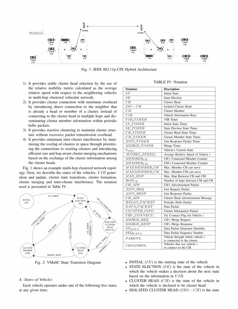
Fig. 1: IEEE 802.11p-LTE Hybrid Architecture
1) It provides stable cluster head selection by the use of
the relative mobility metric calculated as the average
relative speed with respect to the neighboring vehicles
in multi-hop clustered vehicular network.
2) It provides cluster connection with minimum overhead
by introducing direct connection to the neighbor that
is already a head or member of a cluster, instead of
connecting to the cluster head in multiple hops and dis-
seminating cluster member information within periodic
hello packets.
3) It provides reactive clustering to maintain cluster struc-
ture without excessive packet transmission overhead.
4) It provides minimum inter-cluster interference by mini-
mizing the overlap of clusters in space through prioritiz-
ing the connections to existing clusters and introducing
efficient size and hop aware cluster merging mechanisms
based on the exchange of the cluster information among
the cluster heads.
Fig. 1 shows an example multi-hop clustered network topol-
ogy. Next, we describe the states of the vehicles, V IB gener-
ation and update, cluster state transitions, cluster formation,
cluster merging and inter-cluster interference. The notation
used is presented in Table IV.
INITIAL
(IN)
STATE
ELECTION
(SE)
IN_TIMER
ISOLATED
CLUSTER
HEAD
(ISO-CH)
CH
_C
ON
DIT
ION
CH
_T
IME
R
ME
MB
ER
CH
= 0
CLUSTER
MEMBER
(CM)MERGE_RESP
CLUSTER
HEAD
(CH)
Fig. 2: VMaSC State Transition Diagram
A. States of Vehicles
Each vehicle operates under one of the following five states
at any given time:
TABLE IV: Notation
Notation Description
IN Initial State
SE State Election
CH Cluster Head
ISO − CH Isolated Cluster Head
CM Cluster Member
V IB Vehicle Information Base
V IB TIMER VIB Timer
IN TIMER Initial State Timer
SE TIMER State Election State Timer
CH TIMER Cluster Head State Timer
CM TIMER Cluster Member State Timer
JOIN TIMER Join Response Packet Timer
MERGE TIMER Merge Timer
Vstate Vehicle’s Current State
AV GREL SPEEDi Average Relative Speed of Vehicle i
MEMBERCH CH’s Connected Member Counter
MEMBERCM CM’s Connected Member Counter
MAXMEMBER CH Max. Member CH can serve
MAXMEMBER CM Max. Member CM can serve
MAX HOP Max. Hop Between CH and CM
HOPCM Number of hops between CM and CH
CH ADV CH’s Advertisement Packet
JOIN REQ Join Request Packet
JOIN RESP Join Response Packet
CH ADV Cluster Head Advertisement Message
HELLO PACKET Periodic Hello Packet
DATA PACKET Data Packet
CLUSTER INFO Cluster Information Packet
TRY CONNECT i Try Connect Flag for Vehicle i
MERGE REQ CH’s Merge Request
MERGE RESP CH’s Merge Response
IDDATA Data Packet Generator Identifier
SEQDATA Data Packet Sequence Number
PARENTiVehicle through which vehicle iis connected to the cluster
CHILDRENiVehicles that use vehicle ito connect to the CH
• INITIAL (IN ) is the starting state of the vehicle.
• STATE ELECTION (SE) is the state of the vehicle in
which the vehicle makes a decision about the next state
based on the information in V IB.
• CLUSTER HEAD (CH) is the state of the vehicle in
which the vehicle is declared to be cluster head.
• ISOLATED CLUSTER HEAD (ISO−CH) is the state
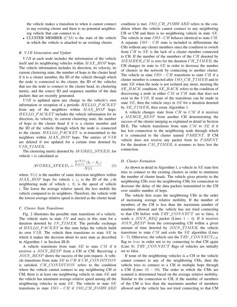
the vehicle makes a transition to when it cannot connect
to any existing cluster and there is no potential neighbor-
ing vehicle that can connect to it.
• CLUSTER MEMBER (CM ) is the state of the vehicle
in which the vehicle is attached to an existing cluster.
B. V IB Generation and Update
V IB at each node includes the information of the vehicle
itself and its neighboring vehicles within MAX HOP hops.
The vehicle information includes its direction, its velocity, its
current clustering state, the number of hops to the cluster head
if it is a cluster member, the ID of the vehicle through which
the node is connected to the cluster, the ID of the vehicles
that use the node to connect to the cluster head, its clustering
metric, and the source ID and sequence number of the data
packets that are recently generated.
V IB is updated upon any change in the vehicle’s own
information or reception of a periodic HELLO PACKETfrom any of the neighbors within MAX HOP hops.
HELLO PACKET includes the vehicle information for its
direction, its velocity, its current clustering state, the number
of hops to the cluster head if it is a cluster member and
the ID of the vehicle through which the node is connected
to the cluster. HELLO PACKET is re-transmitted to the
neighbors within MAX HOP hops. The entries of V IBare deleted if not updated for a certain time denoted by
V IB TIMER.
The clustering metric denoted by AV GREL SPEEDi for
vehicle i is calculated as
AV GREL SPEEDi =
∑N(i)j=1 |Si − Sij |
N(i)(1)
where N(i) is the number of same direction neighbors within
MAX HOP hops for vehicle i, ij is the ID of the j-th
neighboring node of vehicle i, Si is the speed of vehicle
i. The lower the average relative speed, the less mobile the
vehicle compared to its neighbors. Therefore, the vehicle with
the lowest average relative speed is elected as the cluster head.
C. Cluster State Transitions
Fig. 2 illustrates the possible state transitions of a vehicle.
The vehicle starts in state IN and stays in this state for a
duration denoted by IN TIMER. The periodic exchange
of HELLO PACKET in this state helps the vehicle build
its own V IB. The vehicle then transitions to state SE in
which it makes the decision about its next state as described
in Algorithm 1 in Section III-D.
A vehicle transitions from state SE to state CM if it
receives a JOIN RESP from a CH or CM. Receiving a
JOIN RESP shows the success of the join request. A vehi-
cle transitions from state SE to CH if CH CONDITIONis satisfied. CH CONDITION refers to the condition
where the vehicle cannot connect to any neighboring CH or
CM, there is at least one neighboring vehicle in state SE and
the vehicle has minimum average relative speed among all the
neighboring vehicles in state SE. The vehicle in state SEtransitions to state ISO − CH if ISO CH FORWARD
condition is met. ISO CH FORWARD refers to the con-
dition where the vehicle cannot connect to any neighboring
CH or CM and there is no neighboring vehicle in state SE.
The vehicle in state ISO−CH behaves identical to state CH .
A separate ISO − CH state is included to differentiate the
CHs without any cluster members since the condition to switch
from CH to SE is the lack of a cluster member connected
to CH. If the number of the members of the CH denoted by
MEMBER CH is zero for the duration CH TIMER, the
CH changes its state to SE in order to decrease the number
of clusters in the network by connecting to another cluster.
The vehicle in state ISO − CH transitions to state CH if a
cluster member is connected after ISO CH TIMER and to
state SE when the node is not isolated any more, meeting the
SE BACK condition. SE BACK refers to the condition of
discovering a node in either CM or CH state that does not
exist in the V IB. If none of the transitions can be made in
state SE, then the vehicle stays in SE for a duration denoted
by SE TIMER, then rerun Algorithm 1.
A vehicle changes state from CH to CM if it receives
a MERGE RESP from another CH demonstrating the
success of the cluster merging as explained in detail in Section
III-E. The vehicle transitions from state CM to SE if it
has lost connection to the neighboring node through which
it is connected to the cluster named PARENT . If CM
vehicle does not receive any packet from its PARENTfor the duration CM TIMER, it assumes to have lost the
connection.
D. Cluster Formation
As shown in detail in Algorithm 1, a vehicle in SE state first
tries to connect to the existing clusters in order to minimize
the number of cluster heads. The vehicle gives priority to the
neighboring CHs over the neighboring CMs for connection to
decrease the delay of the data packets transmitted to the CH
over smaller number of hops.
The vehicle first scans the neighboring CHs in the order
of increasing average relative mobility. If the number of
members of the CH is less than the maximum number of
members allowed and the vehicle has not tried connecting
to that CH before with TRY CONNECT set to false, it
sends a JOIN REQ packet (Lines 1 − 4). If it receives
JOIN RESP from the corresponding CH within a given
amount of time denoted by JOIN TIMER, the vehicle
transitions to state CM and exits the SE algorithm (Lines
5−7). Otherwise, the vehicle sets the TRY CONNECTCH
flag to true in order not to try connecting to that CH again
(Line 9). TRY CONNECT flags of vehicles are initially
set to false.
If none of the neighboring vehicles is a CH or the vehicle
cannot connect to any of the neighboring CHs, then the
vehicle tries to connect to a CH in multiple hops through
a CM (Lines 10 − 19). The order in which the CMs are
scanned is determined based on the average relative mobility.
Similar to the connection to CH, if the number of members
of the CM is less than the maximum number of members
allowed and the vehicle has not tried connecting to that CM

Algorithm 1: State Election (SE) Algorithm
1 forall the CH ∈ V IB do
2 if TRY CONNECTCH == false then
3 if MEMBERCH < MAXMEMBER CHthen
4 Send JOIN REQ;
5 if JOIN RESP received then
6 Vstate = CM ;
7 Exit;
8 else
9 TRY CONNECTCH = true;
10 forall the CM ∈ V IB do
11 if TRY CONNECTCM == false then
12 if MEMBERCM ¡ MAXMEMBER CMthen
13 if HOPCM < MAX HOP then
14 Send JOIN REQ;
15 if JOIN RESP received then
16 Vstate = CM ;
17 Exit;
18 else
19 TRY CONNECTCM = true;
20 if Not exists SE ∈ V IB then
21 Vstate = ISO − CH;
22 Exit;
23 else if AV GREL SPEEDcurr =minSE∈V IB(AV GREL SPEEDSE) then
24 Vstate = CH;
25 Broadcast CH ADV ;
26 Exit;
before with TRY CONNECT set to false (Lines 10− 12),
and the vehicle is within MAX HOP hops away from the
corresponding CH (Line 13), the vehicle sends JOIN REQpacket to this CM (Line 14). Depending on the reception of
the JOIN RESP , the vehicle then either transfers to state
CM or sets the try connect flag of the CM to true (Lines
15−19). If the vehicle receives multiple JOIN RESP s then
it prefers CH over CM and the vehicle with the smallest
average relative mobility among multiple CHs and CMs.
If the vehicle cannot connect to any CH or CM, the vehicle
checks the neighboring vehicles in SE state. If there is no such
vehicle, it transitions to state ISO − CH (Lines 20− 22). If
there are vehicles in SE state in its V IB and the vehicle has
the smallest average relative speed, it makes a transition to
CH state and broadcasts CH ADV packet (Lines 23− 26).
Otherwise, the vehicle stays in state SE for SE TIMER du-
ration and rerun Algorithm 1. This cluster formation technique
constructs hierarchical organization between vehicles where an
efficient aggregation algorithm can be implemented [40] and
applied by vehicles before forwarding data packets to parent
vehicle.
E. Cluster Merging
Since the vehicles do not send the JOIN REQ messages
to the CH in multiple hops, the CH learns about the ve-
hicles within its cluster via the HELLO PACKET . The
CH keeps the information about its cluster including the ID
and PARENT node of its cluster members and its cluster
direction within a data structure named CLUSTER INFO.
When two CHs become neighbors, they first check whether
they stay neighbors for a certain time period denoted
by MERGE TIMER. The value of MERGE TIMERshould be chosen to balance the trade-off between clus-
ter stability and number of clusters in the network: As
MERGE TIMER increases, the cluster stability increases
at the cost of increase in the number of clusters. If the
CHs stay neighbors for MERGE TIMER, they share their
CLUSTER INFO and their average relative speed with
each other. Both CHs then check the feasibility of the merged
cluster formed when the CH with higher average relative speed
gives up its CH role and connects to the CH with lower
average relative speed. A feasible merged cluster requires that
both clusters have the same cluster direction, the number of
members of the CH and CMs in the merged cluster be less
than MAXMEMBER CH and MAXMEMBER CMrespectively, and the number of hops in the merged cluster
be less than MAX HOP . Limiting the maximum number
of vehicles and the number of hops in the merged cluster
eliminates cluster head bottleneck and longer hierarchical
routes respectively. If the merged cluster is determined to be
feasible then the CH with higher average relative speed sends
MERGE REQ to the less mobile CH. If this CH receives
MERGE RESP , it gives up its CH role and informs its
cluster members about the merge operation. Otherwise, the
CHs continue to function as cluster heads. If the vehicle
receives multiple MERGE RESP s then it prefers the CH
with the smallest average relative mobility.
F. Inter-cluster Interference
Inter-cluster interference occurs when the clusters overlap
in space. Inter-cluster interference leads to higher medium
contention and inefficient flooding. VMaSC minimizes over-
lapping clusters via two methods. 1) The vehicles in SEstate try to join to an existing cluster first before declaring
themselves as CH or ISO−CH . 2) The CHs that are within
the transmission range of each other merge their clusters if
the resulting merged cluster is considered feasible. Moreover,
the data packets of the CMs are unicast to their PARENTto decrease the medium contention and increase the efficiency
of the flooding. Furthermore, the packets of each cluster are
only broadcast within that cluster identified with a unique ID
avoiding unnecessary flooding among multiple clusters.
G. Theoretical Analysis of VMaSC Clustering
In this section, we provide the theoretical analysis of the
relative speed metric used in the VMaSC clustering.
Let us assume that two neighboring vehicles 1 and 2 have
average speed v1 and v2, and average acceleration a1 and
a2, respectively. Assume that these vehicles move on a one
dimensional road and they communicate with each other only
if they are within the transmission range of each other called
rt. Let the location of the vehicles 1 and 2 on the road in
the moving direction be l1 and l2 with difference denoted
by r12 equal to l1 − l2. r12 is a random variable that takes
values within [−rt, rt] interval. The inter-vehicle distance has
been shown to have exponential distribution at low vehicle
density and log-normal distribution at high vehicle density
[6]. In this case, it should also be conditioned on the fact
that its value is in the [−rt, rt] range. We represent the
distribution of r12 by P (r12) without making any assumption
on its distribution except that it is limited to [−rt, rt] range
and symmetric around 0. Since the vehicles exchange their
speed information with each other, we assume that v1 and v2are predetermined. The average acceleration of the vehicles
a1 and a2 however are assumed to be random variables.
Most theoretical analyses related to clustering in the literature
assume no vehicle acceleration, i.e. a1 = a2 = 0 [41]–
[43]. The Freeway mobility model on the other hand assumes
a1 and a2 are independent random variables with uniform
distribution in the interval [−a, a], where a is determined by
the maximum acceleration and deceleration of the vehicles,
while also enforcing the minimum and maximum speed values
for the vehicles and the minimum safety distance between any
two vehicles, generating a possibly non-zero correlation on the
values of the accelerations a1 and a2; whereas Reference Point
Group Mobility Model determines the speed of each vehicle by
randomly deviating from the speed of a vehicle in their group
as a function of a predetermined speed and angle deviation
ratio [44], [45]. To encompass all these different mobility
models while preserving the tractability of the analysis, we
assume that the distribution of the difference between a1 and
a2, δ12, denoted by f(δ12) is symmetric around 0 and a
decreasing function of δ12 for δ12 > 0.
Let us first condition on the values of a1 and a2. At any
time T , if r12+(v1− v2)T +(a1−a2)T2/2 is less than rt in
magnitude, the two vehicles can communicate with each other.
In order to have a more stable link among the cluster members,
at any given time T , we need to maximize the probability that
the vehicles can communicate with each other given by
P (−rt < r12 + (v1 − v2)T + (a1 − a2)T2/2 < rt)
=
∫ rt
−rt
P (−rt − r12 < (v1 − v2)T + (a1 − a2)T2/2
< rt − r12|r12 = τ)P (τ)dτ (2)
where P (−rt − r12 < (v1 − v2)T + (a1 − a2)T2/2 <
rt − r12|r12 = τ) takes value 1 or 0 depending on the values
of τ , v1 − v2, a1 − a2, rt and T parameters. By using the
symmetry of the distribution P (r12) around 0, this probability
can be simplified as
∫ rt−|(v1−v2)T+(a1−a2)T2/2|
−rt
P (τ)dτ (3)
If a1 = a2, then to maximize this connection probability, we
need to minimize the relative speed of the vehicles given by
|v1 − v2|. On the other hand, if a1 6= a2, the probability that
the two vehicles are in communication range with each other
is given by
∫ ∞
−∞
P (−rt < r12+(v1−v2)T+δ12T2/2 < rt)f(δ12)dδ12
=
∫ ∞
−∞
∫ rt−|(v1−v2)T+δ12T2/2|
−rt
P (τ)f(δ12)dτdδ12 (4)
By using the symmetry of the distribution f(δ12) around 0,
this probability can be simplified as
∫ ∞
0
(
∫ rt−|(v1−v2)T+δ12T2/2|
−rt
P (τ)dτ+
∫ rt−|(v1−v2)T−δ12T2/2|
−rt
P (τ)dτ)f(δ12)dδ12 (5)
By using the fact that both |(v1 − v2)T + δ12T2/2| and
|(v1− v2)T − δ12T2/2| are lower bounded by ||(v1− v2)T |−
|δ12T2/2|| and upper bounded by |(v1−v2)T |+|δ12T
2/2|, the
probability that the two vehicles are in communication range
with each other is lower bounded by
2
∫ ∞
0
∫ rt−|(v1−v2)T |−δ12T2/2
−rt
P (τ)f(δ12)dτdδ12 (6)
and upper bounded by
2
∫ ∞
0
∫ rt−||(v1−v2)T |−δ12T2/2|
−rt
P (τ)f(δ12)dτdδ12 (7)
To maximize both lower bound and upper bound of this
probability, we need to again minimize the relative speed of
the vehicles |v1 − v2|.
IV. DATA DISSEMINATION IN HYBRID ARCHITECTURE
The goal of the proposed multi-hop cluster based IEEE
802.11p-LTE hybrid architecture is to disseminate the data
generated in the network to all the vehicles within a geograph-
ical area with small delay and high data packet delivery ratio.
LTE is used in this architecture to provide the connectivity
of the nodes even when the IEEE 802.11p based network is
disconnected within the dissemination distance, and improve
the delay and reliability performance of the transmissions
when the IEEE 802.11p based network has high node density
leading to high medium access contention.
The data forwarding at a vehicle depends on its clustering
state. If its clustering state is SE, the vehicle broadcasts the
DATA PACKET so that it reaches a member of a cluster
in the network. If the clustering state of the vehicle generating
or receiving a DATA PACKET is CM (CH), the vehicle
runs Algorithm 2 (Algorithm 3). The data flow is as follows:
1) Unicast from CM to its CH (if the vehicle is a CM)
2) Broadcast from CH to all its members and to the eNodeB
3) Unicast from eNodeB to EPC
4) Multicast from EPC to the neighboring eNodeBs cov-
ering a part of the geographical area targeted for the
dissemination of the DATA PACKET .

5) Multicast from eNodeBs to the CHs within their cover-
age.
6) Broadcast from the CHs to all its members.
As provided in Algorithm 2, if the CM generates or receives
a DATA PACKET , then it checks its V IB to determine
whether the packet has already been received (Lines 2−3). If
the CM receives the packet for the first time, then it checks
the source of the packet. If it is coming from its parent vehicle
(PARENTcurr) in the cluster, then it multicasts the packet
to all its children CHILDRENcurr (Lines 4−5). Otherwise,
the packet is from either one of its children or another vehicle
that is in SE state. The vehicle then unicasts the packet to
its parent vehicle for the dissemination of the packet to the
corresponding CH (Lines 6− 7) and updates its V IB for the
packet (Line 8).
Likewise, as provided in Algorithm 3, if the CH generates
or receives a DATA PACKET for the first time, it checks
the source of the packet (Lines 1−3). If the packet is coming
from eNodeB, the CH broadcasts the DATA PACKET to
all the members of its cluster (Lines 4 − 5). Otherwise, the
packet comes from itself, one of its children or another vehicle
in SE state. In that case, it broadcasts the packet to the
members of its cluster, creates an LTE DATA PACKETcontaining the data of the received packet, forwards the
LTE DATA PACKET to the eNodeB (Lines 6 − 8) and
updates its V IB for the packet (Line 9).
Upon reception of the LTE DATA PACKET from a
CH, the eNodeB multicasts the packet to all the CHs within
its coverage and forwards it to the EPC via a wired network.
The EPC then determines all the eNodeBs that cover an area
within the dissemination region of the corresponding packet.
The eNodeBs that receive an LTE DATA PACKET from
EPC then multicast it to all the CHs under their coverage,
which again disseminate the data to their CMs.
Algorithm 2: IEEE 802.11p-LTE CM Algorithm
1 On DATA PACKET generation or receipt:
2 Extract IDDATA and SEQDATA;
3 if (IDDATA, SEQDATA) 6∈ V IB then
4 if DATA PACKET is from PARENTcurr then
5 Multicast DATA PACKET to
CHILDRENcurr;
6 else
7 Unicast DATA PACKET to PARENTcurr;
8 Update V IB;
V. PERFORMANCE EVALUATION
The simulations are performed in the Network Simulator
ns3 (Release 3.17) [46] with the realistic mobility of the
vehicles generated by SUMO [28]. SUMO, generated by
the German Aerospace Center, is an open-source, space-
continuous, discrete-time traffic simulator capable of modeling
the behavior of individual drivers. The acceleration and over-
taking decision of the vehicles are determined by using the
Algorithm 3: IEEE 802.11p-LTE CH Algorithm
1 On DATA PACKET generation or receipt:
2 Extract IDDATA and SEQDATA;
3 if (IDDATA, SEQDATA) 6∈ V IB then
4 if DATA PACKET is from eNodeB then
5 Broadcast DATA PACKET into cluster;
6 else
7 Broadcast DATA PACKET into cluster;
8 Put data in LTE DATA PACKET and
forward it to eNodeB;
9 Update V IB;
distance to the leading vehicle, traveling speed, dimension of
vehicles and profile of acceleration-deceleration.
The goal of the simulations is to compare the performance
of the proposed multi-hop cluster based IEEE 802.11p-LTE
hybrid architecture to the previously proposed VANET multi-
hop clustering algorithms NHop [9] and MDMAC [16], the
hybrid architectures built with the usage of these clustering
algorithms NHop and MDMAC, and flooding based message
dissemination.
The road topology consists of a two-lane and two-way
road of length 5 km. The vehicles are injected into the
road according to a Poisson process with rate equal to 2vehicles per second. The total simulation time is 355 s. The
clustering process starts at 55 s when all the vehicles have
entered the road. All the performance metrics are evaluated
for the remaining 300 s. Two classes of vehicles with different
maximum speed ranges are used in the simulation in order to
create a realistic scenario with different types of vehicles on
the road such as passenger cars, buses, trucks. The first vehicle
class has maximum speed of 10 m/s whereas the maximum
speed of the second vehicle class is considered as a variable
ranging from 10 m/s to 35 m/s. Considering the injection of the
vehicles into the road and their maximum speed constraint, the
average number of the neighbors of the vehicles ranges from
10 to 18 at different times for different scenarios.
Tables V and VI list the simulation parameters of the
VANET and LTE networks respectively. Maximum num-
ber of hops within a cluster is chosen in the range [1, 3]since the number of hops above 3 reduces the clustering
stability considerably due to the increase in the number
of HELLO PACKET s disseminated within the maximum
number of hops, increase in the number of retransmitted
packets lost due to higher contention, and increase in the
number of connections lost among the cluster members due
to higher packet collisions. YANS channel model [47] used
throughout the simulation is based on first deciding whether
or not packet can be received at the beginning of the packet
transmission considering the physical layer and Signal-to-
Noise-Plus-Interference Ratio (SINR) level then determining
the successful reception of the packet probabilistically at the
end of the packet transmission by calculating the packet
error rate as a function of the SINR level, modulation type,
transmission rate and error correcting code.
We first compare the stability of the proposed clustering al-
gorithm VMaSC to the previously proposed multi-hop VANET
clustering algorithms. We then examine the delay and data
packet delivery ratio performance of the proposed hybrid
architecture compared to both previously proposed cluster
based hybrid architectures and alternative mechanisms includ-
ing flooding and pure VANET cluster based data forwarding.
TABLE V: ns-3 Simulation Parameters For VANET
Parameters Value
Simulation Time 300 s
Maximum Velocity 10 - 35 m/s
MAX HOP 1, 2, 3
Number of Vehicles 100
Transmission Range 200 m
MAC Layer DCF, CSMA/CA
Channel Model YANS [47]
MAXMEMBERCH 5
MAXMEMBERCM 1
HELLO PACKET period 200 ms
HELLO PACKET size 64 bytes
DATA PACKET period 1 s
DATA PACKET size 1024 bytes
V IB TIMER 1 s
IN TIMER 2 s
SE TIMER 2 s
CH TIMER 2 s
CM TIMER 2 s
JOIN TIMER 2 s
MERGE TIMER 2 s
MAX HOP 1, 2, 3
TABLE VI: ns-3 Simulation Parameters For LTE
Parameters Value
eNodeB Scheduler Type RrFfMacScheduler
eNodeB Coverage 7 km
Pathloss Model Friis Propagation Model
A. VANET Clustering
In this section, VMaSC is compared to multi-hop clustering
algorithms NHop [9] and MDMAC [16], the characteristics of
which are summarized in Table III. The performance metrics
used for comparison are cluster head duration, cluster member
duration, cluster head change rate, clustering overhead and
number of vehicles in SE state.
1) Cluster Head Duration: Cluster head duration is defined
as the time period from when a vehicle changes state to CHto when a vehicle transitions from state CH to state SE or
CM .
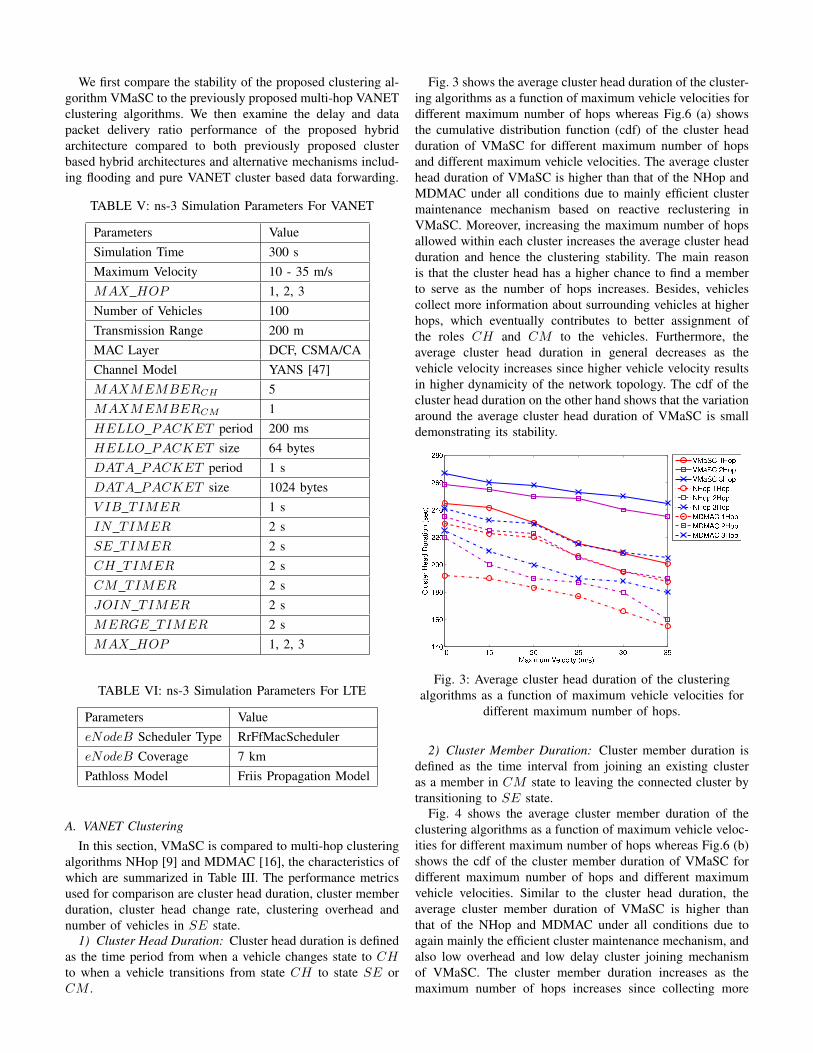
Fig. 3 shows the average cluster head duration of the cluster-
ing algorithms as a function of maximum vehicle velocities for
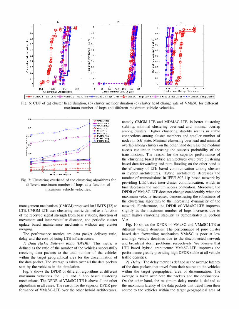
different maximum number of hops whereas Fig.6 (a) shows
the cumulative distribution function (cdf) of the cluster head
duration of VMaSC for different maximum number of hops
and different maximum vehicle velocities. The average cluster
head duration of VMaSC is higher than that of the NHop and
MDMAC under all conditions due to mainly efficient cluster
maintenance mechanism based on reactive reclustering in
VMaSC. Moreover, increasing the maximum number of hops
allowed within each cluster increases the average cluster head
duration and hence the clustering stability. The main reason
is that the cluster head has a higher chance to find a member
to serve as the number of hops increases. Besides, vehicles
collect more information about surrounding vehicles at higher
hops, which eventually contributes to better assignment of
the roles CH and CM to the vehicles. Furthermore, the
average cluster head duration in general decreases as the
vehicle velocity increases since higher vehicle velocity results
in higher dynamicity of the network topology. The cdf of the
cluster head duration on the other hand shows that the variation
around the average cluster head duration of VMaSC is small
demonstrating its stability.
✶� ✶✁ ✷� ✷✁ ✸� ✸✁✶✂�
✶✄�
✶☎�
✷��
✷✷�
✷✂�
✷✄�
✷☎�
▼✆✝✞✟✠✟ ✡☛☞✌✍✞✎✏ ✑✟✒✓✔
❈✕✖✗✘✙✚✛✙✜✢✣✖✚✜✘✤✥✦✧✗✙★✩
✡▼✆❱✪ ✶✫✌✬
✡▼✆❱✪ ✷✫✌✬
✡▼✆❱✪ ✸✫✌✬
◆✫✌✬ ✶✫✌✬
◆✫✌✬ ✷✫✌✬
◆✫✌✬ ✸✫✌✬
▼✭▼✮✪ ✶✫✌✬
▼✭▼✮✪ ✷✫✌✬
▼✭▼✮✪ ✸✫✌✬
Fig. 3: Average cluster head duration of the clustering
algorithms as a function of maximum vehicle velocities for
different maximum number of hops.
2) Cluster Member Duration: Cluster member duration is
defined as the time interval from joining an existing cluster
as a member in CM state to leaving the connected cluster by
transitioning to SE state.
Fig. 4 shows the average cluster member duration of the
clustering algorithms as a function of maximum vehicle veloc-
ities for different maximum number of hops whereas Fig.6 (b)
shows the cdf of the cluster member duration of VMaSC for
different maximum number of hops and different maximum
vehicle velocities. Similar to the cluster head duration, the
average cluster member duration of VMaSC is higher than
that of the NHop and MDMAC under all conditions due to
again mainly the efficient cluster maintenance mechanism, and
also low overhead and low delay cluster joining mechanism
of VMaSC. The cluster member duration increases as the
maximum number of hops increases since collecting more
information about surrounding vehicles at higher number of
hops enables the selection of better CH for connection. The cdf
of the cluster member duration on the other hand shows that
the variation around the average value of the cluster member
duration of VMaSC is minimal similar to that of the cluster
head duration.
10 15 20 25 30 35140
160
180
200
220
240
260
280
Maximum Velocity (m/s)
Clu
ster
Mem
ber
Dur
atio
n (s
ec)
VMaSC 1HopVMaSC 2HopVMaSC 3HopNHop 1HopNHop 2HopNHop 3HopMDMAC 1HopMDMAC 2HopMDMAC 3Hop
Fig. 4: Average cluster member duration of the clustering
algorithms as a function of maximum vehicle velocities for
different maximum number of hops.
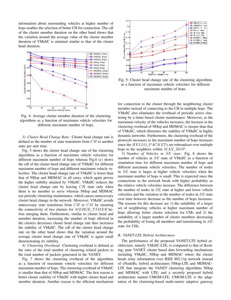
3) Cluster Head Change Rate: Cluster head change rate is
defined as the number of state transitions from CH to another
state per unit time.
Fig. 5 shows the cluster head change rate of the clustering
algorithms as a function of maximum vehicle velocities for
different maximum number of hops whereas Fig.6 (c) shows
the cdf of the cluster head change rate of VMaSC for different
maximum number of hops and different maximum vehicle ve-
locities. The cluster head change rate of VMaSC is lower than
that of NHop and MDMAC in all cases, which again proves
the higher stability attained by VMaSC. VMaSC reduces the
cluster head change rate by leaving CH state only when
there is no member to serve whereas NHop and MDMAC
use periodic clustering maintenance, which causes unnecessary
cluster head change in the network. Moreover, VMaSC avoids
unnecessary state transitions from CH to CM by ensuring
the connectivity of two clusters for MERGE TIMER be-
fore merging them. Furthermore, similar to cluster head and
member duration, increasing the number of hops allowed in
the clusters decreases cluster head change rate thus increases
the stability of VMaSC. The cdf of the cluster head change
rate on the other hand shows that the variation around the
average cluster head change rate of VMaSC is again small
demonstrating its stability.
4) Clustering Overhead: Clustering overhead is defined as
the ratio of the total number of clustering related packets to
the total number of packets generated in the VANET.
Fig. 7 shows the clustering overhead of the algorithms
as a function of maximum vehicle velocities for different
maximum number of hops. The clustering overhead of VMaSC
is smaller than that of NHop and MDMAC. The first reason is
better cluster stability of VMaSC with higher cluster head and
member duration. Another reason is the efficient mechanism
✶� ✶✁ ✷� ✷✁ ✸� ✸✁�✵�✂
�✵�✄
�✵�☎
�✵✶
�✵✶✷
�✵✶✂
�✵✶✄
�✵✶☎
�✵✷
�✵✷✷
▼✆✝✞✟✠✟ ✡☛☞✌✍✞✎✏ ✑✟✒✓✔
❈✕✖✗✘✙✚✛✙✜✢❈✣✜✤✥✙✦✜✘✙✧★✗✩
✡▼✆❱✪ ✶✫✬✌✭
✡▼✆❱✪ ✷✫✬✌✭
✡▼✆❱✪ ✸✫✬✌✭
◆✬✌✭ ✶✫✬✌✭
◆✬✌✭ ✷✫✬✌✭
◆✬✌✭ ✸✫✬✌✭
▼✮▼✯✪ ✶✫✬✌✭
▼✮▼✯✪ ✷✫✬✌✭
▼✮▼✯✪ ✸✫✬✌✭
Fig. 5: Cluster head change rate of the clustering algorithms
as a function of maximum vehicle velocities for different
maximum number of hops.
for connection to the cluster through the neighboring cluster
member instead of connecting to the CH in multiple hops. The
VMaSC also eliminates the overhead of periodic active clus-
tering by a timer based cluster maintenance. Moreover, as the
maximum velocity of the vehicles increases, the increase in the
clustering overhead of NHop and MDMAC is steeper than that
of VMaSC, which illustrates the stability of VMaSC in highly
dynamic networks. Furthermore, the clustering overhead of the
protocols increases as the maximum number of hops increases
since the HELLO PACKET s are rebroadcast over multiple
hops to the neighbors within MAX HOP .
5) Number of Vehicles in SE state: Fig. 8 shows the
number of vehicles in SE state of VMaSC as a function of
simulation time for different maximum number of hops and
different maximum vehicle velocities. The number of nodes
in SE state is larger at higher vehicle velocities when the
maximum number of hops is small. This is expected since the
connections in the network break with higher probability as
the relative vehicle velocities increase. The difference between
the number of nodes in SE state at higher and lower vehicle
velocities and the variation in the number of nodes in SE state
over time however decrease as the number of hops increases.
The reasons for this decrease are 1) the suitability of a larger
set of neighboring vehicles at higher maximum number of
hops allowing better cluster selection for CMs and 2) the
suitability of a larger number of cluster members decreasing
the probability of losing all members and transitioning to SEstate for CHs.
B. VANET-LTE Hybrid Architectures
The performance of the proposed VANET-LTE hybrid ar-
chitecture, namely VMaSC-LTE, is compared to that of flood-
ing; pure VANET cluster based data forwarding mechanisms
including VMaSC, NHop and MDMAC where the cluster
heads relay information over IEEE 802.11p network instead
of eNodeBs; hybrid architectures NHop-LTE and MDMAC-
LTE that integrate the VANET clustering algorithms NHop
and MDMAC with LTE; and a recently proposed hybrid
architecture named CMGM-LTE. CMGM-LTE is the adap-
tation of the clustering-based multi-metric adaptive gateway
✶�✁ ✷✁✁ ✷�✁ ✸✁✁
✁
✁✵✶
✁✵✷
✁✵✸
✁✵✂
✁✵�
✁✵✄
✁✵☎
✁✵✆
✁✵✝
✶
❈✞✟✠✡☛☞ ✌☛✍✎ ✏✟☞✍✡✑✒✓ ✔✠☛✕✖
✗✘✙✘✚✛✜✢✣✤✥✢✦✜✧✢★✘✜✢✩✪✫✘✪✬✜✢✩✪
✭✮✯
✰ ✺✰ ✱✰✰ ✱✺✰ ✲✰✰ ✲✺✰ ✳✰✰
✰
✰✴✱
✰✴✲
✰✴✳
✰✴✹
✰✴✺
✰✴✻
✰✴✼
✰✴✽
✰✴✾
✱
❈✞✟✠✡☛☞ ✿☛❀❁☛☞ ✏✟☞✍✡✑✒✓ ✔✠☛✕✖
✗✘✙✘✚✛✜✢✣✤✥✢✦✜✧✢★✘✜✢✩✪✫✘✪✬✜✢✩✪
✭❂✯
✰ ✰✴✰✺ ✰✴✱ ✰✴✱✺ ✰✴✲ ✰✴✲✺
✰
✰✴✱
✰✴✲
✰✴✳
✰✴✹
✰✴✺
✰✴✻
✰✴✼
✰✴✽
✰✴✾
✱
❈✞✟✠✡☛☞ ✌☛✍✎ ❈❃✍✓❄☛ ❅✍✡☛ ✔❆✠☛✕✖
✗✘✙✘✚✛✜✢✣✤✥✢✦✜✧✢★✘✜✢✩✪✫✘✪✬✜✢✩✪
✭❇✯
❱✿✍❉❈ ✶❊✌✒❋ ✶✁❀❆✠ ❱✿✍❉❈ ✷❊✌✒❋ ✶✁ ❀❆✠ ❱✿✍❉❈ ✸❊✌✒❋ ✶✁ ❀❆✠ ❱✿✍❉❈ ✶❊✌✒❋ ✸�❀❆✠ ❱✿✍❉❈ ✷❊✌✒❋ ✸�❀❆✠ ❱✿✍❉❈ ✸❊✌✒❋ ✸� ❀❆✠
Fig. 6: CDF of (a) cluster head duration, (b) cluster member duration (c) cluster head change rate of VMaSC for different
maximum number of hops and different maximum vehicle velocities.
●❍ ●■ ❏❍ ❏■ ❑❍ ❑■❍
●❍
❏❍
❑❍
▲❍
■❍
▼❍
◆❖P◗❘❙❘ ❚❯❲❳❨◗❩❬ ❭❘❪❫❴
❵❛❜❝❞❡❢❣❤✐❥❦❡❢❧❡♠♥♦♣q
❚◆❖rs ●t❳✉
❚◆❖rs ❏t❳✉
❚◆❖rs ❑t❳✉
✈t❳✉ ●t❳✉
✈t❳✉ ❏t❳✉
✈t❳✉ ❑t❳✉
◆✇◆①s ●t❳✉
◆✇◆①s ❏t❳✉
◆✇◆①s ❑t❳✉
Fig. 7: Clustering overhead of the clustering algorithms for
different maximum number of hops as a function of
maximum vehicle velocities.
management mechanism (CMGM) proposed for UMTS [32] to
LTE. CMGM-LTE uses clustering metric defined as a function
of the received signal strength from base stations, direction of
movement and inter-vehicular distance, and periodic cluster
update based maintenance mechanism without any cluster
merging.
The performance metrics are data packet delivery ratio,
delay and the cost of using LTE infrastructure.
1) Data Packet Delivery Ratio (DPDR): This metric is
defined as the ratio of the number of the vehicles successfully
receiving data packets to the total number of the vehicles
within the target geographical area for the dissemination of
the data packet. The average is taken over all the data packets
sent by the vehicles in the simulation.
Fig. 9 shows the DPDR of different algorithms at different
maximum velocities for 1, 2 and 3 hop based clustering
mechanisms. The DPDR of VMaSC-LTE is above all the other
algorithms in all cases. The reason for the superior DPDR per-
formance of VMaSC-LTE over the other hybrid architectures,
namely CMGM-LTE and MDMAC-LTE, is better clustering
stability, minimal clustering overhead and minimal overlap
among clusters. Higher clustering stability results in stable
connections among cluster members and smaller number of
nodes in SE state. Minimal clustering overhead and minimal
overlap among clusters on the other hand decrease the medium
access contention increasing the success probability of the
transmissions. The reason for the superior performance of
the clustering based hybrid architectures over pure clustering
based data forwarding and pure flooding on the other hand is
the efficiency of LTE based communication among clusters
in hybrid architectures. Hybrid architecture decreases the
number of transmissions in IEEE 802.11p based network by
providing LTE based inter-cluster communication, which in
turn decreases the medium access contention. Moreover, the
DPDR of VMaSC-LTE does not change considerably when the
maximum velocity increases, demonstrating the robustness of
the clustering algorithm to the increasing dynamicity of the
network. Furthermore, the DPDR of VMaSC-LTE improves
slightly as the maximum number of hops increases due to
again higher clustering stability as demonstrated in Section
V-A.
Fig. 10 shows the DPDR of VMaSC and VMaSC-LTE at
different vehicle densities. The performance of pure cluster
based data forwarding mechanism VMaSC is poor at low
and high vehicle densities due to the disconnected network
and broadcast storm problems, respectively. We observe that
LTE based hybrid architecture VMaSC-LTE improves the
performance greatly providing high DPDR stable at all vehicle
traffic densities.
2) Delay: The delay metric is defined as the average latency
of the data packets that travel from their source to the vehicles
within the target geographical area of dissemination. The
average is taken over both the packets and the destinations.
On the other hand, the maximum delay metric is defined as
the maximum latency of the data packets that travel from their
source to the vehicles within the target geographical area of

100 150 200 250 3000
5
10
15
20
25
30
Simulation Time (Sec)
Num
ber
Of V
ehic
les
in S
E
100 150 200 250 3000
5
10
15
20
25
30
Simulation Time (Sec)
Num
ber
Of V
ehic
les
in S
E
100 150 200 250 3000
5
10
15
20
25
30
Simulation Time (Sec)
Num
ber
Of V
ehic
les
in S
E
VMaSC 10 m/s VMaSC 35 m/s
Fig. 8: Number of vehicles in SE state for (a) 1-hop, (b) 2-hop (c) 3-hop VMaSC clustering
10 15 20 25 30 3510
20
30
40
50
60
70
80
90
100
Maximum Velocity (m/s)
Dat
a P
acke
t Del
iver
y R
atio
(%
)
(a)
10 15 20 25 30 3510
20
30
40
50
60
70
80
90
100
Maximum Velocity (m/s)
Dat
a P
acke
t Del
iver
y R
atio
(%
)
(b)
10 15 20 25 30 3510
20
30
40
50
60
70
80
90
100
Maximum Velocity (m/s)
Dat
a P
acke
t Del
iver
y R
atio
(%
)
(c)
Flooding VMaSC NHop MDMAC VMaSC−LTE NHOP−LTE MDMAC−LTE CMGM−LTE
Fig. 9: DPDR of data dissemination algorithms at different maximum velocities for (a) 1-hop, (b) 2-hop (c) 3-hop based
clustering
0.05 0.1 0.12 0.15 0.220
30
40
50
60
70
80
90
100
Vehicle Density (Vehicles/Meter)
Dat
a P
acke
t Del
iver
y R
atio
(%)
VMaSC 1−HopVMaSC 2−HopVMaSC 3−HopVMaSC−LTE 1−HopVMaSC−LTE 2−HopVMaSC−LTE 3−Hop
Fig. 10: DPDR of VMaSC and VMaSC-LTE at different
vehicle densities.
dissemination.
Figs. 11 and 12 show the average and maximum delay of
different algorithms at different maximum velocities for 1,2
and 3 hop based clustering mechanisms respectively. When
we consider these results together with Fig. 9, we observe that
there is a trade-off between DPDR and delay for flooding and
pure cluster based algorithms: Flooding provides lower delay
than cluster based algorithms whereas cluster based algorithms
achieve higher DPDR than the flooding. LTE based hybrid
architectures on the other hand achieve both low delay and
high DPDR at the cost of using the infrastructure. Among the
hybrid architectures, VMaSC-LTE achieves the lowest delay.
Furthermore, the DPDR and delay analysis at different number
of maximum hops allowed within clusters show that increasing
the maximum number of hops increases the DPDR at the cost
of slight increase in the delay.
3) LTE Cost: LTE cost metric indicates the cost of using
LTE infrastructure to improve the data delivery performance
of the hybrid architecture and is measured by the number of
cluster heads in the network. The number of cluster heads
depends on both the number of hops used in the clustering
algorithm and the constraint on the maximum number of
members CH and CM can admit, denoted by MEMBERCH
and MEMBERCM respectively. We assume that the value
of MEMBERCH varies from 1 to 10 however the value of
MEMBERCM is kept constant at 1 in the simulation.

10 15 20 25 30 350
0.5
1
1.5
2
2.5
3
3.5
4
4.5
5(a)
Maximum Velocity (m/s)
Ave
rage
Del
ay (
sec)
10 15 20 25 30 350
0.5
1
1.5
2
2.5
3
3.5
4
4.5
5
Maximum Velocity (m/s)
Ave
rage
Del
ay (
sec)
(b)
10 15 20 25 30 350
0.5
1
1.5
2
2.5
3
3.5
4
4.5
5
Maximum Velocity (m/s)
Ave
rage
Del
ay (
sec)
(c)
Flooding VMaSC NHop MDMAC VMaSC−LTE NHop−LTE MDMAC−LTE CMGM−LTE
Fig. 11: Average delay of data dissemination algorithms at different maximum velocities for (a) 1-hop, (b) 2-hop (c) 3-hop
based clustering.
10 15 20 25 30 350
1
2
3
4
5
6
7
8(a)
Maximum Velocity (m/s)
Max
imum
Del
ay (
sec)
10 15 20 25 30 350
1
2
3
4
5
6
7
8(b)
Maximum Velocity (m/s)
Max
imum
Del
ay (
sec)
10 15 20 25 30 350
1
2
3
4
5
6
7
8(c)
Maximum Velocity (m/s)
Max
imum
Del
ay (
sec)
Flooding VMaSC NHop MDMAC VMaSC−LTE NHop−LTE MDMAC−LTE CMGM−LTE
Fig. 12: Maximum delay of data dissemination algorithms at different maximum velocities for (a) 1-hop, (b) 2-hop (c) 3-hop
based clustering.
TABLE VII: Number of clusters (LTE cost) of VMaSC-LTE
for different MEMBERCH and number of hops values.
Number of Clusters
MEMBERCH 1-Hop 2-Hop 3-Hop
1 72 65 48
3 52 50 49
5 42 38 35
10 32 42 38
Table VII shows the number of clusters, i.e. number of clus-
ter heads, for different MEMBERCH and number of hops
values. As MEMBERCH increases, the number of clusters
in general decreases. The number of clusters however may
increase back when the number of hops and MEMBERCH
are high, e.g. MEMBERCH = 10 at 2-hop scenario, due to
the higher clustering overhead at the CHs, higher contention
around CHs and larger number of CMs affected when a link
within the cluster breaks. When both the number of hops and
MEMBERCH are high in a cluster, the number of vehicles
connected or sending a request for connection to the CH is
higher. Moreover, the number of packets traveling to the CH
is larger. Therefore, there exists a lot of contention around the
CH. This results in the loss of packets around CH so loss of
connections to the parent node in the routing path to the CH.
When the connection of a vehicle to its parent node breaks,
the vehicle and all of its children transition back to SE state,
increasing clustering overhead further and possibly creating
unnecessarily higher number of clusters.
Fig. 13 shows the dependence of the DPDR on the
MEMBERCH for different number of maximum allowed
hops. We observe that the DPDR increases up to 100 as
MEMBERCH decreases. The main reason for this behavior
is the decrease in the clustering overhead and contention
in the IEEE 802.11p based network with the decrease in
MEMBERCH . This demonstrates the adaptive usage of
the VMaSC-LTE architecture depending on the reliability
requirement of the application. As the reliability requirement
of the application increases, the value of the MEMBERCH

1 3 5 1094
95
96
97
98
99
100
MEMBERCH
Dat
a P
acke
t Del
iver
y R
atio
(%
)
VMaSC−LTE 1−HopVMaSC−LTE 2−HopVMaSC−LTE 3−Hop
Fig. 13: DPDR of VMaSC-LTE for different
MEMBERCH and number of hops values.
parameter needs to decrease at the cost of creating a larger
number of clusters so increasing the cost of LTE usage.
VI. CONCLUSION
In this paper, we introduce a novel architecture VMaSC-LTE
that integrates 3GPP/LTE networks with IEEE 802.11p based
VANET networks. In VMaSC-LTE, vehicles are clustered in
a multi-hop based novel approach named VMaSC with the
features of cluster head selection using the relative mobility
metric calculated as the average relative speed with respect
to the neighboring vehicles, cluster connection with minimum
overhead by introducing direct connection to the neighbor that
is already a head or member of a cluster instead of connecting
to the cluster head in multiple hops, disseminating cluster
member information within periodic hello packets, reactive
clustering to maintain cluster structure without excessive con-
sumption of network resources, and efficient size and hop
limited cluster merging mechanism based on the exchange
of the cluster information among the cluster heads. In the
constructed clusters, cluster heads activate the LTE interface
to connect the VANET network to LTE.
Extensive simulations in ns-3 with the vehicle mobility
input from SUMO demonstrate the superior performance of
VMaSC-LTE over both previously proposed hybrid architec-
tures and alternative routing mechanisms including flooding
and cluster based routing. We observe that the DPDR perfor-
mance of pure cluster based data forwarding mechanism is
poor at low and high vehicle densities due to the disconnected
network and broadcast storm problems respectively. LTE based
hybrid architecture however improves the performance greatly
providing high DPDR stable at all vehicle traffic densities.
Moreover, despite the trade-off between DPDR and delay
observed for flooding and pure cluster based algorithms, the
proposed architecture has been demonstrated to achieve both
low delay and high DPDR at the cost of using the LTE
infrastructure. Among the hybrid architectures, VMaSC-LTE
achieves the lowest delay and highest DPDR due to better
clustering stability, minimal clustering overhead and minimal
overlap among clusters. The DPDR and delay analysis at
different number of maximum hops allowed within clusters
shows that increasing the maximum number of hops up to 3increases the DPDR at the cost of slight increase in the delay.
We have also defined LTE cost metric as the cost of using
LTE infrastructure to improve the data delivery performance
of the hybrid architecture. The LTE cost is measured by the
number of cluster heads in the network. We observe that the
DPDR increases up to 100 as the number of members allowed
in the clusters decreases. The main reason for this behavior is
the decrease in the clustering overhead and contention in the
IEEE 802.11p based network with the decrease in the number
of cluster members. This demonstrates the adaptive usage
of the VMaSC-LTE architecture depending on the reliability
requirement of the application. As the required reliability of
the application increases, the number of cluster members needs
to decrease at the cost of creating a larger number of clusters
so increasing the cost of LTE usage.
As future work, we aim to investigate the use of VMaSC-
LTE in urban traffic scenarios and extend VMaSC-LTE archi-
tecture with data aggregation and calculation of the clustering
metric with additional information such as the most probable
path information of the vehicles.
REFERENCES
[1] S. Ucar, S. C. Ergen, and O. Ozkasap, “VMaSC: Vehicular multi-hopalgorithm for stable clustering in vehicular ad hoc networks,” in Wireless
Communications and Networking Conference (WCNC), IEEE, 2013, pp.2381–2386.
[2] R. Chen, W.-L. Jin, and A. Regan, “Broadcasting safety informationin vehicular networks: issues and approaches,” Network, IEEE, vol. 24,no. 1, pp. 20 –25, 2010.
[3] “Vehicle Safety Communications Project Task 3 Final Report: IdentifyIntelligent Vehicle Safety Applications Enabled byDSRC,” in The CAMP
Vehicle Safety Communications Consortium,, June 2010.
[4] “Intelligent Transport Systems (ITS); Vehicular Communications; BasicSet of Applications; Definitions,” in The CAMP Vehicle Safety Commu-
nications Consortium,, June 2010.
[5] N. Wisitpongphan, O. Tonguz, J. Parikh, P. Mudalige, F. Bai, andV. Sadekar, “Broadcast storm mitigation techniques in vehicular ad hocnetworks,” Wireless Communications, IEEE, vol. 14, no. 6, pp. 84 –94,December 2007.
[6] N. Wisitpongphan, F. Bai, P. Mudalige, V. Sadekar, and O. Tonguz,“Routing in sparse vehicular ad hoc wireless networks,” Selected Areas
in Communications, IEEE Journal on, vol. 25, no. 8, pp. 1538–1556,2007.
[7] T. Song, W. Xia, T. Song, and L. Shen, “A cluster-based directionalrouting protocol in VANET,” in Communication Technology (ICCT),
12th IEEE International Conference on, 2010, pp. 1172–1175.
[8] B. Wiegel, Y. Gunter, and H. Grossmann, “Cross-layer design forpacket routing in vehicular ad hoc networks,” in Vehicular Technology
Conference VTC Fall. IEEE 66th, 2007, pp. 2169–2173.
[9] Z. Zhang, A. Boukerche, and R. Pazzi, “A novel multi-hop clusteringscheme for vehicular ad-hoc networks,” in Proceedings of the 9th ACM
international symposium on Mobility management and wireless access,2011, pp. 19–26.
[10] N. Maslekar, M. Boussedjra, J. Mouzna, and L. Houda, “Direction basedclustering algorithm for data dissemination in vehicular networks,” inVehicular Networking Conference (VNC), IEEE, 2009, pp. 1–6.
[11] H. Su and X. Zhang, “Clustering-based multichannel MAC protocolsfor QoS provisionings over vehicular ad hoc networks,” Vehicular
Technology, IEEE Transactions on, vol. 56, no. 6, pp. 3309–3323, 2007.
[12] M. Venkata, M. Pai, R. Pai, and J. Mouzna, “Traffic monitoring and rout-ing in VANETs- a cluster based approach,” in ITS Telecommunications
(ITST), 2011 11th International Conference on, 2011, pp. 27–32.
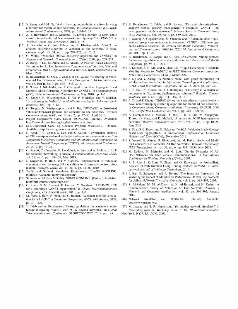
[13] Y. Zhang and J. M. Ng, “A distributed group mobility adaptive clusteringalgorithm for mobile ad hoc networks,” in Communications. ICC. IEEE
International Conference on, 2008, pp. 3161–3165.[14] Z. Y. Rawashdeh and S. Mahmud, “A novel algorithm to form stable
clusters in vehicular ad hoc networks on highways.” in EURASIP J.
Wireless Comm. and Networking, 2012, p. 15.[15] A. Daeinabi, A. G. Pour Rahbar, and A. Khademzadeh, “VWCA: an
efficient clustering algorithm in vehicular ad hoc networks,” J. Netw.
Comput. Appl., vol. 34, no. 1, pp. 207–222, Jan. 2011.[16] G. Wolny, “Modified DMAC clustering algorithm for VANETs,” in
Systems and Networks Communications. ICSNC, 2008, pp. 268–273.[17] Z. Wang, L. Liu, M. Zhou, and N. Ansari, “A Position-Based Clustering
Technique for Ad Hoc Intervehicle Communication,” Systems, Man, and
Cybernetics, Part C: Applications and Reviews, IEEE Transactions on,March 2008.
[18] B. Hassanabadi, C. Shea, L. Zhang, and S. Valaee, “Clustering in Vehic-ular Ad Hoc Networks using Affinity Propagation,” Ad Hoc Networks,vol. 13, Part B, no. 0, pp. 535 – 548, 2014.
[19] E. Souza, I. Nikolaidis, and P. Gburzynski, “A New Aggregate LocalMobility ALM; Clustering Algorithm for VANETs,” in Communications
(ICC), IEEE International Conference on, May 2010, pp. 1–5.[20] O. Tonguz, N. Wisitpongphan, F. Bai, P. Mudalige, and V. Sadekar,
“Broadcasting in VANET,” in Mobile Networking for Vehicular Envi-
ronments, 2007, pp. 7–12.[21] O. Tonguz, N. Wisitpongphan, and F. Bai, “DV-CAST: A distributed
vehicular broadcast protocol for vehicular ad hoc networks,” Wireless
Communications, IEEE, vol. 17, no. 2, pp. 47–57, April 2010.[22] Project Cooperative Cars, CoCar @ONLINE. [Online]. Available:
http://www.aktiv-online.org/english/aktiv-cocar.html/[23] LTE-Connected Cars, ng Connect Program @ONLINE. [Online].
Available: http://www.ngconnect.org/index.htm/[24] H. Abid, T.-C. Chung, S. Lee, and S. Qaisar, “Performance analysis
of LTE smartphones-based vehicle-to-infrastrcuture communication,” inUbiquitous Intelligence Computing and 9th International Conference on
Autonomic Trusted Computing (UIC/ATC), 9th International Conference
on, 2012, pp. 72–78.[25] G. Araniti, C. Campolo, M. Condoluci, A. Iera, and A. Molinaro, “LTE
for vehicular networking: a survey,” Communications Magazine, IEEE,vol. 51, no. 5, pp. 148–157, May 2013.
[26] I. Lequerica, P. Ruiz, and V. Cabrera, “Improvement of vehicularcommunications by using 3G capabilities to disseminate control infor-mation,” Network, IEEE, vol. 24, no. 1, pp. 32–38, 2010.
[27] Traffic and Network Simulation Environment, TranNS @ONLINE.[Online]. Available: http://trans.epfl.ch/
[28] Simulation of Urban MObility, SUMO @ONLINE. [Online]. Available:http://http://sumo.sourceforge.net/
[29] G. Remy, S. M. Senouci, F. Jan, and Y. Gourhant, “LTE4V2X: LTEfor a centralized VANET organization,” in Global Telecommunications
Conference, GLOBECOM IEEE, 2011, pp. 1–6.[30] M. Fiore, J. Harri, F. Filali, and C. Bonnet, “Vehicular mobility simula-
tion for VANETs,” in Simulation Symposium, ANSS. 40th Annual, 2007,pp. 301–309.
[31] T. Taleb and A. Benslimane, “Design guidelines for a network archi-tecture integrating VANET with 3G & beyond networks,” in Global
Telecommunications Conference, GLOBECOM IEEE, 2010, pp. 1–5.
[32] A. Benslimane, T. Taleb, and R. Sivaraj, “Dynamic clustering-basedadaptive mobile gateway management in integrated VANET - 3Gheterogeneous wireless networks,” Selected Areas in Communications,
IEEE Journal on, vol. 29, no. 3, pp. 559–570, 2011.
[33] R. Sivaraj, A. Gopalakrishna, M. Chandra, and P. Balamuralidhar, “QoS-enabled group communication in integrated VANET - LTE heteroge-neous wireless networks,” in Wireless and Mobile Computing, Network-
ing and Communications (WiMob), IEEE 7th International Conference
on, 2011, pp. 17–24.
[34] A. Benslimane, S. Barghi, and C. Assi, “An efficient routing protocolfor connecting vehicular networks to the internet,” Pervasive and Mobile
Computing, pp. 98–113, 2011.
[35] F. Karnadi, Z. H. Mo, and K. chan Lan, “Rapid Generation of RealisticMobility Models for VANET,” in IEEE Wireless Communications and
Networking Conference (WCNC), March 2007.
[36] J. Ng and Y. Zhang, “A mobility model with group partitioning forwireless ad hoc networks,” in Information Technology and Applications,
ICITA. Third International Conference on, vol. 2, 2005, pp. 289–294.
[37] R. S. Bali, N. Kumar, and J. J. Rodrigues, “Clustering in vehicular adhoc networks: Taxonomy, challenges and solutions,” Vehicular Commu-
nications, vol. 1, no. 3, pp. 134 – 152, 2014.[38] J. Yu and P. Chong, “3hBAC (3-hop between adjacent clusterheads): a
novel non-overlapping clustering algorithm for mobile ad hoc networks,”in Communications, Computers and signal Processing. PACRIM. 2003
IEEE Pacific Rim Conference on, vol. 1, pp. 318 – 321 vol.1.
[39] A. Damnjanovic, J. Montojo, Y. Wei, T. Ji, T. Luo, M. Vajapeyam,T. Yoo, O. Song, and D. Malladi, “A survey on 3GPP heterogeneousnetworks,” Wireless Communications, IEEE, vol. 18, no. 3, pp. 10–21,June 2011.
[40] S. Ucar, S. C. Ergen, and O. Ozkasap, “VeSCA: Vehicular Stable Cluster-based Data Aggregation,” in International Conference on Connected
Vehicles and Expo (ICCVE), November 2014.
[41] S. Yousefi, E. Altman, R. El-Azouzi, and M. Fathy, “Analytical Modelfor Connectivity in Vehicular Ad Hoc Networks,” Vehicular Technology,
IEEE Transactions on, vol. 57, no. 6, pp. 3341–3356, Nov 2008.
[42] M. Rudack, M. Meincke, and M. Lott, “On the Dynamics of Ad-Hoc Networks for Inter Vehicle Communications,” in International
Conference on Wireless Networks (ICWN), 2002.
[43] R. S. Rao, S. K. Soni, N. Singh, and O. Kaiwartya, “A ProbabilisticAnalysis of Path Duration Using Routing Protocol in VANETs,” Inter-
national Journal of Vehicular Technology, 2014.
[44] F. Bai, N. Saragopan, and A. Helmy, “The important framework foranalyzing the Impact of Mobility on Performance Of RouTing protocolsfor Adhoc NeTworks,” Ad Hoc Networks, vol. 1, pp. 383–403, 2003.
[45] S. Al-Sultan, M. M. Al-Doori, A. H. Al-Bayatti, and H. Zedan, “AComprehensive Survey on Vehicular Ad Hoc Network,” Journal of
Network and Computer Applications, vol. 37, pp. 380–392, January2014.
[46] Network simulator, ns-3 @ONLINE. [Online]. Available:http://www.nsnam.org/
[47] M. Lacage and T. R. Henderson, “Yet another network simulator,” inProceeding from the Workshop on Ns-2: The IP Network Simulator.
New York, NY, USA: ACM, 2006.