Embed Size (px)
Citation preview

B o r n t o d r i v e m a c h i n e s
Mult i - funct ion Compact Inver ter
MX2-Series V1 type
» Et h e r CAT ®
» B u i l t - i n s a f e t y
» P e r m a n e n t m a g n e t m o t o r s
2
Harmonised motor and
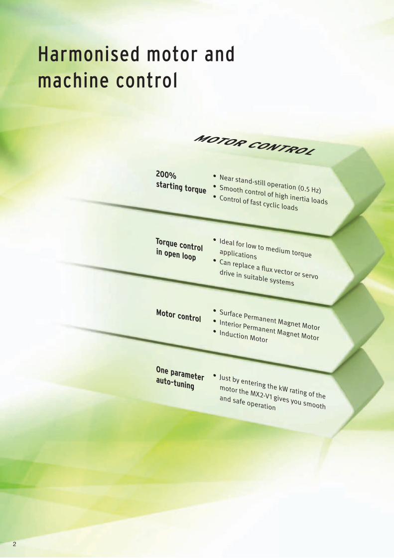
Motor control
One parameter auto-tuning
Torque control in open loop
200% starting torque
• Surface Permanent Magnet Motor• Interior Permanent Magnet Motor• Induction Motor
• Just by entering the kW rating of the motor the MX2-V1 gives you smooth and safe operation
• Ideal for low to medium torque applications• Can replace a flux vector or servo drive in suitable systems
• Near stand-still operation (0.5 Hz)• Smooth control of high inertia loads• Control of fast cyclic loads
MOTOR CONTROL
machine control
3
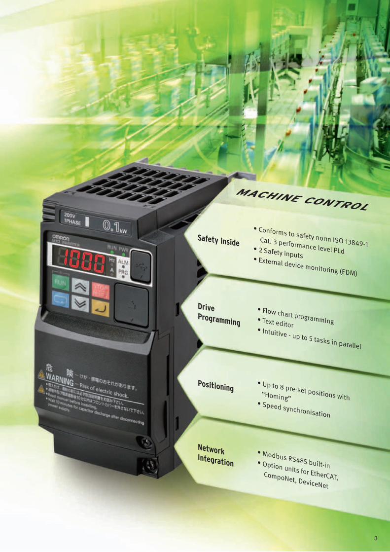
Positioning
Network Integration
Drive Programming
Safety inside
• Modbus RS485 built-in• Option units for EtherCAT, CompoNet, DeviceNet
• Conforms to safety norm ISO 13849-1 Cat. 3 performance level PLd• 2 Safety inputs• External device monitoring (EDM)
MACHINE CONTROL
• Up to 8 pre-set positions with “Homing”• Speed synchronisation
• Flow chart programming• Text editor• Intuitive - up to 5 tasks in parallel
4
0.5 3 6 10 20 30 40 50 600
100
200
Hz
Torq
ue (%
)
Amazing in Control
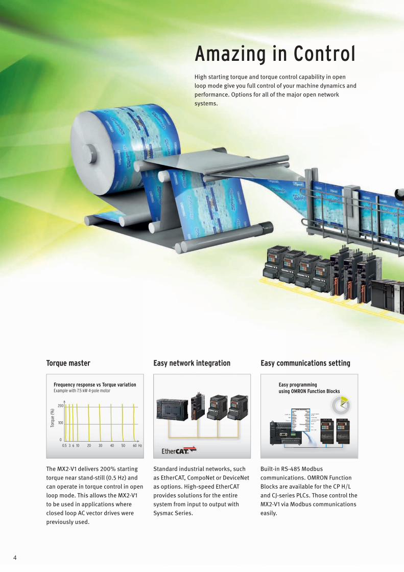
Easy communications settingEasy network integration Torque master
High starting torque and torque control capability in open loop mode give you full control of your machine dynamics and performance. Options for all of the major open network systems.
Frequency response vs Torque variationExample with 7.5 kW 4-pole motor
The MX2-V1 delivers 200% starting torque near stand-still (0.5 Hz) and can operate in torque control in open loop mode. This allows the MX2-V1 to be used in applications where closed loop AC vector drives were previously used.
Easy programming using OMRON Function Blocks
Standard industrial networks, such as EtherCAT, CompoNet or DeviceNet as options. High-speed EtherCAT provides solutions for the entire system from input to output with Sysmac Series.
Built-in RS-485 Modbus communications. OMRON Function Blocks are available for the CP H/L and CJ-series PLCs. Those control the MX2-V1 via Modbus communications easily.
5
Safety in Control
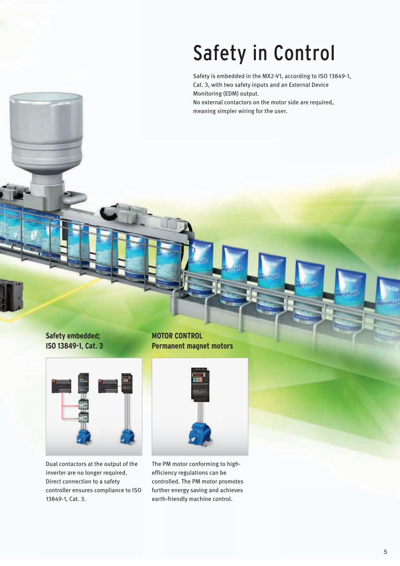
Safety embedded;ISO 13849-1, Cat. 3
MOTOR CONTROLPermanent magnet motors
Safety is embedded in the MX2-V1, according to ISO 13849-1, Cat. 3, with two safety inputs and an External Device Monitoring (EDM) output.No external contactors on the motor side are required, meaning simpler wiring for the user.
Dual contactors at the output of the inverter are no longer required.Direct connection to a safety controller ensures compliance to ISO 13849-1, Cat. 3.
The PM motor conforming to high-efficiency regulations can be controlled. The PM motor promotes further energy saving and achieves earth-friendly machine control.
6
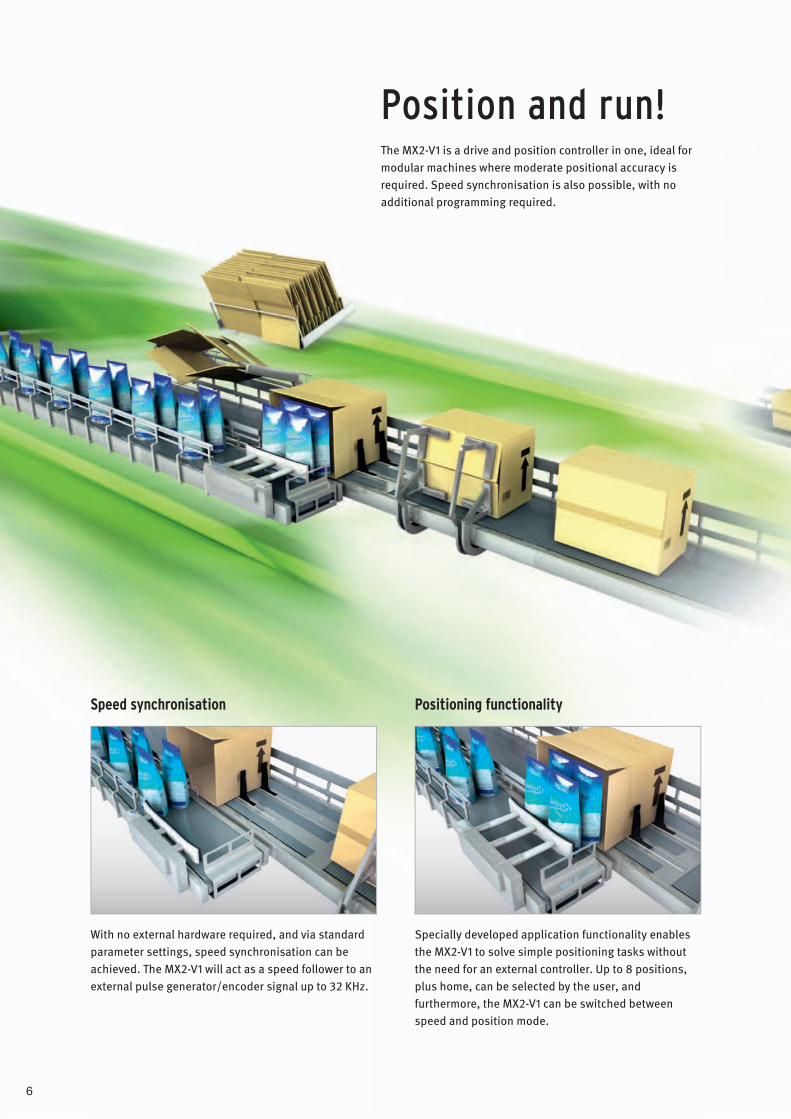
Position and run!
Speed synchronisation Positioning functionality
With no external hardware required, and via standard parameter settings, speed synchronisation can be achieved. The MX2-V1 will act as a speed follower to an external pulse generator/encoder signal up to 32 KHz.
Specially developed application functionality enables the MX2-V1 to solve simple positioning tasks without the need for an external controller. Up to 8 positions, plus home, can be selected by the user, and furthermore, the MX2-V1 can be switched between speed and position mode.
The MX2-V1 is a drive and position controller in one, ideal for modular machines where moderate positional accuracy is required. Speed synchronisation is also possible, with no additional programming required.
7
Position and run! Program and play!
Entry
End
Lbl0001
Lbl0002
Label
Label
If X(00)=1 GoTo
U(01):=20
Wait TD(0)=1Timer Off TD (0)
False
True
Next BlockNext Block
GoTo GoTo
Timer Set TD (0) U(01)
1
7
0
10
2
85
4
6 9
3
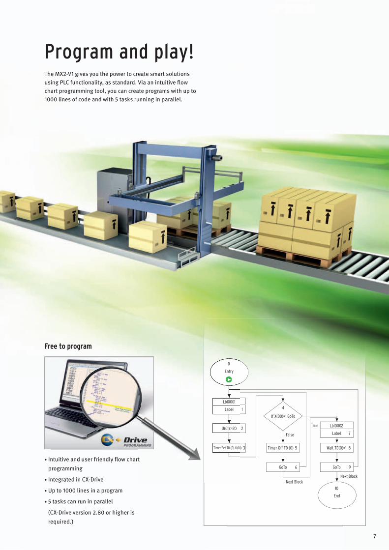
Free to program
The MX2-V1 gives you the power to create smart solutions using PLC functionality, as standard. Via an intuitive flow chart programming tool, you can create programs with up to 1000 lines of code and with 5 tasks running in parallel.
• Intuitive and user friendly flow chart programming
• Integrated in CX-Drive
• Up to 1000 lines in a program
• 5 tasks can run in parallel
(CX-Drive version 2.80 or higher is required.)

8
Multi-function Compact Inverter
MX2-Series V1 typeBorn to drive machines• Positioning functionality.• Fieldbus communications with optional unit
EtherCAT, CompoNet and DeviceNet• Drive Programming.• Current vector Control.• High Starting torque: 200% at 0.5 Hz.• Safety function * EN ISO 13849-1:2008 (Cat.3/PLd)
IEC 60204-1 Stop Category 0• Speed range up to 580 Hz.
* When optional DeviceNet communication unit or CompoNet communication unit is mounted onto the MX2-series V1 type, the inverter will not conform to the safety standards.
Performance SpecificationsInverter MX2-series V1 type3-phase 200 V Class
* The BRD usage is 10%.
Function name 3-phase 200 V
Model name (3G3MX2-) A2001-V1 A2002-V1 A2004-V1 A2007-V1 A2015-V1 A2022-V1 A2037-V1 A2055-V1 A2075-V1 A2110-V1 A2150-V1
Applicable motor capacity
kWCT 0.1 0.2 0.4 0.75 1.5 2.2 3.7 5.5 7.5 11 15
VT 0.2 0.4 0.75 1.1 2.2 3.0 5.5 7.5 11 15 18.5
HPCT 1/8 1/4 1/2 1 2 3 5 7 1/2 10 15 20
VT 1/4 1/2 1 1 1/2 3 4 7 1/2 10 15 20 25
Rated output capacity [kVA]
200 VCT 0.2 0.5 1.0 1.7 2.7 3.8 6.0 8.6 11.4 16.2 20.7
VT 0.4 0.6 1.2 2.0 3.3 4.1 6.7 10.3 13.8 19.3 23.9
240 VCT 0.3 0.6 1.2 2.0 3.3 4.5 7.2 10.3 13.7 19.5 24.9
VT 0.4 0.7 1.4 2.4 3.9 4.9 8.1 12.4 16.6 23.2 28.6
Rated input voltage 3-phase 200 V - 15% to 240 V + 10%, 50/60 Hz ± 5%
Rated input current [A]
CT 1.0 1.6 3.3 6.0 9.0 12.7 20.5 30.8 39.6 57.1 62.6
VT 1.2 1.9 3.9 7.2 10.8 13.9 23.0 37.0 48.0 68.0 72.0
Rated output voltage 3-phase 200 to 240 V (The output cannot exceed the incoming voltage).
Rated output current [A]
CT 1.0 1.6 3.0 5.0 8.0 11.0 17.5 25.0 33.0 47.0 60.0
VT 1.2 1.9 3.5 6.0 9.6 12.0 19.6 30.0 40.0 56.0 69.0
Short-time deceleration braking torque (%)(Discharge Resistor not connected)
50 50 50 50 50 20 20 20 20 10 10
BrakingResistor circuit *
Regenerative braking Built-in Braking Resistor circuit (separate Discharge Resistor)
Min. connectable resistance [Ω] 100 100 100 50 50 35 35 20 17 17 10
Weight [kg] 1.0 1.0 1.1 1.2 1.6 1.8 2.0 3.3 3.4 5.1 7.4
Dimensions (width × height) [mm] 68 × 128 108 × 128 140 ×
128 140 × 260 180 × 296
220 × 350
Dimensions (depth) [mm] 109 122.5 145.5 170.5 170.5 155 175

Multi-function Compact Inverter MX2-Series V1 type
9
3-phase 400 V Class
* The BRD usage is 10%.
1-phase 200 V Class
* The BRD usage is 10%.
Function name 3-phase 400 VModel name (3G3MX2-) A4004-V1 A4007-V1 A4015-V1 A4022-V1 A4030-V1 A4040-V1 A4055-V1 A4075-V1 A4110-V1 A4150-V1
Applicable motor capacity
kWCT 0.4 0.75 1.5 2.2 3.0 4.0 5.5 7.5 11 15
VT 0.75 1.5 2.2 3.0 4.0 5.5 7.5 11 15 18.5
HPCT 1/2 1 2 3 4 5 7 1/2 10 15 20
VT 1 2 3 4 5 7 1/2 10 15 20 25
Rated output capacity [kVA]
380 VCT 1.1 2.2 3.1 3.6 4.7 6.0 9.7 11.8 15.7 20.4
VT 1.3 2.6 3.5 4.5 5.7 7.3 11.5 15.1 20.4 25.0
480 VCT 1.4 2.8 3.9 4.5 5.9 7.6 12.3 14.9 19.9 25.7
VT 1.7 3.4 4.4 5.7 7.3 9.2 14.5 19.1 25.7 31.5
Rated input voltage 3-phase 380 V - 15% to 480 V + 10%, 50/60 Hz ± 5%
Rated input current [A]
CT 1.8 3.6 5.2 6.5 7.7 11.0 16.9 18.8 29.4 35.9
VT 2.1 4.3 5.9 8.1 9.4 13.3 20.0 24.0 38.0 44.0
Rated output voltage 3-phase 380 to 480 V (The output cannot exceed the incoming voltage).
Rated output current [A]
CT 1.8 3.4 4.8 5.5 7.2 9.2 14.8 18.0 24.0 31.0
VT 2.1 4.1 5.4 6.9 8.8 11.1 17.5 23.0 31.0 38.0
Short-time deceleration braking torque (%)(Discharge Resistor not connected)
50 50 50 20 20 20 20 20 10 10
BrakingResistor circuit *
Regenerative braking Built-in Braking Resistor circuit (separate Discharge Resistor)
Min. connectable resistance [Ω] 180 180 180 100 100 100 70 70 70 35
Weight [kg] 1.5 1.6 1.8 1.9 1.9 2.1 3.5 3.5 4.7 5.2
Dimensions (width × height) [mm] 108 × 128 140 ×
128 140 × 260 180 × 296
Dimensions (depth) [mm] 143.5 170.5 170.5 155 175
Function name 1-phase 200 VModel name (3G3MX2-) AB001-V1 AB002-V1 AB004-V1 AB007-V1 AB015-V1 AB022-V1
Applicable motor capacity
kWCT 0.1 0.2 0.4 0.75 1.5 2.2
VT 0.2 0.4 0.55 1.1 2.2 3.0
HPCT 1/8 1/4 1/2 1 2 3
VT 1/4 1/2 3/4 1 1/2 3 4
Rated output capacity [kVA]
200 VCT 0.2 0.5 1.0 1.7 2.7 3.8
VT 0.4 0.6 1.2 2.0 3.3 4.1
240 VCT 0.3 0.6 1.2 2.0 3.3 4.5
VT 0.4 0.7 1.4 2.4 3.9 4.9
Rated input voltage 1-phase 200 V - 15% to 240 V + 10%, 50/60 Hz ± 5%
Rated input current [A]
CT 1.3 3.0 6.3 11.5 16.8 22.0
VT 2.0 3.6 7.3 13.8 20.2 24.0
Rated output voltage 3-phase 200 to 240 V (The output cannot exceed the incoming voltage).
Rated output current [A]
CT 1.0 1.6 3.0 5.0 8.0 11.0
VT 1.2 1.9 3.5 6.0 9.6 12.0
Short-time deceleration braking torque (%)(Discharge Resistor not connected)
50 50 50 50 50 20
BrakingResistor circuit *
Regenerative braking Built-in Braking Resistor circuit (separate Discharge Resistor)
Min. connectable resistance [Ω] 100 100 100 50 50 35
Weight [kg] 1.0 1.0 1.1 1.6 1.8 1.8
Dimensions (width × height) [mm] 68 × 128 108 × 128
Dimensions (depth) [mm] 109 122.5 170.5
Multi-function Compact Inverter MX2-Series V1 type
10
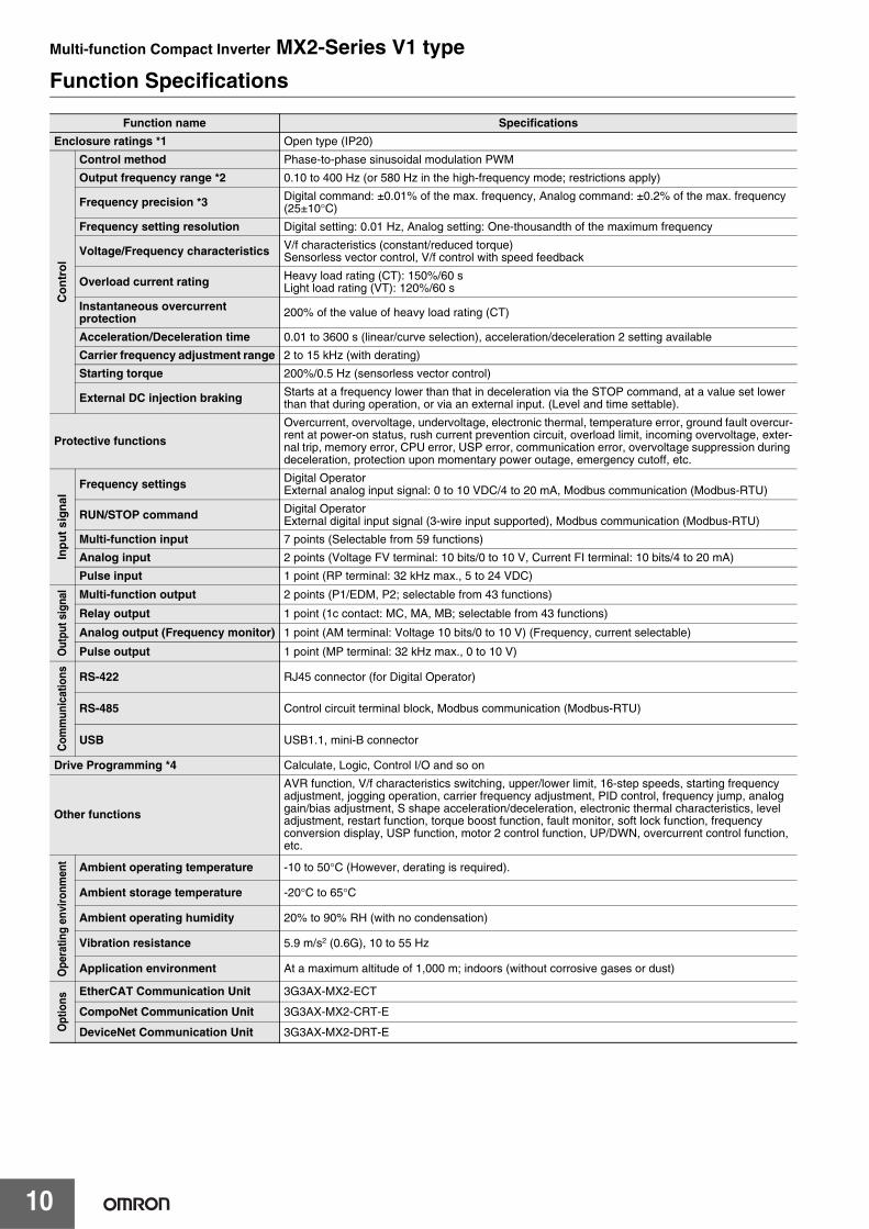
Function Specifications
Function name Specifications
Enclosure ratings *1 Open type (IP20)
Co
ntr
ol
Control method Phase-to-phase sinusoidal modulation PWM
Output frequency range *2 0.10 to 400 Hz (or 580 Hz in the high-frequency mode; restrictions apply)
Frequency precision *3 Digital command: ±0.01% of the max. frequency, Analog command: ±0.2% of the max. frequency (25±10°C)
Frequency setting resolution Digital setting: 0.01 Hz, Analog setting: One-thousandth of the maximum frequency
Voltage/Frequency characteristics V/f characteristics (constant/reduced torque)Sensorless vector control, V/f control with speed feedback
Overload current rating Heavy load rating (CT): 150%/60 sLight load rating (VT): 120%/60 s
Instantaneous overcurrent protection 200% of the value of heavy load rating (CT)
Acceleration/Deceleration time 0.01 to 3600 s (linear/curve selection), acceleration/deceleration 2 setting available
Carrier frequency adjustment range 2 to 15 kHz (with derating)
Starting torque 200%/0.5 Hz (sensorless vector control)
External DC injection braking Starts at a frequency lower than that in deceleration via the STOP command, at a value set lower than that during operation, or via an external input. (Level and time settable).
Protective functions
Overcurrent, overvoltage, undervoltage, electronic thermal, temperature error, ground fault overcur-rent at power-on status, rush current prevention circuit, overload limit, incoming overvoltage, exter-nal trip, memory error, CPU error, USP error, communication error, overvoltage suppression during deceleration, protection upon momentary power outage, emergency cutoff, etc.
Inp
ut
sig
nal
Frequency settings Digital Operator External analog input signal: 0 to 10 VDC/4 to 20 mA, Modbus communication (Modbus-RTU)
RUN/STOP command Digital OperatorExternal digital input signal (3-wire input supported), Modbus communication (Modbus-RTU)
Multi-function input 7 points (Selectable from 59 functions)
Analog input 2 points (Voltage FV terminal: 10 bits/0 to 10 V, Current FI terminal: 10 bits/4 to 20 mA)
Pulse input 1 point (RP terminal: 32 kHz max., 5 to 24 VDC)
Out
put s
igna
l Multi-function output 2 points (P1/EDM, P2; selectable from 43 functions)
Relay output 1 point (1c contact: MC, MA, MB; selectable from 43 functions)
Analog output (Frequency monitor) 1 point (AM terminal: Voltage 10 bits/0 to 10 V) (Frequency, current selectable)
Pulse output 1 point (MP terminal: 32 kHz max., 0 to 10 V)
Com
mun
icat
ions RS-422 RJ45 connector (for Digital Operator)
RS-485 Control circuit terminal block, Modbus communication (Modbus-RTU)
USB USB1.1, mini-B connector
Drive Programming *4 Calculate, Logic, Control I/O and so on
Other functions
AVR function, V/f characteristics switching, upper/lower limit, 16-step speeds, starting frequency adjustment, jogging operation, carrier frequency adjustment, PID control, frequency jump, analog gain/bias adjustment, S shape acceleration/deceleration, electronic thermal characteristics, level adjustment, restart function, torque boost function, fault monitor, soft lock function, frequency conversion display, USP function, motor 2 control function, UP/DWN, overcurrent control function, etc.
Ope
ratin
g en
viro
nmen
t Ambient operating temperature -10 to 50°C (However, derating is required).
Ambient storage temperature -20°C to 65°C
Ambient operating humidity 20% to 90% RH (with no condensation)
Vibration resistance 5.9 m/s2 (0.6G), 10 to 55 Hz
Application environment At a maximum altitude of 1,000 m; indoors (without corrosive gases or dust)
Opt
ions
EtherCAT Communication Unit 3G3AX-MX2-ECT
CompoNet Communication Unit 3G3AX-MX2-CRT-E
DeviceNet Communication Unit 3G3AX-MX2-DRT-E
Multi-function Compact Inverter MX2-Series V1 type
11
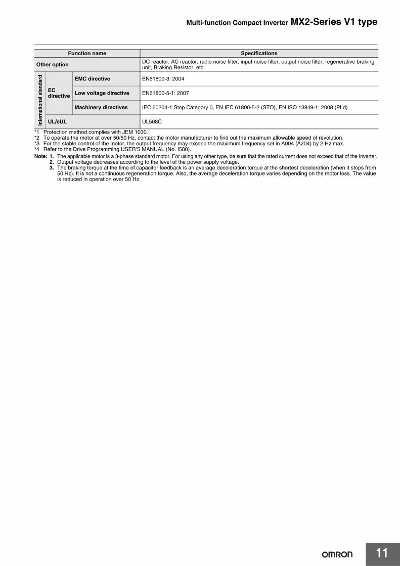
*1 Protection method complies with JEM 1030.*2 To operate the motor at over 50/60 Hz, contact the motor manufacturer to find out the maximum allowable speed of revolution.*3 For the stable control of the motor, the output frequency may exceed the maximum frequency set in A004 (A204) by 2 Hz max.*4 Refer to the Drive Programming USER'S MANUAL (No. I580).Note: 1. The applicable motor is a 3-phase standard motor. For using any other type, be sure that the rated current does not exceed that of the Inverter.
2. Output voltage decreases according to the level of the power supply voltage.3. The braking torque at the time of capacitor feedback is an average deceleration torque at the shortest deceleration (when it stops from
50 Hz). It is not a continuous regeneration torque. Also, the average deceleration torque varies depending on the motor loss. The value is reduced in operation over 50 Hz.
Other option DC reactor, AC reactor, radio noise filter, input noise filter, output noise filter, regenerative braking unit, Braking Resistor, etc.
Inte
rnat
iona
l sta
ndar
d
EC directive
EMC directive EN61800-3: 2004
Low voltage directive EN61800-5-1: 2007
Machinery directives IEC 60204-1 Stop Category 0, EN IEC 61800-5-2 (STO), EN ISO 13849-1: 2008 (PLd)
UL/cUL UL508C
Function name Specifications
Multi-function Compact Inverter MX2-Series V1 type
12
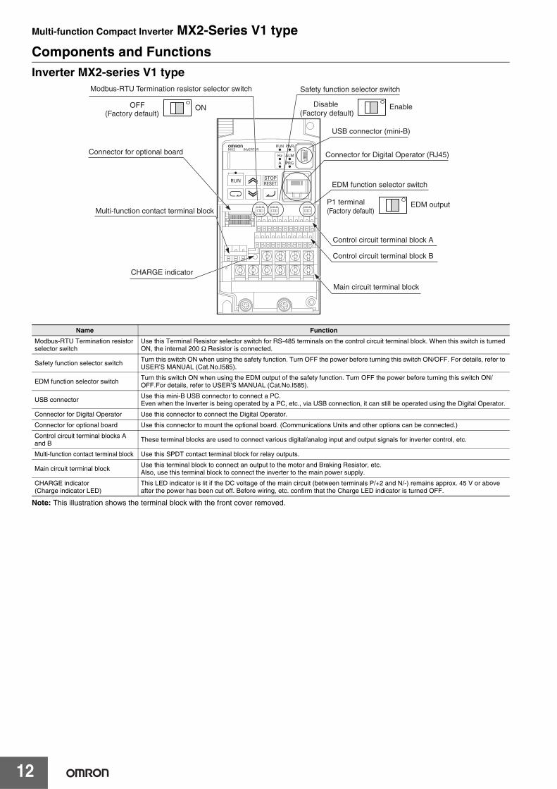
Components and Functions Inverter MX2-series V1 type
Note: This illustration shows the terminal block with the front cover removed.
Name Function
Modbus-RTU Termination resistor selector switch
Use this Terminal Resistor selector switch for RS-485 terminals on the control circuit terminal block. When this switch is turned ON, the internal 200 Ω Resistor is connected.
Safety function selector switch Turn this switch ON when using the safety function. Turn OFF the power before turning this switch ON/OFF. For details, refer to USER’S MANUAL (Cat.No.I585).
EDM function selector switch Turn this switch ON when using the EDM output of the safety function. Turn OFF the power before turning this switch ON/OFF.For details, refer to USER’S MANUAL (Cat.No.I585).
USB connector Use this mini-B USB connector to connect a PC.Even when the Inverter is being operated by a PC, etc., via USB connection, it can still be operated using the Digital Operator.
Connector for Digital Operator Use this connector to connect the Digital Operator.
Connector for optional board Use this connector to mount the optional board. (Communications Units and other options can be connected.)
Control circuit terminal blocks A and B These terminal blocks are used to connect various digital/analog input and output signals for inverter control, etc.
Multi-function contact terminal block Use this SPDT contact terminal block for relay outputs.
Main circuit terminal block Use this terminal block to connect an output to the motor and Braking Resistor, etc.Also, use this terminal block to connect the inverter to the main power supply.
CHARGE indicator (Charge indicator LED)
This LED indicator is lit if the DC voltage of the main circuit (between terminals P/+2 and N/-) remains approx. 45 V or above after the power has been cut off. Before wiring, etc. confirm that the Charge LED indicator is turned OFF.
Modbus-RTU Termination resistor selector switch Safety function selector switch
Connector for optional board
Multi-function contact terminal block
CHARGE indicator
Main circuit terminal block
OFF(Factory default)
ON
USB connector (mini-B)
Connector for Digital Operator (RJ45)
EDM function selector switch
Control circuit terminal block A
Control circuit terminal block B
Disable (Factory default)
Enable
P1 terminal (Factory default)
EDM output
Multi-function Compact Inverter MX2-Series V1 type
13
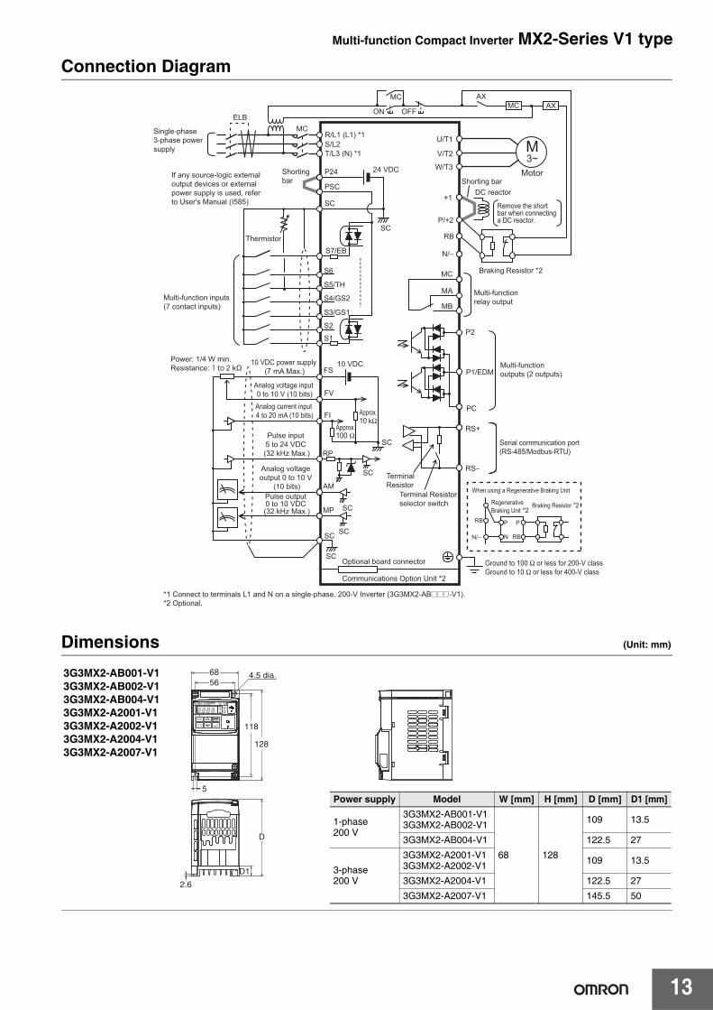
Connection Diagram
Dimensions (Unit: mm)
Single-phase3-phase power supply
Shorting bar Shorting bar
Motor
ELBMC
ON
R/L1 (L1) *1S/L2T/L3 (N) *1
24 VDC
MC
S7/EB
S5/TH
S4/GS2
S3/GS1
S2
S1
FS
FV
FI
RP
AM
MP
RS−
RS+
PC
P1/EDM
P2
MB
MA
N/−
SC
S6
P24
DC reactorPSC
SC
SC
If any source-logic external output devices or external power supply is used, refer to User's Manual (I585)
Multi-function outputs (2 outputs)
Multi-function relay output
Braking Resistor *2
*1 Connect to terminals L1 and N on a single-phase, 200-V Inverter (3G3MX2-AB@@@-V1).*2 Optional.
Power: 1/4 W min. Resistance: 1 to 2 kΩ
10 VDC power supply (7 mA Max.)
Analog voltage input 0 to 10 V (10 bits)
Analog voltage output 0 to 10 V
(10 bits)
Ground to 100 Ω or less for 200-V classGround to 10 Ω or less for 400-V class
Analog current input 4 to 20 mA (10 bits)
Pulse input 5 to 24 VDC (32 kHz Max.)
Pulse output 0 to 10 VDC (32 kHz Max.)
Serial communication port(RS-485/Modbus-RTU)
RB
P/+2
+1
W/T3
V/T2
U/T1 M3~
Remove the short bar when connecting a DC reactor.
RB
N/−
Regenerative Braking Unit *2
P
RB
Braking Resistor *2
When using a Regenerative Braking Unit
P
N
10 VDC
SC
SC
SC
SC
SC
Approx.100 Ω
Terminal Resistor
Terminal Resistor selector switch
Approx.10 kΩ
Thermistor
Optional board connector
Communications Option Unit *2
OFF
MC AXMC AX
Multi-function inputs (7 contact inputs)
8.8.8.8.
4.5 dia.
5
D1
2.6
6856
128
118
D
3G3MX2-AB001-V13G3MX2-AB002-V13G3MX2-AB004-V13G3MX2-A2001-V13G3MX2-A2002-V13G3MX2-A2004-V13G3MX2-A2007-V1
Power supply Model W [mm] H [mm] D [mm] D1 [mm]
1-phase 200 V
3G3MX2-AB001-V13G3MX2-AB002-V1
68 128
109 13.5
3G3MX2-AB004-V1 122.5 27
3-phase 200 V
3G3MX2-A2001-V13G3MX2-A2002-V1 109 13.5
3G3MX2-A2004-V1 122.5 27
3G3MX2-A2007-V1 145.5 50
Multi-function Compact Inverter MX2-Series V1 type
14
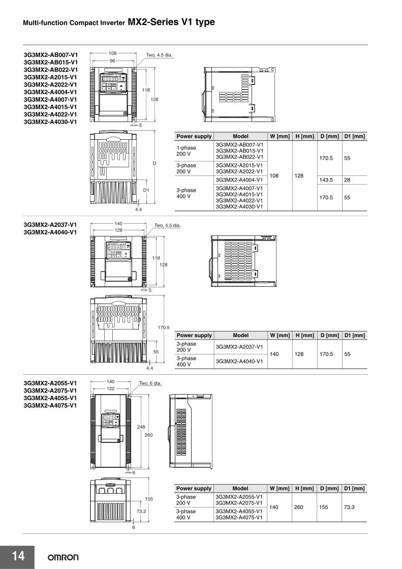
8.8.8.8.
5
4.4
Two, 4.5 dia.108
96
128
118
D1
D
3G3MX2-AB007-V13G3MX2-AB015-V13G3MX2-AB022-V13G3MX2-A2015-V13G3MX2-A2022-V13G3MX2-A4004-V13G3MX2-A4007-V13G3MX2-A4015-V13G3MX2-A4022-V13G3MX2-A4030-V1
Power supply Model W [mm] H [mm] D [mm] D1 [mm]
1-phase 200 V
3G3MX2-AB007-V13G3MX2-AB015-V13G3MX2-AB022-V1
108 128
170.5 553-phase 200 V
3G3MX2-A2015-V13G3MX2-A2022-V1
3-phase 400 V
3G3MX2-A4004-V1 143.5 28
3G3MX2-A4007-V13G3MX2-A4015-V13G3MX2-A4022-V13G3MX2-A4030-V1
170.5 55
8.8.8.8.
Two, 4.5 dia.
5
4.4
55
170.5
128118
140128
3G3MX2-A2037-V13G3MX2-A4040-V1
Power supply Model W [mm] H [mm] D [mm] D1 [mm]
3-phase 200 V 3G3MX2-A2037-V1
140 128 170.5 553-phase 400 V 3G3MX2-A4040-V1
8.8.8.8.
Two, 6 dia.
6
6
140
122
260
248
155
73.3
3G3MX2-A2055-V13G3MX2-A2075-V13G3MX2-A4055-V13G3MX2-A4075-V1
Power supply Model W [mm] H [mm] D [mm] D1 [mm]
3-phase 200 V
3G3MX2-A2055-V13G3MX2-A2075-V1
140 260 155 73.33-phase 400 V
3G3MX2-A4055-V13G3MX2-A4075-V1
Multi-function Compact Inverter MX2-Series V1 type
15
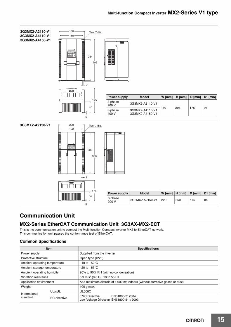
Communication UnitMX2-Series EtherCAT Communication Unit 3G3AX-MX2-ECTThis is the communication unit to connect the Multi-function Compact Inverter MX2 to EtherCAT network.This communication unit passed the conformance test of EtherCAT.
Common Specifications
Item Specifications
Power supply Supplied from the inverter
Protective structure Open type (IP20)
Ambient operating temperature −10 to +50°CAmbient storage temperature −20 to +65°CAmbient operating humidity 20% to 90% RH (with no condensation)
Vibration resistance 5.9 m/s2 (0.6 G), 10 to 55 Hz
Application environment At a maximum altitude of 1,000 m; indoors (without corrosive gases or dust)
Weight 100 g max.
International standard
UL/cUL UL508C
EC directive EMC Directive :EN61800-3: 2004Low Voltage Directive :EN61800-5-1: 2003
8.8.8.8.
Two, 7 dia.
7
5
180
160
296
284
175
97
3G3MX2-A2110-V13G3MX2-A4110-V13G3MX2-A4150-V1
Power supply Model W [mm] H [mm] D [mm] D1 [mm]
3-phase 200 V 3G3MX2-A2110-V1
180 296 175 973-phase 400 V
3G3MX2-A4110-V13G3MX2-A4150-V1
8.8.8.8.
Two, 7 dia.
7
5
220
192
350
336
175
84
3G3MX2-A2150-V1
Power supply Model W [mm] H [mm] D [mm] D1 [mm]
3-phase 200 V 3G3MX2-A2150-V1 220 350 175 84
Multi-function Compact Inverter MX2-Series V1 type
16
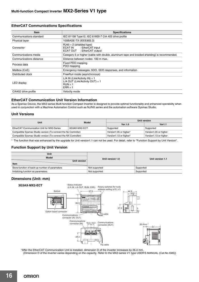
EtherCAT Communications Specifications
EtherCAT Communication Unit Version InformationAs a Sysmac Device, the MX2-series Multi-function Compact Inverter is designed to provide optimal functionality and enhanced operability when used in conjunction with a Machine Automation Control such as NJ/NX series and the automation software Sysmac Studio.
Unit Versions
* The function that was enhanced by the upgrade for Unit version1.1 can not be used. For detail, refer to "Function Support by Unit Version".
Function Support by Unit Version
Dimensions (Unit: mm)
*After the EtherCAT Communication Unit is installed, dimension D of the inverter increases by 26.4 mm.(Dimension D of the inverter varies depending on the capacity. Refer to the MX2-series V1 type USER'S MANUAL (Cat.No.I585))
Item Specifications
Communications standard IEC 61158 Type12, IEC 61800-7 CiA 402 drive profile
Physical layer 100BASE-TX (IEEE802.3)
ConnectorRJ45 × 2 (shielded type)ECAT IN : EtherCAT inputECAT OUT : EtherCAT output
Communications media Category 5 or higher (cable with double, aluminum tape and braided shielding) is recommended.
Communications distance Distance between nodes: 100 m max.
Process data Fixed PDO mappingPDO mapping
Mailbox (CoE) Emergency messages, SDO, SDO responses, and information
Distributed clock FreeRun mode (asynchronous)
LED display
L/A IN (Link/Activity IN) × 1L/A OUT (Link/Activity OUT) × 1RUN × 1ERR × 1
CiA402 drive profile Velocity mode
Unit ModelUnit version
Ver.1.0 Ver1.1
EtherCAT Communication Unit for MX2-Series 3G3AX-MX2-ECT Supported Supported
Compatible Sysmac Studio version (To connect the NJ Controller) Version1.05 or higher* Version1.05 or higher
Compatible Sysmac Studio version (To connect the NX Controller) Version1.13 or higher* Version1.13 or higher
Unit
Unit version 1.0 Unit version 1.1Model
Store-function of back-up number of parameters Not supported Supported
Initializing function as parameters. Not supported Supported
ItemUnit version
10.3 10.3
Status Indicator(L/A IN, L/A OUT, RUN, ERR)
Communications connector (IN) Communications
connector (OUT)
Rotary switches for node address setting (x10, x1)
26.4mm *
FG cable
FG cable
67.628.6
D *
44.9
28.2
60.0
27.9
Communications connector (IN, OUT)
Bottom
Option board connector
3G3AX-MX2-ECT
Multi-function Compact Inverter MX2-Series V1 type
17
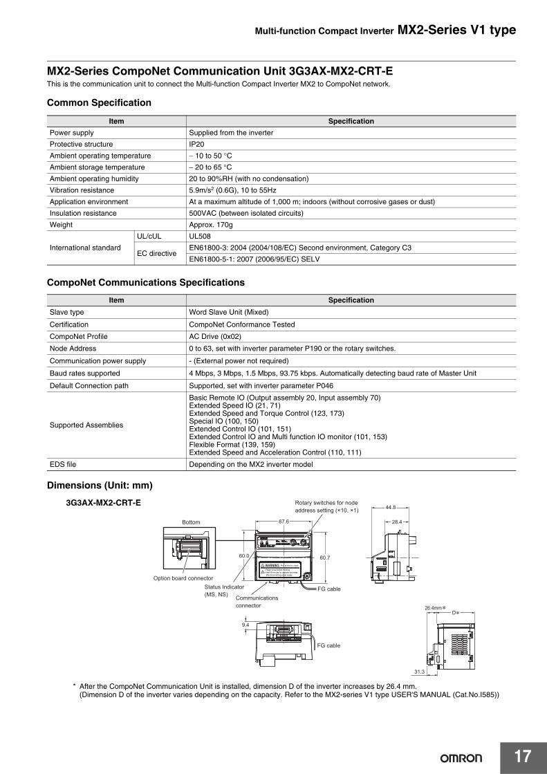
MX2-Series CompoNet Communication Unit 3G3AX-MX2-CRT-EThis is the communication unit to connect the Multi-function Compact Inverter MX2 to CompoNet network.
Common Specification
CompoNet Communications Specifications
Dimensions (Unit: mm)
* After the CompoNet Communication Unit is installed, dimension D of the inverter increases by 26.4 mm.(Dimension D of the inverter varies depending on the capacity. Refer to the MX2-series V1 type USER'S MANUAL (Cat.No.I585))
Item Specification
Power supply Supplied from the inverter
Protective structure IP20
Ambient operating temperature − 10 to 50 °C
Ambient storage temperature − 20 to 65 °C
Ambient operating humidity 20 to 90%RH (with no condensation)
Vibration resistance 5.9m/s2 (0.6G), 10 to 55Hz
Application environment At a maximum altitude of 1,000 m; indoors (without corrosive gases or dust)
Insulation resistance 500VAC (between isolated circuits)
Weight Approx. 170g
International standard
UL/cUL UL508
EC directiveEN61800-3: 2004 (2004/108/EC) Second environment, Category C3
EN61800-5-1: 2007 (2006/95/EC) SELV
Item Specification
Slave type Word Slave Unit (Mixed)
Certification CompoNet Conformance Tested
CompoNet Profile AC Drive (0x02)
Node Address 0 to 63, set with inverter parameter P190 or the rotary switches.
Communication power supply - (External power not required)
Baud rates supported 4 Mbps, 3 Mbps, 1.5 Mbps, 93.75 kbps. Automatically detecting baud rate of Master Unit
Default Connection path Supported, set with inverter parameter P046
Supported Assemblies
Basic Remote IO (Output assembly 20, Input assembly 70)Extended Speed IO (21, 71)Extended Speed and Torque Control (123, 173)Special IO (100, 150)Extended Control IO (101, 151)Extended Control IO and Multi function IO monitor (101, 153)Flexible Format (139, 159)Extended Speed and Acceleration Control (110, 111)
EDS file Depending on the MX2 inverter model
9.4
67.6 28.4
D26.4mm
60.760.0
44.8
31.3
FG cable
FG cable
Bottom
Option board connector
Rotary switches for nodeaddress setting (×10, ×1)
Communicationsconnector
Status Indicator(MS, NS)
3G3AX-MX2-CRT-E
Multi-function Compact Inverter MX2-Series V1 type
18
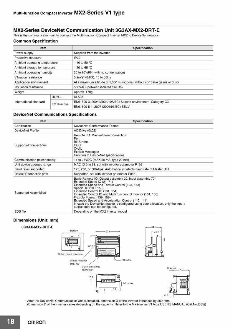
MX2-Series DeviceNet Communication Unit 3G3AX-MX2-DRT-EThis is the communication unit to connect the Multi-function Compact Inverter MX2 to DeviceNet network.
Common Specification
DeviceNet Communications Specifications
Dimensions (Unit: mm)
* After the DeviceNet Communication Unit is installed, dimension D of the inverter increases by 26.4 mm.(Dimension D of the inverter varies depending on the capacity. Refer to the MX2-series V1 type USER'S MANUAL (Cat.No.I585))
Item Specification
Power supply Supplied from the inverter
Protective structure IP20
Ambient operating temperature − 10 to 50 °C
Ambient storage temperature − 20 to 65 °C
Ambient operating humidity 20 to 90%RH (with no condensation)
Vibration resistance 5.9m/s2 (0.6G), 10 to 55Hz
Application environment At a maximum altitude of 1,000 m; indoors (without corrosive gases or dust)
Insulation resistance 500VAC (between isolated circuits)
Weight Approx. 170g
International standard
UL/cUL UL508
EC directiveEN61800-3: 2004 (2004/108/EC) Second environment, Category C3
EN61800-5-1: 2007 (2006/95/EC) SELV
Item Specification
Certification DeviceNet Conformance Tested
DeviceNet Profile AC Drive (0x02)
Supported connections
Remote I/O: Master-Slave connectionPollBit-StrobeCOSCyclicExplicit MessagesConform to DeviceNet specifications
Communication power supply 11 to 25VDC (MAX 50 mA, type 20 mA)
Unit device address range MAC ID 0 to 63, set with inverter parameter P192
Baud rates supported 125, 250, or 500kbps. Automatically detects baud rate of Master Unit.
Default Connection path Supported, set with inverter parameter P046
Supported Assemblies
Basic Remote IO (Output assembly 20, Input assembly 70)Extended Speed IO (21, 71)Extended Speed and Torque Control (123, 173)Special IO (100, 150)Extended Control IO (101, 151)Extended Control IO and Multi function IO monitor (101, 153)Flexible Format (139, 159)Extended Speed and Acceleration Control (110, 111)In case the DeviceNet master is configured using user allocation, only the input / output pairs can be configured.
EDS file Depending on the MX2 Inverter model
18.7
67.6 28.4
D*26.4mm*
60.0
44.8
31.3
Bottom
Option board connector
Status Indicator(MS, NS)
Communicationsconnector
FG cable
FG cable
3G3AX-MX2-DRT-E
Multi-function Compact Inverter MX2-Series V1 type
19
Options
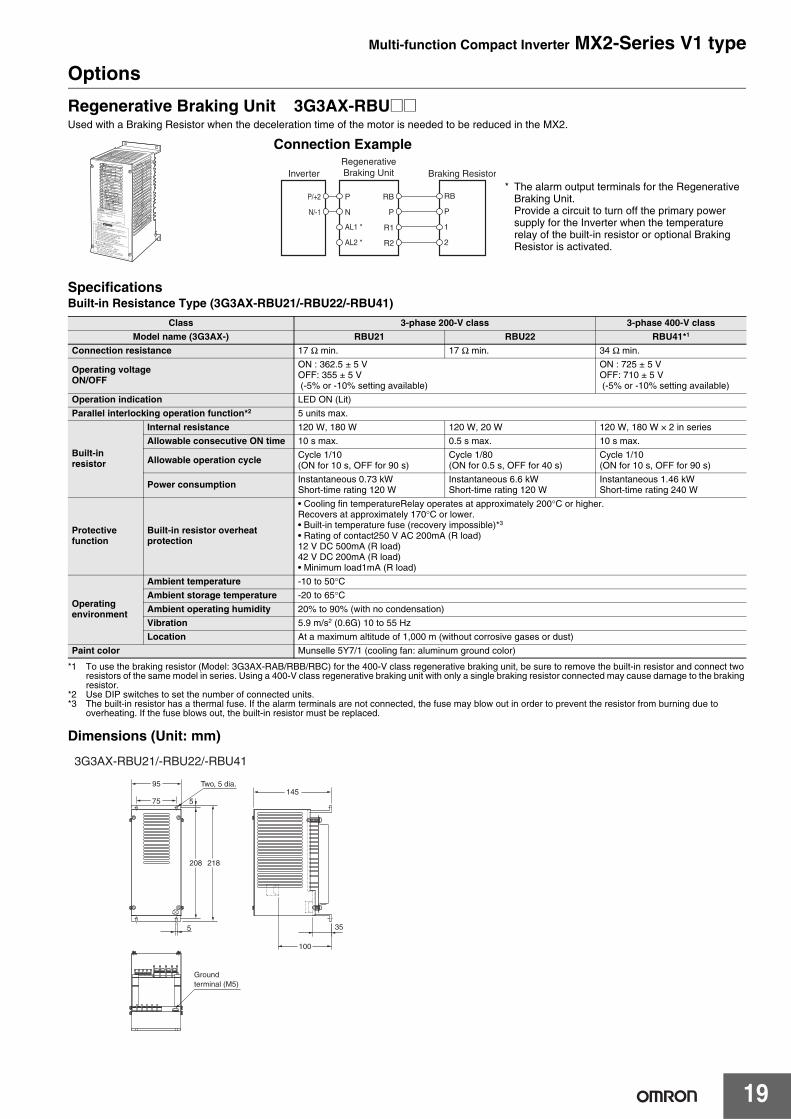
Regenerative Braking Unit 3G3AX-RBU@@Used with a Braking Resistor when the deceleration time of the motor is needed to be reduced in the MX2.
SpecificationsBuilt-in Resistance Type (3G3AX-RBU21/-RBU22/-RBU41)
*1 To use the braking resistor (Model: 3G3AX-RAB/RBB/RBC) for the 400-V class regenerative braking unit, be sure to remove the built-in resistor and connect two resistors of the same model in series. Using a 400-V class regenerative braking unit with only a single braking resistor connected may cause damage to the braking resistor.
*2 Use DIP switches to set the number of connected units.*3 The built-in resistor has a thermal fuse. If the alarm terminals are not connected, the fuse may blow out in order to prevent the resistor from burning due to
overheating. If the fuse blows out, the built-in resistor must be replaced.
Dimensions (Unit: mm)
Class 3-phase 200-V class 3-phase 400-V class
Model name (3G3AX-) RBU21 RBU22 RBU41*1
Connection resistance 17 Ω min. 17 Ω min. 34 Ω min.
Operating voltage ON/OFF
ON : 362.5 ± 5 VOFF: 355 ± 5 V (-5% or -10% setting available)
ON : 725 ± 5 VOFF: 710 ± 5 V (-5% or -10% setting available)
Operation indication LED ON (Lit)
Parallel interlocking operation function*2 5 units max.
Built-in resistor
Internal resistance 120 W, 180 W 120 W, 20 W 120 W, 180 W × 2 in series
Allowable consecutive ON time 10 s max. 0.5 s max. 10 s max.
Allowable operation cycle Cycle 1/10(ON for 10 s, OFF for 90 s)
Cycle 1/80(ON for 0.5 s, OFF for 40 s)
Cycle 1/10(ON for 10 s, OFF for 90 s)
Power consumption Instantaneous 0.73 kWShort-time rating 120 W
Instantaneous 6.6 kWShort-time rating 120 W
Instantaneous 1.46 kWShort-time rating 240 W
Protectivefunction
Built-in resistor overheatprotection
• Cooling fin temperatureRelay operates at approximately 200°C or higher.Recovers at approximately 170°C or lower.• Built-in temperature fuse (recovery impossible)*3
• Rating of contact250 V AC 200mA (R load)12 V DC 500mA (R load)42 V DC 200mA (R load)• Minimum load1mA (R load)
Operatingenvironment
Ambient temperature -10 to 50°CAmbient storage temperature -20 to 65°CAmbient operating humidity 20% to 90% (with no condensation)
Vibration 5.9 m/s2 (0.6G) 10 to 55 Hz
Location At a maximum altitude of 1,000 m (without corrosive gases or dust)
Paint color Munselle 5Y7/1 (cooling fan: aluminum ground color)
Connection Example
InverterRegenerativeBraking Unit Braking Resistor
RB
P
AL1 *
AL2 *
P
N
RB
P
1
2
R1
R2
P/+2
N/-1
* The alarm output terminals for the Regenerative Braking Unit.Provide a circuit to turn off the primary power supply for the Inverter when the temperature relay of the built-in resistor or optional Braking Resistor is activated.
Groundterminal (M5)
95
5
100
35
1455
208 218
75
Two, 5 dia.
3G3AX-RBU21/-RBU22/-RBU41
Multi-function Compact Inverter MX2-Series V1 type
20
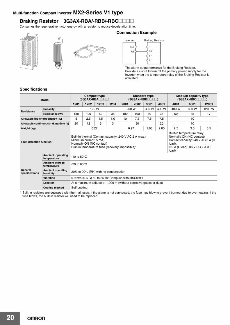
Braking Resistor 3G3AX-RBA/-RBB/-RBC@@@@Consumes the regenerative motor energy with a resistor to reduce deceleration time.
Specifications
* Built-in resistors are equipped with thermal fuses. If the alarm is not connected, the fuse may blow to prevent burnout due to overheating. If the fuse blows, the built-in resistor will need to be replaced.
ModelCompact type
(3G3AX-RBA@@@@)Standard type
(3G3AX-RBB@@@@)Medium capacity type(3G3AX-RBC@@@@)
1201 1202 1203 1204 2001 2002 3001 4001 4001 6001 12001
ResistanceCapacity 120 W 200 W 300 W 400 W 400 W 600 W 1200 W
Resistance (W) 180 100 50 35 180 100 50 35 50 35 17
Allowable brakingfrequency (%) 5 2.5 1.5 1.0 10 7.5 7.5 7.5 10
Allowable continuousbraking time (s) 20 12 5 3 30 20 10
Weight (kg) 0.27 0.97 1.68 2.85 2.5 3.6 6.5
Fault detection function
Built-in thermal (Contact capacity: 240 V AC 2 A max.)Minimum current: 5 mA, Normally ON (NC contact)Built-in temperature fuse (recovery impossible)*
Built-in temperature relay,Normally ON (NC contact)Contact capacity:240 V AC 3 A (R load),0.2 A (L load), 36 V DC 2 A (R load)
General specifications
Ambient operatingtemperature -10 to 50°C
Ambient storagetemperature -20 to 65°C
Ambient operatinghumidity 20% to 90% (RH) with no condensation
Vibration 5.9 m/s (0.6 G) 10 to 55 Hz Complies with JISC0911
Location At a maximum altitude of 1,000 m (without corrosive gases or dust)
Cooling method Self-cooling
Connection Example
Braking Resistor
P
RB
1 *
2 *
Inverter
P/+2
RB
* The alarm output terminals for the Braking Resistor.Provide a circuit to turn off the primary power supply for the Inverter when the temperature relay of the Braking Resistor is activated.
Multi-function Compact Inverter MX2-Series V1 type
21
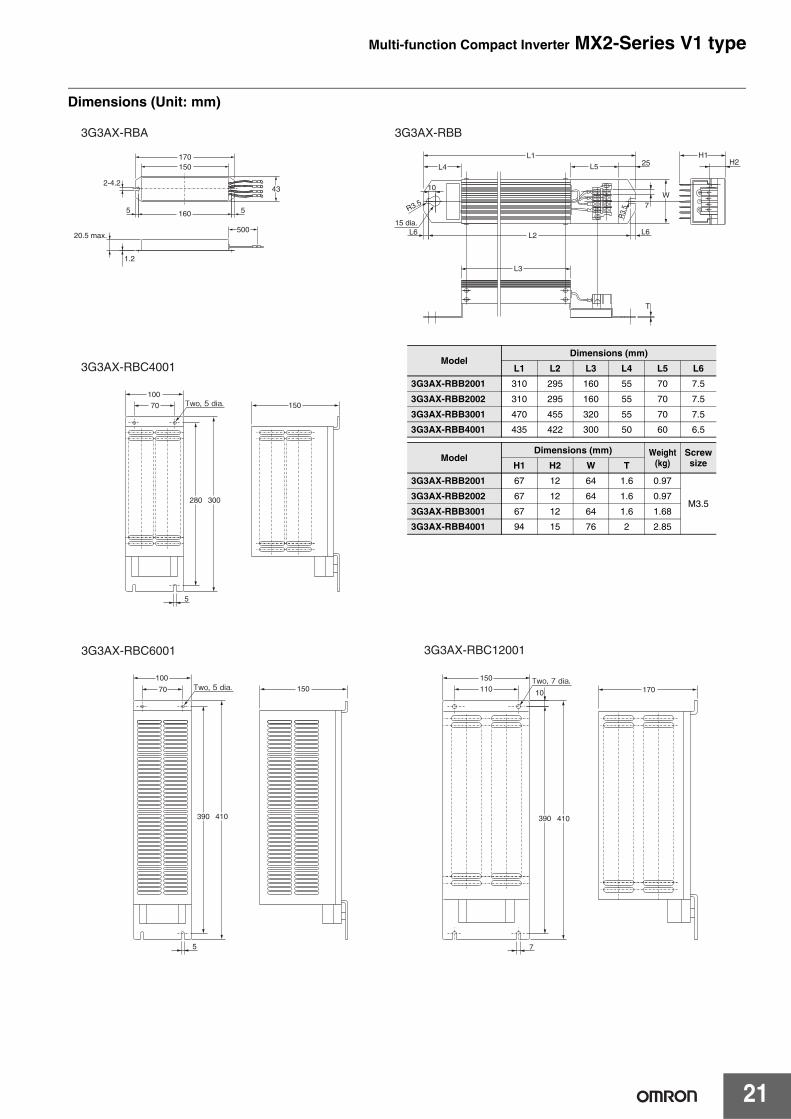
Dimensions (Unit: mm)
3G3AX-RBA 3G3AX-RBB
3G3AX-RBC4001
3G3AX-RBC120013G3AX-RBC6001
150
110
7
10 170
390 410390 410
100
70 150
150
280 300
5
5
100
70
500
1.2
20.5 max.
170
2-4.243
150
160 55
H1H2
L1
L4 L5 25
T
15 dia.
R3.5
10
L6
L3
L2 L6
R3.
5
W7
Two, 5 dia.
Two, 5 dia.Two, 7 dia.
ModelDimensions (mm)
L1 L2 L3 L4 L5 L6
3G3AX-RBB2001 310 295 160 55 70 7.5
3G3AX-RBB2002 310 295 160 55 70 7.5
3G3AX-RBB3001 470 455 320 55 70 7.5
3G3AX-RBB4001 435 422 300 50 60 6.5
ModelDimensions (mm) Weight
(kg)ScrewsizeH1 H2 W T
3G3AX-RBB2001 67 12 64 1.6 0.97
M3.53G3AX-RBB2002 67 12 64 1.6 0.97
3G3AX-RBB3001 67 12 64 1.6 1.68
3G3AX-RBB4001 94 15 76 2 2.85
Multi-function Compact Inverter MX2-Series V1 type
22
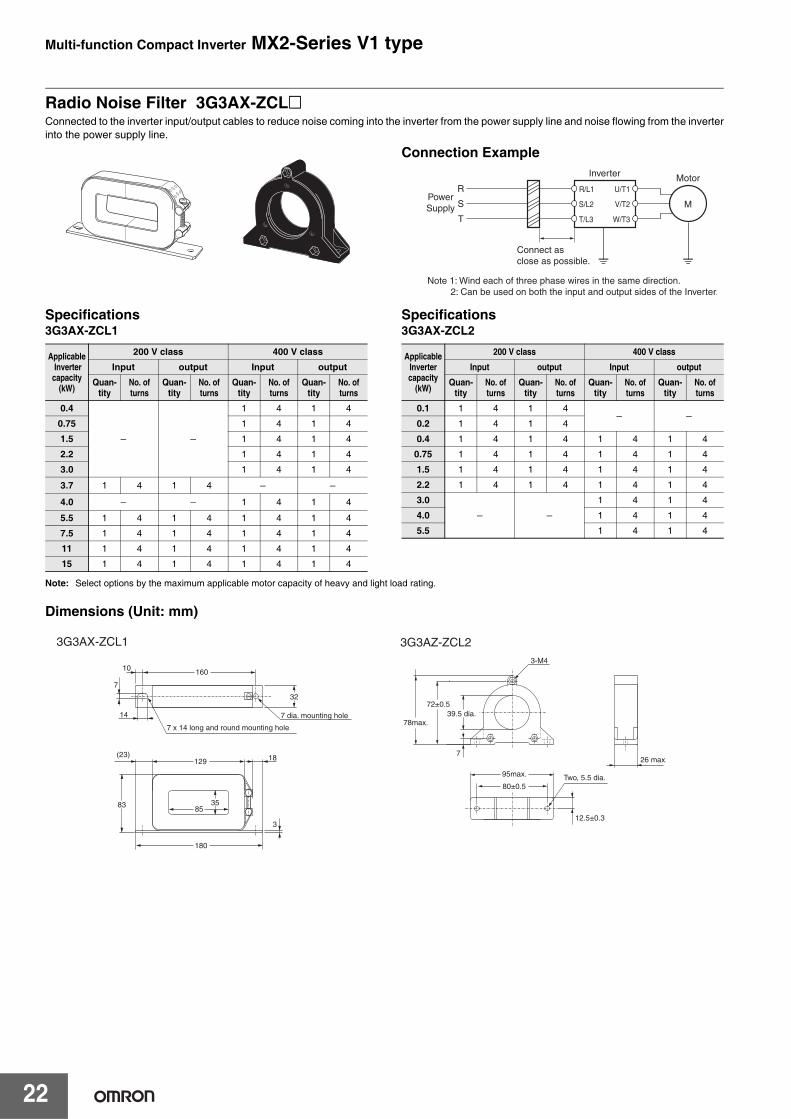
Radio Noise Filter 3G3AX-ZCL@Connected to the inverter input/output cables to reduce noise coming into the inverter from the power supply line and noise flowing from the inverterinto the power supply line.
Specifications3G3AX-ZCL1
Specifications3G3AX-ZCL2
Note: Select options by the maximum applicable motor capacity of heavy and light load rating.
Dimensions (Unit: mm)
Connection Example
R
S
T
M
Motor
PowerSupply
Connect asclose as possible.
Note 1: Wind each of three phase wires in the same direction. 2: Can be used on both the input and output sides of the Inverter.
Inverter
U/T1
V/T2
W/T3
S/L2
T/L3
R/L1
Applicable Invertercapacity
(kW)
200 V class 400 V class
Input output Input outputQuan-
tityNo. of turns
Quan-tity
No. of turns
Quan-tity
No. of turns
Quan-tity
No. of turns
0.4
− −
1 4 1 4
0.75 1 4 1 4
1.5 1 4 1 4
2.2 1 4 1 4
3.0 1 4 1 4
3.7 1 4 1 4 − −4.0 − − 1 4 1 4
5.5 1 4 1 4 1 4 1 4
7.5 1 4 1 4 1 4 1 4
11 1 4 1 4 1 4 1 4
15 1 4 1 4 1 4 1 4
ApplicableInvertercapacity
(kW)
200 V class 400 V class
Input output Input outputQuan-
tityNo. of turns
Quan-tity
No. of turns
Quan-tity
No. of turns
Quan-tity
No. of turns
0.1 1 4 1 4− −
0.2 1 4 1 4
0.4 1 4 1 4 1 4 1 4
0.75 1 4 1 4 1 4 1 4
1.5 1 4 1 4 1 4 1 4
2.2 1 4 1 4 1 4 1 4
3.0
− −1 4 1 4
4.0 1 4 1 4
5.5 1 4 1 4
160
3-M4
26 max.
95max. Two, 5.5 dia.80±0.5
18129
85
180
(23)
10
14
7 x 14 long and round mounting hole
7 dia. mounting hole
7
83 35
32
78max.
12.5±0.3
39.5 dia.
7
72±0.5
3
3G3AX-ZCL1 3G3AZ-ZCL2
Multi-function Compact Inverter MX2-Series V1 type
23
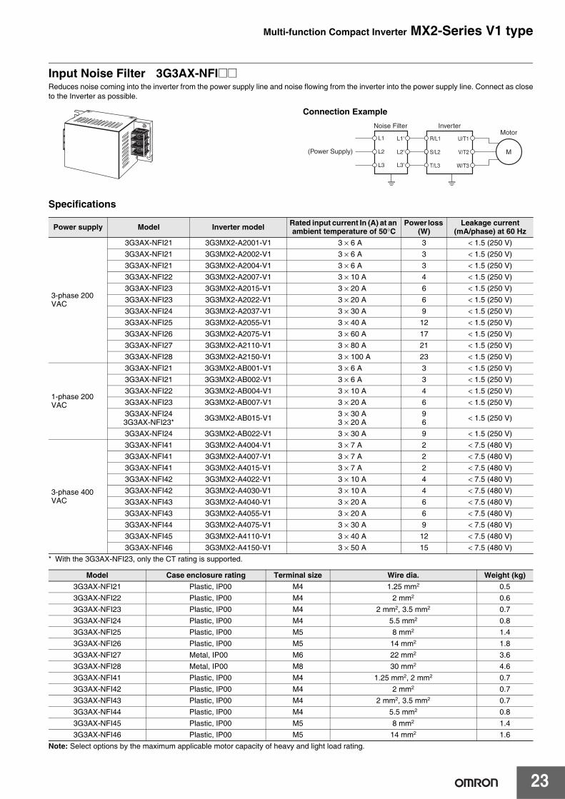
Input Noise Filter 3G3AX-NFI@@Reduces noise coming into the inverter from the power supply line and noise flowing from the inverter into the power supply line. Connect as closeto the Inverter as possible.
Specifications
* With the 3G3AX-NFI23, only the CT rating is supported.
Note: Select options by the maximum applicable motor capacity of heavy and light load rating.
Power supply Model Inverter model Rated input current In (A) at an ambient temperature of 50°C
Power loss (W)
Leakage current (mA/phase) at 60 Hz
3-phase 200 VAC
3G3AX-NFI21 3G3MX2-A2001-V1 3 × 6 A 3 < 1.5 (250 V)3G3AX-NFI21 3G3MX2-A2002-V1 3 × 6 A 3 < 1.5 (250 V)3G3AX-NFI21 3G3MX2-A2004-V1 3 × 6 A 3 < 1.5 (250 V)3G3AX-NFI22 3G3MX2-A2007-V1 3 × 10 A 4 < 1.5 (250 V)3G3AX-NFI23 3G3MX2-A2015-V1 3 × 20 A 6 < 1.5 (250 V)3G3AX-NFI23 3G3MX2-A2022-V1 3 × 20 A 6 < 1.5 (250 V)3G3AX-NFI24 3G3MX2-A2037-V1 3 × 30 A 9 < 1.5 (250 V)3G3AX-NFI25 3G3MX2-A2055-V1 3 × 40 A 12 < 1.5 (250 V)3G3AX-NFI26 3G3MX2-A2075-V1 3 × 60 A 17 < 1.5 (250 V)3G3AX-NFI27 3G3MX2-A2110-V1 3 × 80 A 21 < 1.5 (250 V)3G3AX-NFI28 3G3MX2-A2150-V1 3 × 100 A 23 < 1.5 (250 V)
1-phase 200 VAC
3G3AX-NFI21 3G3MX2-AB001-V1 3 × 6 A 3 < 1.5 (250 V)3G3AX-NFI21 3G3MX2-AB002-V1 3 × 6 A 3 < 1.5 (250 V)3G3AX-NFI22 3G3MX2-AB004-V1 3 × 10 A 4 < 1.5 (250 V)3G3AX-NFI23 3G3MX2-AB007-V1 3 × 20 A 6 < 1.5 (250 V)3G3AX-NFI24 3G3AX-NFI23* 3G3MX2-AB015-V1 3 × 30 A
3 × 20 A96 < 1.5 (250 V)
3G3AX-NFI24 3G3MX2-AB022-V1 3 × 30 A 9 < 1.5 (250 V)
3-phase 400 VAC
3G3AX-NFI41 3G3MX2-A4004-V1 3 × 7 A 2 < 7.5 (480 V)3G3AX-NFI41 3G3MX2-A4007-V1 3 × 7 A 2 < 7.5 (480 V)3G3AX-NFI41 3G3MX2-A4015-V1 3 × 7 A 2 < 7.5 (480 V)3G3AX-NFI42 3G3MX2-A4022-V1 3 × 10 A 4 < 7.5 (480 V)3G3AX-NFI42 3G3MX2-A4030-V1 3 × 10 A 4 < 7.5 (480 V)3G3AX-NFI43 3G3MX2-A4040-V1 3 × 20 A 6 < 7.5 (480 V)3G3AX-NFI43 3G3MX2-A4055-V1 3 × 20 A 6 < 7.5 (480 V)3G3AX-NFI44 3G3MX2-A4075-V1 3 × 30 A 9 < 7.5 (480 V)3G3AX-NFI45 3G3MX2-A4110-V1 3 × 40 A 12 < 7.5 (480 V)3G3AX-NFI46 3G3MX2-A4150-V1 3 × 50 A 15 < 7.5 (480 V)
Model Case enclosure rating Terminal size Wire dia. Weight (kg)3G3AX-NFI21 Plastic, IP00 M4 1.25 mm2 0.53G3AX-NFI22 Plastic, IP00 M4 2 mm2 0.63G3AX-NFI23 Plastic, IP00 M4 2 mm2, 3.5 mm2 0.73G3AX-NFI24 Plastic, IP00 M4 5.5 mm2 0.83G3AX-NFI25 Plastic, IP00 M5 8 mm2 1.43G3AX-NFI26 Plastic, IP00 M5 14 mm2 1.83G3AX-NFI27 Metal, IP00 M6 22 mm2 3.63G3AX-NFI28 Metal, IP00 M8 30 mm2 4.63G3AX-NFI41 Plastic, IP00 M4 1.25 mm2, 2 mm2 0.73G3AX-NFI42 Plastic, IP00 M4 2 mm2 0.73G3AX-NFI43 Plastic, IP00 M4 2 mm2, 3.5 mm2 0.73G3AX-NFI44 Plastic, IP00 M4 5.5 mm2 0.83G3AX-NFI45 Plastic, IP00 M5 8 mm2 1.43G3AX-NFI46 Plastic, IP00 M5 14 mm2 1.6
Connection Example
L1'
L2'
L3'
Noise Filter Inverter
L1
L2
L3
M(Power Supply)
MotorU/T1
V/T2
W/T3
S/L2
T/L3
R/L1
Multi-function Compact Inverter MX2-Series V1 type
24
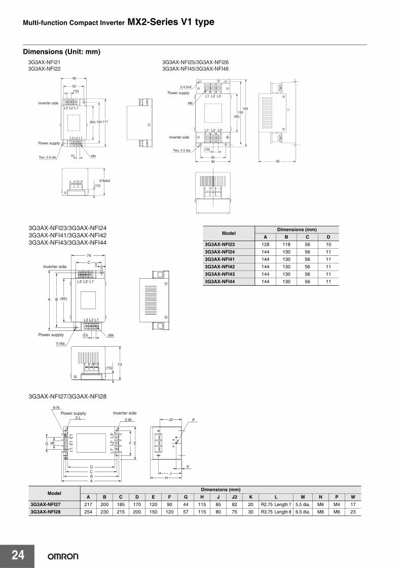
Dimensions (Unit: mm)
Inverter side
66
52(10)
L3' L2' L1'
L3 L2 L1
(84) 100 117
Two, 5.0 dia. 10 M4
67MAX(15)
Power supply
Inverter side
6590
(16)
L1' L2' L3'
L1 L2 L3
155165
Two, 4.5 dia.
M6
(95)
Power supply
2-4.5×6
95
3G3AX-NFI213G3AX-NFI22
3G3AX-NFI25/3G3AX-NFI263G3AX-NFI45/3G3AX-NFI46
Inverter side
Power supply
L3' L2' L1'
L3 L2 L1
(95)
74
(D)
5
M4
(15)73
C
BA
5 dia.
3G3AX-NFI23/3G3AX-NFI243G3AX-NFI41/3G3AX-NFI423G3AX-NFI43/3G3AX-NFI44
ModelDimensions (mm)
A B C D3G3AX-NFI23 128 118 56 10
3G3AX-NFI24 144 130 56 11
3G3AX-NFI41 144 130 56 11
3G3AX-NFI42 144 130 56 11
3G3AX-NFI43 144 130 56 11
3G3AX-NFI44 144 130 56 11
ININ
Inverter side
A
6-N
G
Power supply
L1'
L2'
L3'L3 L2 L1
BCD
F EW
2-L 2-M
JH
J2
K
P
3G3AX-NFI27/3G3AX-NFI28
ModelDimensions (mm)
A B C D E F G H J J2 K L M N P W3G3AX-NFI27 217 200 185 170 120 90 44 115 85 82 20 R2.75 Length 7 5.5 dia. M6 M4 17
3G3AX-NFI28 254 230 215 200 150 120 57 115 80 75 30 R3.75 Length 8 6.5 dia. M8 M6 23

Multi-function Compact Inverter MX2-Series V1 type
25
Output Noise Filter 3G3AX-NFO@@Reduces noise generated by the Inverter. Connect as close to the Inverter as possible.
Specifications
Note: Select options by the maximum applicable motor capacity of heavy and light load rating.
Dimensions (Unit: mm)
Power supply ModelRated
current (A)
Inverter modelWeight
(kg)3-phase AC 200 V class
1-phase AC 200 V class
3-phase AC 400 V class
3-phase, 3-wireRated voltage500 VAC
3G3AX-NFO01 6 3G3MX2-A2001-V1/-A2002-V1/-A2004-V1
3G3MX2-AB001-V1/-AB002-V1/-AB004-V1
3G3MX2-A4004-V1/-A4007-V1 0.7
3G3AX-NFO02 12 3G3MX2-A2007-V1/-A2015-V1
3G3MX2-AB007-V1/-AB015-V1
3G3MX2-A4015-V1/-A4022-V1/-A4030-V1 0.9
3G3AX-NFO03 25 3G3MX2-A2022-V1/-A2037-V1 3G3MX2-AB022-V1 3G3MX2-A4040-V1
/-A4055-V1/-A4075-V1 2.1
3G3AX-NFO04 50 3G3MX2-A2055-V1/-A2075-V1 − 3G3MX2-A4110-V1
/-A4150-V1 3.7
3G3AX-NFO05 75 3G3MX2-A2110-V1/-A2150-V1 − − 5.7
Model A B C D E F G H J K L
3G3AX-NFO01 140 125 110 156 70 95 50 R: 2.25mmLength: 6mm 4.5 mm dia. M4 -
3G3AX-NFO02 160 145 130 176 80 110 70 R: 2.75mmLength: 7mm 5.5 mm dia. M4 -
3G3AX-NFO03 112 80 154 160 145 130 120 − 6.5 mm dia. M4 -
3G3AX-NFO04 162 100 210 200 180 160 150 − 6.5 mm dia. M5 M5
3G3AX-NFO05 182 100 230 220 200 180 170 − 6.5 mm dia. M6 M6
Connection Example
4
5
6
Noise Filter
1
2
3
M(Power supply)
MotorInverter
U/T1
V/T2
W/T3
S/L2
T/L3
R/L1
3G3AX-NFO013G3AX-NFO02
3G3AX-NFO03/3G3AX-NFO04/3G3AX-NFO05
DEF
K×6
K×6
J×2H
H
J×4
LDABC
BACE F
GG
Multi-function Compact Inverter MX2-Series V1 type
26
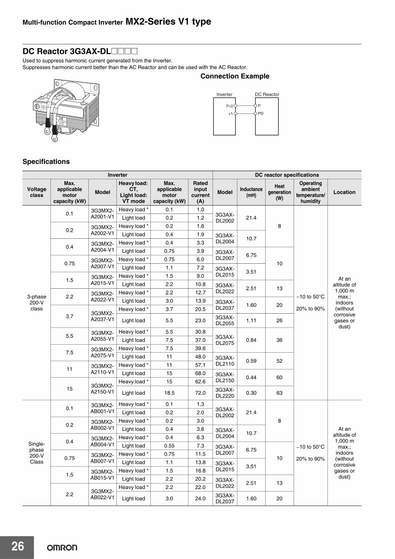
DC Reactor 3G3AX-DL@@@@Used to suppress harmonic current generated from the Inverter.Suppresses harmonic current better than the AC Reactor and can be used with the AC Reactor.
Specifications
Inverter DC reactor specifications
Voltage class
Max. applicable
motor capacity (kW)
Model
Heavy load: CT,
Light load:VT mode
Max. applicable
motor capacity (kW)
Rated input
current (A)
Model Inductance (mH)
Heat generation
(W)
Operating ambient
temperature/humidity
Location
3-phase 200-V class
0.1 3G3MX2-A2001-V1
Heavy load * 0.1 1.03G3AX-DL2002 21.4
8
−10 to 50°C
20% to 90%
At an altitude of 1,000 m
max.;indoors(without
corrosive gases or
dust)
Light load 0.2 1.2
0.2 3G3MX2-A2002-V1
Heavy load * 0.2 1.6
Light load 0.4 1.9 3G3AX-DL2004 10.7
0.4 3G3MX2-A2004-V1
Heavy load * 0.4 3.3
Light load 0.75 3.9 3G3AX-DL2007 6.75
100.75 3G3MX2-A2007-V1
Heavy load * 0.75 6.0
Light load 1.1 7.2 3G3AX-DL2015 3.51
1.5 3G3MX2-A2015-V1
Heavy load * 1.5 9.0
Light load 2.2 10.8 3G3AX-DL2022 2.51 13
2.2 3G3MX2-A2022-V1
Heavy load * 2.2 12.7
Light load 3.0 13.9 3G3AX-DL2037 1.60 20
3.7 3G3MX2-A2037-V1
Heavy load * 3.7 20.5
Light load 5.5 23.0 3G3AX-DL2055 1.11 26
5.5 3G3MX2-A2055-V1
Heavy load * 5.5 30.83G3AX-DL2075 0.84 36Light load 7.5 37.0
7.5 3G3MX2-A2075-V1
Heavy load * 7.5 39.6
Light load 11 48.0 3G3AX-DL2110 0.59 52
11 3G3MX2-A2110-V1
Heavy load * 11 57.1
Light load 15 68.0 3G3AX-DL2150 0.44 60
15 3G3MX2-A2150-V1
Heavy load * 15 62.6
Light load 18.5 72.0 3G3AX-DL2220 0.30 63
Single-phase 200-V Class
0.1 3G3MX2-AB001-V1
Heavy load * 0.1 1.33G3AX-DL2002 21.4
8
−10 to 50°C
20% to 90%
At an altitude of 1,000 m
max.;indoors(without
corrosive gases or
dust)
Light load 0.2 2.0
0.2 3G3MX2-AB002-V1
Heavy load * 0.2 3.0
Light load 0.4 3.6 3G3AX-DL2004 10.7
0.4 3G3MX2-AB004-V1
Heavy load * 0.4 6.3
Light load 0.55 7.3 3G3AX-DL2007 6.75
100.75 3G3MX2-AB007-V1
Heavy load * 0.75 11.5
Light load 1.1 13.8 3G3AX-DL2015 3.51
1.5 3G3MX2-AB015-V1
Heavy load * 1.5 16.8
Light load 2.2 20.2 3G3AX-DL2022 2.51 13
2.2 3G3MX2-AB022-V1
Heavy load * 2.2 22.0
Light load 3.0 24.0 3G3AX-DL2037 1.60 20
Connection Example
DC Reactor
P
PD
Inverter
P/+2
+1
Multi-function Compact Inverter MX2-Series V1 type
27
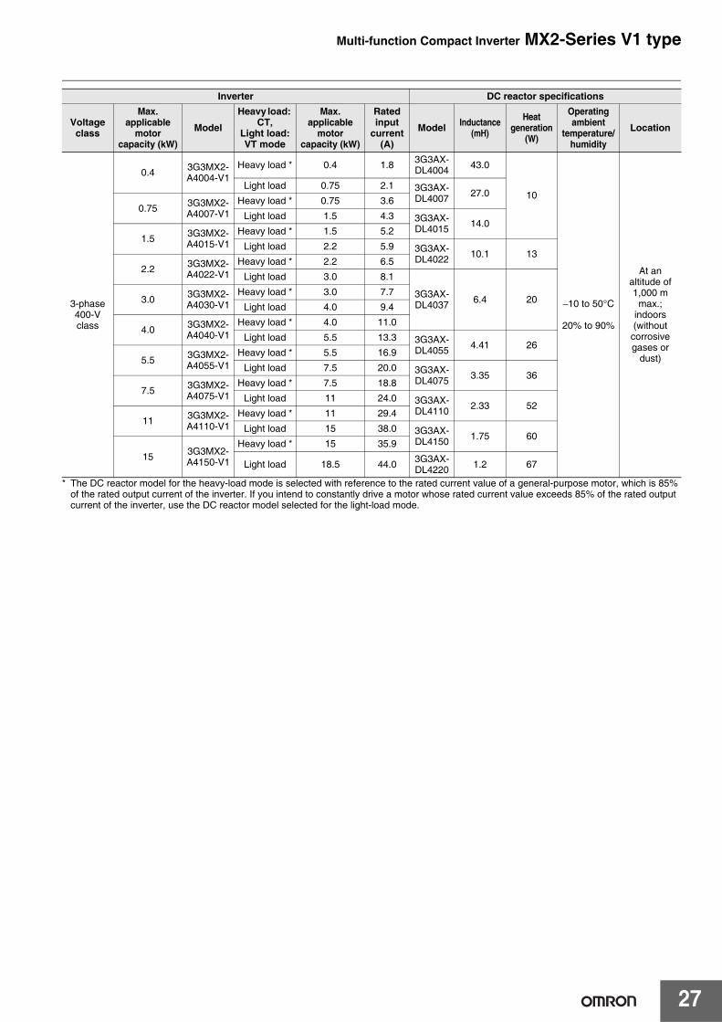
* The DC reactor model for the heavy-load mode is selected with reference to the rated current value of a general-purpose motor, which is 85% of the rated output current of the inverter. If you intend to constantly drive a motor whose rated current value exceeds 85% of the rated output current of the inverter, use the DC reactor model selected for the light-load mode.
3-phase 400-V class
0.4 3G3MX2-A4004-V1
Heavy load * 0.4 1.8 3G3AX-DL4004 43.0
10
−10 to 50°C
20% to 90%
At an altitude of 1,000 m
max.;indoors(without
corrosive gases or
dust)
Light load 0.75 2.1 3G3AX-DL4007 27.0
0.75 3G3MX2-A4007-V1
Heavy load * 0.75 3.6
Light load 1.5 4.3 3G3AX-DL4015 14.0
1.5 3G3MX2-A4015-V1
Heavy load * 1.5 5.2
Light load 2.2 5.9 3G3AX-DL4022 10.1 13
2.2 3G3MX2-A4022-V1
Heavy load * 2.2 6.5
Light load 3.0 8.1
3G3AX-DL4037 6.4 203.0 3G3MX2-
A4030-V1Heavy load * 3.0 7.7
Light load 4.0 9.4
4.0 3G3MX2-A4040-V1
Heavy load * 4.0 11.0
Light load 5.5 13.3 3G3AX-DL4055 4.41 26
5.5 3G3MX2-A4055-V1
Heavy load * 5.5 16.9
Light load 7.5 20.0 3G3AX-DL4075 3.35 36
7.5 3G3MX2-A4075-V1
Heavy load * 7.5 18.8
Light load 11 24.0 3G3AX-DL4110 2.33 52
11 3G3MX2-A4110-V1
Heavy load * 11 29.4
Light load 15 38.0 3G3AX-DL4150 1.75 60
15 3G3MX2-A4150-V1
Heavy load * 15 35.9
Light load 18.5 44.0 3G3AX-DL4220 1.2 67
Inverter DC reactor specifications
Voltage class
Max. applicable
motor capacity (kW)
Model
Heavy load: CT,
Light load:VT mode
Max. applicable
motor capacity (kW)
Rated input
current (A)
Model Inductance (mH)
Heat generation
(W)
Operating ambient
temperature/humidity
Location
Multi-function Compact Inverter MX2-Series V1 type
28
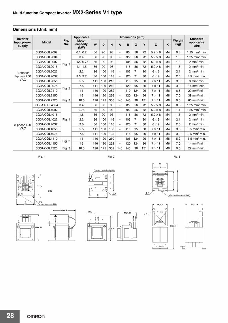
Dimensions (Unit: mm)
Inverter input power
supplyModel Fig.
No.
ApplicableMotor
capacity (kW)
Dimensions (mm)Weight
(kg)
Standard applicable
wireW D H A B X Y C K
3-phase/1-phase 200
VAC
3G3AX-DL2002
Fig. 1
0.1, 0.2 66 90 98 − 85 56 72 5.2 × 8 M4 0.8 1.25 mm2 min.
3G3AX-DL2004 0.4 66 90 98 − 95 56 72 5.2 × 8 M4 1.0 1.25 mm2 min.
3G3AX-DL2007 0.55, 0.75 66 90 98 − 105 56 72 5.2 × 8 M4 1.3 2 mm2 min.
3G3AX-DL2015 1.1, 1.5 66 90 98 − 115 56 72 5.2 × 8 M4 1.6 2 mm2 min.
3G3AX-DL2022 2.2 86 100 116 − 105 71 80 6 × 9 M4 2.1 2 mm2 min.
3G3AX-DL2037 3.0, 3.7 86 100 118 − 120 71 80 6 × 9 M4 2.6 3.5 mm2 min.
3G3AX-DL2055
Fig. 2
5.5 111 100 210 − 110 95 80 7 × 11 M5 3.6 8 mm2 min.
3G3AX-DL2075 7.5 111 100 212 − 120 95 80 7 × 11 M6 3.9 14 mm2 min.
3G3AX-DL2110 11 146 120 252 − 110 124 96 7 × 11 M6 6.5 22 mm2 min.
3G3AX-DL2150 15 146 120 256 − 120 124 96 7 × 11 M8 7.0 38 mm2 min.
3G3AX-DL2220 Fig. 3 18.5 120 175 356 140 145 98 151 7 × 11 M8 9.0 60 mm2 min.
3-phase 400 VAC
3G3AX- DL4004
Fig. 1
0.4 66 90 98 − 85 56 72 5.2 × 8 M4 0.8 1.25 mm2 min.
3G3AX-DL4007 0.75 66 90 98 − 95 56 72 5.2 × 8 M4 1.1 1.25 mm2 min.
3G3AX-DL4015 1.5 66 90 98 − 115 56 72 5.2 × 8 M4 1.6 2 mm2 min.
3G3AX-DL4022 2.2 86 100 116 − 105 71 80 6 × 9 M4 2.1 2 mm2 min.
3G3AX-DL4037 3.0 86 100 116 − 120 71 80 6 × 9 M4 2.6 2 mm2 min.
3G3AX-DL4055 5.5 111 100 138 − 110 95 80 7 × 11 M4 3.6 3.5 mm2 min.
3G3AX-DL4075 7.5 111 100 138 − 115 95 80 7 × 11 M4 3.9 3.5 mm2 min.
3G3AX-DL4110Fig. 2
11 146 120 250 − 105 124 96 7 × 11 M5 5.2 5.5 mm2 min.
3G3AX-DL4150 15 146 120 252 − 120 124 96 7 × 11 M6 7.0 14 mm2 min.
3G3AX-DL4220 Fig. 3 18.5 120 175 352 140 145 98 151 7 × 11 M6 9.5 22 mm2 min.
Fig. 1 Fig. 2 Fig. 3
Y
Y D
Max. H Max. H
D
2-K
W
4-C
Max.A Max. B
Max. H
2-K
X
Y D
Max. BMax. B2-K
WX
Ground terminal (M5)
Ground terminal (M6)4-C
X 4-CGround terminal (M4)W
Multi-function Compact Inverter MX2-Series V1 type
29
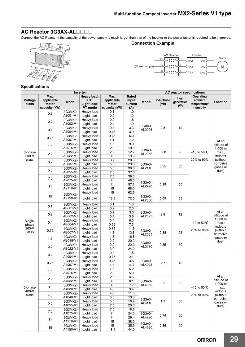
AC Reactor 3G3AX-AL@@@@Connect the AC Reactor if the capacity of the power supply is much larger than that of the Inverter or the power factor is required to be improved.
SpecificationsInverter AC reactor specifications
Voltage class
Max. applicable
motor capacity (kW)
Model
Heavy load: CT,
Light load:VT mode
Max. applicable
motor capacity (kW)
Rated input
current (A)
Model Inductance (mH)
Heat generation
(W)
Operating ambient
temperature/humidity
Location
3-phase 200-V class
0.1 3G3MX2-A2001-V1
Heavy load 0.1 1.0
3G3AX-AL2025 2.8 12
−10 to 50°C
20% to 90%
At an altitude of 1,000 m
max.;indoors(without
corrosive gases or
dust)
Light load 0.2 1.2
0.2 3G3MX2-A2002-V1
Heavy load 0.2 1.6Light load 0.4 1.9
0.4 3G3MX2-A2004-V1
Heavy load 0.4 3.3Light load 0.75 3.9
0.75 3G3MX2-A2007-V1
Heavy load 0.75 6.0Light load 1.1 7.2
1.5 3G3MX2-A2015-V1
Heavy load 1.5 9.0Light load 2.2 10.8
3G3AX-AL2055 0.88 252.2 3G3MX2-
A2022-V1Heavy load 2.2 12.7Light load 3.0 13.9
3.7 3G3MX2-A2037-V1
Heavy load 3.7 20.53G3AX-AL2110 0.35 50
Light load 5.5 23.0
5.5 3G3MX2-A2055-V1
Heavy load 5.5 30.8Light load 7.5 37.0
7.5 3G3MX2-A2075-V1
Heavy load 7.5 39.6
3G3AX-AL2220 0.18 50
Light load 11 48.0
11 3G3MX2-A2110-V1
Heavy load 11 57.1Light load 15 68.0
15 3G3MX2-A2150-V1
Heavy load 15 62.6
Light load 18.5 72.0 3G3AX-AL2330 0.09 85
Single-phase 200-V Class
0.1 3G3MX2-AB001-V1
Heavy load 0.1 1.3
3G3AX-AL2025 2.8 12
−10 to 50°C
20% to 90%
At an altitude of 1,000 m
max.;indoors(without
corrosive gases or
dust)
Light load 0.2 2.0
0.2 3G3MX2-AB002-V1
Heavy load 0.2 3.0Light load 0.4 3.6
0.4 3G3MX2-AB004-V1
Heavy load 0.4 6.3Light load 0.55 7.3
0.75 3G3MX2-AB007-V1
Heavy load 0.75 11.53G3AX-AL2055 0.88 25Light load 1.1 13.8
1.5 3G3MX2-AB015-V1
Heavy load 1.5 16.8Light load 2.2 20.2
3G3AX-AL2110 0.35 50
2.2 3G3MX2-AB022-V1
Heavy load 2.2 22.0Light load 3.0 24.0
3-phase 400-V class
0.4 3G3MX2-A4004-V1
Heavy load 0.4 1.8
3G3AX-AL4025 7.7 12
−10 to 50°C
20% to 90%
At an altitude of 1,000 m
max.;indoors(without
corrosive gases or
dust)
Light load 0.75 2.1
0.75 3G3MX2-A4007-V1
Heavy load 0.75 3.6Light load 1.5 4.3
1.5 3G3MX2-A4015-V1
Heavy load 1.5 5.2Light load 2.2 5.9
2.2 3G3MX2-A4022-V1
Heavy load 2.2 6.53G3AX-AL4055 3.5 25
Light load 3.0 8.1
3.0 3G3MX2-A4030-V1
Heavy load 3.0 7.7Light load 4.0 9.4
4.0 3G3MX2-A4040-V1
Heavy load 4.0 11.0
3G3AX-AL4110 1.3 50
Light load 5.5 13.3
5.5 3G3MX2-A4055-V1
Heavy load 5.5 16.9Light load 7.5 20.0
7.5 3G3MX2-A4075-V1
Heavy load 7.5 18.8Light load 11 24.0 3G3AX-
AL4220 0.74 6011 3G3MX2-
A4110-V1Heavy load 11 29.4Light load 15 38.0
3G3AX-AL4330 0.36 90
15 3G3MX2-A4150-V1
Heavy load 15 35.9Light load 18.5 44.0
Connection Example
AC ReactorR
S
T
R0
S0
T0
Inverter
M(Power supply)
MotorU/T1
V/T2
W/T3
S/L2
T/L3
R/L1
Multi-function Compact Inverter MX2-Series V1 type
30
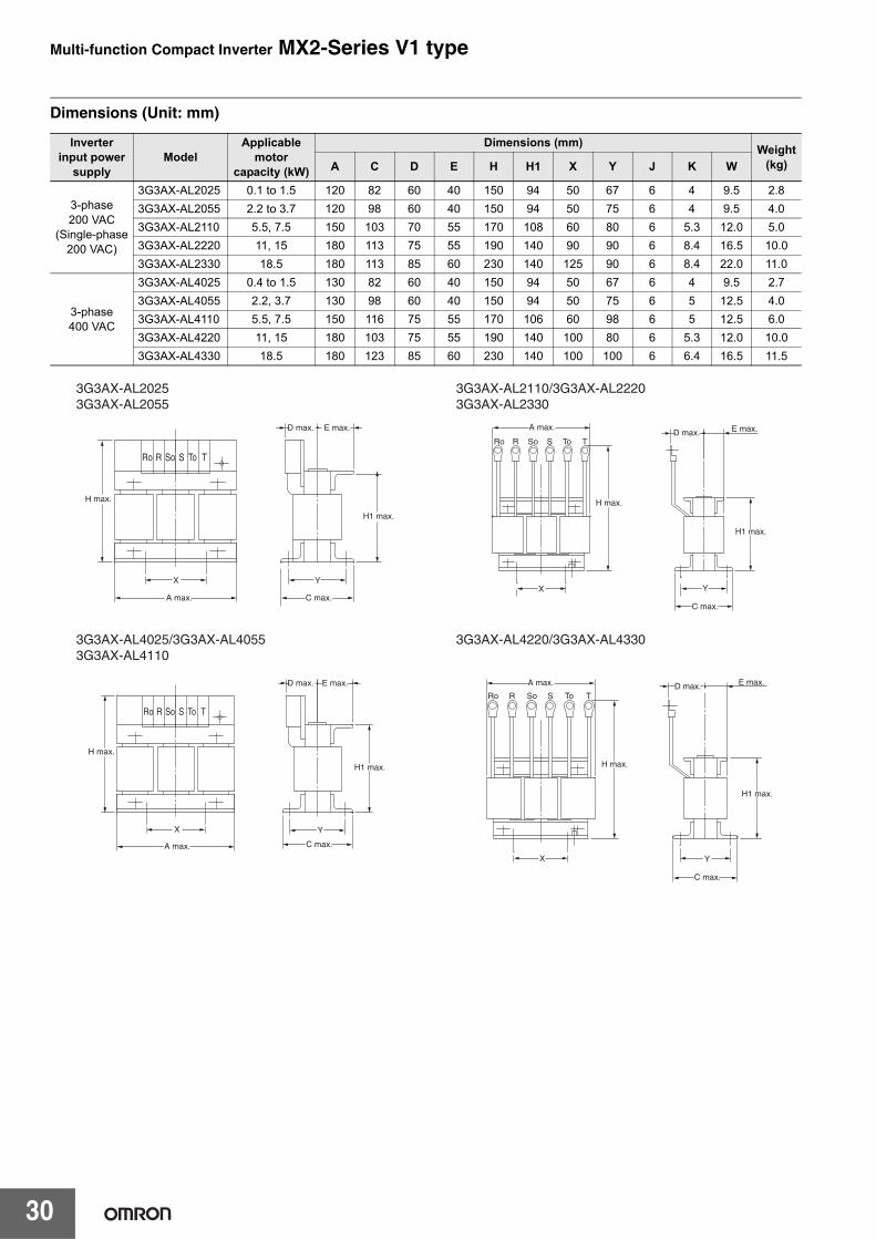
Dimensions (Unit: mm)
Inverter input power
supplyModel
Applicable motor
capacity (kW)
Dimensions (mm) Weight (kg)A C D E H H1 X Y J K W
3-phase 200 VAC
(Single-phase 200 VAC)
3G3AX-AL2025 0.1 to 1.5 120 82 60 40 150 94 50 67 6 4 9.5 2.83G3AX-AL2055 2.2 to 3.7 120 98 60 40 150 94 50 75 6 4 9.5 4.03G3AX-AL2110 5.5, 7.5 150 103 70 55 170 108 60 80 6 5.3 12.0 5.03G3AX-AL2220 11, 15 180 113 75 55 190 140 90 90 6 8.4 16.5 10.03G3AX-AL2330 18.5 180 113 85 60 230 140 125 90 6 8.4 22.0 11.0
3-phase 400 VAC
3G3AX-AL4025 0.4 to 1.5 130 82 60 40 150 94 50 67 6 4 9.5 2.73G3AX-AL4055 2.2, 3.7 130 98 60 40 150 94 50 75 6 5 12.5 4.03G3AX-AL4110 5.5, 7.5 150 116 75 55 170 106 60 98 6 5 12.5 6.03G3AX-AL4220 11, 15 180 103 75 55 190 140 100 80 6 5.3 12.0 10.03G3AX-AL4330 18.5 180 123 85 60 230 140 100 100 6 6.4 16.5 11.5
H max.
H1 max.
X Y
C max.
D max. E max.
A max.
R So S To TRo
A max.D max. E max.
X Y
C max.
H max.
H1 max.
R So S To TRo
A max.
X
H max.
H1 max.
D max. E max.
Y
C max.
Ro So ToR S T
Ro So ToR S T
H max.
H1 max.
X
A max.
D max. E max.
Y
C max.
3G3AX-AL20253G3AX-AL2055
3G3AX-AL4025/3G3AX-AL40553G3AX-AL4110
3G3AX-AL4220/3G3AX-AL4330
3G3AX-AL2110/3G3AX-AL22203G3AX-AL2330
Multi-function Compact Inverter MX2-Series V1 type
31
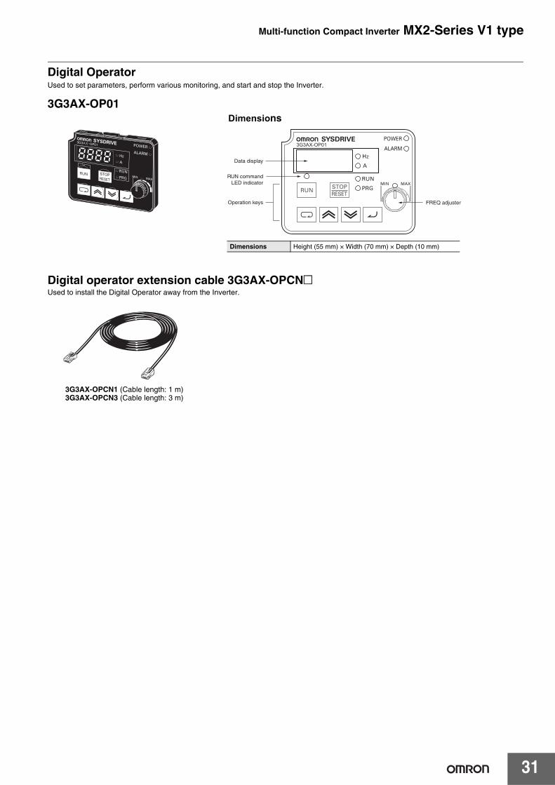
Digital OperatorUsed to set parameters, perform various monitoring, and start and stop the Inverter.
3G3AX-OP01
Digital operator extension cable 3G3AX-OPCN@Used to install the Digital Operator away from the Inverter.
Data display
Operation keys
RUN commandLED indicator
FREQ adjuster
Dimensions Height (55 mm) × Width (70 mm) × Depth (10 mm)
Dimensions
3G3AX-OPCN1 (Cable length: 1 m)3G3AX-OPCN3 (Cable length: 3 m)
Ordering Information
■ System Configuration.................................................................................33■ Interpreting Model Numbers ......................................................................34■ Ordering Information..................................................................................34
3G3MX2 Inverter Models .......................................................................................34
Communication Unit ..............................................................................................34
Related Options .....................................................................................................35
Recommended EtherCAT Communications Cables...........................................40
Software..................................................................................................................41■ Overview of Inverter Selection ..................................................................42■ Related Manuals..........................................................................................46
Sysmac is a trademark or registered trademark of OMRON Corporation in Japan and other countries for OMRON factory automation products.Windows is either registered trademarks or trademarks of Microsoft Corporation in the United States and/or other countries.EtherCAT® is registered trademark and patented technology, licensed by Beckhoff Automation GmbH, Germany.CompoNetTM and DeviceNetTM are the trademarks of ODVA.Other company names and product names in this document are the trademarks or registered trademarks of their respective companies.The product photographs and figures that are used in this catalog may vary somewhat from the actual products.Microsoft product screen shot(s) reprinted with permission from Microsoft Corporation.
Multi-function Compact Inverter MX2-Series V1 type
33
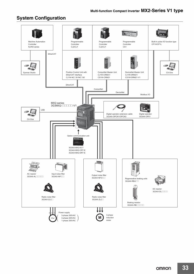
System Configuration
EtherCAT
EtherCAT
CompoNet
DeviceNet
Sysmac Studio CX-One
CX-One
USB
Machine Automation Controller NJ/NX-series
Programmable ControllerCJ2/CJ1
Programmable ControllerCJ2/CJ1
Programmable ControllerCS1
Built-in pulse I/O function typeCP1H/CP1L
Position Control Unit withEtherCAT interfaceCJ1W-NC@81/NC@82
CompoNet Master UnitCJ1W-CRM21/CS1W-CRM21
DeviceNet Master UnitCJ1W-DRM21/CS1W-DRM21-V1
Modbus I/O
Digital operator extension cable3G3AX-OPCN1/OPCN3
Digital operator3G3AX-OP01
MX2-series3G3MX2-@@@@@-V1
Option communication unit
Radio noise filter3G3AX-ZLC@
Input noise filter3G3AX-NFI@@
AC reactor3G3AX-AL@@@@@
Radio noise filter3G3AX-ZLC@
Output noise filter3G3AX-NFO@@ Regenerative braking units
3G3AX-RBU@@
Braking resistor3G3AX-RB@@@@@
DC reactor3G3AX-DL@@@@
3-phase 200VAC3-phase 400VAC1-phase 200VAC
Power supply
)(3-phaseinductionmotor
3G3AX-MX2-ECT3G3AX-MX2-CRT-E3G3AX-MX2-DRT-E
M S R T
Multi-function Compact Inverter MX2-Series V1 type
34
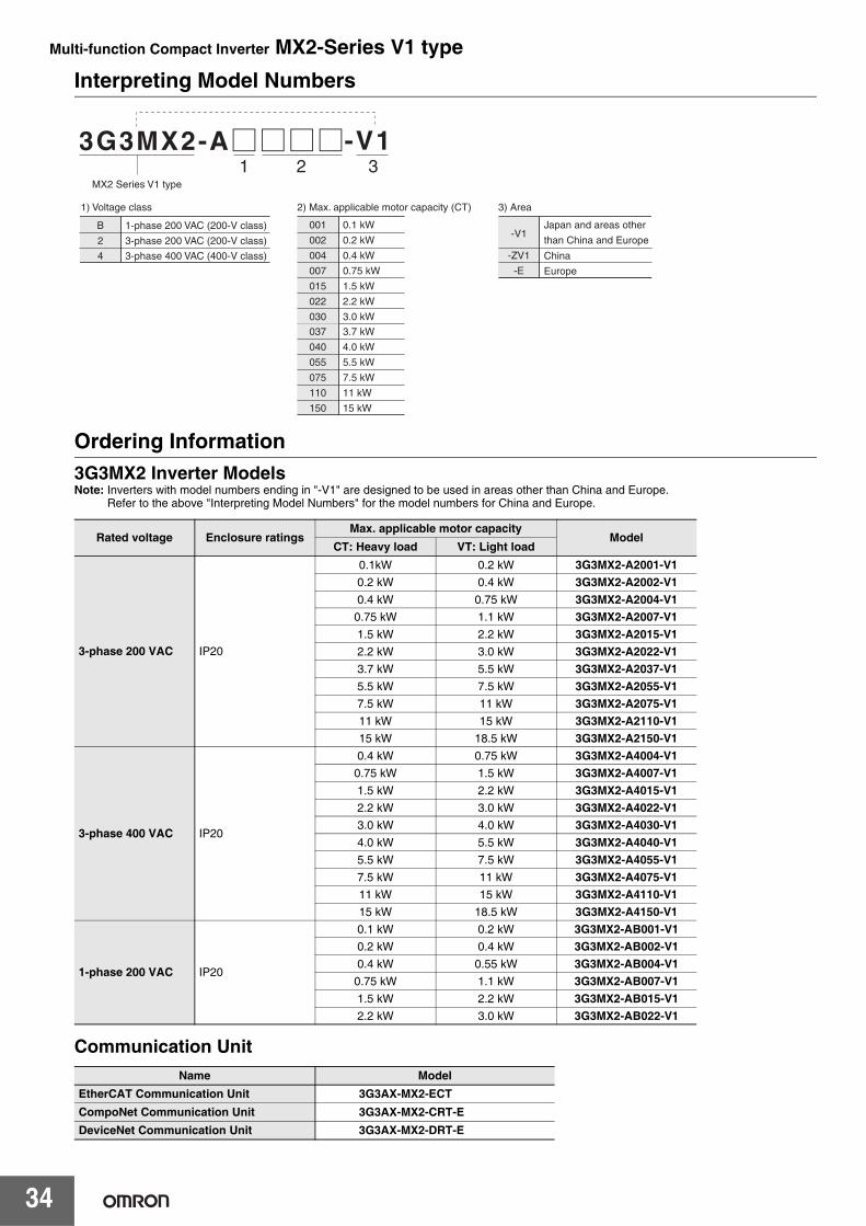
Interpreting Model Numbers
Ordering Information3G3MX2 Inverter ModelsNote: Inverters with model numbers ending in "-V1" are designed to be used in areas other than China and Europe.
Refer to the above "Interpreting Model Numbers" for the model numbers for China and Europe.
Communication Unit
Rated voltage Enclosure ratingsMax. applicable motor capacity
ModelCT: Heavy load VT: Light load
3-phase 200 VAC IP20
0.1kW 0.2 kW 3G3MX2-A2001-V10.2 kW 0.4 kW 3G3MX2-A2002-V10.4 kW 0.75 kW 3G3MX2-A2004-V10.75 kW 1.1 kW 3G3MX2-A2007-V11.5 kW 2.2 kW 3G3MX2-A2015-V12.2 kW 3.0 kW 3G3MX2-A2022-V13.7 kW 5.5 kW 3G3MX2-A2037-V15.5 kW 7.5 kW 3G3MX2-A2055-V17.5 kW 11 kW 3G3MX2-A2075-V111 kW 15 kW 3G3MX2-A2110-V115 kW 18.5 kW 3G3MX2-A2150-V1
3-phase 400 VAC IP20
0.4 kW 0.75 kW 3G3MX2-A4004-V10.75 kW 1.5 kW 3G3MX2-A4007-V11.5 kW 2.2 kW 3G3MX2-A4015-V12.2 kW 3.0 kW 3G3MX2-A4022-V13.0 kW 4.0 kW 3G3MX2-A4030-V14.0 kW 5.5 kW 3G3MX2-A4040-V15.5 kW 7.5 kW 3G3MX2-A4055-V17.5 kW 11 kW 3G3MX2-A4075-V111 kW 15 kW 3G3MX2-A4110-V115 kW 18.5 kW 3G3MX2-A4150-V1
1-phase 200 VAC IP20
0.1 kW 0.2 kW 3G3MX2-AB001-V10.2 kW 0.4 kW 3G3MX2-AB002-V10.4 kW 0.55 kW 3G3MX2-AB004-V10.75 kW 1.1 kW 3G3MX2-AB007-V11.5 kW 2.2 kW 3G3MX2-AB015-V12.2 kW 3.0 kW 3G3MX2-AB022-V1
Name ModelEtherCAT Communication Unit 3G3AX-MX2-ECTCompoNet Communication Unit 3G3AX-MX2-CRT-EDeviceNet Communication Unit 3G3AX-MX2-DRT-E
1) Voltage class
1 32-V1
001
002
004
007
015
022
030
0.1 kW
0.2 kW
0.4 kW
0.75 kW
1.5 kW
2.2 kW
3.0 kW
037
040
055
075
110
150
3.7 kW
4.0 kW
5.5 kW
7.5 kW
11 kW
15 kW
B
2
1-phase 200 VAC (200-V class)
3-phase 200 VAC (200-V class)
4 3-phase 400 VAC (400-V class)
MX2 Series V1 type
2) Max. applicable motor capacity (CT)
-V1
-ZV1
-E
Japan and areas other
than China and Europe
China
Europe
3) Area
Multi-function Compact Inverter MX2-Series V1 type
35
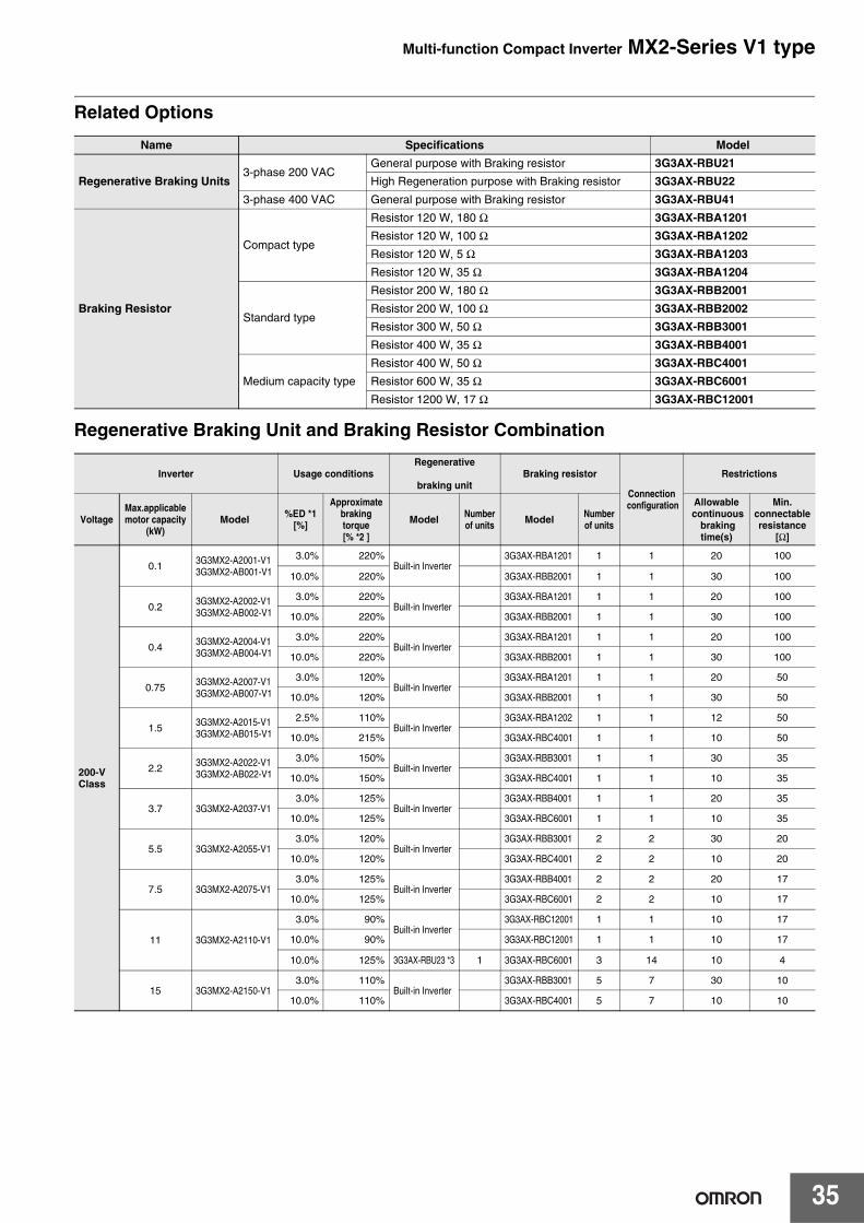
Related Options
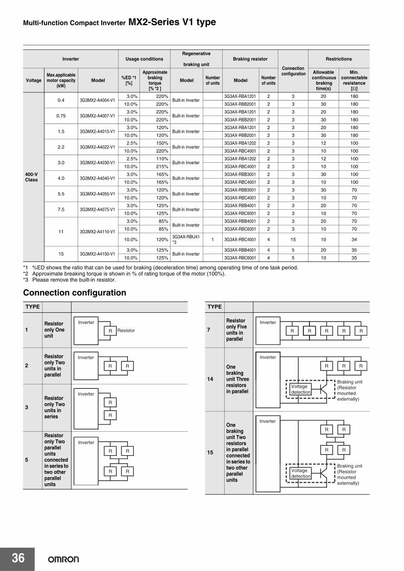
Regenerative Braking Unit and Braking Resistor Combination
Name Specifications Model
Regenerative Braking Units3-phase 200 VAC
General purpose with Braking resistor 3G3AX-RBU21
High Regeneration purpose with Braking resistor 3G3AX-RBU22
3-phase 400 VAC General purpose with Braking resistor 3G3AX-RBU41
Braking Resistor
Compact type
Resistor 120 W, 180 Ω 3G3AX-RBA1201
Resistor 120 W, 100 Ω 3G3AX-RBA1202
Resistor 120 W, 5 Ω 3G3AX-RBA1203
Resistor 120 W, 35 Ω 3G3AX-RBA1204
Standard type
Resistor 200 W, 180 Ω 3G3AX-RBB2001
Resistor 200 W, 100 Ω 3G3AX-RBB2002
Resistor 300 W, 50 Ω 3G3AX-RBB3001
Resistor 400 W, 35 Ω 3G3AX-RBB4001
Medium capacity type
Resistor 400 W, 50 Ω 3G3AX-RBC4001
Resistor 600 W, 35 Ω 3G3AX-RBC6001
Resistor 1200 W, 17 Ω 3G3AX-RBC12001
Inverter Usage conditionsRegenerative
braking unit
Braking resistor
Connection configuration
Restrictions
VoltageMax.applicable motor capacity
(kW)Model %ED *1
[%]
Approximate braking torque[% *2 ]
Model Number of units Model Number
of units
Allowable continuous
braking time(s)
Min.connectableresistance
[Ω]
200-V Class
0.1 3G3MX2-A2001-V13G3MX2-AB001-V1
3.0% 220%Built-in Inverter
3G3AX-RBA1201 1 1 20 100
10.0% 220% 3G3AX-RBB2001 1 1 30 100
0.2 3G3MX2-A2002-V13G3MX2-AB002-V1
3.0% 220%Built-in Inverter
3G3AX-RBA1201 1 1 20 100
10.0% 220% 3G3AX-RBB2001 1 1 30 100
0.4 3G3MX2-A2004-V13G3MX2-AB004-V1
3.0% 220%Built-in Inverter
3G3AX-RBA1201 1 1 20 100
10.0% 220% 3G3AX-RBB2001 1 1 30 100
0.75 3G3MX2-A2007-V13G3MX2-AB007-V1
3.0% 120%Built-in Inverter
3G3AX-RBA1201 1 1 20 50
10.0% 120% 3G3AX-RBB2001 1 1 30 50
1.5 3G3MX2-A2015-V13G3MX2-AB015-V1
2.5% 110%Built-in Inverter
3G3AX-RBA1202 1 1 12 50
10.0% 215% 3G3AX-RBC4001 1 1 10 50
2.2 3G3MX2-A2022-V13G3MX2-AB022-V1
3.0% 150%Built-in Inverter
3G3AX-RBB3001 1 1 30 35
10.0% 150% 3G3AX-RBC4001 1 1 10 35
3.7 3G3MX2-A2037-V13.0% 125%
Built-in Inverter3G3AX-RBB4001 1 1 20 35
10.0% 125% 3G3AX-RBC6001 1 1 10 35
5.5 3G3MX2-A2055-V13.0% 120%
Built-in Inverter3G3AX-RBB3001 2 2 30 20
10.0% 120% 3G3AX-RBC4001 2 2 10 20
7.5 3G3MX2-A2075-V13.0% 125%
Built-in Inverter3G3AX-RBB4001 2 2 20 17
10.0% 125% 3G3AX-RBC6001 2 2 10 17
11 3G3MX2-A2110-V1
3.0% 90%Built-in Inverter
3G3AX-RBC12001 1 1 10 17
10.0% 90% 3G3AX-RBC12001 1 1 10 17
10.0% 125% 3G3AX-RBU23 *3 1 3G3AX-RBC6001 3 14 10 4
15 3G3MX2-A2150-V13.0% 110%
Built-in Inverter3G3AX-RBB3001 5 7 30 10
10.0% 110% 3G3AX-RBC4001 5 7 10 10
Multi-function Compact Inverter MX2-Series V1 type
36
*1 %ED shows the ratio that can be used for braking (deceleration time) among operating time of one task period. *2 Approximate breaking torque is shown in % of rating torque of the motor (100%). *3 Please remove the built-in resistor.
Connection configuration
400-V Class
0.4 3G3MX2-A4004-V13.0% 220%
Built-in Inverter3G3AX-RBA1201 2 3 20 180
10.0% 220% 3G3AX-RBB2001 2 3 30 180
0.75 3G3MX2-A4007-V13.0% 220%
Built-in Inverter3G3AX-RBA1201 2 3 20 180
10.0% 220% 3G3AX-RBB2001 2 3 30 180
1.5 3G3MX2-A4015-V13.0% 120%
Built-in Inverter3G3AX-RBA1201 2 3 20 180
10.0% 120% 3G3AX-RBB2001 2 3 30 180
2.2 3G3MX2-A4022-V12.5% 150%
Built-in Inverter3G3AX-RBA1202 2 3 12 100
10.0% 220% 3G3AX-RBC4001 2 3 10 100
3.0 3G3MX2-A4030-V12.5% 110%
Built-in Inverter3G3AX-RBA1202 2 3 12 100
10.0% 215% 3G3AX-RBC4001 2 3 10 100
4.0 3G3MX2-A4040-V13.0% 165%
Built-in Inverter3G3AX-RBB3001 2 3 30 100
10.0% 165% 3G3AX-RBC4001 2 3 10 100
5.5 3G3MX2-A4055-V13.0% 120%
Built-in Inverter3G3AX-RBB3001 2 3 30 70
10.0% 120% 3G3AX-RBC4001 2 3 10 70
7.5 3G3MX2-A4075-V13.0% 125%
Built-in Inverter3G3AX-RBB4001 2 3 20 70
10.0% 125% 3G3AX-RBC6001 2 3 10 70
11 3G3MX2-A4110-V1
3.0% 85%Built-in Inverter
3G3AX-RBB4001 2 3 20 70
10.0% 85% 3G3AX-RBC6001 2 3 10 70
10.0% 120% 3G3AX-RBU41 *3 1 3G3AX-RBC4001 4 15 10 34
15 3G3MX2-A4150-V13.0% 125%
Built-in Inverter3G3AX-RBB4001 4 5 20 35
10.0% 125% 3G3AX-RBC6001 4 5 10 35
Inverter Usage conditionsRegenerative
braking unit
Braking resistor
Connection configuration
Restrictions
VoltageMax.applicable motor capacity
(kW)Model %ED *1
[%]
Approximate braking torque[% *2 ]
Model Number of units Model Number
of units
Allowable continuous
braking time(s)
Min.connectableresistance
[Ω]
TYPE
1Resistor only One unit
2
Resistor only Two units in parallel
3
Resistor only Two units in series
5
Resistor only Two parallel units connected in series to two other parallel units
Inverter
ResistorR
Inverter
R R
Inverter
R
R
Inverter
R
R
R
R
TYPE
7
Resistor only Five units in parallel
14
One braking unit Three resistors in parallel
15
One braking unit Two resistors in parallel connected in series to two other parallel units
Inverter
R R R R R
Inverter
Braking unit(Resistor mounted externally)
Voltage detection
R RR
Inverter
Braking unit(Resistor mounted externally)
Voltage detection
R
R
R
R
Multi-function Compact Inverter MX2-Series V1 type
37
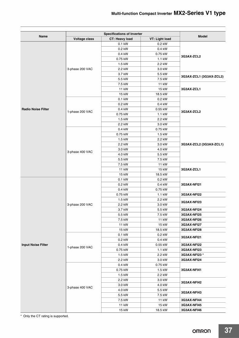
* Only the CT rating is supported.
NameSpecifications of Inverter
ModelVoltage class CT: Heavy load VT: Light load
Radio Noise Filter
3-phase 200 VAC
0.1 kW 0.2 kW
3G3AX-ZCL2
0.2 kW 0.4 kW
0.4 kW 0.75 kW
0.75 kW 1.1 kW
1.5 kW 2.2 kW
2.2 kW 3.0 kW
3.7 kW 5.5 kW3G3AX-ZCL1 (3G3AX-ZCL2)
5.5 kW 7.5 kW
7.5 kW 11 kW
3G3AX-ZCL111 kW 15 kW
15 kW 18.5 kW
1-phase 200 VAC
0.1 kW 0.2 kW
3G3AX-ZCL2
0.2 kW 0.4 kW
0.4 kW 0.55 kW
0.75 kW 1.1 kW
1.5 kW 2.2 kW
2.2 kW 3.0 kW
3-phase 400 VAC
0.4 kW 0.75 kW
3G3AX-ZCL2 (3G3AX-ZCL1)
0.75 kW 1.5 kW
1.5 kW 2.2 kW
2.2 kW 3.0 kW
3.0 kW 4.0 kW
4.0 kW 5.5 kW
5.5 kW 7.5 kW
7.5 kW 11 kW
3G3AX-ZCL111 kW 15 kW
15 kW 18.5 kW
Input Noise Filter
3-phase 200 VAC
0.1 kW 0.2 kW
3G3AX-NFI210.2 kW 0.4 kW
0.4 kW 0.75 kW
0.75 kW 1.1 kW 3G3AX-NFI22
1.5 kW 2.2 kW3G3AX-NFI23
2.2 kW 3.0 kW
3.7 kW 5.5 kW 3G3AX-NFI24
5.5 kW 7.5 kW 3G3AX-NFI25
7.5 kW 11 kW 3G3AX-NFI26
11 kW 15 kW 3G3AX-NFI27
15 kW 18.5 kW 3G3AX-NFI28
1-phase 200 VAC
0.1 kW 0.2 kW3G3AX-NFI21
0.2 kW 0.4 kW
0.4 kW 0.55 kW 3G3AX-NFI22
0.75 kW 1.1 kW 3G3AX-NFI23
1.5 kW 2.2 kW 3G3AX-NFI23 *
2.2 kW 3.0 kW 3G3AX-NFI24
3-phase 400 VAC
0.4 kW 0.75 kW
3G3AX-NFI410.75 kW 1.5 kW
1.5 kW 2.2 kW
2.2 kW 3.0 kW3G3AX-NFI42
3.0 kW 4.0 kW
4.0 kW 5.5 kW3G3AX-NFI43
5.5 kW 7.5 kW
7.5 kW 11 kW 3G3AX-NFI44
11 kW 15 kW 3G3AX-NFI45
15 kW 18.5 kW 3G3AX-NFI46

Multi-function Compact Inverter MX2-Series V1 type
38
NameSpecifications of Inverter
ModelVoltage class CT: Heavy load VT: Light load
Output Noise Filter
3-phase 200 VAC
0.1 kW 0.2 kW
3G3AX-NFO010.2 kW 0.4 kW
0.4 kW 0.75 kW
0.75 kW 1.1 kW3G3AX-NFO02
1.5 kW 2.2 kW
2.2 kW 3.0 kW3G3AX-NFO03
3.7 kW 5.5 kW
5.5 kW 7.5 kW3G3AX-NFO04
7.5 kW 11 kW
11 kW 15 kW 3G3AX-NFO05
1-phase 200 VAC
0.1 kW 0.2 kW3G3AX-NFO01
0.2 kW 0.4 kW
0.4 kW 0.55 kW3G3AX-NFO02
0.75 kW 1.1 kW
1.5 kW 2.2 kW3G3AX-NFO03
2.2 kW 3.0 kW
3-phase 400 VAC
0.4 kW 0.75 kW3G3AX-NFO01
0.75 kW 1.5 kW
1.5 kW 2.2 kW
3G3AX-NFO022.2 kW 3.0 kW
3.0 kW 4.0 kW
4.0 kW 5.5 kW
3G3AX-NFO035.5 kW 7.5 kW
7.5 kW 11 kW
11 kW 15 kW3G3AX-NFO04
15 kW 18.5 kW
DC Reactor
3-phase 200 VAC
0.1 kW 0.2 kW 3G3AX-DL20020.2 kW 0.4 kW 3G3AX-DL20040.4 kW 0.75 kW 3G3AX-DL2007
0.75 kW 1.1 kW 3G3AX-DL20151.5 kW 2.2 kW 3G3AX-DL20222.2 kW 3.0 kW 3G3AX-DL20373.7 kW 5.5 kW 3G3AX-DL20555.5 kW 7.5 kW 3G3AX-DL20757.5 kW 11 kW 3G3AX-DL211011 kW 15 kW 3G3AX-DL215015 kW 18.5 kW 3G3AX-DL2220
1-phase 200 VAC
0.1 kW 0.2 kW 3G3AX-DL20020.2 kW 0.4 kW 3G3AX-DL20040.4 kW 0.55 kW 3G3AX-DL2007
0.75 kW 1.1 kW 3G3AX-DL20151.5 kW 2.2 kW 3G3AX-DL20222.2 kW 3.0 kW 3G3AX-DL2037
3-phase 400 VAC
0.4 kW 0.75 kW 3G3AX-DL40070.75 kW 1.5 kW 3G3AX-DL4015 *
1.5 kW 2.2 kW 3G3AX-DL40222.2 kW 3.0 kW
3G3AX-DL40373.0 kW 4.0 kW
4.0 kW 5.5 kW 3G3AX-DL40555.5 kW 7.5 kW 3G3AX-DL4075 *7.5 kW 11 kW 3G3AX-DL4110 *11 kW 15 kW 3G3AX-DL415015 kW 18.5 kW 3G3AX-DL4220
Multi-function Compact Inverter MX2-Series V1 type
39
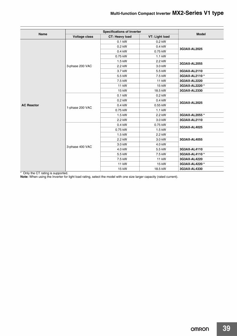
* Only the CT rating is supported.Note: When using the Inverter for light load rating, select the model with one size larger capacity (rated current).
AC Reactor
3-phase 200 VAC
0.1 kW 0.2 kW
3G3AX-AL20250.2 kW 0.4 kW0.4 kW 0.75 kW
0.75 kW 1.1 kW1.5 kW 2.2 kW
3G3AX-AL20552.2 kW 3.0 kW3.7 kW 5.5 kW 3G3AX-AL21105.5 kW 7.5 kW 3G3AX-AL2110 *7.5 kW 11 kW 3G3AX-AL222011 kW 15 kW 3G3AX-AL2220 *15 kW 18.5 kW 3G3AX-AL2330
1-phase 200 VAC
0.1 kW 0.2 kW
3G3AX-AL20250.2 kW 0.4 kW0.4 kW 0.55 kW
0.75 kW 1.1 kW1.5 kW 2.2 kW 3G3AX-AL2055 *2.2 kW 3.0 kW 3G3AX-AL2110
3-phase 400 VAC
0.4 kW 0.75 kW3G3AX-AL4025
0.75 kW 1.5 kW1.5 kW 2.2 kW
3G3AX-AL40552.2 kW 3.0 kW3.0 kW 4.0 kW
4.0 kW 5.5 kW 3G3AX-AL41105.5 kW 7.5 kW 3G3AX-AL4110 *7.5 kW 11 kW 3G3AX-AL422011 kW 15 kW 3G3AX-AL4220 *15 kW 18.5 kW 3G3AX-AL4330
NameSpecifications of Inverter
ModelVoltage class CT: Heavy load VT: Light load
Multi-function Compact Inverter MX2-Series V1 type
40
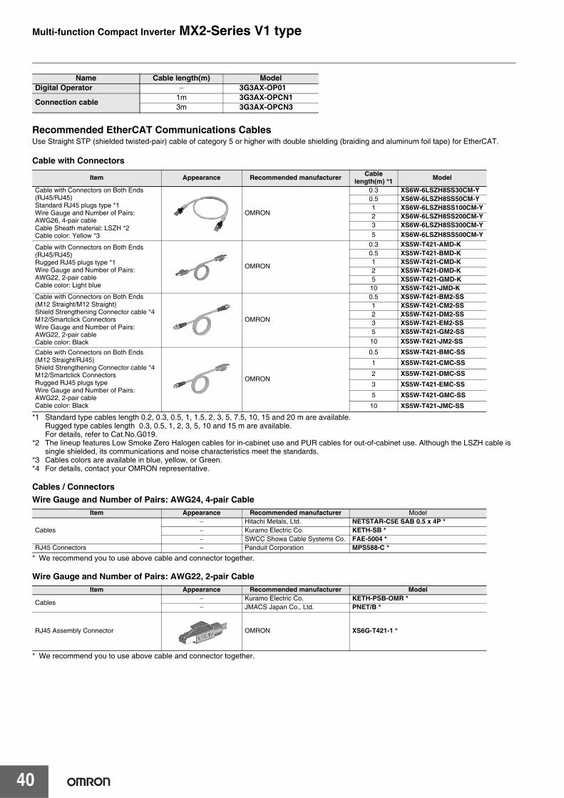
Recommended EtherCAT Communications CablesUse Straight STP (shielded twisted-pair) cable of category 5 or higher with double shielding (braiding and aluminum foil tape) for EtherCAT.
Cable with Connectors
*1 Standard type cables length 0.2, 0.3, 0.5, 1, 1.5, 2, 3, 5, 7.5, 10, 15 and 20 m are available. Rugged type cables length 0.3, 0.5, 1, 2, 3, 5, 10 and 15 m are available.For details, refer to Cat.No.G019.
*2 The lineup features Low Smoke Zero Halogen cables for in-cabinet use and PUR cables for out-of-cabinet use. Although the LSZH cable is single shielded, its communications and noise characteristics meet the standards.
*3 Cables colors are available in blue, yellow, or Green.*4 For details, contact your OMRON representative.
Cables / ConnectorsWire Gauge and Number of Pairs: AWG24, 4-pair Cable
* We recommend you to use above cable and connector together.
Wire Gauge and Number of Pairs: AWG22, 2-pair Cable
* We recommend you to use above cable and connector together.
Name Cable length(m) ModelDigital Operator − 3G3AX-OP01
Connection cable 1m 3G3AX-OPCN13m 3G3AX-OPCN3
Item Appearance Recommended manufacturer Cable length(m) *1 Model
Cable with Connectors on Both Ends (RJ45/RJ45)Standard RJ45 plugs type *1Wire Gauge and Number of Pairs: AWG26, 4-pair cableCable Sheath material: LSZH *2Cable color: Yellow *3
OMRON
0.3 XS6W-6LSZH8SS30CM-Y0.5 XS6W-6LSZH8SS50CM-Y1 XS6W-6LSZH8SS100CM-Y2 XS6W-6LSZH8SS200CM-Y3 XS6W-6LSZH8SS300CM-Y5 XS6W-6LSZH8SS500CM-Y
Cable with Connectors on Both Ends (RJ45/RJ45)Rugged RJ45 plugs type *1Wire Gauge and Number of Pairs: AWG22, 2-pair cableCable color: Light blue
OMRON
0.3 XS5W-T421-AMD-K0.5 XS5W-T421-BMD-K1 XS5W-T421-CMD-K2 XS5W-T421-DMD-K 5 XS5W-T421-GMD-K 10 XS5W-T421-JMD-K
Cable with Connectors on Both Ends (M12 Straight/M12 Straight)Shield Strengthening Connector cable *4M12/Smartclick ConnectorsWire Gauge and Number of Pairs: AWG22, 2-pair cableCable color: Black
OMRON
0.5 XS5W-T421-BM2-SS1 XS5W-T421-CM2-SS2 XS5W-T421-DM2-SS3 XS5W-T421-EM2-SS5 XS5W-T421-GM2-SS10 XS5W-T421-JM2-SS
Cable with Connectors on Both Ends (M12 Straight/RJ45)Shield Strengthening Connector cable *4M12/Smartclick ConnectorsRugged RJ45 plugs type Wire Gauge and Number of Pairs: AWG22, 2-pair cableCable color: Black
OMRON
0.5 XS5W-T421-BMC-SS1 XS5W-T421-CMC-SS2 XS5W-T421-DMC-SS3 XS5W-T421-EMC-SS5 XS5W-T421-GMC-SS10 XS5W-T421-JMC-SS
Item Appearance Recommended manufacturer Model
Cables− Hitachi Metals, Ltd. NETSTAR-C5E SAB 0.5 x 4P *− Kuramo Electric Co. KETH-SB *− SWCC Showa Cable Systems Co. FAE-5004 *
RJ45 Connectors − Panduit Corporation MPS588-C *
Item Appearance Recommended manufacturer Model
Cables− Kuramo Electric Co. KETH-PSB-OMR *− JMACS Japan Co., Ltd. PNET/B *
RJ45 Assembly Connector OMRON XS6G-T421-1 *
Multi-function Compact Inverter MX2-Series V1 type
41
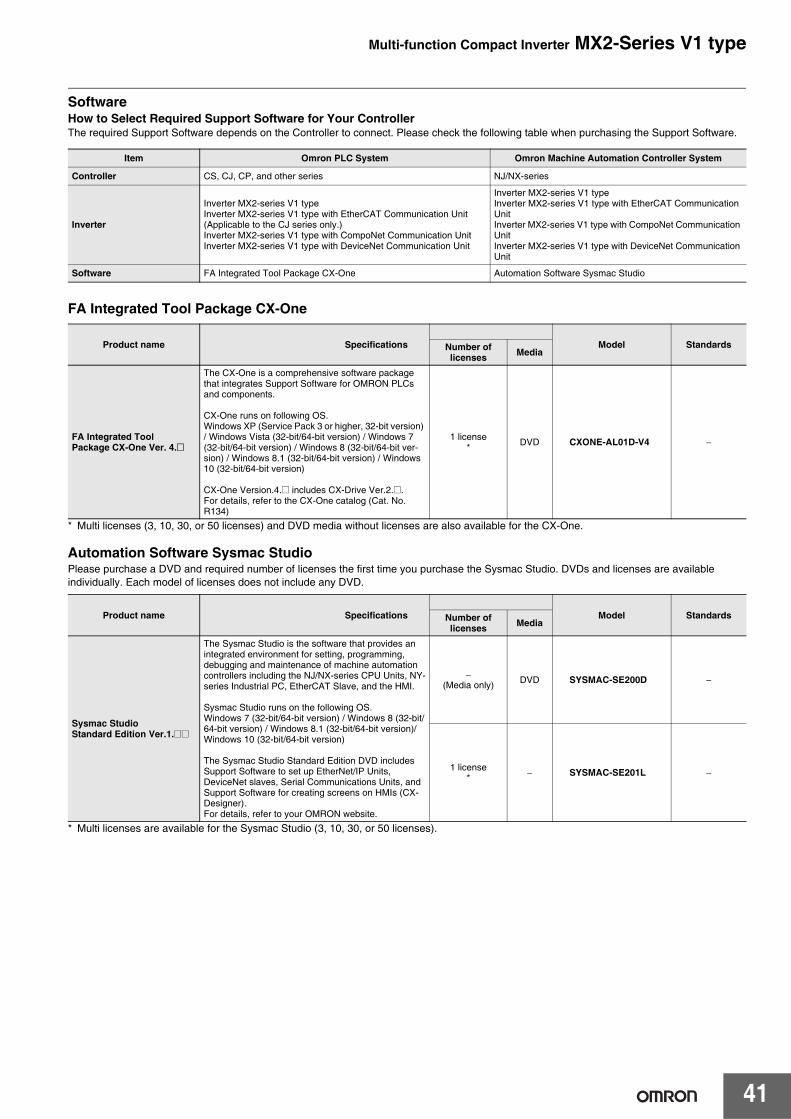
SoftwareHow to Select Required Support Software for Your ControllerThe required Support Software depends on the Controller to connect. Please check the following table when purchasing the Support Software.
FA Integrated Tool Package CX-One
* Multi licenses (3, 10, 30, or 50 licenses) and DVD media without licenses are also available for the CX-One.
Automation Software Sysmac StudioPlease purchase a DVD and required number of licenses the first time you purchase the Sysmac Studio. DVDs and licenses are available individually. Each model of licenses does not include any DVD.
* Multi licenses are available for the Sysmac Studio (3, 10, 30, or 50 licenses).
Item Omron PLC System Omron Machine Automation Controller System
Controller CS, CJ, CP, and other series NJ/NX-series
Inverter
Inverter MX2-series V1 typeInverter MX2-series V1 type with EtherCAT Communication Unit (Applicable to the CJ series only.)Inverter MX2-series V1 type with CompoNet Communication UnitInverter MX2-series V1 type with DeviceNet Communication Unit
Inverter MX2-series V1 typeInverter MX2-series V1 type with EtherCAT Communication UnitInverter MX2-series V1 type with CompoNet Communication UnitInverter MX2-series V1 type with DeviceNet Communication Unit
Software FA Integrated Tool Package CX-One Automation Software Sysmac Studio
Product name Specifications Model StandardsNumber of licenses Media
FA Integrated ToolPackage CX-One Ver. 4.@
The CX-One is a comprehensive software package that integrates Support Software for OMRON PLCs and components.
CX-One runs on following OS.Windows XP (Service Pack 3 or higher, 32-bit version) / Windows Vista (32-bit/64-bit version) / Windows 7 (32-bit/64-bit version) / Windows 8 (32-bit/64-bit ver-sion) / Windows 8.1 (32-bit/64-bit version) / Windows 10 (32-bit/64-bit version)
CX-One Version.4.@ includes CX-Drive [email protected] details, refer to the CX-One catalog (Cat. No. R134)
1 license* DVD CXONE-AL01D-V4 −
Product name Specifications Model StandardsNumber of licenses Media
Sysmac Studio Standard Edition Ver.1.@@
The Sysmac Studio is the software that provides an integrated environment for setting, programming, debugging and maintenance of machine automation controllers including the NJ/NX-series CPU Units, NY-series Industrial PC, EtherCAT Slave, and the HMI.
Sysmac Studio runs on the following OS.Windows 7 (32-bit/64-bit version) / Windows 8 (32-bit/64-bit version) / Windows 8.1 (32-bit/64-bit version)/ Windows 10 (32-bit/64-bit version)
The Sysmac Studio Standard Edition DVD includes Support Software to set up EtherNet/IP Units, DeviceNet slaves, Serial Communications Units, and Support Software for creating screens on HMIs (CX-Designer).For details, refer to your OMRON website.
−(Media only) DVD SYSMAC-SE200D −
1 license* − SYSMAC-SE201L −
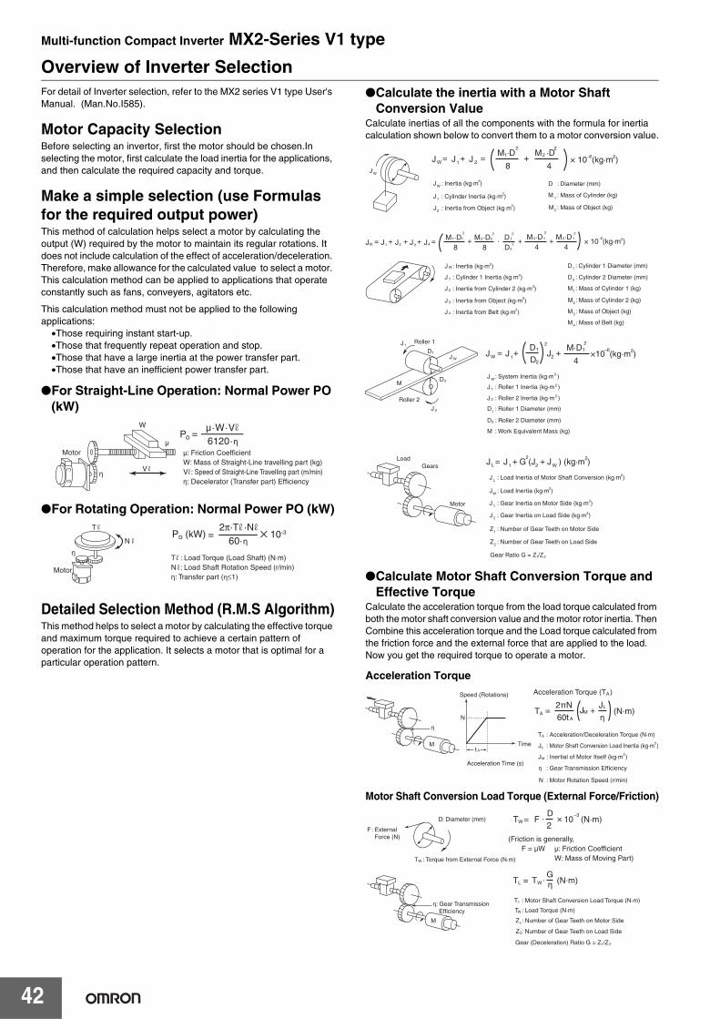
Multi-function Compact Inverter MX2-Series V1 type
42
Overview of Inverter SelectionFor detail of Inverter selection, refer to the MX2 series V1 type User's Manual. (Man.No.I585).
Motor Capacity SelectionBefore selecting an invertor, first the motor should be chosen.In selecting the motor, first calculate the load inertia for the applications, and then calculate the required capacity and torque.
Make a simple selection (use Formulas for the required output power) This method of calculation helps select a motor by calculating the output (W) required by the motor to maintain its regular rotations. It does not include calculation of the effect of acceleration/deceleration. Therefore, make allowance for the calculated value to select a motor. This calculation method can be applied to applications that operate constantly such as fans, conveyers, agitators etc.
This calculation method must not be applied to the following applications:
•Those requiring instant start-up.•Those that frequently repeat operation and stop.•Those that have a large inertia at the power transfer part.•Those that have an inefficient power transfer part.
●For Straight-Line Operation: Normal Power PO (kW)
●For Rotating Operation: Normal Power PO (kW)
Detailed Selection Method (R.M.S Algorithm)This method helps to select a motor by calculating the effective torque and maximum torque required to achieve a certain pattern of operation for the application. It selects a motor that is optimal for a particular operation pattern.
●Calculate the inertia with a Motor Shaft Conversion Value
Calculate inertias of all the components with the formula for inertia calculation shown below to convert them to a motor conversion value.
●Calculate Motor Shaft Conversion Torque and Effective Torque
Calculate the acceleration torque from the load torque calculated from both the motor shaft conversion value and the motor rotor inertia. Then Combine this acceleration torque and the Load torque calculated from the friction force and the external force that are applied to the load. Now you get the required torque to operate a motor.
Acceleration Torque
Motor Shaft Conversion Load Torque (External Force/Friction)
: Speed of Straight-Line Travelling part (m/min)
µ·W·V6120·η
Po =
Motor
η
W
V
µ
W: Mass of Straight-Line travelling part (kg)Vη: Decelerator (Transfer part) Efficiency
µ: Friction Coefficient
Motor
T
N
T : Load Torque (Load Shaft) (N·m)N : Load Shaft Rotation Speed (r/min)η: Transfer part (η≤1)
η60·η
=2π·T ·N
Po (kW) ✕ 10-3
JW
J JW 1 J 2= =
8 4+ × 10 (kg·m )
M ·D M ·D+ 1
2 2
–6 22
: Diameter (mm)D
: Mass of Cylinder (kg)M 1
: Inertia from Object (kg·m )J22
: Cylinder Inertia (kg·m )J12
: Mass of Object (kg)M2
: Inertia (kg·m )JW2
J JW 1 J2= + J3 J4++8 8 D
+ += ·M ·D M ·D D1 1
2
1
22
2 2
× 10 (kg·m )–6 22 2
4 4+M ·D M ·D3 1
2 24 1
: Inertia (kg·m )
: Cylinder 1 Inertia (kg·m )
: Inertia from Cylinder 2 (kg·m )
: Inertia from Object (kg·m )
: Inertia from Belt (kg·m )
J
J
J
J
J
2
2
2
2
2
2
1
W
3
4
: Cylinder 1 Diameter (mm)D1
: Cylinder 2 Diameter (mm)D2
: Mass of Cylinder 1 (kg)M1
: Mass of Cylinder 2 (kg)M2
: Mass of Object (kg)M3
: Mass of Belt (kg)M4
Roller 1
Roller 2
J
M
1
J W
J 2
D2
D1 J JW 1
1
2
J2=4
×10 (kg·m )M·D
+ +D
D 2 2–6 21
: System Inertia (kg·m )
: Roller 1 Inertia (kg·m )
: Work Equivalent Mass (kg)
: Roller 2 Inertia (kg·m )
: Roller 1 Diameter (mm)
: Roller 2 Diameter (mm)
J
J
M
J
D
D
2
2
W
2
1
2
1
2
LoadGears
Motor
J J G (J J ) (kg·m )L 1
2= +
2 W+ 2
1 2
: Gear Inertia on Motor Side (kg·m )J 1
: Number of Gear Teeth on Motor Side
Gear Ratio G = Z /Z
Z1
: Load Inertia of Motor Shaft Conversion (kg·m )J L2
: Gear Inertia on Load Side (kg·m )J 22
: Number of Gear Teeth on Load SideZ2
: Load Inertia (kg·m )J 2
2
W
: Motor Rotation Speed (r/min)N
: Acceleration/Deceleration Torque (N·m)T
: Inertial of Motor Itself (kg·m )JM2
A
: Motor Shaft Conversion Load Inertia (kg·m )JLA
A
2
T JAA
ML= + (N·m)
60t η2πN J
Acceleration Torque (T )
N
Acceleration Time (s)
Speed (Rotations)
Timet
η
η : Gear Transmission Efficiency
M
: Torque from External Force (N·m)TW
: Diameter (mm)D
: External Force (N)
F
(Friction is generally,F = µW µ: Friction Coefficient W: Mass of Moving Part)
T 10W–3
= F · × (N·m)2
D
T1
Z1
TW
2
η: Gear Transmission Efficiency
η
Z : Number of Gear Teeth on Load Side
M
TL W= T · (N·m)G
1 2Gear (Deceleration) Ratio G = Z /Z
: Motor Shaft Conversion Load Torque (N·m)
: Number of Gear Teeth on Motor Side
: Load Torque (N·m)
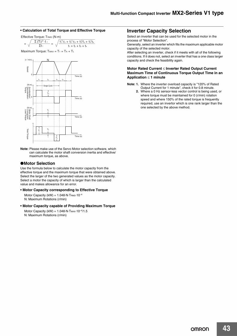
Multi-function Compact Inverter MX2-Series V1 type
43
• Calculation of Total Torque and Effective Torque
Note: Please make use of the Servo Motor selection software, which can calculate the motor shaft conversion inertia and effective/maximum torque, as above.
●Motor SelectionUse the formula below to calculate the motor capacity from the effective torque and the maximum torque that were obtained above.Select the larger of the two generated values as the motor capacity.Select a motor the capacity of which is larger than the calculated value and makes allowance for an error.
• Motor Capacity corresponding to Effective TorqueMotor Capacity (kW) = 1.048·N·TRMS·10–4
N: Maximum Rotations (r/min)
• Motor Capacity capable of Providing Maximum TorqueMotor Capacity (kW) = 1.048·N·TMAX·10–4/1.5N: Maximum Rotations (r/min)
Inverter Capacity SelectionSelect an inverter that can be used for the selected motor in the process of "Motor Selection". Generally, select an inverter which fits the maximum applicable motor capacity of the selected motor. After selecting an inverter, check if it meets with all of the following conditions. If it does not, select an inverter that has a one class larger capacity and check the feasibility again.
Motor Rated Current ≤ Inverter Rated Output CurrentMaximum Time of Continuous Torque Output Time in an Application ≤ 1 minute
Note: 1. Where the inverter overload capacity is "120% of Rated Output Current for 1 minute", check it for 0.8 minute.
2. Where a 0 Hz sensor-less vector control is being used, or where torque must be maintained for 0 (r/min) rotation speed and where 150% of the rated torque is frequently required, use an invertor which is one rank larger than the one selected by the above method.
(N·m)
(N·m)
Time (s)0
Single Cycle
0
T
Time (s)
Time (s)
Time (s)
A
t 1 t 2 t 3 t 4
TL
T2T1
T3
(r / min) N
Effective Torque: TRMS (N·m)
Σ (Ti) 2 ·t i
Σt i
Maximum Torque: TMAX = T1 = TA + TL
==t1 + t2 + t3 + t4
21 1T 2
2T·t 2·t 3·t+ 23T+ 4·t2
4T+
Speed
Acceleration/
Decceleration
Torque
Motor S
haft C
onversion Load Torque
Total Torque

Multi-function Compact Inverter MX2-Series V1 type
44
Outline of Braking Resistor SelectionImportance of Braking ResistorIf the regenerative energy generated in deceleration or descent in an application is too great, the main circuit of an inverter may have an increased voltage and it may be damaged. Because the inverter usually contains the overvoltage LAD stop function, it is not actually damaged. However, the motor stops detecting an error, making a stable and continuous operation disabled. Therefore, you must discharge the regenerative energy outside of the inverter.
● What is Regenerative Energy?A load connected to a motor has kinetic energy when rotating, and potential energy when it is located in a high position. When the motor decelerates, or when the load descends, the energy is returned to an inverter. It is known as regeneration, and the energy generated by the phenomenon is known as regenerative energy.
● Preventing Breaking ResistenceThe following are methods to prevent the connection of braking resistance.These methods will make the deceleration time increase, so check if it will not cause problems.• Enable the deceleration stall prevention (enabled in factory
settings) (It will automatically increase deceleration time not to cause an overvoltage to stop the motor).
• Set a longer deceleration time. (Cause the regenerative energy to decrease per unit of time.)
• Disable Free-Run. (Prevent the regenerative energy from returning to an inverter.)
Make a Simple Selection for Braking ResistorsIt can be a simple selecting method by using the ratio of time in whichregenerative energy is produced in a normal operating pattern.Calculate the usage ratio from the following operating pattern.
● For Models with a Built-in Braking Circuit
(3G3MX2 Max. 22 kW)Select the braking resistor based on the usage rate calculatedfrom the operation patterns.Refer to the braking resistor list described in the User's manualand catalog, and connect it according to your Inverter.
Inverter Load
Regenerative Energy"When decelerating, the motor becomes a generatorand its kinetic/potential energyis changed into regenerative energy."
Kinetic Energy
Potential Energy
Motor
Usage Rate = t/T × 100 (% ED)
t : Deceleration Time (Regenerative Time)T : Single Cycle Operation Time
Next cyclic operation
Tt
%ED is the unit used for a usage rate. The usage rate is used as the ratio of deceleration time (regenerative operation time) to simplify the selection of the braking options.
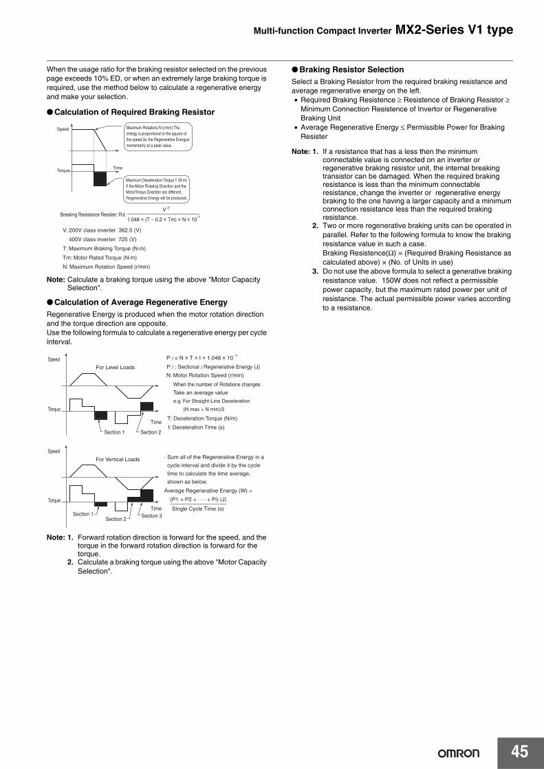
Multi-function Compact Inverter MX2-Series V1 type
45
When the usage ratio for the braking resistor selected on the previous page exceeds 10% ED, or when an extremely large braking torque is required, use the method below to calculate a regenerative energy and make your selection.
● Calculation of Required Braking Resistor
Note: Calculate a braking torque using the above "Motor Capacity Selection".
● Calculation of Average Regenerative EnergyRegenerative Energy is produced when the motor rotation direction and the torque direction are opposite.Use the following formula to calculate a regenerative energy per cycle interval.
Note: 1. Forward rotation direction is forward for the speed, and the torque in the forward rotation direction is forward for the torque.
2. Calculate a braking torque using the above "Motor Capacity Selection".
● Braking Resistor SelectionSelect a Braking Resistor from the required braking resistance and average regenerative energy on the left.• Required Braking Resistence ≥ Resistence of Braking Resistor ≥
Minimum Connection Resistence of Invertor or Regenerative Braking Unit
• Average Regenerative Energy ≤ Permissible Power for Braking Resister
Note: 1. If a resistance that has a less then the minimum connectable value is connected on an inverter or regenerative braking resistor unit, the internal breaking transistor can be damaged. When the required braking resistance is less than the minimum connectable resistance, change the inverter or regenerative energy braking to the one having a larger capacity and a minimum connection resistance less than the required braking resistance.
2. Two or more regenerative braking units can be operated in parallel. Refer to the following formula to know the braking resistance value in such a case.Braking Resistence(Ω) = (Required Braking Resistance as calculated above) × (No. of Units in use)
3. Do not use the above formula to select a generative braking resistance value. 150W does not reflect a permissible power capacity, but the maximum rated power per unit of resistance. The actual permissible power varies according to a resistance.
1.048 × (T – 0.2 × Tm) × N × 10
V: 200V class inverter 362.5 (V)
400V class inverter 725 (V)
T: Maximum Braking Torque (N·m)
Tm: Motor Rated Torque (N·m)
N: Maximum Rotation Speed (r/min)
Breaking Resistance Resister: R≤V
TimeTorque
Speed
-1
2
Maximum Deceleration Torque T (N·m) If the Motor Rotating Direction and the MotorTorque Direction are different, Regenerative Energy will be produced.
Maximum Rotations N (r/min) The energy is proportional to the square of the speed,So the Regenerative Energyis momentarily at a peak value.
P = N × T × t × 1.048 × 10
Time
Section 1
Section 1
Section 2
Section 2Section 3
Time
For Level Loads
For Vertical Loads
Torque
Torque
Speed
Speed
–1
When the number of Rotations changes
Take an average value
e.g. For Straight-Line Deceleration
(N max + N min)/2
N: Motor Rotation Speed (r/min)
t: Deceleration Time (s)
· Sum all of the Regenerative Energy in a
cycle interval and divide it by the cycle
time to calculate the time average,
shown as below.
Average Regenerative Energy (W) =
T: Deceleration Torque (N/m)
P : Sectional Regenerative Energy (J)
(P1 + P2 + · · · + Pi) (J)
Single Cycle Time (s)
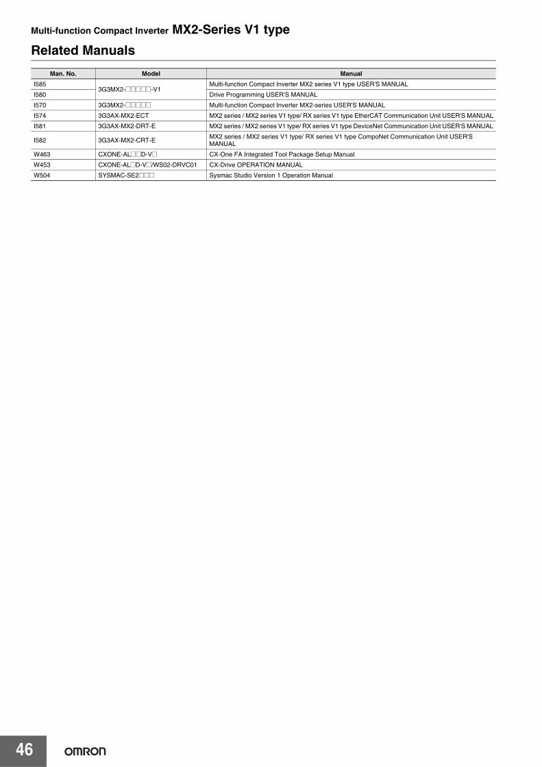
Multi-function Compact Inverter MX2-Series V1 type
46
Related ManualsMan. No. Model Manual
I5853G3MX2-@@@@@-V1
Multi-function Compact Inverter MX2 series V1 type USER'S MANUAL
I580 Drive Programming USER'S MANUAL
I570 3G3MX2-@@@@@ Multi-function Compact Inverter MX2-series USER'S MANUAL
I574 3G3AX-MX2-ECT MX2 series / MX2 series V1 type/ RX series V1 type EtherCAT Communication Unit USER'S MANUAL
I581 3G3AX-MX2-DRT-E MX2 series / MX2 series V1 type/ RX series V1 type DeviceNet Communication Unit USER'S MANUAL
I582 3G3AX-MX2-CRT-EMX2 series / MX2 series V1 type/ RX series V1 type CompoNet Communication Unit USER'S MANUAL
W463 CXONE-AL@@D-V@ CX-One FA Integrated Tool Package Setup Manual
W453 CXONE-AL@D-V@/WS02-DRVC01 CX-Drive OPERATION MANUAL
W504 SYSMAC-SE2@@@ Sysmac Studio Version 1 Operation Manual
Terms and Conditions AgreementRead and understand this catalog.
Please read and understand this catalog before purchasing the products. Please consult your OMRON representative if you have any questions or comments.
Warranties.(a) Exclusive Warranty. Omron’s exclusive warranty is that the Products will be free from defects in materials and workmanship
for a period of twelve months from the date of sale by Omron (or such other period expressed in writing by Omron). Omron disclaims all other warranties, express or implied.
(b) Limitations. OMRON MAKES NO WARRANTY OR REPRESENTATION, EXPRESS OR IMPLIED, ABOUT NON-INFRINGEMENT, MERCHANTABILITY OR FITNESS FOR A PARTICULAR PURPOSE OF THE PRODUCTS. BUYER ACKNOWLEDGES THAT IT ALONE HAS DETERMINED THAT THE PRODUCTS WILL SUITABLY MEET THE REQUIREMENTS OF THEIR INTENDED USE.
Omron further disclaims all warranties and responsibility of any type for claims or expenses based on infringement by the Products or otherwise of any intellectual property right. (c) Buyer Remedy. Omron’s sole obligation hereunder shall be, at Omron’s election, to (i) replace (in the form originally shipped with Buyer responsible for labor charges for removal or replacement thereof) the non-complying Product, (ii) repair the non-complying Product, or (iii) repay or credit Buyer an amount equal to the purchase price of the non-complying Product; provided that in no event shall Omron be responsible for warranty, repair, indemnity or any other claims or expenses regarding the Products unless Omron’s analysis confirms that the Products were properly handled, stored, installed and maintained and not subject to contamination, abuse, misuse or inappropriate modification. Return of any Products by Buyer must be approved in writing by Omron before shipment. Omron Companies shall not be liable for the suitability or unsuitability or the results from the use of Products in combination with any electrical or electronic components, circuits, system assemblies or any other materials or substances or environments. Any advice, recommendations or information given orally or in writing, are not to be construed as an amendment or addition to the above warranty.
See http://www.omron.com/global/ or contact your Omron representative for published information.
Limitation on Liability; Etc.OMRON COMPANIES SHALL NOT BE LIABLE FOR SPECIAL, INDIRECT, INCIDENTAL, OR CONSEQUENTIAL DAMAGES, LOSS OF PROFITS OR PRODUCTION OR COMMERCIAL LOSS IN ANY WAY CONNECTED WITH THE PRODUCTS, WHETHER SUCH CLAIM IS BASED IN CONTRACT, WARRANTY, NEGLIGENCE OR STRICT LIABILITY.
Further, in no event shall liability of Omron Companies exceed the individual price of the Product on which liability is asserted.
Suitability of Use.Omron Companies shall not be responsible for conformity with any standards, codes or regulations which apply to the combination of the Product in the Buyer’s application or use of the Product. At Buyer’s request, Omron will provide applicable third party certification documents identifying ratings and limitations of use which apply to the Product. This information by itself is not sufficient for a complete determination of the suitability of the Product in combination with the end product, machine, system, or other application or use. Buyer shall be solely responsible for determining appropriateness of the particular Product with respect to Buyer’s application, product or system. Buyer shall take application responsibility in all cases.
NEVER USE THE PRODUCT FOR AN APPLICATION INVOLVING SERIOUS RISK TO LIFE OR PROPERTY OR IN LARGE QUANTITIES WITHOUT ENSURING THAT THE SYSTEM AS A WHOLE HAS BEEN DESIGNED TO ADDRESS THE RISKS, AND THAT THE OMRON PRODUCT(S) IS PROPERLY RATED AND INSTALLED FOR THE INTENDED USE WITHIN THE OVERALL EQUIPMENT OR SYSTEM.
Programmable Products.Omron Companies shall not be responsible for the user’s programming of a programmable Product, or any consequence thereof.
Performance Data.Data presented in Omron Company websites, catalogs and other materials is provided as a guide for the user in determining suitability and does not constitute a warranty. It may represent the result of Omron’s test conditions, and the user must correlate it to actual application requirements. Actual performance is subject to the Omron’s Warranty and Limitations of Liability.
Change in Specifications.Product specifications and accessories may be changed at any time based on improvements and other reasons. It is our practice to change part numbers when published ratings or features are changed, or when significant construction changes are made. However, some specifications of the Product may be changed without any notice. When in doubt, special part numbers may be assigned to fix or establish key specifications for your application. Please consult with your Omron’s representative at any time to confirm actual specifications of purchased Product.
Errors and Omissions.Information presented by Omron Companies has been checked and is believed to be accurate; however, no responsibility is assumed for clerical, typographical or proofreading errors or omissions.

Authorized Distributor:
In the interest of product improvement, specifications are subject to change without notice.
Cat. No. I920-E1-02 0714(0909)
© OMRON Corporation 2009-2014 All Rights Reserved.
OMRON Corporation Industrial Automation Company
OMRON ELECTRONICS LLC2895 Greenspoint Parkway, Suite 200 Hoffman Estates, IL 60169 U.S.ATel: (1) 847-843-7900/Fax: (1) 847-843-7787
Regional HeadquartersOMRON EUROPE B.V.Wegalaan 67-69, 2132 JD HoofddorpThe NetherlandsTel: (31)2356-81-300/Fax: (31)2356-81-388
Contact: www.ia.omron.comTokyo, JAPAN
OMRON ASIA PACIFIC PTE. LTD.No. 438A Alexandra Road # 05-05/08 (Lobby 2), Alexandra Technopark, Singapore 119967Tel: (65) 6835-3011/Fax: (65) 6835-2711
OMRON (CHINA) CO., LTD.Room 2211, Bank of China Tower, 200 Yin Cheng Zhong Road, PuDong New Area, Shanghai, 200120, ChinaTel: (86) 21-5037-2222/Fax: (86) 21-5037-2200
Note: Do not use this document to operate the Unit.
CSM_14_6_0718


![MX2 sync [final].vp](https://img.pdfslide.us/doc/110x75/589f00e91a28aba94a8c2cf1/mx2-sync-finalvp.jpg)