Embed Size (px)
Citation preview
MULTI-ENTRANCES SECURITY DOOR SYSTEM
YASOTHA A/P PADMANATHAN
This thesis is submitted as partial fulfillment of the requirements for the award of the
Bachelor of Electrical Engineering (Hons.) (Electronics)
Faculty of Electrical & Electronics Engineering
Universiti Malaysia Pahang
JUNE, 2012
vi
ABSTRACT
Over the years, several security measures have been employed to combat the
menace of insecurity of lives and property. This is done by preventing unauthorised
entrance into buildings through entrance doors using conventional and electronic
locks or discrete access code. Thus, the main idea in this project is to design a
database security system that allows only authorised user to enter the premises. There
are two entry point with each using different technologies; RFID & keypad. Once the
user’s identification is verified, the door is unlocked by using EDL (electronic door
lock) and all the information such as user ID, date and time are stored in central
office. The communication between the entrance points with central office by means
of Zigbee wireless technology.
vii
ABSTRAK
Sejak beberapa tahun kebelakangan ini, beberapa langkah-langkah
keselamatan yang telah digunakan untuk memerangi ancaman yang mengancam
keselamatan nyawa dan harta benda. Ini dilakukan dengan menghalang kemasukan
ke dalam bangunan dengan menggunakan kunci konvensional dan elektronik atau
kod akses diskret. Oleh itu, idea utama dalam projek ini adalah untuk merekabentuk
satu sistem pangkalan data keselamatan yang membolehkan hanya pengguna yang
sah sahaja boleh memasuki premis. Terdapat dua pintu masuk dengan setiap pintu
menggunakan teknologi yang berbeza; RFID & pad kekunci. Selepas
pengenalpastian pengguna disahkan, pintu dibuka dengan menggunakan EDL (kunci
pintu elektronik) dan semua maklumat seperti ID pengguna, tarikh dan masa yang
disimpan di pejabat pusat. Komunikasi antara pintu masuk dengan pejabat pusat
adalah dengan menggunakan teknologi “wireless” ZigBee.
viii
TABLE OF CONTENTS
CHAPTER TITLE PAGE
TITLE PAGE i
SUPERVISOR’S DECLARATION ii
STUDENT’S DECLARATION iii
DEDICATION iv
ACKNOWLEDGEMENT v
ABSTRACT vi
ABSTRAK vii
TABLE OF CONTENTS viii
LIST OF FIGURES xii
LIST OF TABLES xiv
LIST OF ABBREVIATION xv
LIST OF APPENDIXES xvi
1 INTRODUCTION 1
1.1 Overview 1
1.2 Wireless Technologies 3
1.2.1 Radio Frequency Identification (RFID) 3
1.2.2 Zigbee 4
1.3 Problem Statement 5
1.4 Objectives 5
1.5 Scope of project 5
1.6 Thesis outline 6
ix
2 LITERATURE REVIEW 7
2.1 Introduction 7
2.2 System Applications Conducted by Researchers 8
2.2.1 The Design and Implementation of
Intelligent Campus Security Tracking
System Based on RFID and ZigBee.
8
2.2.2 Scalable ZigBee-Based Smart
Authentication and Access Control System
Design Using XMOS Programmable Chips.
10
2.2.3 Wireless Networked Security System
Based on ZigBee Technology.
11
2.24 Building a Smart University using RFID
Technology.
12
2.2.5 Implementation of ZigBee-GSM based
Home Security Monitoring and Remote
Control system.
13
2.2.6 Design of RFID Proximity Security Door
Lock.
14
2.2.7 Design of Dynamic RFID System using
89C51 Microcontroller based Embedded
System for Effective Supply Chain
Management.
15
2.2.8 Microcontroller Based Home Automation
System with Security.
16
2.2.9 A Scalable Intelligent Room Based on
Wireless Sensor Networks and RFIDs.
16
2.2.10 Research on Application of RFID System
with 2nd-Generation ID card Based on
ZigBee Wireless Network.
17
3 HARDWARE IMPLEMENTATION 18
3.1 Introduction 18
x
3.2 System board of the Multi-entrances security door
System.
19
3.3 The system operation 20
3.4 Hardware 22
3.4.1 Microcontroller PIC18F4525 22
3.4.2 Power Supply Module 23
3.4.3 Reset Module 24
3.4.4 Liquid Crystal Display 25
3.4.5 Serial Communication Module 26
3.4.6 RFID Reader and Tag 27
3.4.7 Xbee Module 29
3.4.7.1 Xbee Module vs XbeePro
Module
29
3.4.7.2 Uart 31
3.4.7.3 Xbee PRO Transmitter
Ciruit
31
3.4.7.4 Xbee PRO Receiver Circuit 32
3.4.8 Keypad Module 33
4 SOFTWARE IMPLEMENTATION 34
4.1 Introduction 34
4.2 The C language 35
4.3 The C compiler 36
4.4 Programming Coding 37
4.4.1 LCD display 37
4.4.2 Receive data from RFID reader 38
4.4.3 Password coding 39
4.5 Microsoft Visual Basic 40
5 RESULTS AND DISCUSSIONS 41
5.1 Introduction 41
xi
5.2 Software Simulation Results 42
5.2.1 Simulation testing for LCD 42
5.2.2 Simulation testing for RFID reader 43
5.2.3 Simulation testing for keypad 44
5.2.4 Simulation for overall system 46
5.3 Hardware result of the system 51
5.4 Discussion 57
6 CONCLUSION 58
6.1 Conclusion 58
6.2 Recommendation 59
6.3 Costing and Commercialization 60
REFERENCES 61
APPENDIX A 62
APPENDIX B 63
APPENDIX C 64
xii
LIST OF FIGURES
FIGURE NO. TITLE PAGE
2.1 System architecture designed by Xiaokang Li and Li Gao 9
2.2
Model system proposed by Wael Hosny Fouad Aly,
Haytham Aboulabbas M., Moustafa H. Aly, Hossam
Eldin Moustafa
11
2.3 Block diagram of the system 12
2.4 Block diagram and circuit connection of the system. 13
2.5 Block diagram of the system 14
2.6 Block diagram of the system. 17
3.1 Basic Block Diagram of the multi-entrances door security
system using wireless technology. 19
3.2 Flow chart of the multi-entrances security door system 21
3.3 Pin layout of PIC18F4525 23
3.4 Power circuit 23
3.5 Reset circuit 24
3.6 LCD Module 25
3.7 Serial communication module 26
3.8 12 byte ID packet data 27
3.9 RFID Reader and Female RS232 cable with USB and
RJ11 28
3.10 Mechanical drawing of XBee 30
3.11 Mechanical drawing of XBee Pro 30
3.12 XBee Pro Transmitter Module 31
3.13 XBee Pro Receiver Module 32
xiii
3.14 Keypad pin configuration 33
4.1 PICkit 2 Programmer Interface 36
4.2 LCD display source code 37
4.3 C Code to Receive RFID Data 38
4.4 C code for password detection 39
5.1 LCD testing result 42
5.2 RFID reader testing 43
5.3 Keypad testing 44
5.4 Keypad testing 45
5.5 Keypad testing 45
5.6 “WELCOME” display when system is initialized 46
5.7 Instruction message to tag the ID card 47
5.8 Displaying user’s ID card number 48
5.9 Displaying user’s name 48
5.10 Password verification 49
5.11 Activation to the door access 50
5.12 Display “Place the card” message 51
5.13 Display User ID number 51
5.14 Display password 52
5.15 Display “Open Door” 52
5.16 Wrong password 53
5.17 LCD displays “Error door” 53
5.18 Zigbee connected to PC is connected at COM port 12 54
5.19 Administrator entrance 54
5.20 Access to Employee data & recorded attendance data 55
5.21 Employee data saved in PC 55
5.22 Recorded data of who entered the premises. 56
xiv
LIST OF TABLES
TABLE NO. TITLE PAGE
3.1 Specifications of the XBee /XBee‐PRO ZNet 2.5
OEM RF Module 30
xv
LIST OF ABBREVIATIONS
RFID - Radio Frequency Identification
LCD - Liquid Crystal Display
MHz - Megahertz
GHz - Gigahertz
RF - Radio frequency
UART - Universal Asynchronous Receive Transmit
PIC - Programmable Intelligent Computer
V - Volts
xvi
LIST OF APPENDIXES
APPENDIX TITLE PAGE
A Circuit – Host system ( Entrance 1) 59
B Circuit – Host system ( Entrance 2) 60
C Circuit – Secondary system 61
CHAPTER 1
INTRODUCTION
1.1 OVERVIEW
Security and safety have always been of prime concern to every individual or
an organization. Safety is the guarantee for the most essential existent of human
beings. A security system is necessary for a building or an area to guarantee the
safety of the residents and property. The security system has gone through single-
route monitor system, control loop monitor system, and processor plus multimedia
monitor system eras in the past twenty years. The digital monitor system which used
abroad today is the fourth era production of the security system.
It’s very annoying that all of the security systems show many shortcomings
such as the signals transmitted through cable network, wiring network is a severe
time-consuming and high-load work, and it always blocks the progress of the
engineering, the information can be watched only in monitoring chamber. It’s very
difficult to extend system, because the wire connection is fixed, high energy-
consuming system and the after-effect is very serious if the cable be cut.
No matter if the building is a corporate setup, home, a public place or a
factory, it has become imperative to secure it against potential dangers such as theft,
crime, and fire etc. An intelligent system is therefore required which should not only
detect but also pre-empt such hazards. Today it has to be updated with the rapidly
changing technology to ensure vast coverage, remote control, reliability, and real
2
time operation. Deploying wireless technologies for security and control in security
systems offers attractive benefits along with user friendly interface. The
advancements in security and information technologies have led to availability of
many off the shelf products. Unfortunately the conventional solutions such as CCTV
security solutions, IP network video solutions and fire alarm systems are too costly in
terms of deployment and power efficiency; they are application specific, making
them void to provide all in one.
For this reason, the Multi-Entrances Security Door System project is
proposed. This project uses technology such as Radio Frequency Identification and
Zigbee to provide further security system that can be implemented in offices and
home premises.
3
1.2 WIRELESS TECHNOLOGIES
Radio Frequency Identification (RFID) and Zigbee are two wireless
technologies that have each developed hosts of applications independent of each
other. Each has benefits, with ZigBee supporting advanced sensor networks and
RFID suitable for low-power wireless tracking of people and objects.
1.2.1 Radio Frequency Identification (RFID)
Radio Frequency Identification (RFID) is a new technology that
incorporates the use of electromagnetic or electrostatic coupling in the radio
frequency (RF) portion of the electromagnetic spectrum to uniquely identify an
object, animal, or person. There is a wide research and development in this area
trying to take maximum advantage of this technology, and in coming years many
new applications and research areas will continue to appear. This massive growth in
RFID also brings about some concerns, mainly the security and privacy of those who
work with or use tags in their everyday life. RFID technology is much more secure
compared to other networks.
RFID technology consist of RFID reader and RFID tags. RFID tags are also
called RFID transponders and they are divided into passive and active RFID tags. In
this project passive tags are being used. This technology allows the system nodes or
tags to exchange data via radio frequency signal communication. After receiving a
radio signal, the tags process this information in order to answer back the basic data
required for identifying the tag uniquely. This data is processed in the reader side
with the help of software tools such as an auxiliary database or some other
communication system. Some of the most popular applications of the RFID
technology include, object and good authentication, access control for vehicles and
humans, race timing, animal identification, product tracking and inventory systems,
etc.
4
1.2.2 Zigbee
ZigBee is one of the typical short-range wireless communication
technologies, which has been widely used in a certain application areas including the
family network, control network, mobile phones and other mobile terminals in
foreign countries. ZigBee is a software standard that sits on top of the IEEE802.15.4
low data rate wireless standard. The ZigBee (IEEE 802.15.4) is a new technology
that permits the implementation of Wireless Personal Area Networks (WPAN). It is
very suitable for wireless sensor networks due to the very low power consumption.
The selection of the Radio Frequency (RF) communication modules used for the
wireless transmission part in this project is based on several criteria. They are range
of communication, power consumption, ease of integration and the cost. So, for this
project the XBee PRO wireless modules is chosen which conform to the IEEE
802.15.4 standard.
This system uses ZigBee to build transmission network, which is used for the
transmission of sensor data, and uses customized wireless transmission protocol,
which is designed based on simplicity and reliability. In the protocol, considering
simplifying microcontroller functions of RFID & ZigBee node and reducing system
cost, the wireless transmission protocol mainly achieves the capabilities of error
checking, data framing, conflict mechanisms such as retransmission, etc.
5
1.3 PROBLEM STATEMENT
The existing security systems show many shortcomings such as difficult to
extend and severe time-consuming because it is based on wiring network technology.
For a wired network, certain levels of security are maintained since access to the
physical medium is restricted to the devices physically connected to the network. It is
very difficult to extend the system, because the wire connection is fixed. In additon,
there are also insecurity in system identification due to the information can be
watched only in monitoring chamber. Failure of keeping or tracking the database
leads to increasing theft or insecurity to the lives and properties.
1.4 OBJECTIVES
To develop and design a secure door security system using various form of
technology such as Radio frequency Identification (RFID) with a secure and effective Zigbee
wireless transmission of data.
1.5 SCOPE OF PROJECT
The scope of this project is:
Develop at least 2 different type of user identification such as using RadioFrequency Identification (RFID) & keypad.
Use wireless transmission technology such as RF & Zigbee for nodescommunication.
Develop a database at master node for analysis.
6
1.6 THESIS OUTLINE
Multi-entrances Security Door System project’s final thesis is a combination of 6
chapters that contains and elaborates specific topics such as the Introduction, Literature
Review, Hardware Implementation, Software implementation, Result and discussion and
Conclusion.
Chapter 1 is the Introduction of the project. The explanation for the project will
be given in a general term. The objectives of the project will be elaborated. It is followed
by the explanation in the scope of project and also the problem statements.
Chapter 2 is the Literature review for the development of multi-entrances door
security system. This chapter describes the literature review of the project elaborately.
Explanation will be focused on security system related researched and based on theory
and conceptual ideas. Some literature reviews of current existing projects based on
security system are also be discussed.
Chapter 3 is the Hardware design.. The explanation gives according to the
function in the board. Flow of the project and how it is executed is explained in detail.
This section gives explanation more towards on technical part of it.
Chapter 4 is the Software implementation part. Software development of the
project is discussed here. Software used and how it is executed will be discussed here.
Chapter 5 discussed about results of testing conducted for the project. All the
testing results are shown here with appropriate explanation.
Chapter 6 discusses the conclusion and further development of the project. This
chapter also discussed about the total costing involved and potential of this project for
commercialization.
CHAPTER 2
LITERATURE REVIEW
2.1 INTRODUCTION
Security is the condition of being protected against danger, loss, and
criminals. In the general sense, security is a concept similar to safety. The slight
difference between the two is an added importance on being protected outside threats
or dangers. Individuals or actions that go or act against the general rules of protection
are responsible for the breach of security.
Security has to be compared and contrasted with other related concepts:
Safety, continuity, reliability. The key difference between security and reliability is
that security must take into account the actions of people attempting to cause
destruction. There is an immense literature on the analysis and categorization of
security.
In this chapter, the review of literature is explained briefly with the guidance
of the existing projects conducted by researchers for the development of the project,
multi-entrances security door system. In literature review, the technologies such as
Radio Frequency Identification (RFID) and Xbee Pro wireless technology that is
used in this multi-entrances security door system is further discussed.
8
2.2 SYSTEM APPLICATIONS CONDUCTED BY RESEARCHERS
Over the years, security system is implemented in various places. A security
measure plays an important role in daily life. Some of the researchers have
conducted and successfully developed various types of security systems using
different technologies.
2.2.1 The Design and Implementation of Intelligent Campus Security
Tracking System Based on RFID and ZigBee
The project [1] is designed by Xiaokang Li and Li Gao and it is based on
RFID and ZigBee wireless technology. The intelligent campus security tracking
system uses physical methods and electronic technology, automatically detects theft
in monitoring areas, generates alarm signals, and tracks targets through the detection
point of RFID.
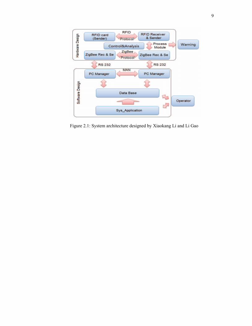
Figure 2.1 shows the flow of the operating system for the project. RFID &
ZigBee nodes sense the RFID (master / slave) labels and it then send information in
the labels to the ZigBee network real time, which is then transferred to the PC nodes.
PC checks the label information in the database, when master label and slave label
match or only master label appears; the system recognizes it as legal input. But when
only slave label appears or master label and slave label don’t match, the system
recognize it as illegal input, then step to is proceeded. Position changes of RFID
(slave) the tags are recorded, slave tags are tracked, and warning are shown at PC
nodes. Then the database is keep tracked, looking for the owner of items and
confirming information is sent to the owner through the system. When the owner
logins WEB to search for items, he can see the real-time location of his valuables
according to the hints. After confirmation, the valuables will be stopped at the
entrance guard. As for false information, the owner can cancel this warning.
9
Figure 2.1: System architecture designed by Xiaokang Li and Li Gao
10
2.2.2 Scalable ZigBee-Based Smart Authentication and Access Control System
Design Using XMOS Programmable Chips.
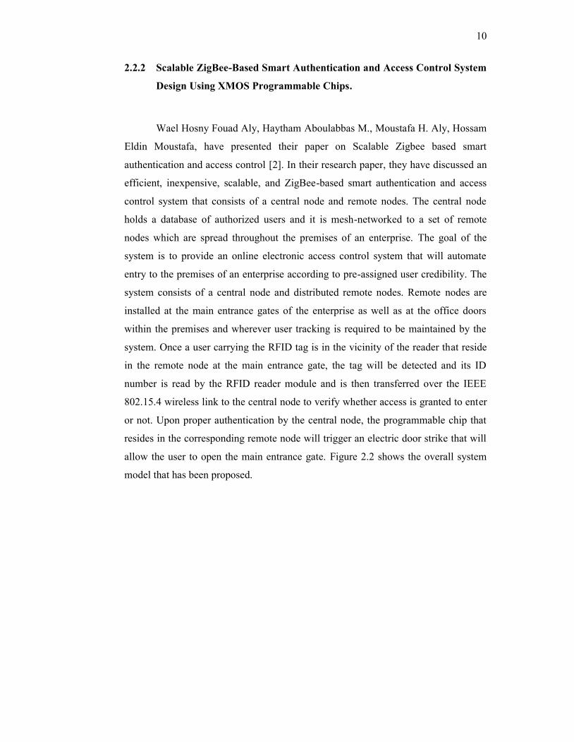
Wael Hosny Fouad Aly, Haytham Aboulabbas M., Moustafa H. Aly, Hossam
Eldin Moustafa, have presented their paper on Scalable Zigbee based smart
authentication and access control [2]. In their research paper, they have discussed an
efficient, inexpensive, scalable, and ZigBee-based smart authentication and access
control system that consists of a central node and remote nodes. The central node
holds a database of authorized users and it is mesh-networked to a set of remote
nodes which are spread throughout the premises of an enterprise. The goal of the
system is to provide an online electronic access control system that will automate
entry to the premises of an enterprise according to pre-assigned user credibility. The
system consists of a central node and distributed remote nodes. Remote nodes are
installed at the main entrance gates of the enterprise as well as at the office doors
within the premises and wherever user tracking is required to be maintained by the
system. Once a user carrying the RFID tag is in the vicinity of the reader that reside
in the remote node at the main entrance gate, the tag will be detected and its ID
number is read by the RFID reader module and is then transferred over the IEEE
802.15.4 wireless link to the central node to verify whether access is granted to enter
or not. Upon proper authentication by the central node, the programmable chip that
resides in the corresponding remote node will trigger an electric door strike that will
allow the user to open the main entrance gate. Figure 2.2 shows the overall system
model that has been proposed.
11
Figure 2.2: Model system proposed by Wael Hosny Fouad Aly, Haytham
Aboulabbas M., Moustafa H. Aly, Hossam Eldin Moustafa
2.2.3 Wireless Networked Security System Based on ZigBee Technology.
In [3], present a wireless networked security system based on ZigBee
technology. The system adopts hybrid topology structure based on cluster, which
consists of many micro-sensor nodes, network coordinator nodes, network gateway
(router), communication network and monitor centre (computer). For short distance
transmission, the micro-sensor nodes collect data from the monitoring surroundings
and transmit to the gateway using ZigBee communication. For long distance
transmission, from the gateway to the monitor centre, system uses TCP/IP protocol.
The gateway in this system is the protocol conversion used to transform a data
package in ZigBee protocol to TCP/IP protocol before transmitting.
12
2.2.4 Building a Smart University using RFID Technology
In this paper [4], the researchers contemplate present the use of RFID
technology in building a smart university. Prototype is developed considering major
use cases involved in a smart university. The system covers maintaining attendance
record, switching control of electrical items and security locks of rooms. Results
show that consumption of energy and object tracking time is decreased while
security of rooms and credibility of attendance record are increased. ZigBee is
selected for this research due to its low cost, long communication range and low
power consumption.
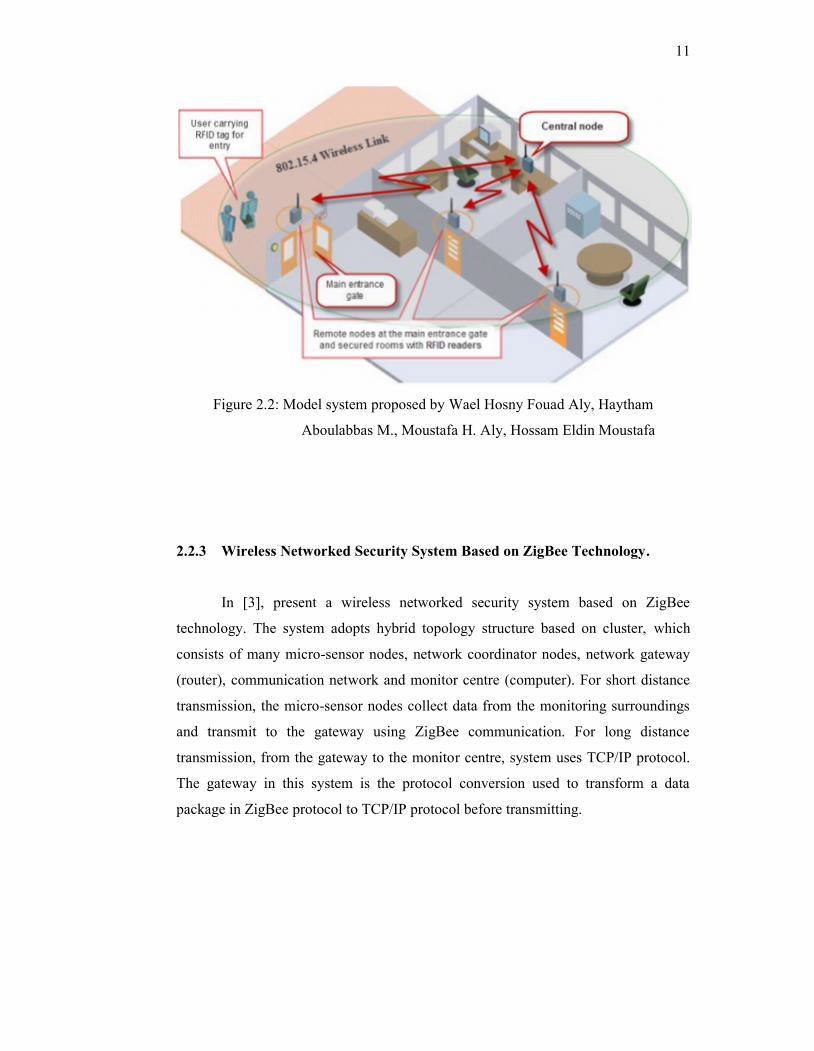
System is working as follows: First Reader detects RFID card and forward
that ID to microcontroller. Microcontroller authenticates the ID and generates a
specific number (3 byte code) against that ID. This specific number is then
forwarded to the ZigBee transceiver via serial link from where it is broadcasted to
receiving nodes. One of the receiving nodes is the database server where attendance
record is managed. At the same time control circuit node receives the broadcast and
automates the office equipments based on that specific profile. The profiles can be
modified from the server as they are stored in NVRAM. Figure 2.3 shows the block
diagram of the system.
Figure 2.3: Block diagram of the system
13
2.2.5 Implementation of ZigBee-GSM based Home Security Monitoring and
Remote Control system.
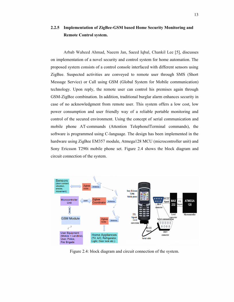
Arbab Waheed Ahmad, Naeem Jan, Saeed Iqbal, Chankil Lee [5], discusses
on implementation of a novel security and control system for home automation. The
proposed system consists of a control console interfaced with different sensors using
ZigBee. Suspected activities are conveyed to remote user through SMS (Short
Message Service) or Call using GSM (Global System for Mobile communication)
technology. Upon reply, the remote user can control his premises again through
GSM-ZigBee combination. In addition, traditional burglar alarm enhances security in
case of no acknowledgment from remote user. This system offers a low cost, low
power consumption and user friendly way of a reliable portable monitoring and
control of the secured environment. Using the concept of serial communication and
mobile phone AT-commands (Attention TelephonelTerminal commands), the
software is programmed using C-Ianguage. The design has been implemented in the
hardware using ZigBee EM357 module, Atmega128 MCU (microcontroller unit) and
Sony Ericsson T290i mobile phone set. Figure 2.4 shows the block diagram and
circuit connection of the system.
Figure 2.4: block diagram and circuit connection of the system.