Embed Size (px)
Citation preview
Multi Engine TrainingTecnam P2006T
CHAPTER 1
Multi-Engine AerodynamicsAt normal cruise the thrust vector of each engine, is through the propeller hub.
Aerodynamic Effects of an Engine FailureWhen an engine failure occurs in a multi-engine aircraft, asymmetric thrust and drag produce the following simultaneous effects on the aircraft’s axes of rotation :
• Pitch down along the lateral axis – loss of accelerated slipstream over the horizontal stabilizer produces less negative lift.
• Roll toward the INOP engine along the longitudinal axis – wing produces less lift on side of failed engine due to loss of accelerated slipstream
• Yaw toward the INOP engine along the vertical axis – loss of thrust and increased drag from the wind milling propeller.
To compensate for these effects, a pilot must add additional back pressure, deflect the ailerons into theoperating engine, and apply rudder pressure on the side of the operating engine.
What does this all do to the LIFT vs. DRAG and PERFORMANCE profile of the aircraft?
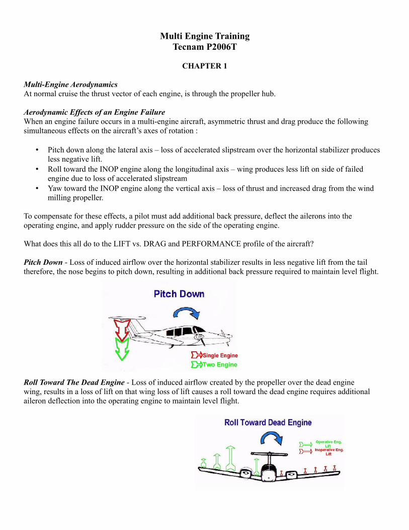
Pitch Down - Loss of induced airflow over the horizontal stabilizer results in less negative lift from the tail therefore, the nose begins to pitch down, resulting in additional back pressure required to maintain level flight.
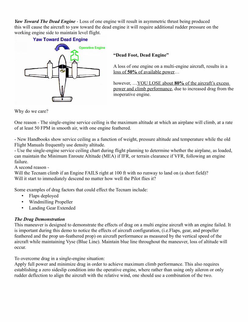
Roll Toward The Dead Engine - Loss of induced airflow created by the propeller over the dead enginewing, results in a loss of lift on that wing loss of lift causes a roll toward the dead engine requires additional aileron deflection into the operating engine to maintain level flight.
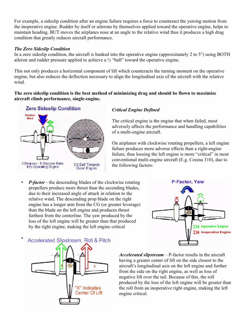
Yaw Toward The Dead Engine - Loss of one engine will result in asymmetric thrust being produced this will cause the aircraft to yaw toward the dead engine it will require additional rudder pressure on the working engine side to maintain level flight.
“Dead Foot, Dead Engine”
A loss of one engine on a multi-engine aircraft, results in a loss of 50% of available power…
however, …YOU LOSE about 80% of the aircraft’s excess power and climb performance, due to increased drag from theinoperative engine.
Why do we care?
One reason - The single-engine service ceiling is the maximum altitude at which an airplane will climb, at a rate of at least 50 FPM in smooth air, with one engine feathered.
- New Handbooks show service ceiling as a function of weight, pressure altitude and temperature while the old Flight Manuals frequently use density altitude.- Use the single-engine service ceiling chart during flight planning to determine whether the airplane, as loaded, can maintain the Minimum Enroute Altitude (MEA) if IFR, or terrain clearance if VFR, following an engine failure.A second reason - Will the Tecnam climb if an Engine FAILS right at 100 ft with no runway to land on (a short field)?Will it start to immediately descend no matter how well the Pilot flies it?
Some examples of drag factors that could effect the Tecnam include:• Flaps deployed• Windmilling Propeller• Landing Gear Extended
The Drag DemonstrationThis maneuver is designed to demonstrate the effects of drag on a multi engine aircraft with an engine failed. It is important during this demo to notice the effects of aircraft configuration, (i.e.Flaps, gear, and propeller feathered and the prop un-feathered prop) on aircraft performance as measured by the vertical speed of the aircraft while maintaining Vyse (Blue Line). Maintain blue line throughout the maneuver, loss of altitude will occur.
To overcome drag in a single-engine situation:Apply full power and minimize drag in order to achieve maximum climb performance. This also requires establishing a zero sideslip condition into the operative engine, where rather than using only aileron or only rudder deflection to align the aircraft with the relative wind, one should use a combination of the two.
For example, a sideslip condition after an engine failure requires a force to counteract the yawing motion from the inoperative engine. Rudder by itself or ailerons by themselves applied toward the operative engine, helps to maintain heading, BUT moves the airplanes nose at an angle to the relative wind thus it produces a high drag condition that greatly reduces aircraft performance.
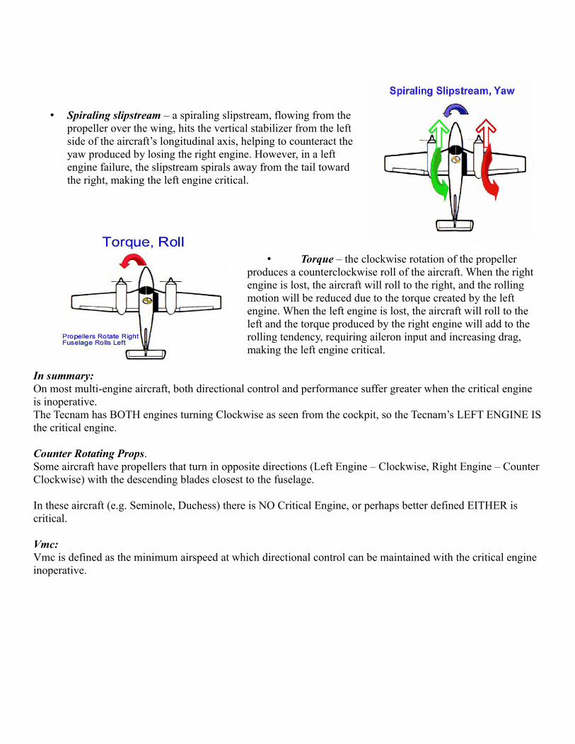
The Zero Sideslip ConditionIn a zero sideslip condition, the aircraft is banked into the operative engine (approximately 2 to 5°) using BOTHaileron and rudder pressure applied to achieve a ½ “ball” toward the operative engine.
This not only produces a horizontal component of lift which counteracts the turning moment on the operative engine, but also reduces the deflection necessary to align the longitudinal axis of the aircraft with the relative wind.
The zero sideslip condition is the best method of minimizing drag and should be flown to maximize aircraft climb performance, single-engine.
Critical Engine Defined
The critical engine is the engine that when failed, most adversely affects the performance and handling capabilities of a multi-engine aircraft.
On airplanes with clockwise rotating propellers, a left engine failure produces more adverse effects than a right-engine failure, thus loosing the left engine is more “critical” in most conventional multi-engine aircraft (E.g. Cessna 310), due to the following factors:
• P-factor - the descending blades of the clockwise rotatingpropellers produce more thrust than the ascending blades,due to their increased angle of attack in relation to therelative wind. The descending prop blade on the rightengine has a longer arm from the CG (or greater leverage)than the blade on the left engine and produces thrustfurthest from the centerline. The yaw produced by theloss of the left engine will be greater than that producedby the right engine, making the left engine critical
•
Accelerated slipstream – P-factor results in the aircraft having a greater center of lift on the side closest to the aircraft’s longitudinal axis on the left engine and further from the side on the right engine, as well as loss of negative lift over the tail. Because of this, the roll produced by the loss of the left engine will be greater thanthe roll from an inoperative right engine, making the left engine critical.
• Spiraling slipstream – a spiraling slipstream, flowing from thepropeller over the wing, hits the vertical stabilizer from the leftside of the aircraft’s longitudinal axis, helping to counteract theyaw produced by losing the right engine. However, in a leftengine failure, the slipstream spirals away from the tail towardthe right, making the left engine critical.
• Torque – the clockwise rotation of the propeller produces a counterclockwise roll of the aircraft. When the right engine is lost, the aircraft will roll to the right, and the rolling motion will be reduced due to the torque created by the left engine. When the left engine is lost, the aircraft will roll to the left and the torque produced by the right engine will add to the rolling tendency, requiring aileron input and increasing drag, making the left engine critical.
In summary:On most multi-engine aircraft, both directional control and performance suffer greater when the critical engine is inoperative.The Tecnam has BOTH engines turning Clockwise as seen from the cockpit, so the Tecnam’s LEFT ENGINE ISthe critical engine.
Counter Rotating Props.Some aircraft have propellers that turn in opposite directions (Left Engine – Clockwise, Right Engine – Counter Clockwise) with the descending blades closest to the fuselage.
In these aircraft (e.g. Seminole, Duchess) there is NO Critical Engine, or perhaps better defined EITHER is critical.
Vmc:Vmc is defined as the minimum airspeed at which directional control can be maintained with the critical engine inoperative.
The FAA sets guidelines for aircraft manufacturers to follow when determining Vmc for each specific aircraft, which is set, based on several conditions set under FAR 23.149.
Any change to one or all of these conditions will either increase or decrease Vmc speed from that indicated on the ASI.What are the guidelines and conditions set by FAR 23.149 that effect Vmc?
10 Factors divided into:• Aircraft Factors
◦ Gear Up (Least Stable)◦ Takeoff Flap and T.O. Trim Settings (Least Stable)◦ Cowl Flaps Open (T.O. Position, Most Critical time)◦ Critical Engine WINDMILLING (Max Drag)◦ Maximum Power on Operating Engine (Max yaw)◦ 5 degree Bank into the Good Engine (Pilot cont.)
• Weight and Balance Factors◦ Aft C.G. (Most unfavorable)◦ Maximum Gross T.O. Weight
• Ambient Factors◦ Standard Conditions (29.92, 15C at Sea Level (@ Max engine power)◦ Out of Ground Effect
Aircraft Factors:1 / 2. Flaps T/O, Gear up, Trim T/O (Least stability) - The extended landing gear and gear doorsproduce a “keel effect”, which reduces yaw, alters the C.G. but the drag from the gear decreases performance. Overall there is a net decrease in Vmc speed with Gear Down. Extended flaps also have a stabilizing effect that reduces Vmc speed, but similarly increase drag, decreasing climb performance.
3. Critical Engine Windmilling (Max drag) - When the propeller of an inoperative engine is left in a low pitch, high RPM position, it produces large amounts of drag due to the large surface area of the blades resisting the relative wind. This produces a “windmilling” effect, which results in a yawing moment into the inoperative engine. However, when the inoperative engine is “feathered”, or moved into a high pitch, low RPM position, drag is minimized…. and Vmc speed is lowered.
4. Maximum Power on Operating Engine (Max yaw) - As the operative engine works toward achievingmaximum power (on takeoff or in climbs), the adverse yaw effect increases toward the inop engine. The pilot must overcome this in order to maintain directional control, by using Rudder and Ailerons. Any condition that increases power on the operating engine will increase Vmc speed, and conditions that decrease power (power reductions, altitude increase, temperature increase, or aging engine) will decrease Vmc.
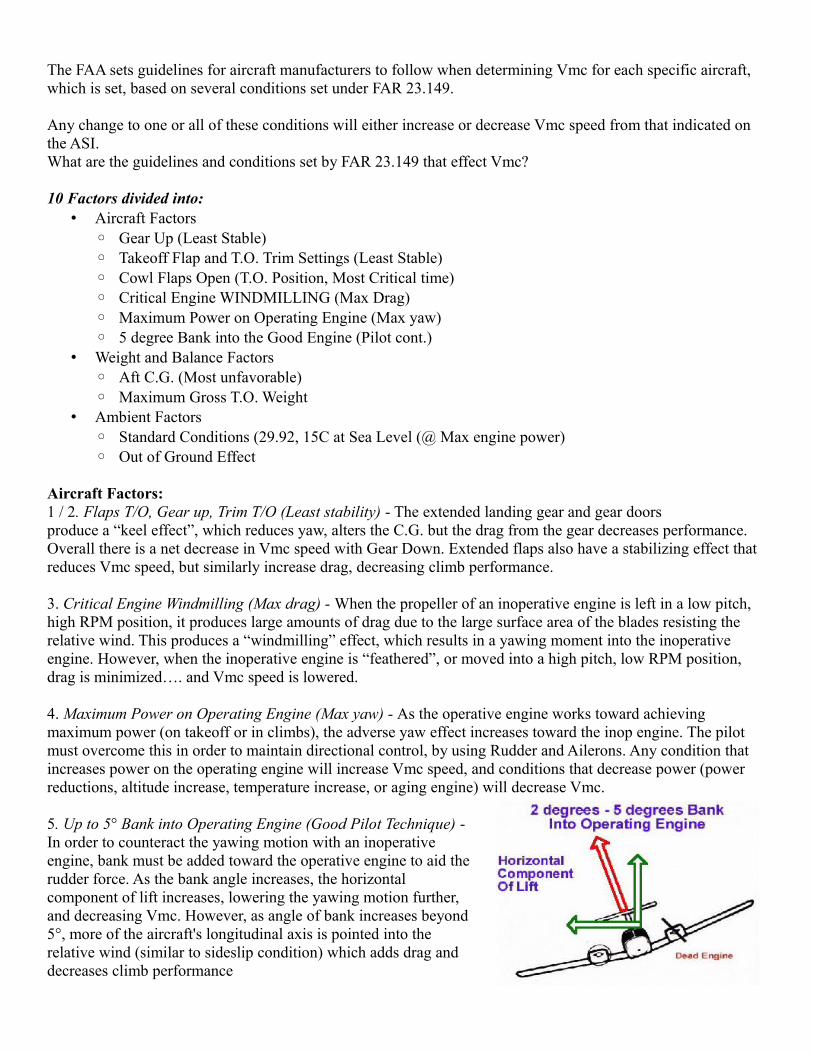
5. Up to 5° Bank into Operating Engine (Good Pilot Technique) -In order to counteract the yawing motion with an inoperativeengine, bank must be added toward the operative engine to aid therudder force. As the bank angle increases, the horizontalcomponent of lift increases, lowering the yawing motion further,and decreasing Vmc. However, as angle of bank increases beyond5°, more of the aircraft's longitudinal axis is pointed into therelative wind (similar to sideslip condition) which adds drag anddecreases climb performance
6. Cowl Flaps – Open - This puts the plane in the most vulnerable configuration, Takeoff, Low, Slow, close to the ground and Cowl Flap and they do have some drag associated with them
Weight and Balance Factors:7. Maximum Gross Weight - In a given angle of bank, the heavier the aircraft, the greater the horizontal component of lift that adds to the rudder force, so at an aircraft's maximum gross weight, the possible horizontalcomponent is greatest and Vmc is decreased. As weight decreases from max gross, the lift component decreases,raising Vmc8. Aft Limit C.G. (Most unfavorable) - As the center of gravity moves forward from aft limits, the moment arm between the rudder and the C. G. lengthens, increasing the leverage of the rudder and the rudder's effectiveness, resulting in a lower Vmc speed
Ambient Factors: 9. Standard Day Conditions at Sea Level (Max engine power) - Standard temperature and pressure conditions (15° C, 29.92” Hg, SL) give the optimum air density for maximum engine performance. An increase in altitude or temperature (decrease in air density) will result in reduced engine performance and propeller efficiency, which decreases the adverse yaw effect. Vmc speed will decrease as density altitude increases
10. Out of Ground Effect - To Reduce the aid to Lift
Engine Inoperative Climb Performance• Climb performance is dependent on excess power to overcome drag.• Drag is a major factor relative to the amount of EXCESS POWER available.• Engine out Procedures are DESIGNED to REDUCE DRAG!
CHAPTER 2
Aircraft SystemsGarmin 950 - G1000 without the Engine Instrument Module - Engine Instruments are located on theRight side of the Instrument Panel.
• LRU = Line Replaceable Units◦ AHRS = Attitude Hdg Reference Unit, Electronic Gyros◦ Magnetometer = Heading Input (Located in the Tail)◦ IAU = Integrated Avionics Unit ◦ ADC = Air Data Computer
Standby Instruments• Standby Attitude Indicator - Electric Driven – Battery Bus• Standby Airspeed Indicator - Ram Air from Left Pitot Tube, Static System• Standby Altimeter - Static System PRIOR to the ADC
Pitot Static System The Pitot Tube has the same function as in a Non Glass Aircraft except,
• Ram Air Inputs go to the Air Data Computer (ADC) and the Standby Instruments(conventional)• The ADC takes the RAM and Static Inputs and converts them to Electronic Signals that the Pilot sees on
the Display.◦ Airspeed, Altitude, Vertical Speed, True Airspeed, OAT◦ Ground Speed input is the GPS
Electrical System• The Tecnam has a 14.2- 14.8 volt DC electrical SYSTEM; a 12-volt, 38-amp hour, 20 hr Runtime, Lead
Acid Gill Teledyne BATTERY; and two 40-amp engine-driven “Generators” (Alternators)• Automatic Voltage regulators are used to maintain constant output from each Generator regardless of
power setting, allowing each to share the total load. They also function as Overvoltage Protection devices
• Voltmeter/Ammeters are located on the Right Side of the Cockpit. ◦ By using a Selector Switch, each Generator can be monitored for the Current being supplied by the
selected Generator• Emergency/Engine Start Battery
◦ Voltmeter is located forward of the Manual Trim Wheel between the seats
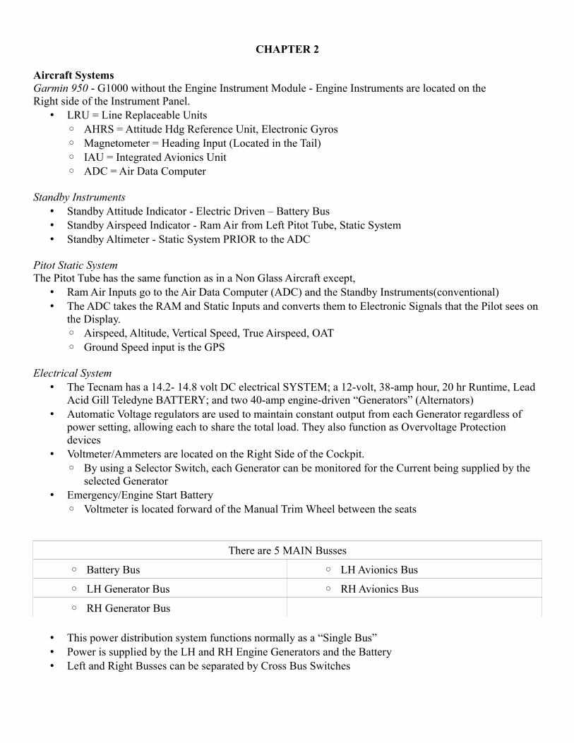
There are 5 MAIN Busses
◦ Battery Bus ◦ LH Avionics Bus
◦ LH Generator Bus ◦ RH Avionics Bus
◦ RH Generator Bus
• This power distribution system functions normally as a “Single Bus”• Power is supplied by the LH and RH Engine Generators and the Battery• Left and Right Busses can be separated by Cross Bus Switches
• Electrical loads are divided based on:◦ Importance◦ Required Power
• Equipment with duplicate functions are connected to separate busses.• The Battery Bus can be powered from 3 sources:
◦ The Battery◦ LH Generator◦ RH Generator
• With TWO independent faults in the supply path, it can stay active
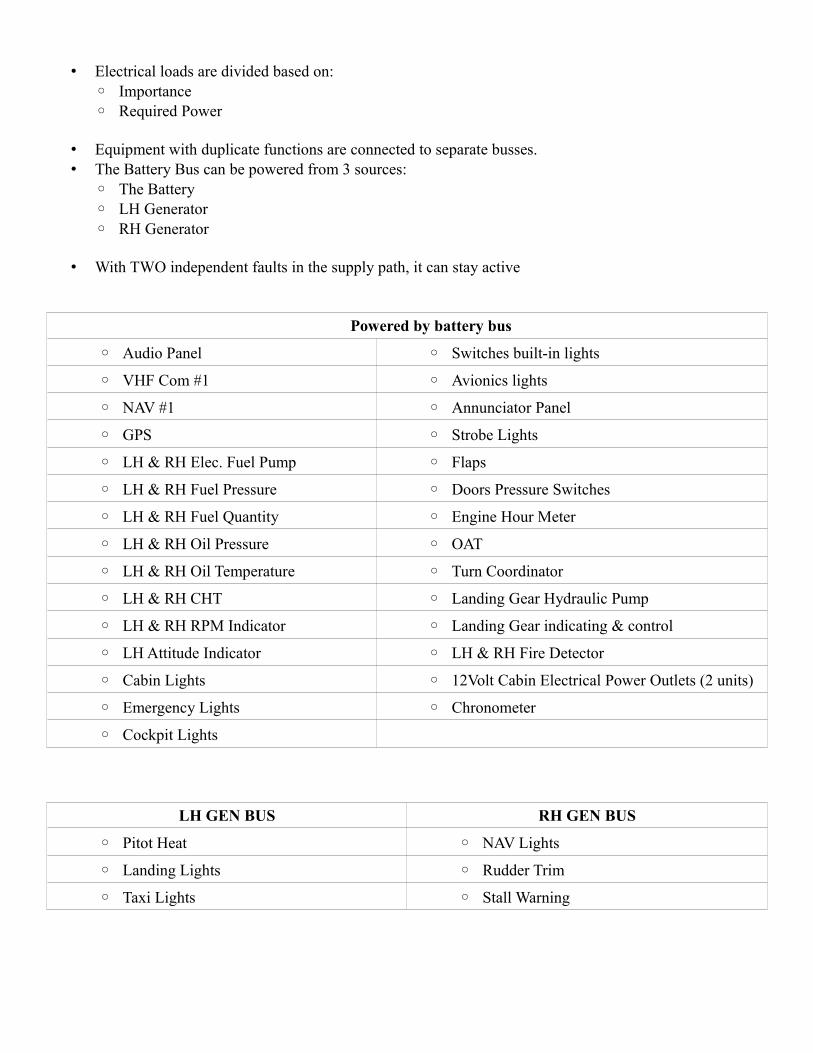
Powered by battery bus
◦ Audio Panel ◦ Switches built-in lights
◦ VHF Com #1 ◦ Avionics lights
◦ NAV #1 ◦ Annunciator Panel
◦ GPS ◦ Strobe Lights
◦ LH & RH Elec. Fuel Pump ◦ Flaps
◦ LH & RH Fuel Pressure ◦ Doors Pressure Switches
◦ LH & RH Fuel Quantity ◦ Engine Hour Meter
◦ LH & RH Oil Pressure ◦ OAT
◦ LH & RH Oil Temperature ◦ Turn Coordinator
◦ LH & RH CHT ◦ Landing Gear Hydraulic Pump
◦ LH & RH RPM Indicator ◦ Landing Gear indicating & control
◦ LH Attitude Indicator ◦ LH & RH Fire Detector
◦ Cabin Lights ◦ 12Volt Cabin Electrical Power Outlets (2 units)
◦ Emergency Lights ◦ Chronometer
◦ Cockpit Lights
LH GEN BUS RH GEN BUS
◦ Pitot Heat ◦ NAV Lights
◦ Landing Lights ◦ Rudder Trim
◦ Taxi Lights ◦ Stall Warning
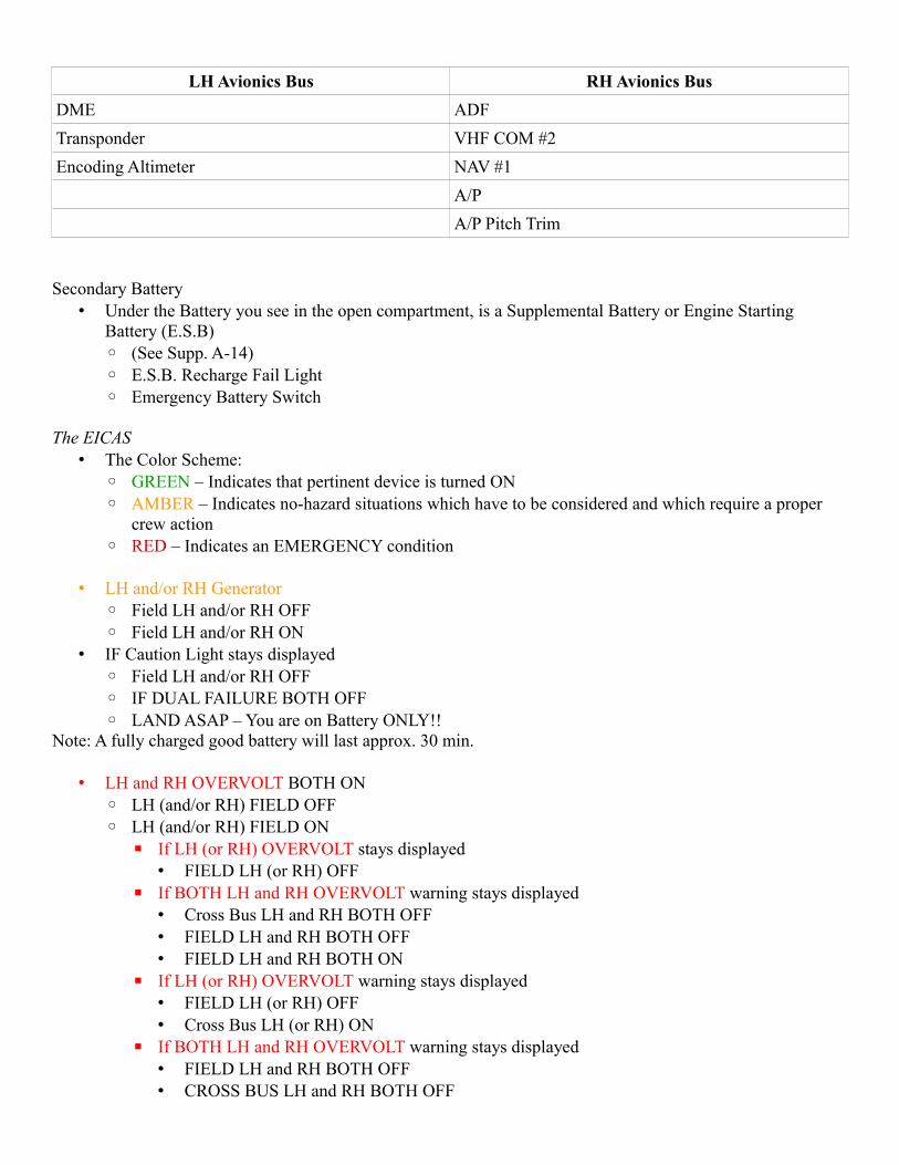
LH Avionics Bus RH Avionics Bus
DME ADF
Transponder VHF COM #2
Encoding Altimeter NAV #1
A/P
A/P Pitch Trim
Secondary Battery• Under the Battery you see in the open compartment, is a Supplemental Battery or Engine Starting
Battery (E.S.B)◦ (See Supp. A-14)◦ E.S.B. Recharge Fail Light◦ Emergency Battery Switch
The EICAS• The Color Scheme:
◦ GREEN – Indicates that pertinent device is turned ON◦ AMBER – Indicates no-hazard situations which have to be considered and which require a proper
crew action◦ RED – Indicates an EMERGENCY condition
• LH and/or RH Generator◦ Field LH and/or RH OFF◦ Field LH and/or RH ON
• IF Caution Light stays displayed◦ Field LH and/or RH OFF◦ IF DUAL FAILURE BOTH OFF◦ LAND ASAP – You are on Battery ONLY!!
Note: A fully charged good battery will last approx. 30 min.
• LH and RH OVERVOLT BOTH ON◦ LH (and/or RH) FIELD OFF◦ LH (and/or RH) FIELD ON
▪ If LH (or RH) OVERVOLT stays displayed• FIELD LH (or RH) OFF
▪ If BOTH LH and RH OVERVOLT warning stays displayed• Cross Bus LH and RH BOTH OFF• FIELD LH and RH BOTH OFF• FIELD LH and RH BOTH ON
▪ If LH (or RH) OVERVOLT warning stays displayed• FIELD LH (or RH) OFF• Cross Bus LH (or RH) ON
▪ If BOTH LH and RH OVERVOLT warning stays displayed• FIELD LH and RH BOTH OFF• CROSS BUS LH and RH BOTH OFF
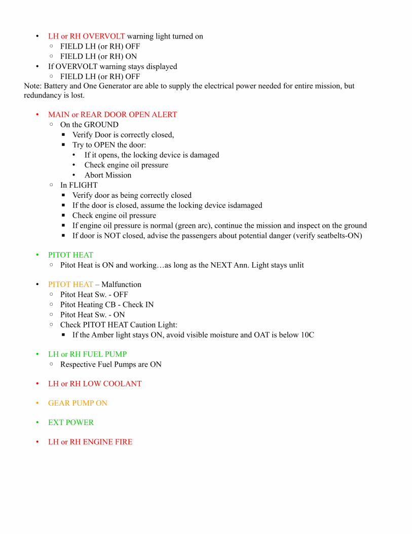
• LH or RH OVERVOLT warning light turned on◦ FIELD LH (or RH) OFF◦ FIELD LH (or RH) ON
• If OVERVOLT warning stays displayed◦ FIELD LH (or RH) OFF
Note: Battery and One Generator are able to supply the electrical power needed for entire mission, but redundancy is lost.
• MAIN or REAR DOOR OPEN ALERT◦ On the GROUND
▪ Verify Door is correctly closed, ▪ Try to OPEN the door:
• If it opens, the locking device is damaged• Check engine oil pressure• Abort Mission
◦ In FLIGHT▪ Verify door as being correctly closed▪ If the door is closed, assume the locking device isdamaged▪ Check engine oil pressure▪ If engine oil pressure is normal (green arc), continue the mission and inspect on the ground▪ If door is NOT closed, advise the passengers about potential danger (verify seatbelts-ON)
• PITOT HEAT ◦ Pitot Heat is ON and working…as long as the NEXT Ann. Light stays unlit
• PITOT HEAT – Malfunction ◦ Pitot Heat Sw. - OFF◦ Pitot Heating CB - Check IN◦ Pitot Heat Sw. - ON ◦ Check PITOT HEAT Caution Light:
▪ If the Amber light stays ON, avoid visible moisture and OAT is below 10C
• LH or RH FUEL PUMP◦ Respective Fuel Pumps are ON
• LH or RH LOW COOLANT
• GEAR PUMP ON
• EXT POWER
• LH or RH ENGINE FIRE
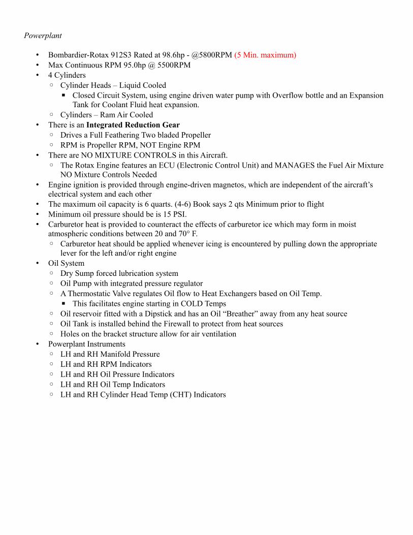
Powerplant
• Bombardier-Rotax 912S3 Rated at 98.6hp - @5800RPM (5 Min. maximum)• Max Continuous RPM 95.0hp @ 5500RPM• 4 Cylinders
◦ Cylinder Heads – Liquid Cooled▪ Closed Circuit System, using engine driven water pump with Overflow bottle and an Expansion
Tank for Coolant Fluid heat expansion.◦ Cylinders – Ram Air Cooled
• There is an Integrated Reduction Gear◦ Drives a Full Feathering Two bladed Propeller◦ RPM is Propeller RPM, NOT Engine RPM
• There are NO MIXTURE CONTROLS in this Aircraft.◦ The Rotax Engine features an ECU (Electronic Control Unit) and MANAGES the Fuel Air Mixture
NO Mixture Controls Needed• Engine ignition is provided through engine-driven magnetos, which are independent of the aircraft’s
electrical system and each other• The maximum oil capacity is 6 quarts. (4-6) Book says 2 qts Minimum prior to flight• Minimum oil pressure should be is 15 PSI.• Carburetor heat is provided to counteract the effects of carburetor ice which may form in moist
atmospheric conditions between 20 and 70° F.◦ Carburetor heat should be applied whenever icing is encountered by pulling down the appropriate
lever for the left and/or right engine• Oil System
◦ Dry Sump forced lubrication system◦ Oil Pump with integrated pressure regulator◦ A Thermostatic Valve regulates Oil flow to Heat Exchangers based on Oil Temp.
▪ This facilitates engine starting in COLD Temps◦ Oil reservoir fitted with a Dipstick and has an Oil “Breather” away from any heat source◦ Oil Tank is installed behind the Firewall to protect from heat sources◦ Holes on the bracket structure allow for air ventilation
• Powerplant Instruments◦ LH and RH Manifold Pressure◦ LH and RH RPM Indicators◦ LH and RH Oil Pressure Indicators◦ LH and RH Oil Temp Indicators◦ LH and RH Cylinder Head Temp (CHT) Indicators
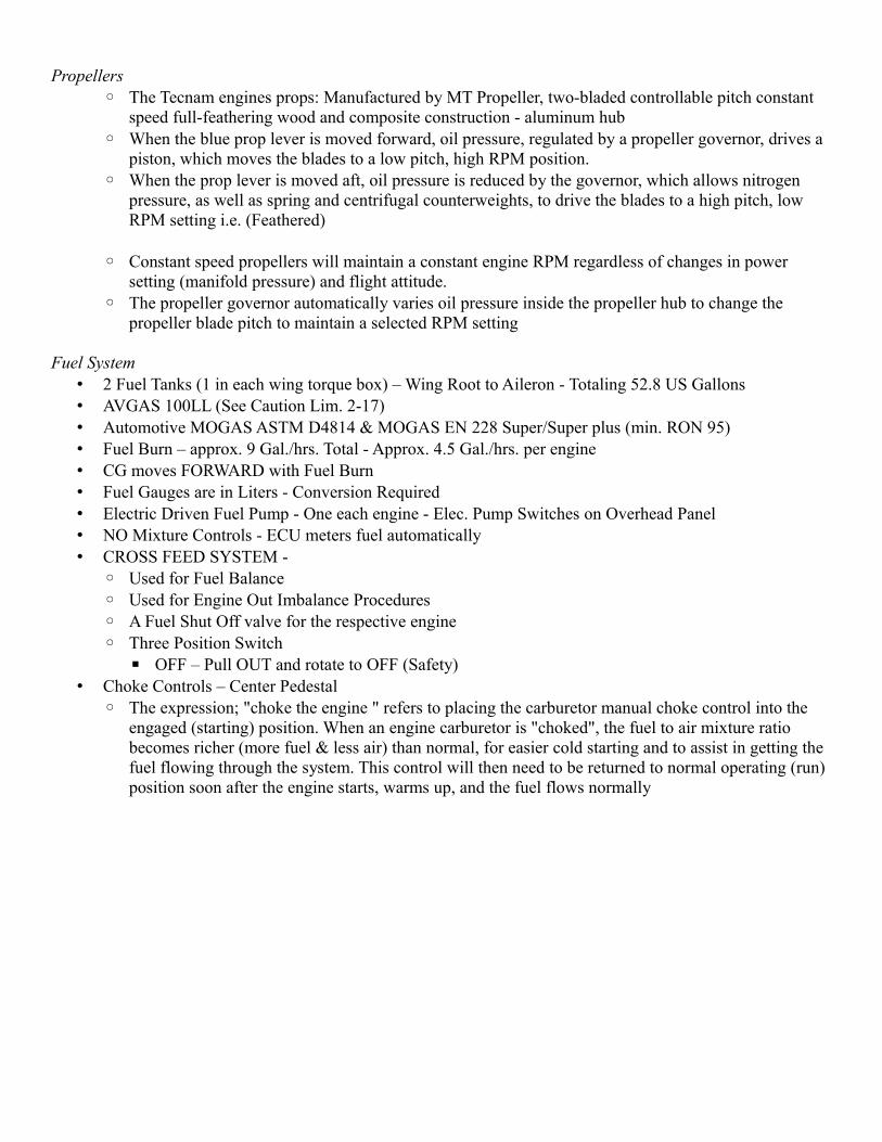
Propellers◦ The Tecnam engines props: Manufactured by MT Propeller, two-bladed controllable pitch constant
speed full-feathering wood and composite construction - aluminum hub◦ When the blue prop lever is moved forward, oil pressure, regulated by a propeller governor, drives a
piston, which moves the blades to a low pitch, high RPM position.◦ When the prop lever is moved aft, oil pressure is reduced by the governor, which allows nitrogen
pressure, as well as spring and centrifugal counterweights, to drive the blades to a high pitch, low RPM setting i.e. (Feathered)
◦ Constant speed propellers will maintain a constant engine RPM regardless of changes in power setting (manifold pressure) and flight attitude.
◦ The propeller governor automatically varies oil pressure inside the propeller hub to change the propeller blade pitch to maintain a selected RPM setting
Fuel System• 2 Fuel Tanks (1 in each wing torque box) – Wing Root to Aileron - Totaling 52.8 US Gallons• AVGAS 100LL (See Caution Lim. 2-17)• Automotive MOGAS ASTM D4814 & MOGAS EN 228 Super/Super plus (min. RON 95)• Fuel Burn – approx. 9 Gal./hrs. Total - Approx. 4.5 Gal./hrs. per engine• CG moves FORWARD with Fuel Burn• Fuel Gauges are in Liters - Conversion Required• Electric Driven Fuel Pump - One each engine - Elec. Pump Switches on Overhead Panel• NO Mixture Controls - ECU meters fuel automatically• CROSS FEED SYSTEM -
◦ Used for Fuel Balance ◦ Used for Engine Out Imbalance Procedures◦ A Fuel Shut Off valve for the respective engine◦ Three Position Switch
▪ OFF – Pull OUT and rotate to OFF (Safety)• Choke Controls – Center Pedestal
◦ The expression; "choke the engine " refers to placing the carburetor manual choke control into the engaged (starting) position. When an engine carburetor is "choked", the fuel to air mixture ratio becomes richer (more fuel & less air) than normal, for easier cold starting and to assist in getting the fuel flowing through the system. This control will then need to be returned to normal operating (run) position soon after the engine starts, warms up, and the fuel flows normally
Landing Gear• Electro-Hydraulic, Reversible Pump• Battery Bus Powered• Micro-Switches determine and report Gear Position• Gear Extension is also helped by GRAVITY• Two single tire Main Gear• One single tire Nose Gear
◦ Hydraulic pressure is supplied by an electrical/hydraulic pump• Gear Horn is activated
◦ On the ground if gear handle is in the up position – There is NO squat switch◦ In the air if power is idle or flaps in landing position with gear switch still in up position
• Push to Test Button to check that Gear Positon LIGHTS are operating - A BULBS TEST• Three GREEN Position Light Indicators for Gear Down and Locked • Red Gear In-Transit Light ANYTIME ANY Gear NOT Down and Locked Or in Transit• Maximum Nose Wheel Towing Angle of Turn is 20 degrees either side of center Do NOT exceed this
angle• Emergency Gear Extension should be done BOTH for Memory, and backed up BY CHECKLIST.
◦ Slow Aircraft below 122 KIAS◦ Landing Gear Control Lever – Down◦ Remove Emer. Gear Floor Cover◦ Right Control Lever – 90 deg. Counterclockwise - Allows Nose gear Deploy◦ Left Control Lever – 90 deg. Counterclockwise - Allows Main Landing Gear Deploy◦ Check for 3 Green Lights – Gear Down - Land as soon as possible
Brakes• Hydraulic Disc Brakes
◦ The reservoir is INDEPENDENT for the Landing Gear Hydraulic reservoir◦ Toe Brakes, at the top of the Rudder Brake peddles are used to activate brakes◦ Parking Brakes should NEVER be trusted during the Engine Run up and during the Before Takeoff
Checklist evolution◦ Brakes are Single Disc, Double Pucks - BOTH Main Gear◦ MASTER CYLINDERs are attached to BOTH Capt. and Co-Pilot’s Brakes◦ Capts. Brakes are plumbed thru the Co-Pilots Brakes then connected to the Parking Brake valve
Brake Pressure is then ported to the Brake Discs on each Main Gear◦ Parking Brake
▪ Setting the Parking Brake Valve BLOCK Hydraulic Pressure return from the Brakes, putting constant pressure to the Brake Pads. Toe Brake pressure is needed to set the Parking Brake
▪ Releasing the Parking Brake will open the valve, release the pressure, and releasing the Brake Pads
Flaps• Electronically Controlled - Continuous Mode
◦ Battery Bus Power◦ Single Electric Actuator moves Flap system Up – T/O – FULL
Stabilator• Push-Pull Rods connect Stabilator to the Duel Yoke System• Anti Tab Winglet” serves as Trim Tab Surface (electric and manual trim)• Autopilot pitch servo is connected to the Push-Pull Rod
Aileron• Conventional with Cables and Pulleys
Rudder• Operated through a Cable System• Rudder Trim is ELECTRICAL
Doors - There are 3 Doors• Main Door – Left Side• Emergency Door – Right Side• Ditching Emergency Door – TOP
These Doors (the Main Door and the Emergency Door) are SPECIAL based on the design of the Tecnam.When the respective Engines are started, Oil Pressure increase sends a signal to deactivate the door handles, This Signal CAN be OVERRIDEN by a Red Unlatch Solenoid Mechanism.
◦ Any voluntary operation of the manual by-pass solenoid lock causes the related Door Warning Light to illuminate
◦ Ditching Emergency Door is a Turn the Handle and Push out on the door operation▪ Yellow fluorescent handle can be opened from the OUTSIDE and fitted with a Safety Wire.
When it opens it stays connected via two cables to allow door to open FORWARD
Baggage Compartment• Baggage must be uniformly distributed on the floor• Weight cannot exceed 176lbs• Secure baggage prior to moving the aircraft
Ventilation• Ram Air vents via two outlet ports (left and right) provide front cabin ventilation• Two more outlets are located on the Cabin headliner in the passenger zone
Cabin Heat• Cabin Heat is produced by Engine Heat Exchangers
◦ Ram Air heated by Engine Exhaust, this is ducted to the cabin via heater ducts• Cabin Heat controls are located on the Lower side of the Left Instrument panel
◦ Left controls left heat exchanger◦ Right controls right heat exchanger
• Crew Heating outlets are located on the Cabin floor near the pedestal• Passenger zone outlets for heat are on the cabin overhead• Windshield defrost operation is via knob position on the pedestal
◦ Pull knob for hot air flow from the crew heating duct to the windshield