Embed Size (px)
Citation preview

PROLOGUE
You have purchased one of the most scientifically enhanced illuminated sights in the shooting industry. This illuminated sight is the result of years of research and study. This addresses the continued quest to match the technical advances of the industry to the necessities of the modern marksman. We offer our customers the best quality product at an affordable price. We are proud to present a new riflescope series with an exclusive tactical vision. In this scope, the craftsmanship of the past meets the technology of the twenty-first century, creating a unique concept.
A revolutionary system forms the structural base of this fine line of scopes:
2
TABLE OF CONTENTS
1. FEATURES 2. MOUNTING THE SIGHT3. MOUNTING THE LASER AND LIGHT (ONLY FOR “LL” MODELS)4. FOCUSING THE SIGHT5. ZEROING THE SIGHT6. RETICLES7. MAINTAING THE SIGHT
3
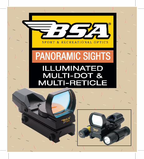
REFLEX LENS
LENS FRAME
SWITCH & INTENSITYCONTROL KNOB
3V LITHIUM BATTERY
RAIL
RUBBER DUST CAPALLEN WRENCH
BATTERY COVER
ELEVATION ADJUSTMENTSCREW
LED & MIRROR HOUSING
LOCKING SCREWFOR ELEVATIONADJUSTMENTS
RETICLE SELECTORKNOB (PMRS/ PMRGS)
DOT SELECTORKNOB (PMDS)
WINDAGE ADJUSTMENTSCREW (BACK)
FLASHLIGHT
LASER SIGHT
LASER LABEL
GENERAL INFO FOR PMDS / PMRS / PMRGS MODELS:
FOR PMRGSLL MODELS
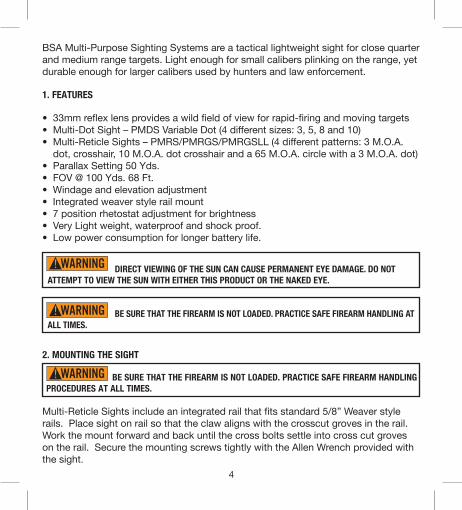
2. MOUNTING THE SIGHT
BE SURE THAT THE FIREARM IS NOT LOADED. PRACTICE SAFE FIREARM HANDLING PROCEDURES AT ALL TIMES.
Multi-Reticle Sights include an integrated rail that fits standard 5/8” Weaver style rails. Place sight on rail so that the claw aligns with the crosscut groves in the rail. Work the mount forward and back until the cross bolts settle into cross cut groves on the rail. Secure the mounting screws tightly with the Allen Wrench provided with the sight.
4
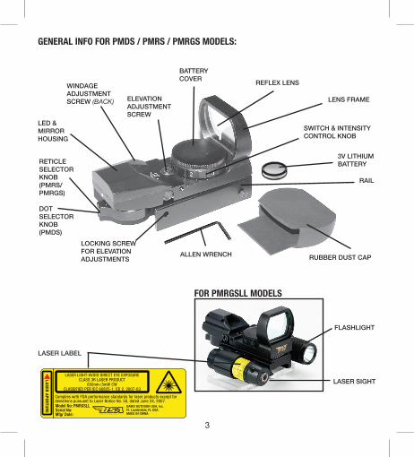
BSA Multi-Purpose Sighting Systems are a tactical lightweight sight for close quarter and medium range targets. Light enough for small calibers plinking on the range, yet durable enough for larger calibers used by hunters and law enforcement.
1. FEATURES
• 33mm reflex lens provides a wild field of view for rapid-firing and moving targets• Multi-Dot Sight – PMDS Variable Dot (4 different sizes: 3, 5, 8 and 10)• Multi-Reticle Sights – PMRS/PMRGS/PMRGSLL (4 different patterns: 3 M.O.A.
dot, crosshair, 10 M.O.A. dot crosshair and a 65 M.O.A. circle with a 3 M.O.A. dot)• Parallax Setting 50 Yds.• FOV @ 100 Yds. 68 Ft.• Windage and elevation adjustment• Integrated weaver style rail mount• 7 position rhetostat adjustment for brightness• Very Light weight, waterproof and shock proof.• Low power consumption for longer battery life.
DIRECT VIEWING OF THE SUN CAN CAUSE PERMANENT EYE DAMAGE. DO NOT ATTEMPT TO VIEW THE SUN WITH EITHER THIS PRODUCT OR THE NAKED EYE.
BE SURE THAT THE FIREARM IS NOT LOADED. PRACTICE SAFE FIREARM HANDLING AT ALL TIMES.
DANGER!
WARNING!
CAUTION!DANGER!
WARNING!
CAUTION!
DANGER!
WARNING!
CAUTION!
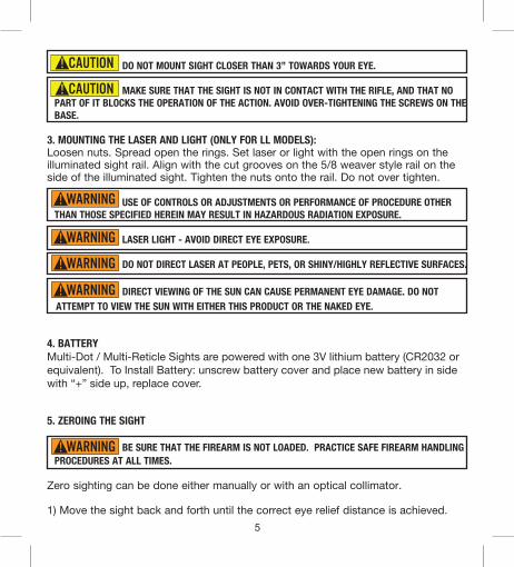
DO NOT MOUNT SIGHT CLOSER THAN 3” TOWARDS YOUR EYE.
MAKE SURE THAT THE SIGHT IS NOT IN CONTACT WITH THE RIFLE, AND THAT NO PART OF IT BLOCKS THE OPERATION OF THE ACTION. AVOID OVER-TIGHTENING THE SCREWS ON THE BASE.
3. MOUNTING THE LASER AND LIGHT (ONLY FOR LL MODELS):Loosen nuts. Spread open the rings. Set laser or light with the open rings on the illuminated sight rail. Align with the cut grooves on the 5/8 weaver style rail on the side of the illuminated sight. Tighten the nuts onto the rail. Do not over tighten.
USE OF CONTROLS OR ADJUSTMENTS OR PERFORMANCE OF PROCEDURE OTHER THAN THOSE SPECIFIED HEREIN MAY RESULT IN HAZARDOUS RADIATION EXPOSURE.
LASER LIGHT - AVOID DIRECT EYE EXPOSURE.
DO NOT DIRECT LASER AT PEOPLE, PETS, OR SHINY/HIGHLY REFLECTIVE SURFACES.
DIRECT VIEWING OF THE SUN CAN CAUSE PERMANENT EYE DAMAGE. DO NOT ATTEMPT TO VIEW THE SUN WITH EITHER THIS PRODUCT OR THE NAKED EYE.
4. BATTERYMulti-Dot / Multi-Reticle Sights are powered with one 3V lithium battery (CR2032 or equivalent). To Install Battery: unscrew battery cover and place new battery in side with “+” side up, replace cover.
5. ZEROING THE SIGHT
BE SURE THAT THE FIREARM IS NOT LOADED. PRACTICE SAFE FIREARM HANDLING PROCEDURES AT ALL TIMES.
Zero sighting can be done either manually or with an optical collimator.
1) Move the sight back and forth until the correct eye relief distance is achieved.
5
DANGER!
WARNING!
CAUTION!DANGER!
WARNING!
CAUTION!
DANGER!
WARNING!
CAUTION!DANGER!
WARNING!
CAUTION!
DANGER!
WARNING!
CAUTION!
DANGER!
WARNING!
CAUTION!
DANGER!
WARNING!
CAUTION!

2) Tighten the crossbolt nuts.
3) Select the dot style (PMDS) or the reticle style (PMRS/PMRGS/PMRGSLL) by rotating the selector knob. Set brightness by using the switch & intensity control knob. With the sight mounted, rest the gun on a solid support and aim at a target 50 to 100 yards away. Test shots should be done in the same conditions to achieve maximum accuracy for adjustment. The use of a firm rest and same ammunition is recommended. Each click adjustment moves the point of impact 1 MOA (approximately1” @ 100 yards, 1/2” @ 50 yards).
a. Locate the “Locking Screw for Elevation” and loosen screw by rotating 2 turns counter clockwise. Make rough adjustment to elevation at this time (DO NOT discharge gun while locking screw is loose).
b. Tighten locking screwc. Make rough windage adjustmentd. It is recommended to use grouping of three shots to zero in sight.e. After adjusting for windage, gently loosen “Locking Screw for Elevation” and
fine tune the elevation.f. Tighten “Locking Screw for Elevation” for next group of shots.g. Repeat steps 4 to 6 until sight is zeroed.
3) Attach the collimator.
Attaching boresighter collimator to firearms other than shotguns:Select the appropriate bore stud from the kit and insert the notched end into the collimator stud housing. Hand-tighten the silver locking screw to secure the stud. Insert the other end of the stud into the muzzle.
Attaching boresighter to shotguns:Insert the notched end with the adjusting screw/knob into the collimator.Hand-tighten the locking screw. Insert the other end of the stud into the muzzle. Turn the adjusting screw/knob counterclockwise until the desired gauge or bore diameter is achieved and the collimator is secured.The adjustable collimator covers a wide range of different gauges and black powder caliber.
6
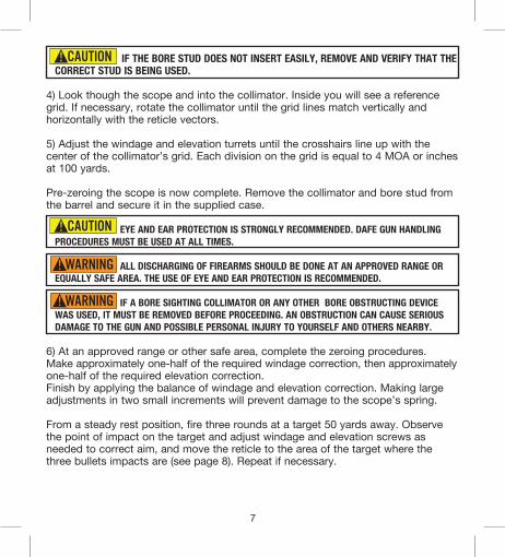
IF THE BORE STUD DOES NOT INSERT EASILY, REMOVE AND VERIFY THAT THE CORRECT STUD IS BEING USED.
4) Look though the scope and into the collimator. Inside you will see a reference grid. If necessary, rotate the collimator until the grid lines match vertically and horizontally with the reticle vectors.
5) Adjust the windage and elevation turrets until the crosshairs line up with the center of the collimator’s grid. Each division on the grid is equal to 4 MOA or inches at 100 yards.
Pre-zeroing the scope is now complete. Remove the collimator and bore stud from the barrel and secure it in the supplied case.
EYE AND EAR PROTECTION IS STRONGLY RECOMMENDED. DAFE GUN HANDLING PROCEDURES MUST BE USED AT ALL TIMES.
ALL DISCHARGING OF FIREARMS SHOULD BE DONE AT AN APPROVED RANGE OR EQUALLY SAFE AREA. THE USE OF EYE AND EAR PROTECTION IS RECOMMENDED.
IF A BORE SIGHTING COLLIMATOR OR ANY OTHER BORE OBSTRUCTING DEVICE WAS USED, IT MUST BE REMOVED BEFORE PROCEEDING. AN OBSTRUCTION CAN CAUSE SERIOUS DAMAGE TO THE GUN AND POSSIBLE PERSONAL INJURY TO YOURSELF AND OTHERS NEARBY.
6) At an approved range or other safe area, complete the zeroing procedures. Make approximately one-half of the required windage correction, then approximately one-half of the required elevation correction.Finish by applying the balance of windage and elevation correction. Making large adjustments in two small increments will prevent damage to the scope’s spring.
From a steady rest position, fire three rounds at a target 50 yards away. Observe the point of impact on the target and adjust windage and elevation screws as needed to correct aim, and move the reticle to the area of the target where the three bullets impacts are (see page 8). Repeat if necessary.
7
DANGER!
WARNING!
CAUTION!
DANGER!
WARNING!
CAUTION!
DANGER!
WARNING!
CAUTION! DANGER!
WARNING!
CAUTION!
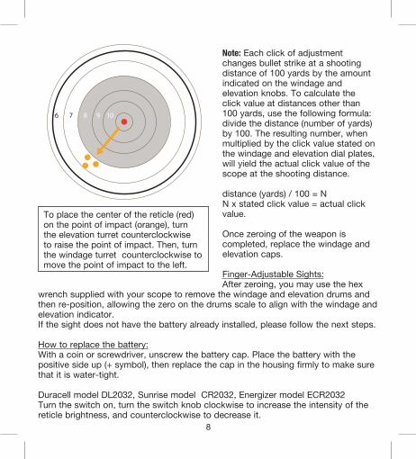
Note: Each click of adjustment changes bullet strike at a shooting distance of 100 yards by the amount indicated on the windage and elevation knobs. To calculate the click value at distances other than 100 yards, use the following formula: divide the distance (number of yards) by 100. The resulting number, when multiplied by the click value stated on the windage and elevation dial plates, will yield the actual click value of the scope at the shooting distance.
distance (yards) / 100 = NN x stated click value = actual click value.
Once zeroing of the weapon is completed, replace the windage and elevation caps.
Finger-Adjustable Sights:After zeroing, you may use the hex
wrench supplied with your scope to remove the windage and elevation drums and then re-position, allowing the zero on the drums scale to align with the windage and elevation indicator.If the sight does not have the battery already installed, please follow the next steps.
How to replace the battery:With a coin or screwdriver, unscrew the battery cap. Place the battery with the positive side up (+ symbol), then replace the cap in the housing firmly to make sure that it is water-tight.
Duracell model DL2032, Sunrise model CR2032, Energizer model ECR2032Turn the switch on, turn the switch knob clockwise to increase the intensity of the reticle brightness, and counterclockwise to decrease it.
8
To place the center of the reticle (red) on the point of impact (orange), turn the elevation turret counterclockwise to raise the point of impact. Then, turn the windage turret counterclockwise to move the point of impact to the left.
Zeroing the sight manually:
If you have a bolt action rifle: Open the action of the firearm and remove the bolt. Looking through the bore of the rifle, make sure that the center of the target is in the center of your view.To pre-zero the sight, adjust the windage and elevation screws so that the image appearing at the center of your bore is the same centered in the riflescope reticle.If the firearm you own is not a bolt action, we recommend the use of an optical collimator.
Zeroing the sight with a Collimator or Boresighter:
BE CERTAIN THAT THE GUN IS NOT LOADED, THE ACTION IS OPEN, AND THE MUZZLE IS POINTED IN A SAFE DIRECTION. SAFE GUN HANDLING PROCEDURES MUST BE USED AT ALL TIMES.
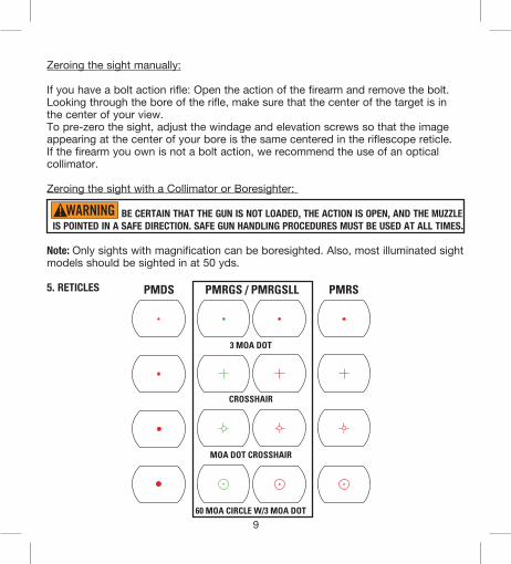
Note: Only sights with magnification can be boresighted. Also, most illuminated sight models should be sighted in at 50 yds.
5. RETICLES
9
DANGER!
WARNING!
CAUTION!
PMRGS / PMRGSLL
3 MOA DOT
CROSSHAIR
MOA DOT CROSSHAIR
60 MOA CIRCLE W/3 MOA DOT
PMDS PMRS
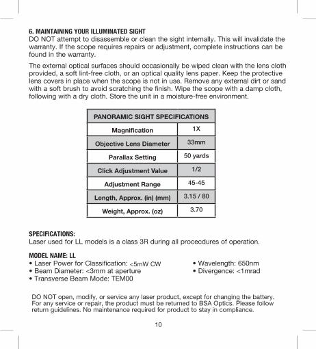
6. MAINTAINING YOUR ILLUMINATED SIGHTDO NOT attempt to disassemble or clean the sight internally. This will invalidate the warranty. If the scope requires repairs or adjustment, complete instructions can be found in the warranty. The external optical surfaces should occasionally be wiped clean with the lens cloth provided, a soft lint-free cloth, or an optical quality lens paper. Keep the protective lens covers in place when the scope is not in use. Remove any external dirt or sand with a soft brush to avoid scratching the finish. Wipe the scope with a damp cloth, following with a dry cloth. Store the unit in a moisture-free environment.
10
DO NOT open, modify, or service any laser product, except for changing the battery. For any service or repair, the product must be returned to BSA Optics. Please follow return guidelines. No maintenance required for product to stay in compliance.
PANORAMIC SIGHT SPECIFICATIONS
Magnification 1X
Objective Lens Diameter 33mm
Parallax Setting 50 yards
Click Adjustment Value 1/2
Adjustment Range 45-45
Length, Approx. (in) (mm) 3.15 / 80
Weight, Approx. (oz) 3.70
SPECIFICATIONS:Laser used for LL models is a class 3R during all procecdures of operation.
MODEL NAME: LL• Laser Power for Classification: <5mW CW • Wavelength: 650nm• Beam Diameter: <3mm at aperture • Divergence: <1mrad• Transverse Beam Mode: TEM00

11
TROUBLE SHOOTING TIPS
Inaccuracy Issues1) First check your mount. Using your bare hands only, softly twist the sight in the
rings, check for any movement. If there is any movement, re-tighten the mount. Non-permanent thread lock tight is recommended.
2) Use a bench rest or sandbag to support the forearm and butt stock when making windage and elevation adjustments. This will help eliminate movement.
3) Always follow through with every shot.4) Always use the ammunition of the same bullet type and weight.5) Check that your rifle is properly bedded in the stock. A loose stock can create
changes to the point of impact.6) Check that your barrel and chamber are clean. Damaged rifling or excessive
grease can cause inaccuracy.7) Always make adjustments in small increments.
For questions on our products and for complete instructions on warranty and repair, contact GAMO OUTDOOR USA customer service at (954) 581-2144 or visit www.bsaoptics.com
FOR RETURNING PRODUCTS
Return products following the warranty guidelines.A brief description is included below.1. Remove any accessories and rings2. Include a note with a brief description of the problem, address, telephone
number, and email address3. A $10 check for return shipping and processing fees and proof of purchase.4. We recommend using a shipping method with a tracking number (Fedex,UPS
ect.). BSA optics cannot be held liable for lost or damaged items.*Please note if your product is not registered you must have proof of original
purchase, or you will be subject to repair fees. (see warranty)
Ship Products To:GAMO OUTDOOR USA, Inc.1475 S. Sam Houston Blvd.Houston, MO 65483
© 2010 GAMO OUTDOOR USA, Inc.Ft. Lauderdale, FL 33314 USA
Printed in China • BD042010 • Multi-Dot_Sight_Manual.indd