Embed Size (px)
Citation preview
Multi Converter-Unified Power Quality Conditioner using
Generalized Fryze Control Strategy
1
B.RAJANI, 2K.SATYANARAYANA, 3SABBELLA.V.V.S K.REDDY,4
M.MANI SHANKAR
1(Associate prof, Dept of EEE, Pragati Engineering college, Surampalem ,E.g.dt,AP,533437) 2(Professor& HOD, Dept of EEE, Pragati Engineering college, Surampalem ,E.g.dt,AP,53337) 3(Assistant Professor,Dept of EEE , Pragati Engineering college, Surampalem ,E.g.dt,AP,53337) 4(Assistant Professor, Dept of EEE, Pragati Engineering college, Surampalem ,E.g.dt,AP,53337)
Abstract This paper presents a fryze control strategy for a Multi converter unified power quality
conditioner. This control strategy is used in three-phase three-wire systems The MCUPQC
device is a combination of two series-active filters with one shunt-active filter .The active power
filter controller is based on the instantaneous power theory. And it can be classified in two
groups. The first one is based on the transformation from abc phase to three-orthogonal axes,
and other is based on directly from abc. In first method abc phases are converted into αβ0
transformation and is called as p-q theory In second method it deals with directly abc phase, so
it is called as abc theory. In second theory current minimization method is used to apply in real
time application. The second method is proposed as control strategy in this paper because it has
some advantages over p-q theory. The shunt active power filter is used for current compensation
and series active power filter is used for voltage compensation. The MATLAB\SIMULINK
software with P-Q and fryze control strategy is compared in this paper.
Index Terms— Active filters, Generalized fryze theory, power quality, Instantaneous active and reactive power
1. INTRODUCTION
The present power distribution system is usually configured as a three-phase
three-wire or four-wire structure featuring a power-limit voltage source with significant source
impedance, and an aggregation of various types of loads. Ideally, the system should provide a
balanced and pure sinusoidal three-phase voltage of constant amplitude to the loads; and the
loads should draw a current from the line with unity power factor, zero harmonics, and balanced
phases.
In Four-wire systems, no excessive neutral current should exist. As a result, the
maximum power capacity and efficiency of the energy delivery are achieved, minimum
perturbation to other appliances is ensured, and safe operation is warranted. However, with a fast
increasing number of applications of industry electronics connected to the distribution systems
today, including nonlinear, switching, reactive, single-phase and unbalanced three-phase loads, a
complex problem of power quality evolved characterized by the voltage and current harmonics,
unbalances, low Power Factor (PF). In recent years active methods for power quality control
have become more attractive compared with passive ones due to their fast response, smaller size,
Pramana Research Journal
Volume 9, Issue 4, 2019
ISSN NO: 2249-2976
https://pramanaresearch.org/584
and higher performance. For example, Static VAR Compensator (SVC) have been reported to
improve the power factor; Power Factor Corrector (PFC) and Active Power Filters (APF) have
the ability of current harmonics suppression and power factor correction; some active circuits
were developed to compensate unbalanced currents as well as limit the neutral current.
In general, parallel-connected converters have the ability to improve the current quality
while the series-connected regulators inserted between the load and the supply, improve the
voltage quality. The active filter which have ability to compensate nonlinear load current and
unbalance supply voltage and they are used as shunt active filter and series active filter
respectively. If we use two or more series active filters and one shunt active filter then it is called
as Multi Converter Unified Power Quality Conditioner (MC-UPQC), which has ability to solved
problem related to current and voltage harmonics simultaneously.
2. MC-UPQC System Circuit Configuration
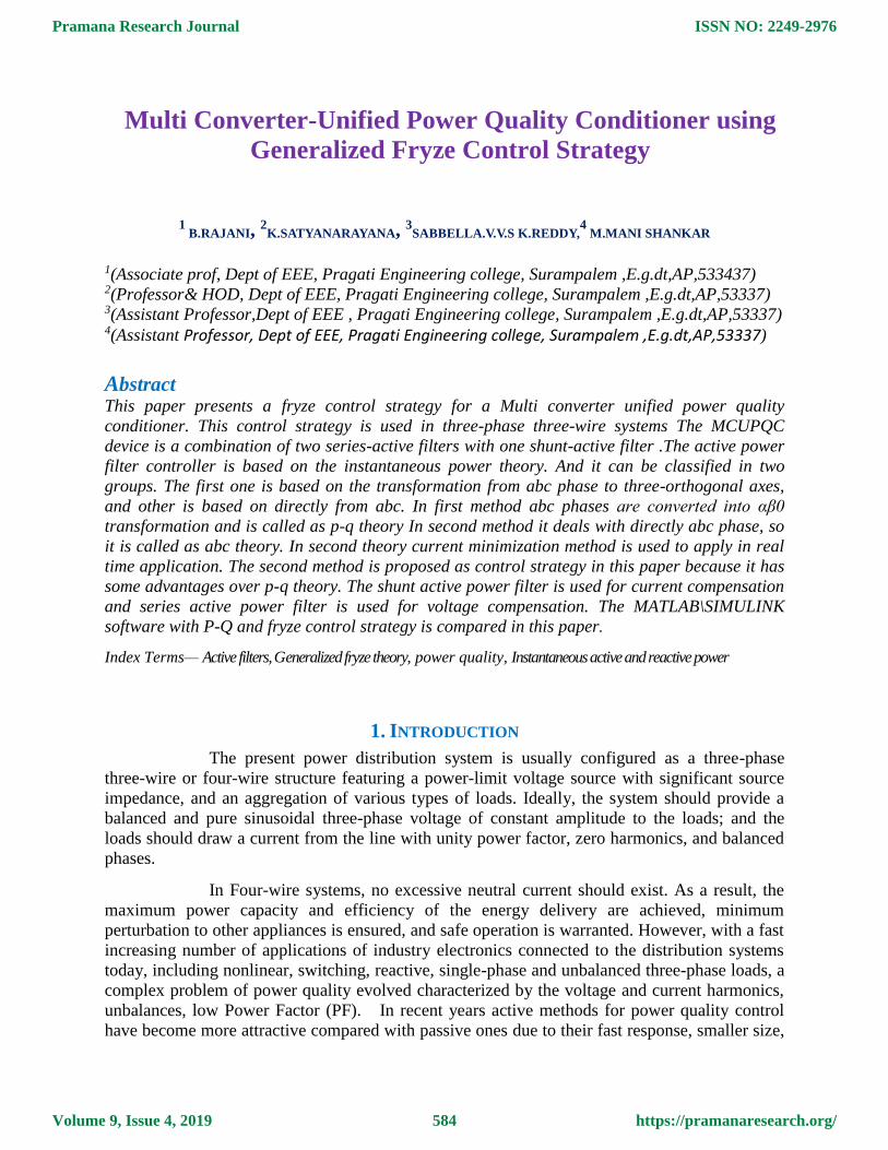
The single-line diagram of a distribution system with an MC-UPQC is shown in
Fig. 5.1. As shown in this figure, two feeders connected to two different substations supply the
loads L1 and L2. The MC-UPQC is connected to two buses BUS1 and BUS2 with voltages of
ut1 and ut2 respectively. The shunt part of the MC-UPQC is also connected to load L1 with a
current of it1. Supply voltages are denoted by us1 andus2 while load voltages are uL1 and uL2.
Finally, feeder currents are denoted by is1 and is2 load currentsareit1 and it2. Bus voltages ut1 and
ut2 are distorted and may be subjected to sag/swell. The load L1 is a nonlinear/sensitive load
which needs a pure sinusoidal voltage for proper operation while its current is non sinusoidal
and contains harmonics. The load L2 is a sensitive/critical load which needs a purely sinusoidal
voltage and must be fully protected against distortion, sag/swell, and interruption.These types of
loads primarily include production industries and critical service providers, such as medical
centers, airports, or broadcasting centers where voltage interruption can result in severe
economical losses or human damages.
Fig.1.Single Line Diagram of MC-UPQC
2.1 MC–UPQC Structure
The internal structure of the MC–UPQC is shown in Fig.5.2. It consists of three
VSCs (VSC1,VSC2, and VSC3) which are connected back to back through a common dc-link
capacitor. In the proposed configuration, VSC1 is connected in series with BUS1 and VSC2 is
connected in parallel with load L1 at the end of Feeder1. VSC3 is connected in series with
BUS2 at the Feeder2.
Pramana Research Journal
Volume 9, Issue 4, 2019
ISSN NO: 2249-2976
https://pramanaresearch.org/585
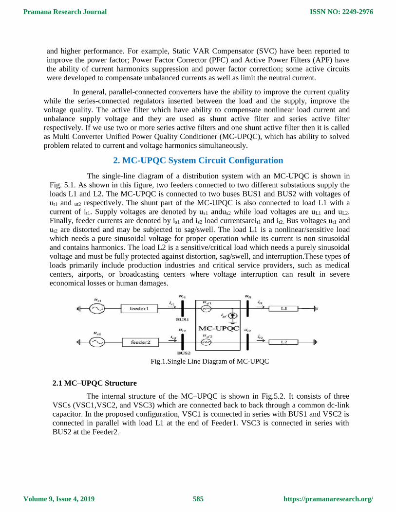
2.2 Typical MC-UPQC used in a distribution system
As shown in Fig.2, all converters are supplied from a common dc-link capacitor and
connected to the distribution system through a transformer. Secondary (distribution) sides
of the series-connected transformers are directly connected in series with BUS1 and BUS2, and
the secondary (distribution) side of the shunt-connected transformer is connected in parallel
with load L1.
The aims of the MC-UPQC shown in Fig.2 are: 1. To regulate the load voltage against sag/swell and disturbances in the system to protect the
nonlinear/sensitive load L1;
2. To regulate the load voltage against sag/swell, interruption, and disturbances in the system to
protect the sensitive/ critical load L2;
3. To compensate for the reactive and harmonic components of nonlinear load current.
4. In order to achieve these goals, series VSCs (i.e., VSC1 and VSC3) operate as voltage controllers
while the shunt VSC (i.e., VSC2) operates as a current controller.
Fig.2.Typical MC-UPQC Used In Distribution System
2.3 Control Strategy
As shown in Fig.2, the MC-UPQC consists of two series VSCs and one shunt VSC which
are controlled independently. The switching control strategy for series VSCs and shunt VSC are
Generalized Fryze Control Strategy.
3. Generalized Fryze Current Compensation
Fig.3 shows the generalized fryze current control strategy for shunt active filter.
This block diagram is used to calculate the compensating current. The first block is used to
calculate the instantaneous fryze conductance by the use of load current and load voltage. This
conductance is passed through the low pass filter and average value will be calculated, which is
used to calculate the active current. In that calculation load voltage is also used. Now at last
Pramana Research Journal
Volume 9, Issue 4, 2019
ISSN NO: 2249-2976
https://pramanaresearch.org/586
these active currents will be subtracted from the load current to calculate the compensating
current.
Fig.3. Generalized Fryze Current Compensation
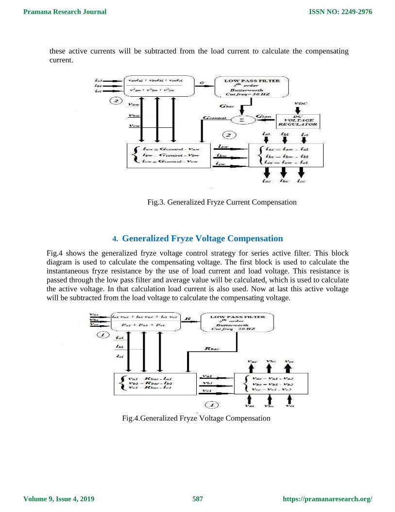
4. Generalized Fryze Voltage Compensation
Fig.4 shows the generalized fryze voltage control strategy for series active filter. This block
diagram is used to calculate the compensating voltage. The first block is used to calculate the
instantaneous fryze resistance by the use of load current and load voltage. This resistance is
passed through the low pass filter and average value will be calculated, which is used to calculate
the active voltage. In that calculation load current is also used. Now at last this active voltage
will be subtracted from the load voltage to calculate the compensating voltage.
Fig.4.Generalized Fryze Voltage Compensation
Pramana Research Journal
Volume 9, Issue 4, 2019
ISSN NO: 2249-2976
https://pramanaresearch.org/587
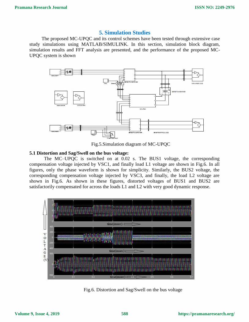
5. Simulation Studies The proposed MC-UPQC and its control schemes have been tested through extensive case
study simulations using MATLAB/SIMULINK. In this section, simulation block diagram,
simulation results and FFT analysis are presented, and the performance of the proposed MC-
UPQC system is shown
Fig.5.Simulation diagram of MC-UPQC
5.1 Distortion and Sag/Swell on the bus voltage:
The MC–UPQC is switched on at 0.02 s. The BUS1 voltage, the corresponding
compensation voltage injected by VSC1, and finally load L1 voltage are shown in Fig.6. In all
figures, only the phase waveform is shown for simplicity. Similarly, the BUS2 voltage, the
corresponding compensation voltage injected by VSC3, and finally, the load L2 voltage are
shown in Fig.6. As shown in these figures, distorted voltages of BUS1 and BUS2 are
satisfactorily compensated for across the loads L1 and L2 with very good dynamic response.
Fig.6. Distortion and Sag/Swell on the bus voltage
Pramana Research Journal
Volume 9, Issue 4, 2019
ISSN NO: 2249-2976
https://pramanaresearch.org/588
The nonlinear load current, its corresponding compensation current injected by VSC2,
compensated Feeder1 current, and, finally, the dc-link capacitor voltage are shown in Fig. 10.
The distorted nonlinear load current is compensated very well, and the total harmonic distortion
(THD) of the feeder current is reduced from 28.5% to less than 5%. Also, the dc voltage
regulation loop has functioned properly under all disturbances, such as sag/swell in both feeders
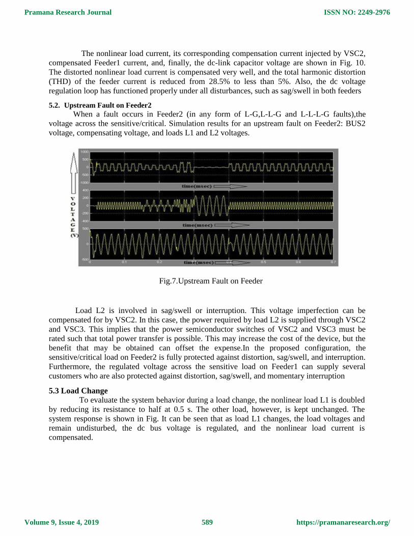
5.2. Upstream Fault on Feeder2
When a fault occurs in Feeder2 (in any form of L-G,L-L-G and L-L-L-G faults),the
voltage across the sensitive/critical. Simulation results for an upstream fault on Feeder2: BUS2
voltage, compensating voltage, and loads L1 and L2 voltages.
Fig.7.Upstream Fault on Feeder
Load L2 is involved in sag/swell or interruption. This voltage imperfection can be
compensated for by VSC2. In this case, the power required by load L2 is supplied through VSC2
and VSC3. This implies that the power semiconductor switches of VSC2 and VSC3 must be
rated such that total power transfer is possible. This may increase the cost of the device, but the
benefit that may be obtained can offset the expense.In the proposed configuration, the
sensitive/critical load on Feeder2 is fully protected against distortion, sag/swell, and interruption.
Furthermore, the regulated voltage across the sensitive load on Feeder1 can supply several
customers who are also protected against distortion, sag/swell, and momentary interruption
5.3 Load Change
To evaluate the system behavior during a load change, the nonlinear load L1 is doubled
by reducing its resistance to half at 0.5 s. The other load, however, is kept unchanged. The
system response is shown in Fig. It can be seen that as load L1 changes, the load voltages and
remain undisturbed, the dc bus voltage is regulated, and the nonlinear load current is
compensated.
Pramana Research Journal
Volume 9, Issue 4, 2019
ISSN NO: 2249-2976
https://pramanaresearch.org/589
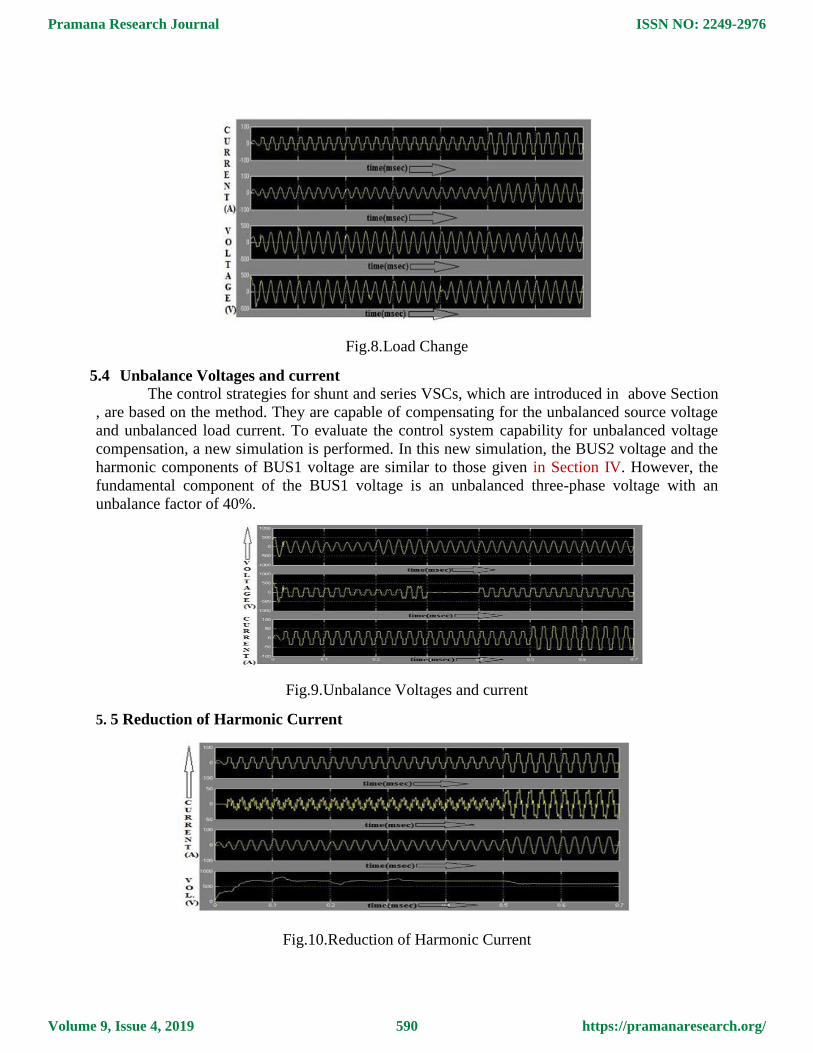
Fig.8.Load Change
5.4 Unbalance Voltages and current
The control strategies for shunt and series VSCs, which are introduced in above Section
, are based on the method. They are capable of compensating for the unbalanced source voltage
and unbalanced load current. To evaluate the control system capability for unbalanced voltage
compensation, a new simulation is performed. In this new simulation, the BUS2 voltage and the
harmonic components of BUS1 voltage are similar to those given in Section IV. However, the
fundamental component of the BUS1 voltage is an unbalanced three-phase voltage with an
unbalance factor of 40%.
Fig.9.Unbalance Voltages and current
5. 5 Reduction of Harmonic Current
Fig.10.Reduction of Harmonic Current
Pramana Research Journal
Volume 9, Issue 4, 2019
ISSN NO: 2249-2976
https://pramanaresearch.org/590
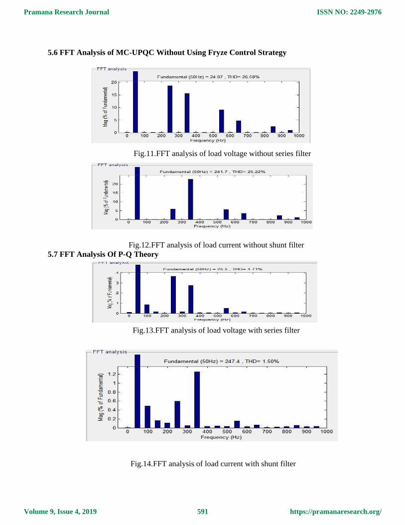
5.6 FFT Analysis of MC-UPQC Without Using Fryze Control Strategy
Fig.11.FFT analysis of load voltage without series filter
Fig.12.FFT analysis of load current without shunt filter
5.7 FFT Analysis Of P-Q Theory
Fig.13.FFT analysis of load voltage with series filter
Fig.14.FFT analysis of load current with shunt filter
Pramana Research Journal
Volume 9, Issue 4, 2019
ISSN NO: 2249-2976
https://pramanaresearch.org/591
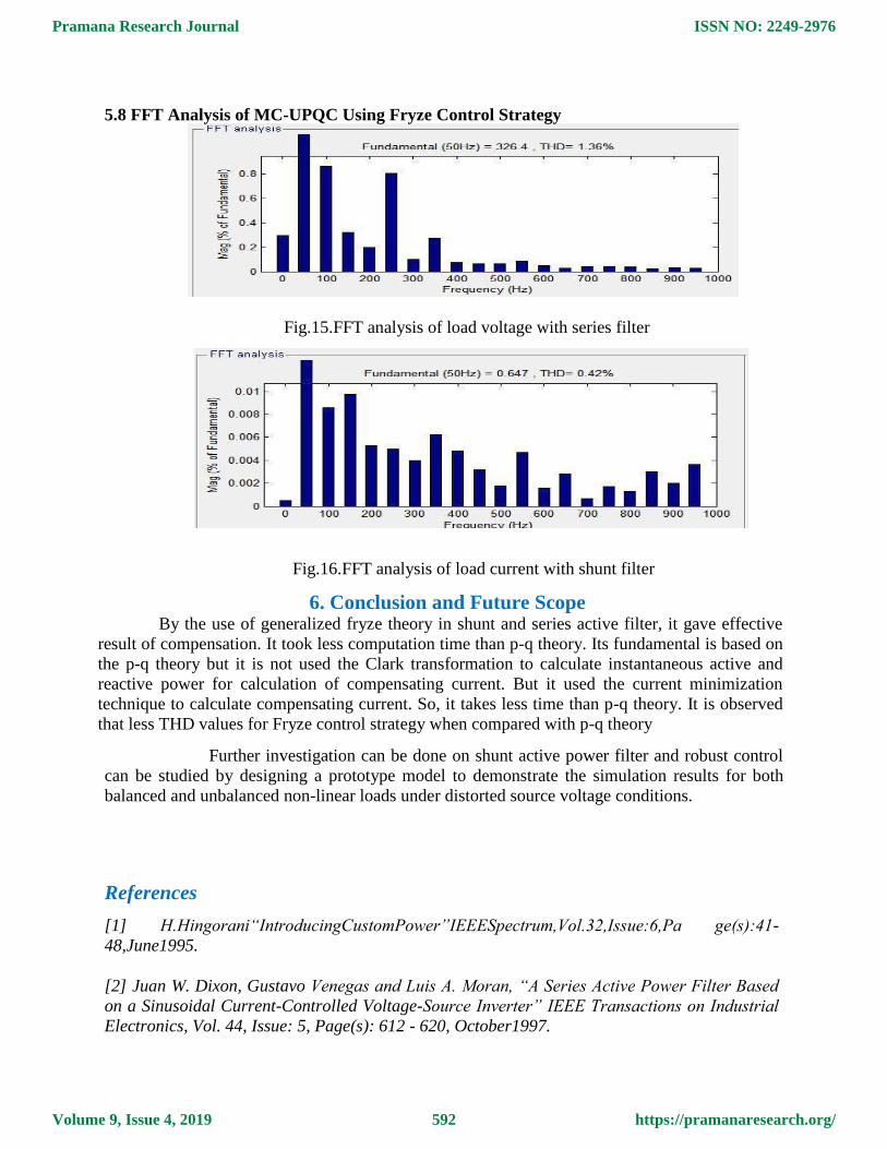
5.8 FFT Analysis of MC-UPQC Using Fryze Control Strategy
Fig.15.FFT analysis of load voltage with series filter
Fig.16.FFT analysis of load current with shunt filter
6. Conclusion and Future Scope By the use of generalized fryze theory in shunt and series active filter, it gave effective
result of compensation. It took less computation time than p-q theory. Its fundamental is based on
the p-q theory but it is not used the Clark transformation to calculate instantaneous active and
reactive power for calculation of compensating current. But it used the current minimization
technique to calculate compensating current. So, it takes less time than p-q theory. It is observed
that less THD values for Fryze control strategy when compared with p-q theory
Further investigation can be done on shunt active power filter and robust control
can be studied by designing a prototype model to demonstrate the simulation results for both
balanced and unbalanced non-linear loads under distorted source voltage conditions.
References
[1] H.Hingorani“IntroducingCustomPower”IEEESpectrum,Vol.32,Issue:6,Pa ge(s):41-
48,June1995.
[2] Juan W. Dixon, Gustavo Venegas and Luis A. Moran, “A Series Active Power Filter Based
on a Sinusoidal Current-Controlled Voltage-Source Inverter” IEEE Transactions on Industrial
Electronics, Vol. 44, Issue: 5, Page(s): 612 - 620, October1997.
Pramana Research Journal
Volume 9, Issue 4, 2019
ISSN NO: 2249-2976
https://pramanaresearch.org/592
[3] J. Barros, M.de Apraiz, and R. I. Diego, “Measurement of Sub harmonicsIn Power
Voltages”, Power Tech, IEEE Lausanne, Page(s): 1736 – 1740,2007.
[4] Yash Pal, A. Swarup and Bhim Singh,“A Review of Compensating Type Custom Power
Devices for Power Quality Improvement” 2008 Joint International Conference on Power
System Technology (POWERCON) and IEEE Power India Conference New Delhi, India.
[5] Mojtaba Nemati, Hesam Addin You sefian and Rouhollah Afshari,“Recognize the Role of
DVR in Power Systems”, International Journal of Recent Trends in
EngineeringVol.2,Page(s):13-15,November2009.
[6] Mahesh Singh and VaibhavTiwari, “Modeling analysis and solution of Power Quality
Problems”, http://eeeic.org/proc/papers/50.pdf.
[7] ChellaliBenachaiba and BrahimFerdi, “Voltage Quality Improvement Using DVR”,
Electrical Power Quality and Utilization, Journal Vol. XIV, No. 1,2008.
[8] HirofumiAkagi, EdsonHirokazu and Mauricio Aredes ,instantaneous power theory and
applications to power conditioning, a john wiley & sons, inc., publication, 2007, pp.41-371.
[9] Emílio F. Couto, Júlio S. Martins, João L. Afonso, “Simulation Results of a Shunt Active
Power Filter with Control Based on p-q Theory”, Department of Industrial
Electronic University of Minho.
[10] Bahr Eldin. S. M, K. S. Rama Rao, Rosdiazli Ibrahim and N. Perumal, “Cascade
[11] Roger C. Dugan“ Electrical Power Systems Quality” Text Book Pg.No199-285.
[12] https//MC-UPQC.net/archeive/V2/13/IJRET20140304104.PDF
Pramana Research Journal
Volume 9, Issue 4, 2019
ISSN NO: 2249-2976
https://pramanaresearch.org/593