Embed Size (px)
Citation preview
MULTI-COMPONENT FUEL VAPORIZATION AND FLASH BOILING
Chia-Fon LeeDepartment of Mechanical Science and Engineering
University of Illinois at Urbana-Champaign
June 7, 2017DOE EERE Vehicle Technologies Office
Annual Merit Review Meeting
This presentation does not contain any proprietary, confidential, or otherwise restricted information
Project ID # ACS106
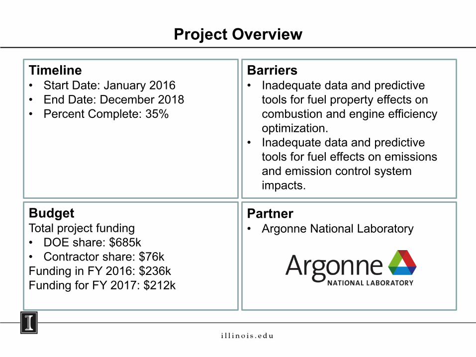
Barriers• Inadequate data and predictive
tools for fuel property effects on combustion and engine efficiency optimization.
• Inadequate data and predictive tools for fuel effects on emissions and emission control system impacts.
BudgetTotal project funding• DOE share: $685k • Contractor share: $76k Funding in FY 2016: $236k Funding for FY 2017: $212k
Partner• Argonne National Laboratory
Project Overview
Timeline• Start Date: January 2016• End Date: December 2018• Percent Complete: 35%
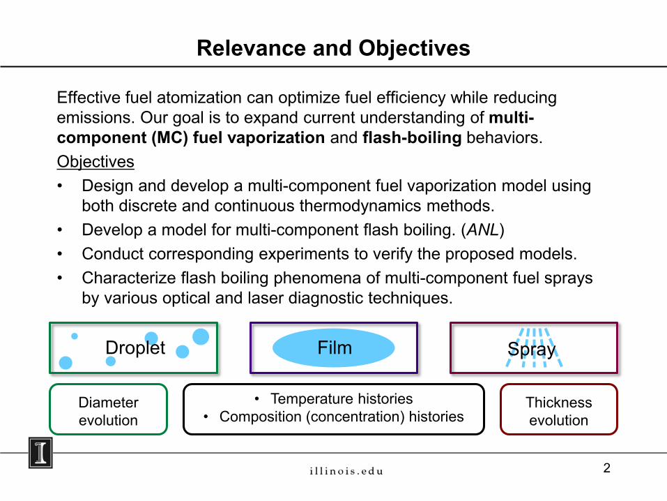
Effective fuel atomization can optimize fuel efficiency while reducing emissions. Our goal is to expand current understanding of multi-component (MC) fuel vaporization and flash-boiling behaviors. Objectives• Design and develop a multi-component fuel vaporization model using
both discrete and continuous thermodynamics methods. • Develop a model for multi-component flash boiling. (ANL)• Conduct corresponding experiments to verify the proposed models.• Characterize flash boiling phenomena of multi-component fuel sprays
by various optical and laser diagnostic techniques.
Relevance and Objectives
Droplet Film Spray
• Temperature histories• Composition (concentration) histories
Diameterevolution
Thicknessevolution
2
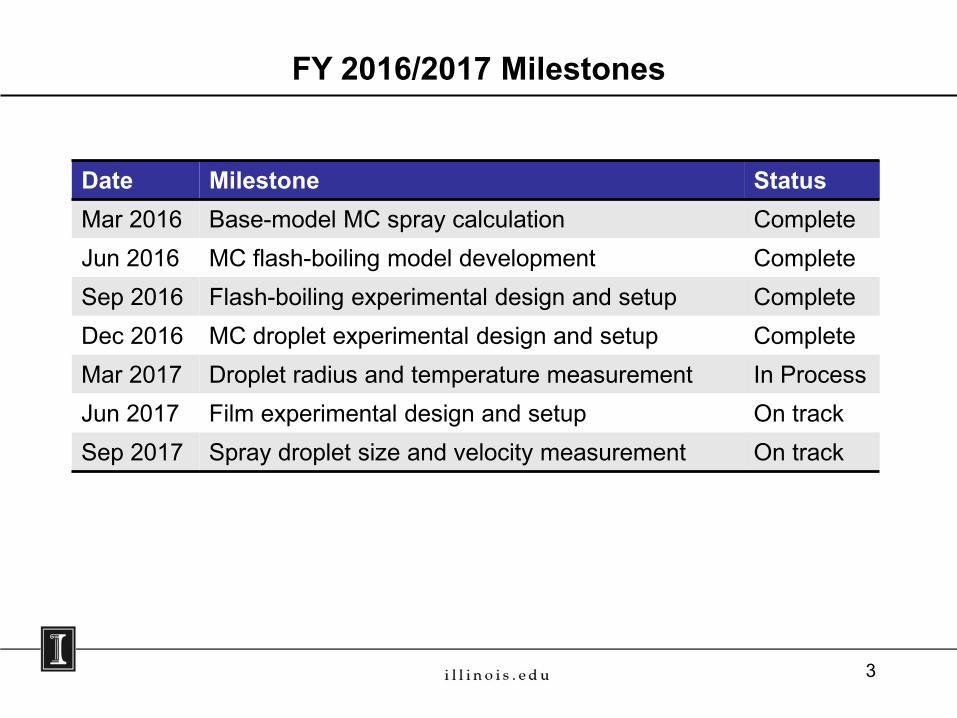
FY 2016/2017 Milestones
Date Milestone StatusMar 2016 Base-model MC spray calculation CompleteJun 2016 MC flash-boiling model development CompleteSep 2016 Flash-boiling experimental design and setup CompleteDec 2016 MC droplet experimental design and setup CompleteMar 2017 Droplet radius and temperature measurement In ProcessJun 2017 Film experimental design and setup On trackSep 2017 Spray droplet size and velocity measurement On track
3
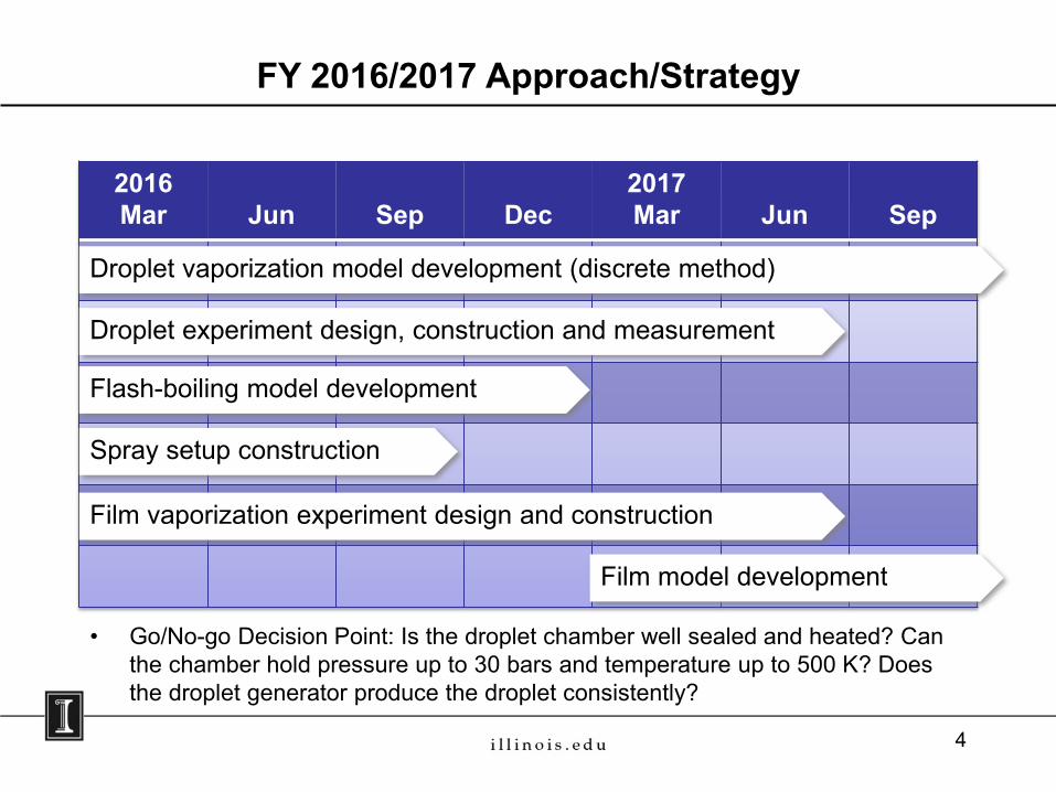
• Go/No-go Decision Point: Is the droplet chamber well sealed and heated? Can the chamber hold pressure up to 30 bars and temperature up to 500 K? Does the droplet generator produce the droplet consistently?
FY 2016/2017 Approach/Strategy
2016Mar Jun Sep Dec
2017Mar Jun Sep
Droplet vaporization model development (discrete method)
Droplet experiment design, construction and measurement
Flash-boiling model development
Spray setup construction
Film vaporization experiment design and construction
Film model development
4
FY2016/2017 Technical Accomplishments
5
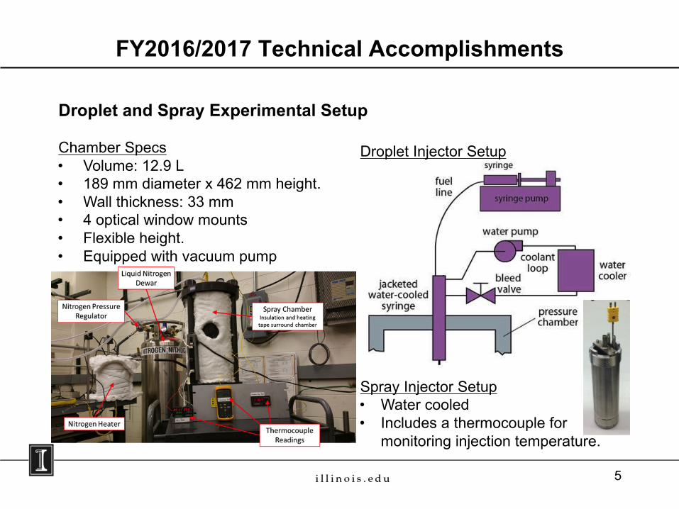
Droplet and Spray Experimental Setup
Chamber Specs• Volume: 12.9 L• 189 mm diameter x 462 mm height.• Wall thickness: 33 mm• 4 optical window mounts• Flexible height.• Equipped with vacuum pump
Droplet Injector Setup
Spray Injector Setup• Water cooled • Includes a thermocouple for
monitoring injection temperature.
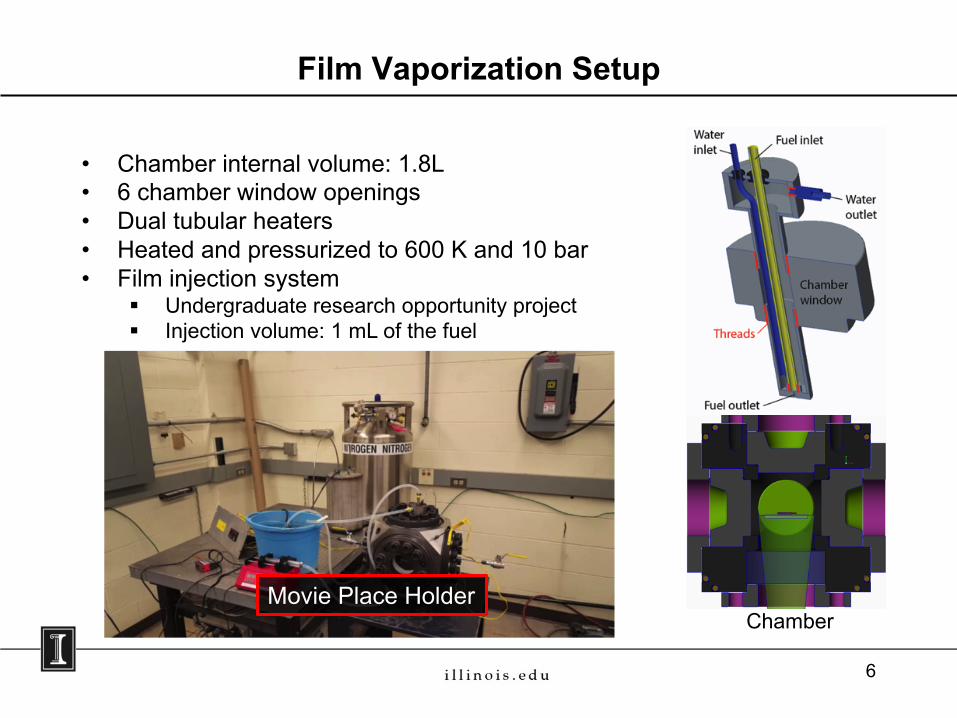
Film Vaporization Setup
• Chamber internal volume: 1.8L• 6 chamber window openings• Dual tubular heaters• Heated and pressurized to 600 K and 10 bar• Film injection system
§ Undergraduate research opportunity project§ Injection volume: 1 mL of the fuel
Chamber
6
Movie Place Holder
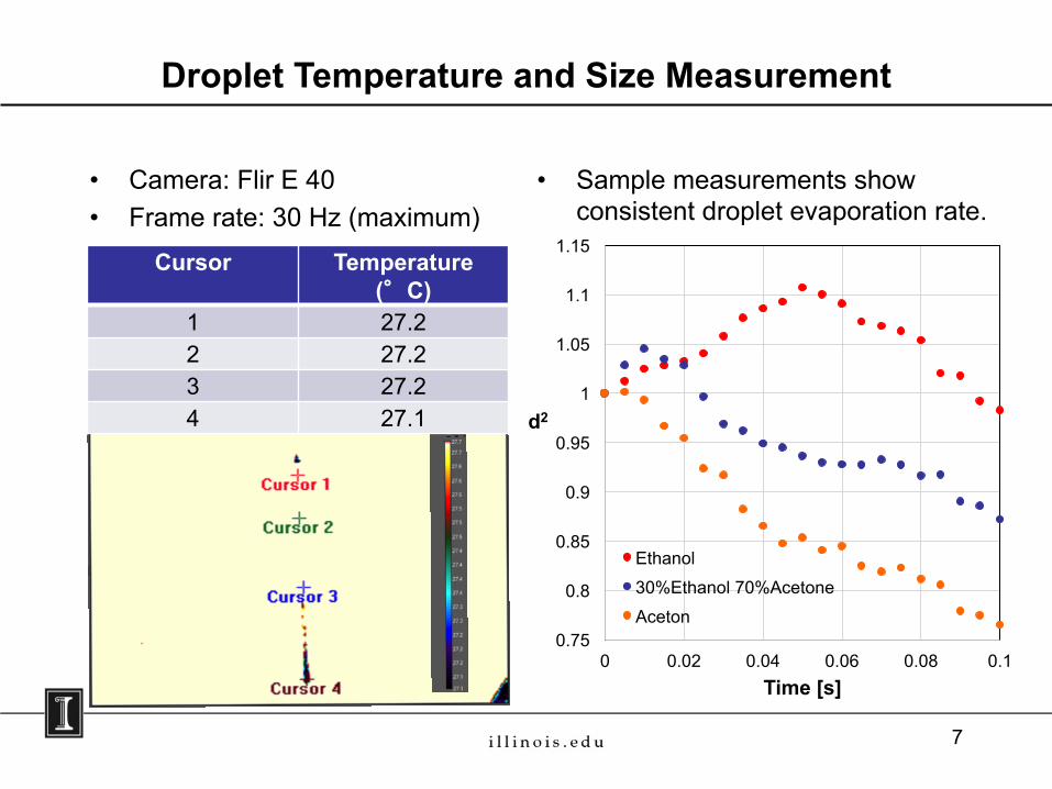
• Sample measurements show consistent droplet evaporation rate.
• Camera: Flir E 40• Frame rate: 30 Hz (maximum)
7
Droplet Temperature and Size Measurement
Cursor Temperature (°°C)
1 27.22 27.23 27.24 27.1
0.75
0.8
0.85
0.9
0.95
1
1.05
1.1
1.15
0 0.02 0.04 0.06 0.08 0.1Time [s]
Ethanol30%Ethanol 70%AcetoneAceton
d2
Spray Images
8 bar 10 bar 2 bar 5 barTinj = 70°C
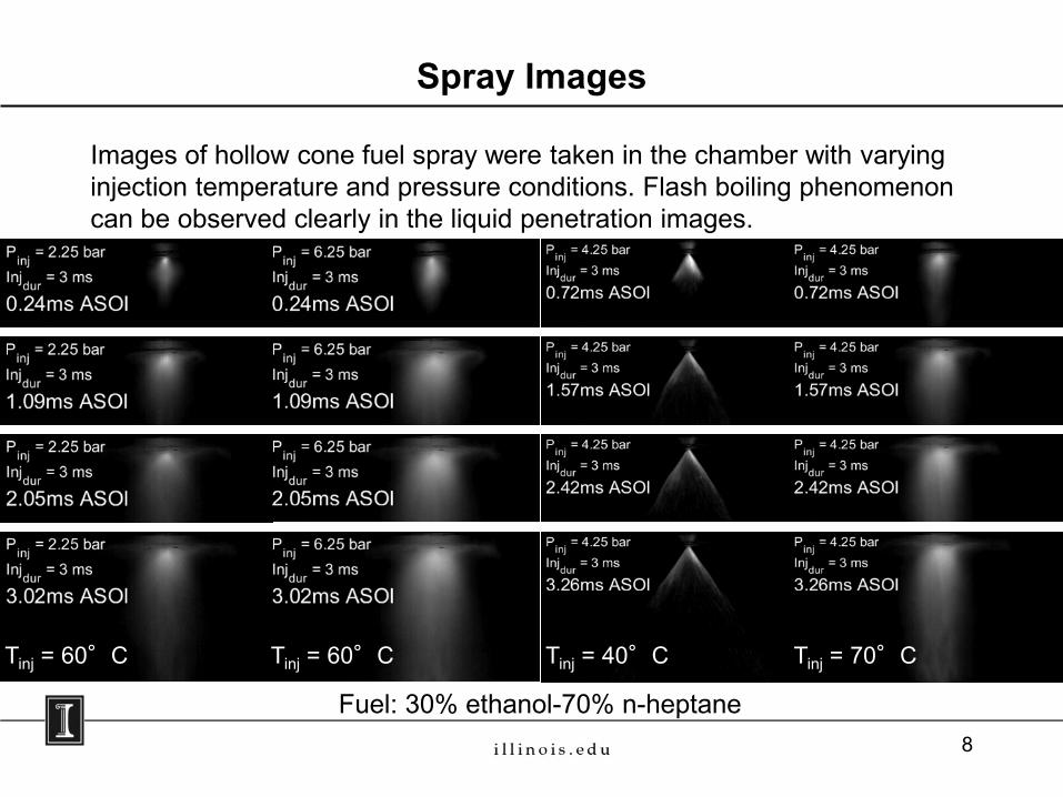
Images of hollow cone fuel spray were taken in the chamber with varying injection temperature and pressure conditions. Flash boiling phenomenon can be observed clearly in the liquid penetration images.
Tinj = 40°C
Fuel: 30% ethanol-70% n-heptane
Tinj = 60°CTinj = 60°C
8
Spray Characterization
8 bar 10 bar 2 bar 5 bar
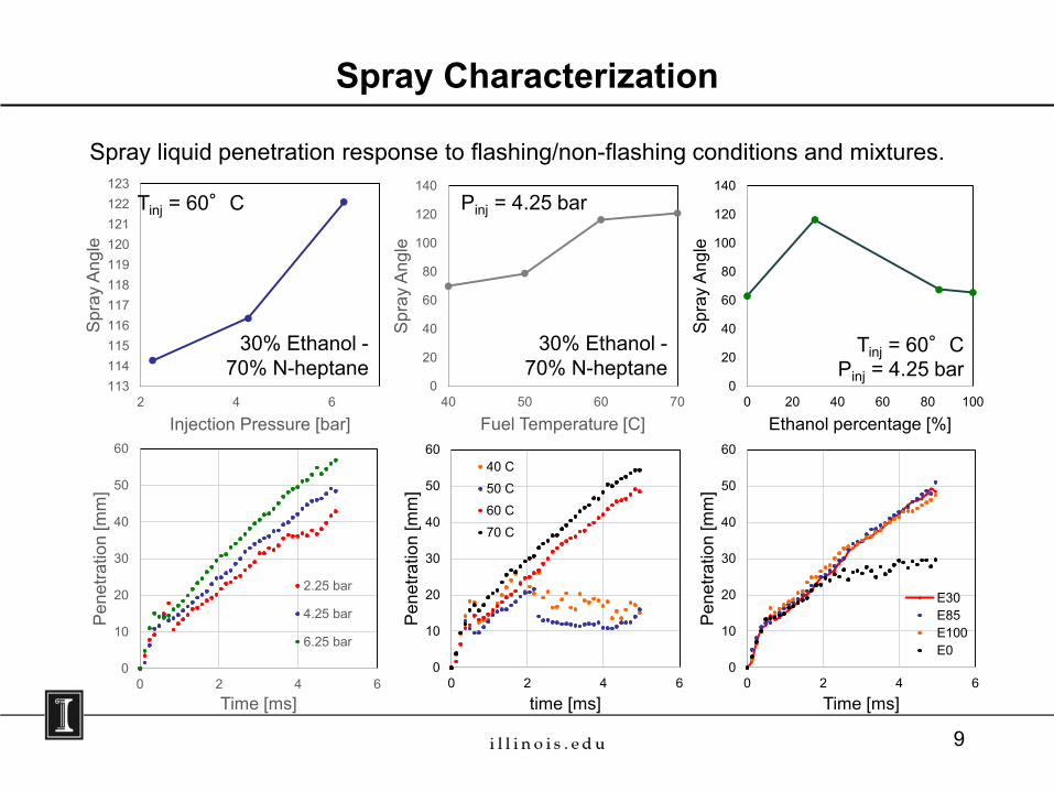
Spray liquid penetration response to flashing/non-flashing conditions and mixtures.
0
10
20
30
40
50
60
0 2 4 6
Pen
etra
tion
[mm
]
Time [ms]
2.25 bar
4.25 bar
6.25 bar
113114115116117118119120121122123
2 4 6
Spr
ay A
ngle
Injection Pressure [bar]
0
20
40
60
80
100
120
140
40 50 60 70S
pray
Ang
leFuel Temperature [C]
0
10
20
30
40
50
60
0 2 4 6
Pen
etra
tion
[mm
]
time [ms]
40 C50 C60 C70 C
0
10
20
30
40
50
60
0 2 4 6
Pen
etra
tion
[mm
]Time [ms]
E30E85E100E0
0
20
40
60
80
100
120
140
0 20 40 60 80 100
Spr
ay A
ngle
Ethanol percentage [%]
30% Ethanol -70% N-heptane
30% Ethanol -70% N-heptane
Tinj = 60°CPinj = 4.25 bar
Tinj = 60°C Pinj = 4.25 bar
9
Hollow Cone Flash Boiling Model vs. Observation
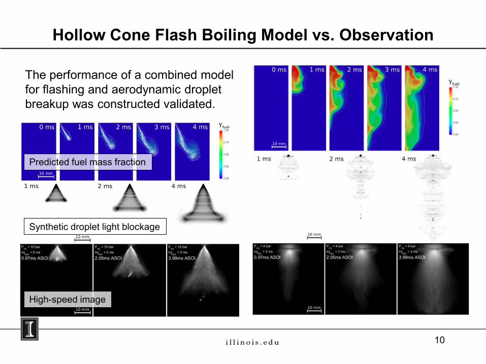
The performance of a combined model for flashing and aerodynamic droplet breakup was constructed validated.
Predicted fuel mass fraction
Synthetic droplet light blockage
High-speed image
10
Droplet liquid phase model• 1-D FVM
– Moving grid without cell deactivation– Degrade to 0-D (infinite diffusion model) when liquid is near-
depletion• Quasi 1-D model
– Tracks the difference between surface state and mean stateFluid properties and VLE• Peng-Robinson EOS• Proven thermal and transport property models for mixture• Easy to find the input parameters
– Only needs pure fluid parameters– All parameters can be easily found from either literature or public
databases
Major Features of the New Evaporation Model
11
12
Droplet Model Validation
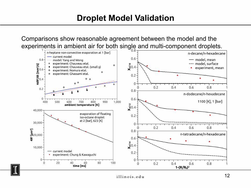
Comparisons show reasonable agreement between the model and the experiments in ambient air for both single and multi-component droplets.
ANL Flash-boiling Model Development
• Run Eulerian simulation of internal and near-nozzle flow• Capture phase change under flashing condition• Create a map file at nozzle exit that provides necessary inputs for spray
simulation• Utilize the map file (one-way spray modeling)to run Lagrangian spray
simulations• Capture phase change due to convective heating and/or flashing in
Lagrangian framework• Spray simulation framework: CONVERGE v2.3• Fuel injector: Spray G ECN• Compare Rate-Of-Injection (ROI) and one-way approaches
13
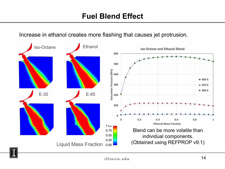
Fuel Blend Effect
Increase in ethanol creates more flashing that causes jet protrusion.
Liquid Mass Fraction
Iso-Octane Ethanol
E-30 E-85
Blend can be more volatile than individual components.
(Obtained using REFPROP v9.1)
14
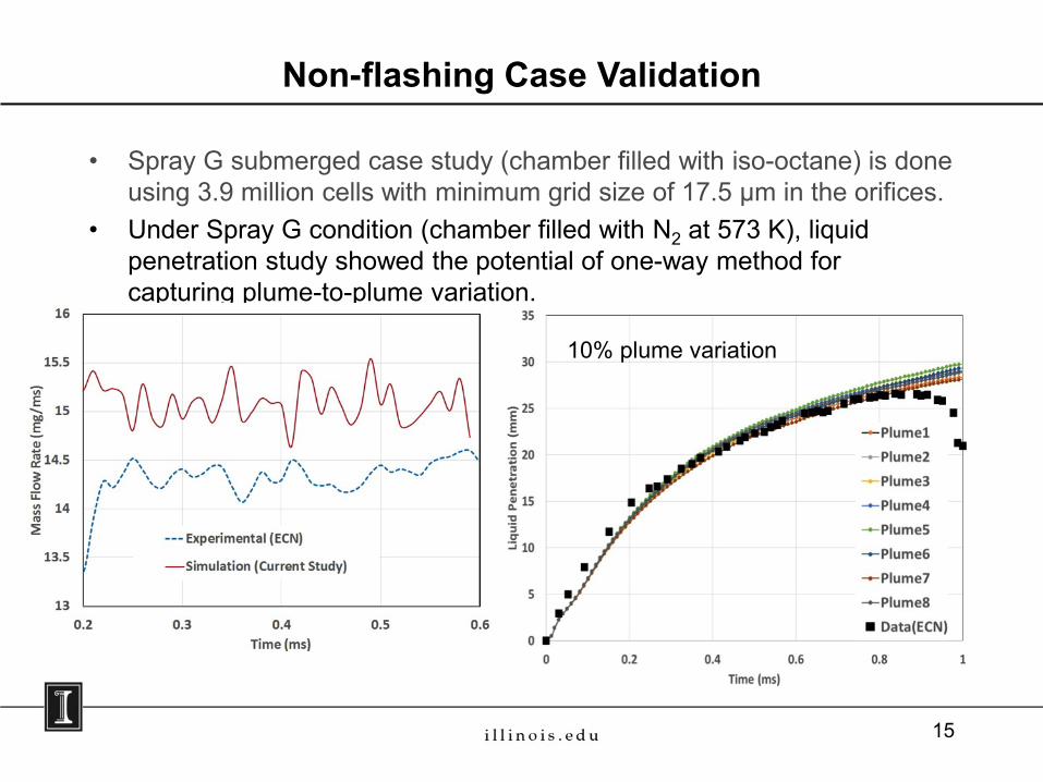
Non-flashing Case Validation
• Spray G submerged case study (chamber filled with iso-octane) is done using 3.9 million cells with minimum grid size of 17.5 µm in the orifices.
• Under Spray G condition (chamber filled with N2 at 573 K), liquid penetration study showed the potential of one-way method for capturing plume-to-plume variation.
10% plume variation
15
• This project is a new start.
Responses to Previous Year Reviewers’ Comments
16
• Develop multi-component flash-boiling model and integrate into current high-fidelity VOF framework.
Partnership/Collaboration
17
Remaining Challenges and Barriers
• Secure proper lasers to perform laser diagnostics for fuel characterization.
• Obtain high temporal resolution image for optical temperature measurement of multi-component fuel droplet.
18

Proposed Future Work
• Ongoing: - Experimental measurement of fuel droplet composition (GC/MS, LIEF)- Flash boiling model
Develop a more robust phase change model for cavitation and flashing Compare ROI and 1-way predictions for other conditions In-depth analysis of moving needle transients Further development in blended fuel flashing simulations
- Droplet and film model development/validation using the discrete method
• [Q3 Milestone] Design and implement of film vaporization system - Setup high-speed imaging and other optics system
• [Q4 Milestone] Experimental measurements of flash boiling spray- Droplet sizing (PDA, PDS), composition evolution (LIEF), and temperature
evolution (2-color LIF)
Any proposed future work is subject to change based on funding levels
19
Summary
• Experimental setup for multi-component fuel vaporization for the following studies were completed:– Droplet– Spray
• Film experiment setup is on track to complete during FY2017• Fuel droplet radius and temperature measurements have been
obtained; composition measurement is ongoing• Flash-boiling model development showed homogeneous relaxation
model is reasonable for GDI applications. Good agreement with data was observed for ROI and 1-way simulations, where 1-way has the ability to capture plume-to-plume variations
• Droplet model performed well against historical data for multi-component fuel blend
20

Thank You
Questions?
21
22
BACKUP SLIDES
23
24
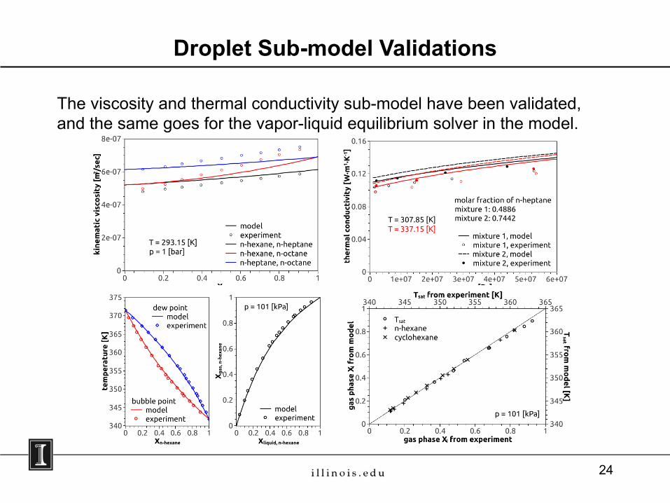
Droplet Sub-model Validations
The viscosity and thermal conductivity sub-model have been validated, and the same goes for the vapor-liquid equilibrium solver in the model.