Embed Size (px)
Citation preview
Manning AirAlert-96d Gas Monitor 19546 AIRALERT96D 07/09 Prelim REVC Copyright © 2009 Honeywell Analytics. All Rights Reserved. 1
This work contains valuable, confidential, and proprietary information. Disclosure, use or reproduction outside of Honeywell Inc. is prohibited except as authorized in writing.
This unpublished work is protected by the laws of the United States and other countries.
Honeywell Confidential & Proprietary
Release C Draft
07/09
Multi-Channel Gas Monitoring System
Manning AirAlertTM96d Instruction and Installation Manual

Manning AirAlert-96d Gas Monitor 19546 AIRALERT96D 07/09 Prelim REVC Copyright © 2009 Honeywell Analytics. All Rights Reserved. 2
Notices and Trademarks Copyright 2009 by Honeywell International Inc.
Release C July 2009
While this information is presented in good faith and believed to be accurate, Honeywell disclaims the implied warranties of merchantability and fitness for a particular purpose and makes no express warranties except as may be stated in its written agreement with and for its customers.
In no event is Honeywell liable to anyone for any indirect, special or consequential damages. The information and specifications in this document are subject to change without notice.
Manning is a registered trademark of Honeywell International Inc.
Other brand or product names are trademarks of their respective owners.
Honeywell Analytics 405 Barclay Blvd. Lincolnshire, IL 60069 USA
1-800-538-0363
About This Document World Wide Web The following Honeywell web sites may be of interest.
Honeywell Organization WWW Address (URL)
Corporate www.honeywell.com
Honeywell Analytics www.honeywellanalytics.com
Manning Gas Detection www.manningsystems.com
Telephone Contact us by telephone at the numbers listed below.
Organization Phone Number
United States Honeywell Analytics Inc. 1-800-538-0363 1-913-712-5576 1-913-712-5580 Fax
Canada Honeywell Analytics Inc. 1-888-749-8878
Europe Honeywell PACE +44 (0)1202 676161
Asia Pacific Honeywell Asia Pacific Inc. +82 (0)2 2025 0307
Middle East Honeywell Analytics Inc. +971 4 3458 338
Sales Information Contact us at [email protected]
Symbol Definitions The following table lists those symbols used in this document to denote certain conditions.
Symbol Definition
ATTENTION: Identifies information that requires special consideration.
TIP: Identifies advise or hints for the user, often in terms of performing a task.
REFERENCE-EXTERNAL: Identifies an additional source of information outside of this bookset.
REFERENCE-INTERNAL: Identifies an additional source of information within this bookset.
WARNING: Indicates a potentially hazardous situation, which, if not avoided, could result in injury or death.
Manning AirAlert-96d Gas Monitor 19546 AIRALERT96D 07/09 Prelim REVC Copyright © 2009 Honeywell Analytics. All Rights Reserved. 3
Manning AirAlert-96d Gas Monitor 19546 AIRALERT96D 07/09 Prelim REVC Copyright © 2009 Honeywell Analytics. All Rights Reserved. 4
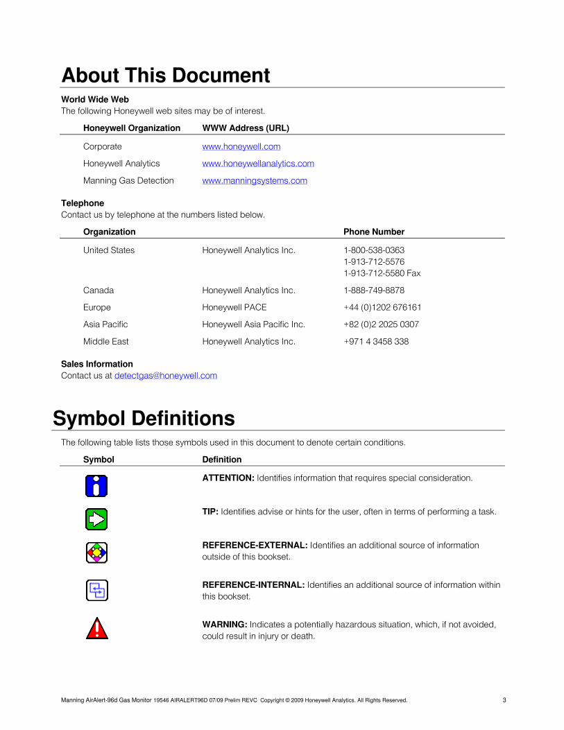
Contents Serial number:
Section Title Page
1 Introduction 6 A Safety Information — Read First 6 B Getting Started 6 2 Installation 7 A Guidelines 7 B Mounting Installation 7 3 Wiring 8 A Power 10 B Communication 10 C Relay Outputs 11 D Jumper Instructions 11 4 Initial Startup 12 A Datalogger (SDcard) 12 B User Interface 12 5 Operation 13 Normal, Single Tx, Debug, and Simulation Modes 13 6 Programming Menus 14
Controller Information 14 Sensor Information 14 Relay and Annunciator Information 14 Event Information 14
7 Configuration 15 A Main Menu 15 B Acquisition Mode 18 8 Specifications 24 9 Maintenance 24 Periodic Inspections and Calibration 24 Replacement Parts 24 Cleaning 24 Battery Disposal 24 10 Relay Module (optional) 25 11 Limited Warranty 27
Figure Title Page
1 Manning AirAlertTM96d 6 2 Installation 7 3 System Wiring 8 4 Sample Network Wiring 9 5 Power Wiring 10 6 Communications Wiring 10 7 Relay Outputs 11 8 Datalogger 12 9 User Interface 12 10 Tx Log 19 11 Manning AirAlertTM96d-RMS 25 12 Relay Module PCB 26
Introduction This manual has been prepared to help in the use and installation of the Manning AirAlert
TM96d Multi-Channel Gas
Monitoring System. This manual will convey the operating principles of the sensor, ensure proper installation, and demonstrate start-up and routine maintenance procedures.
ATTENTION: This manual must be carefully followed by all individuals who have or will have the responsibility for using or servicing the Manning AirAlertTM96d gas monitor. Warranties made by
Honeywell Analytics with respect to this equipment will be voided if the equipment is not used and serviced in accordance with the instructions in this manual. If in doubt about a procedure, please contact Honeywell Analytics before proceeding.
Manning AirAlert-96d Gas Monitor 19546 AIRALERT96D 07/09 Prelim REVC Copyright © 2009 Honeywell Analytics. All Rights Reserved. 5
1 Introduction
Warning • Warning: To prevent ignition of flammable or combustible atmospheres, disconnect power before servicing.
To ensure your personal safety, read “Safety Information” (below) before you use the controller.
• Do not use the controller if it is damaged. Before you use the controller, inspect the case.
The Manning AirAlertTM96d system sets new standards in gas detection and in the measurement of environmental parameters. • If the controller is damaged or something is
missing, contact Honeywell Analytics immediately.
Acting as the nerve center of a modular gas detection network, the Manning AirAlertTM96d provides continuous monitoring of up to 96 connected units on three distinct channels.
To avoid possible damage to the controller:
• Do not expose the controller to electrical shock and/or severe continuous mechanical shock.
The Manning AirAlertTM96d provides a full array of displays. At a glance, it is possible to determine the status of the entire network. Field modifications are straightforward. A menu driven program allows for minor fine-tuning of the sequence of operation all the way to the reconfiguration of the entire network.
• Do not attempt to disassemble, adjust, or service the controller unless instructions for that procedure are contained in the manual and/or that part is listed as a replacement part. Use only Manning replacement parts. Since no two projects are alike, the Manning
AirAlertTM96d is designed to be highly customized. Combined with ease of installation, this unit represents the most affordable gas monitoring solution for institutional, commercial and light industrial applications.
The controller Warranty could be voided if customer personnel or third parties damage the controller during repair attempts.
B Getting Started For more advanced applications, the Manning AirAlertTM96d controller provides datalogging capacity within a cast aluminum enclosure. The perfect solution for even the most complex of industrial applications.
Intended Use
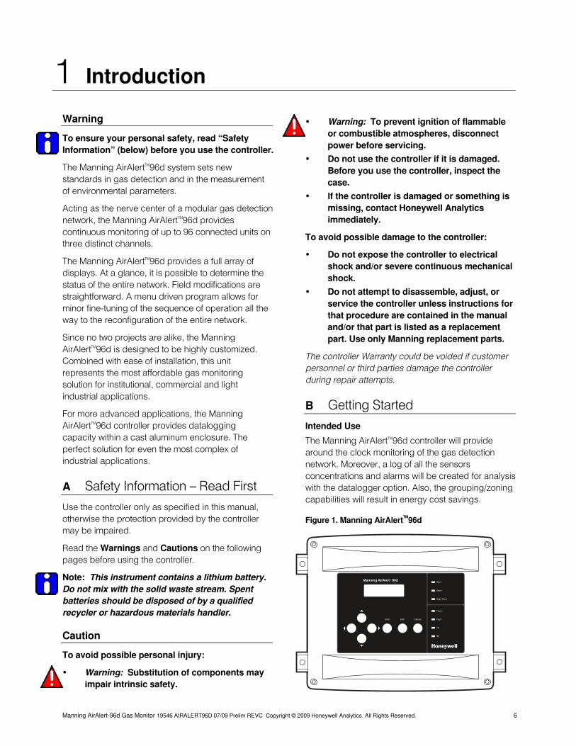
The Manning AirAlertTM96d controller will provide around the clock monitoring of the gas detection network. Moreover, a log of all the sensors concentrations and alarms will be created for analysis with the datalogger option. Also, the grouping/zoning capabilities will result in energy cost savings.
A Safety Information — Read First
Use the controller only as specified in this manual, otherwise the protection provided by the controller may be impaired.
Figure 1. Manning AirAlertTM96d
Manning AirAlert-96d Gas Monitor 19546 AIRALERT96D 07/09 Prelim REVC Copyright © 2009 Honeywell Analytics. All Rights Reserved. 6
Read the Warnings and Cautions on the following pages before using the controller.
Note: This instrument contains a lithium battery. Do not mix with the solid waste stream. Spent batteries should be disposed of by a qualified recycler or hazardous materials handler.
Caution
To avoid possible personal injury:
• Warning: Substitution of components may impair intrinsic safety.
Manning AirAlert 96dWarn
Alarm
High Alarm
Fault
Power
Enter ESC Silence
TX
RX
2 Installation
Manning AirAlert-96d Gas Monitor 19546 AIRALERT96D 07/09 Prelim REVC Copyright © 2009 Honeywell Analytics. All Rights Reserved. 7
A Guidelines These guidelines must be strictly observed to assure that the equipment will work properly. If they are not applied, Honeywell Analytics will not recognize any liability in case of improper operation.
• Make sure to locate all units easily accessible for proper service.
• Avoid any location where units could be subject to vibrations.
• Avoid any location close to any electro-magnetic interference.
• Avoid any location where there are large temperature swings.
• Verify local requirements and existing regulations, which may affect the choice of location.
Warning
A cable with more than one pair of wires is unacceptable for communication use.
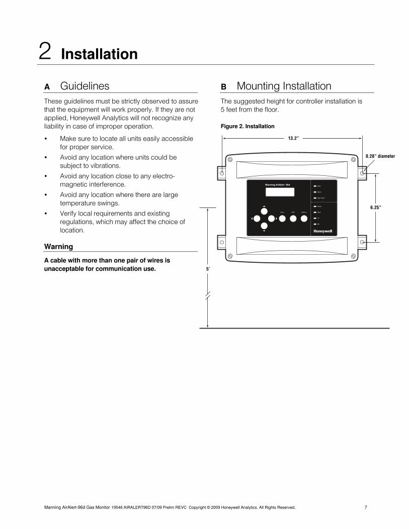
B Mounting Installation The suggested height for controller installation is 5 feet from the floor.
Figure 2. Installation
Manning AirAlert 96dWarn
Alarm
High Alarm
Fault
Power
Enter ESC Silence
TX
RX
13.2”
0.28” diameter
6.25”
5’

3 Wiring
Figure 3. System Wiring
Warn
Alarm
High Alarm
Power
Fault
TX
RX
RC
R
EO
L4
RC
RE
OL
3
RC
R
EO
L2
A1 B1 SHLDA2 B2V+ V- V+ V- SHLD A3 B4B3 A4
System status LEDs
NC
NO
NC
NO
J3
J7
J26
J25
NO NC NO NC
Normallyopen
Normallyclosed
3+54+6
1+32+4
6 4 2
5 3 1
Previous
J22
J23
J24
In Out
Relay 4
Relay 3
Relay 1 Relay 2End-of-linejumper position
RC
R
EO
L1
Pushbutton
Relay Outputs (J3-J7-J25-J26) 5A, 30 Vdc or 120 Vac (resistive load)
Next
Channel 2
Channel 1
Channel 4
Channel 3
SD card datalogger
Power Requirements (J22): Communication Requirements (J23 - J24):
• 24 Vdc, 500 mA • 24 AWG twisted pair, shielded (Belden 9841 or equivalent)
• 14 AWG, 2 conductor, stranded cable (Belden 5100UE or equivalent)
• Network can be up to 2,000 feet per channel
• Avoid “T-taps” if possible • Up to 10 sensors per power supply • Do not exceed 65 feet per T-tap • Up to 1,000 feet max power cable length per power supply • Do not exceen 130 feet total of all T-taps • Larger power cable and/or additional power supplies
may be required for longer cable runs and/or increased number of sensors
• Communication wire shield must be connected to shield terminal(s) of controller (J23-J24)
• Channels 1-2-3: Modbus protocol — Communicates only with Modbus devices Contact Honeywell Analytics for help with all power requirements.
• Channel 4: Modbus output only — No sensor can be connected to Channel 4
Manning AirAlert-96d Gas Monitor 19546 AIRALERT96D 07/09 Prelim REVC Copyright © 2009 Honeywell Analytics. All Rights Reserved. 8
3 Wiring continued
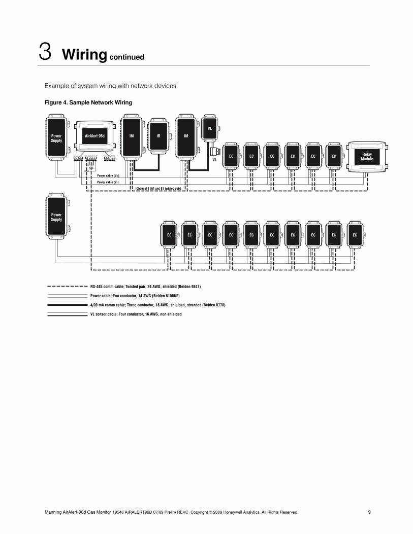
Example of system wiring with network devices:
Figure 4. Sample Network Wiring
EC EC EC EC EC EC
IRIM IMPowerSupply
RelayModule
AirAlert 96d
A1 B1 SHLDA2 B2V+ V- V+ V- SHLD A3 B4B3 A4
VL
VL
Power cable (V+)
Power cable (V-)
Channel 1 (A1 and B1 twisted pair)
EC EC EC ECEC EC EC EC EC EC
PowerSupply
RS-485 comm cable; Twisted pair, 24 AWG, shielded (Belden 9841)
Power cable; Two conductor, 14 AWG (Belden 5100UE)
4/20 mA comm cable; Three conductor, 18 AWG, shielded, stranded (Belden 8770)
VL sensor cable; Four conductor, 16 AWG, non-shielded
Manning AirAlert-96d Gas Monitor 19546 AIRALERT96D 07/09 Prelim REVC Copyright © 2009 Honeywell Analytics. All Rights Reserved. 9
3 Wiring continued
A Power
Manning AirAlert-96d Gas Monitor 19546 AIRALERT96D 07/09 Prelim REVC Copyright © 2009 Honeywell Analytics. All Rights Reserved. 10
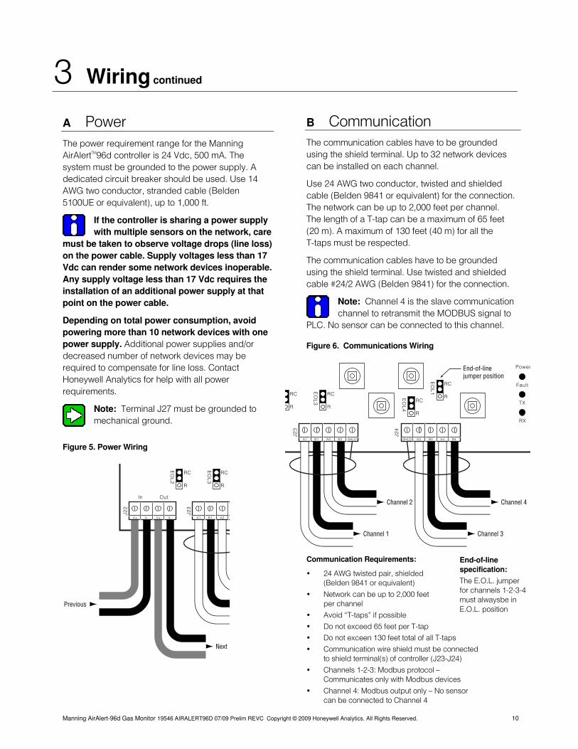
The power requirement range for the Manning AirAlertTM96d controller is 24 Vdc, 500 mA. The system must be grounded to the power supply. A dedicated circuit breaker should be used. Use 14 AWG two conductor, stranded cable (Belden 5100UE or equivalent), up to 1,000 ft.
If the controller is sharing a power supply with multiple sensors on the network, care
must be taken to observe voltage drops (line loss) on the power cable. Supply voltages less than 17 Vdc can render some network devices inoperable. Any supply voltage less than 17 Vdc requires the installation of an additional power supply at that point on the power cable.
Depending on total power consumption, avoid powering more than 10 network devices with one power supply. Additional power supplies and/or decreased number of network devices may be required to compensate for line loss. Contact Honeywell Analytics for help with all power requirements.
Note: Terminal J27 must be grounded to mechanical ground.
Figure 5. Power Wiring
B Communication The communication cables have to be grounded using the shield terminal. Up to 32 network devices can be installed on each channel.
Use 24 AWG two conductor, twisted and shielded cable (Belden 9841 or equivalent) for the connection. The network can be up to 2,000 feet per channel. The length of a T-tap can be a maximum of 65 feet (20 m). A maximum of 130 feet (40 m) for all the T-taps must be respected.
The communication cables have to be grounded using the shield terminal. Use twisted and shielded cable #24/2 AWG (Belden 9841) for the connection.
Note: Channel 4 is the slave communication channel to retransmit the MODBUS signal to
PLC. No sensor can be connected to this channel.
Figure 6. Communications Wiring
RC
R
EO
L3
RC
R
EO
L2
A1 B1 A2V+ V- V+ V-
Previous
J22
J23
In Out
Next
Power
Fault
TX
RX
RC
R
EO
L4
RC
R
EO
L3
RC
R
A1 B1 SHLDA2 B2 SHLD A3 B4B3 A4
J23
J24
End-of-linejumper position
RC
R
EO
L1
Channel 2
Channel 1
Channel 4
Channel 3
Communication Requirements: End-of-line specification:
The E.O.L. jumper for channels 1-2-3-4 must alwaysbe in E.O.L. position
• 24 AWG twisted pair, shielded (Belden 9841 or equivalent)
• Network can be up to 2,000 feet per channel
• Avoid “T-taps” if possible
• Do not exceed 65 feet per T-tap
• Do not exceen 130 feet total of all T-taps
• Communication wire shield must be connected to shield terminal(s) of controller (J23-J24)
• Channels 1-2-3: Modbus protocol — Communicates only with Modbus devices
• Channel 4: Modbus output only — No sensor can be connected to Channel 4
3 Wiring continued
C Relay Outputs
Manning AirAlert-96d Gas Monitor 19546 AIRALERT96D 07/09 Prelim REVC Copyright © 2009 Honeywell Analytics. All Rights Reserved. 11
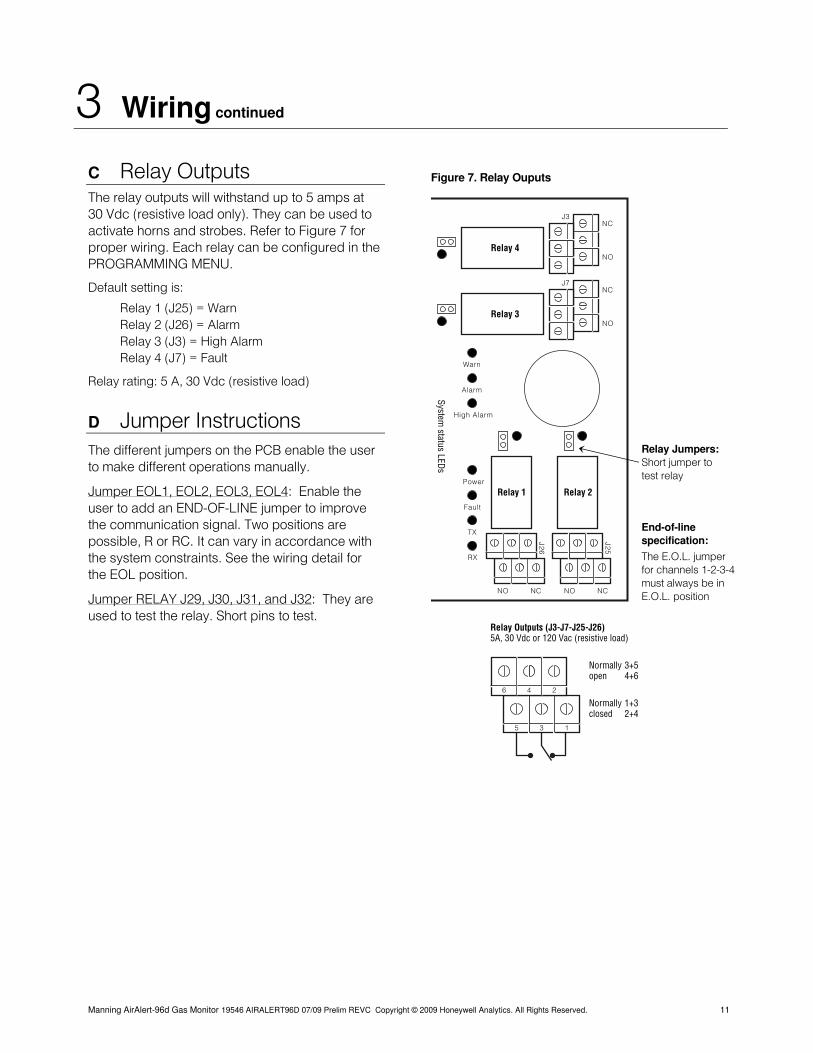
The relay outputs will withstand up to 5 amps at 30 Vdc (resistive load only). They can be used to activate horns and strobes. Refer to Figure 7 for proper wiring. Each relay can be configured in the PROGRAMMING MENU.
Default setting is:
Relay 1 (J25) = Warn Relay 2 (J26) = Alarm Relay 3 (J3) = High Alarm Relay 4 (J7) = Fault
Relay rating: 5 A, 30 Vdc (resistive load)
D Jumper Instructions The different jumpers on the PCB enable the user to make different operations manually.
Jumper EOL1, EOL2, EOL3, EOL4: Enable the user to add an END-OF-LINE jumper to improve the communication signal. Two positions are possible, R or RC. It can vary in accordance with the system constraints. See the wiring detail for the EOL position.
Jumper RELAY J29, J30, J31, and J32: They are used to test the relay. Short pins to test.
Figure 7. Relay Ouputs
Warn
Alarm
High Alarm
Power
Fault
TX
RX
System status LEDs
NC
NO
NC
NO
J3
J7
J26
J25
NO NC NO NC
Normallyopen
Normallyclosed
3+54+6
1+32+4
Relay 4
Relay 3
Relay 1 Relay 2
Relay Outputs (J3-J7-J25-J26) 5A, 30 Vdc or 120 Vac (resistive load)
End-of-line specification:
The E.O.L. jumper for channels 1-2-3-4 must always be in E.O.L. position
Relay Jumpers: Short jumper to test relay
6 4 2
5 3 1
4 Initial Startup
Be sure to connect the system as shown in the wiring detail before powering up the unit. Apply power to the controller and all network devices. Then remove the SHDN jumper to start the unit.
Manning AirAlert-96d Gas Monitor 19546 AIRALERT96D 07/09 Prelim REVC Copyright © 2009 Honeywell Analytics. All Rights Reserved. 12
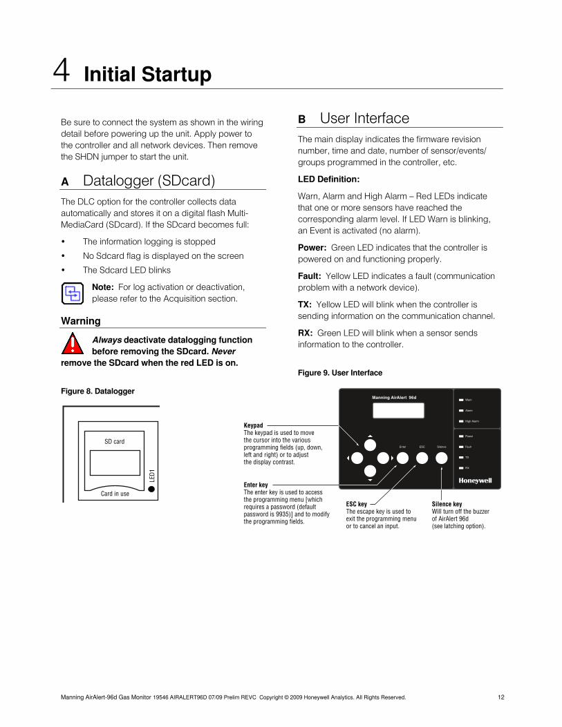
A Datalogger (SDcard) The DLC option for the controller collects data automatically and stores it on a digital flash Multi-MediaCard (SDcard). If the SDcard becomes full:
• The information logging is stopped
• No Sdcard flag is displayed on the screen
• The Sdcard LED blinks
Note: For log activation or deactivation, please refer to the Acquisition section.
Warning
Always deactivate datalogging function before removing the SDcard. Never
remove the SDcard when the red LED is on.
Figure 8. Datalogger
B User Interface The main display indicates the firmware revision number, time and date, number of sensor/events/ groups programmed in the controller, etc.
LED Definition:
Warn, Alarm and High Alarm — Red LEDs indicate that one or more sensors have reached the corresponding alarm level. If LED Warn is blinking, an Event is activated (no alarm).
Power: Green LED indicates that the controller is powered on and functioning properly.
Fault: Yellow LED indicates a fault (communication problem with a network device).
TX: Yellow LED will blink when the controller is sending information on the communication channel.
RX: Green LED will blink when a sensor sends information to the controller.
Figure 9. User Interface
LED1
Card in use
SD card
Manning AirAlert 96dWarn
Alarm
High Alarm
Fault
Power
Enter ESC Silence
TX
RX
Keypad The keypad is used to move the cursor into the various programming fields (up, down, left and right) or to adjust the display contrast.
Enter key The enter key is used to access the programming menu [which requires a password (default password is 9935)] and to modify the programming fields.
ESC keyThe escape key is used to exit the programming menu or to cancel an input.
Silence keyWill turn off the buzzer of AirAlert 96d (see latching option).
5 Operation
The available system operations are based on four different modes: normal mode, single Tx mode, debug mode, and simulation mode. These system modes enable the user to use, analyze, debug, and simulate actions that can be taken by the system. Password is needed to access the different programming menus. The system services might be interrupted by some menu operations.
A Normal Mode When the system is in Normal Mode, some values can be changed without interrupting the system service. After changing a value in the menu fields, the new value will take effect right after the user gets back to the MAIN MENU. The Normal Mode is the normal system operation.
Note: Entering the EVENT MENU will disable Event evaluation and reset their status —
during that time, the system is out of service until the user goes back to the MAIN MENU.
Normal Mode Menu
1 Tx Info
2 Groups
3 Events (block Event evaluation if acceded)
5 Copy
7 Network
Warning
Any actions taken in these menus reset the Event status.
Note: Displays details in the following pages.
B Single Tx Mode The Single Tx Mode doesn’t prevent Event evaluation. By entering this mode, the user is able to analyse one sensor at a time. Only the displayed device is interrogated by the controller, thus has its information updated.
C Debug Mode This mode is very helpful to evaluate the system, test the system operation without stopping any system services and calibrate the connected sensors. In fact, everything stays in operation except that no actions are taken by the Event. This way no relay is activated.
Note: If one of these modes is accessed, the system will automatically return to Normal
Mode after 15 minutes.
D Simulation Mode • The Simulation Mode deactivates information
update from the network communication.
• This mode simulates the gas concentration over associated scale range for each sensor, one after the other.
• The alarm level (A, B, C) are evaluated in accordance to the gas concentration simulated.
• Events are evaluated and actions are taken.
• During the simulation, the controller is unaware of the current status of the network device.
• Simulation Mode can be stopped in the TEST MENU at any time.
Note: Simulation Mode can be combined with any of the three previous ones (i.e.,
Normal Mode, Single Tx Mode, or Debug Mode). No other combinations are possible.
Manning AirAlert-96d Gas Monitor 19546 AIRALERT96D 07/09 Prelim REVC Copyright © 2009 Honeywell Analytics. All Rights Reserved. 13
6 Programming Menus
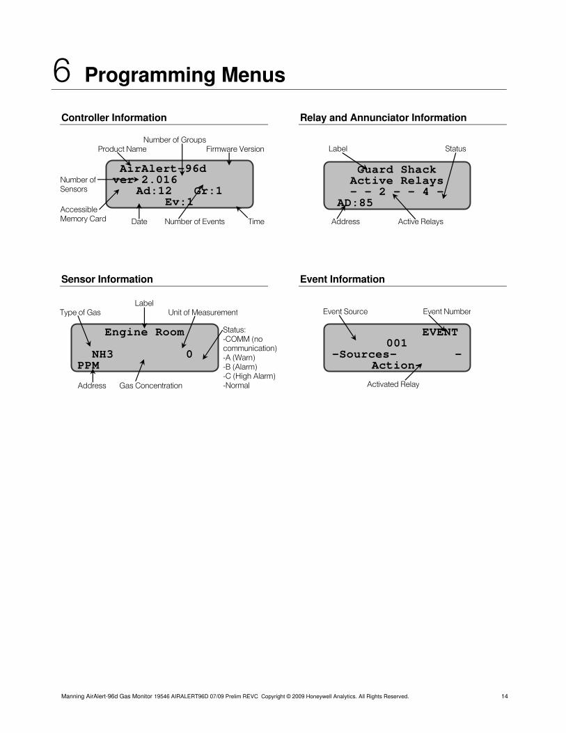
Controller Information
Sensor Information
Relay and Annunciator Information
Event Information
Number of Sensors Accessible Memory Card
AirAlert-96d ver 2.016
Ad:12 Gr:1 Ev:1
Date Number of Events Time
Number of Groups Product Name Firmware Version Label Status
Guard Shack Active Relays - - 2 - - 4 -
AD:85
Address Active Relays
Label Event Source Event Number Type of Gas Unit of Measurement
EVENT 001
-Sources- -Action-
Engine Room
Activated Relay
NH3 0 PPM
Status: -COMM (no communication) -A (Warn)
Address Gas Concentration
-B (Alarm) -C (High Alarm) -Normal
Manning AirAlert-96d Gas Monitor 19546 AIRALERT96D 07/09 Prelim REVC Copyright © 2009 Honeywell Analytics. All Rights Reserved. 14
7 Configuration
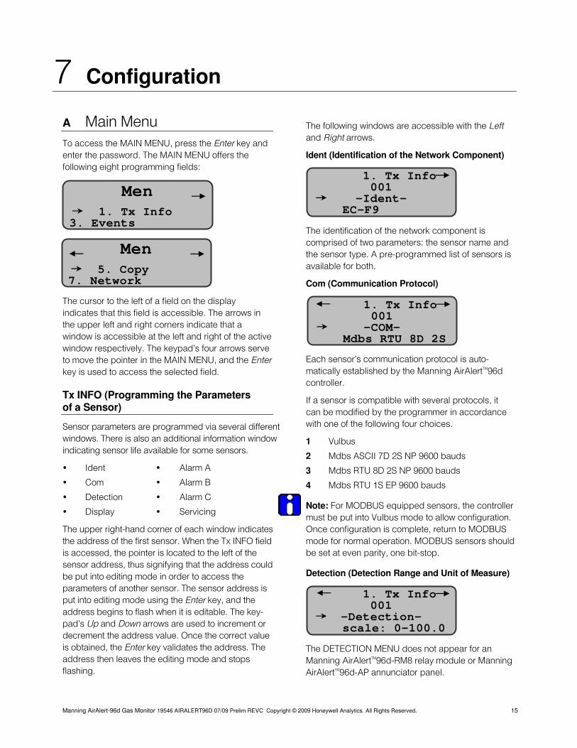
A Main Menu To access the MAIN MENU, press the Enter key and enter the password. The MAIN MENU offers the following eight programming fields:
The cursor to the left of a field on the display indicates that this field is accessible. The arrows in the upper left and right corners indicate that a window is accessible at the left and right of the active window respectively. The keypad’s four arrows serve to move the pointer in the MAIN MENU, and the Enter key is used to access the selected field.
Tx INFO (Programming the Parameters of a Sensor)
Sensor parameters are programmed via several different windows. There is also an additional information window indicating sensor life available for some sensors.
• Ident • Alarm A
• Com • Alarm B
• Detection • Alarm C
• Display • Servicing
The upper right-hand corner of each window indicates the address of the first sensor. When the Tx INFO field is accessed, the pointer is located to the left of the sensor address, thus signifying that the address could be put into editing mode in order to access the parameters of another sensor. The sensor address is put into editing mode using the Enter key, and the address begins to flash when it is editable. The key-pad’s Up and Down arrows are used to increment or decrement the address value. Once the correct value is obtained, the Enter key validates the address. The address then leaves the editing mode and stops flashing.
The following windows are accessible with the Left and Right arrows.
Ident (Identification of the Network Component)
1. Tx Info 001
The identification of the network component is comprised of two parameters: the sensor name and the sensor type. A pre-programmed list of sensors is available for both.
Com (Communication Protocol)
Each sensor’s communication protocol is auto-matically established by the Manning AirAlertTM96d controller.
If a sensor is compatible with several protocols, it can be modified by the programmer in accordance with one of the following four choices.
1 Vulbus
2 Mdbs ASCII 7D 2S NP 9600 bauds
3 Mdbs RTU 8D 2S NP 9600 bauds
4 Mdbs RTU 1S EP 9600 bauds
Note: For MODBUS equipped sensors, the controller must be put into Vulbus mode to allow configuration. Once configuration is complete, return to MODBUS mode for normal operation. MODBUS sensors should be set at even parity, one bit-stop.
Detection (Detection Range and Unit of Measure)
The DETECTION MENU does not appear for an Manning AirAlertTM96d-RM8 relay module or Manning AirAlertTM96d-AP annunciator panel.
1. Tx Info 001
-Detection- scale: 0-100.0
-Ident- EC-F9
1. Tx Info 3. Events
Men
5. Copy 7. Network
Men
1. Tx Info 001 O-C M-
Mdbs RTU 8D 2S
Manning AirAlert-96d Gas Monitor 19546 AIRALERT96D 07/09 Prelim REVC Copyright © 2009 Honeywell Analytics. All Rights Reserved. 15
7 Configuration continued
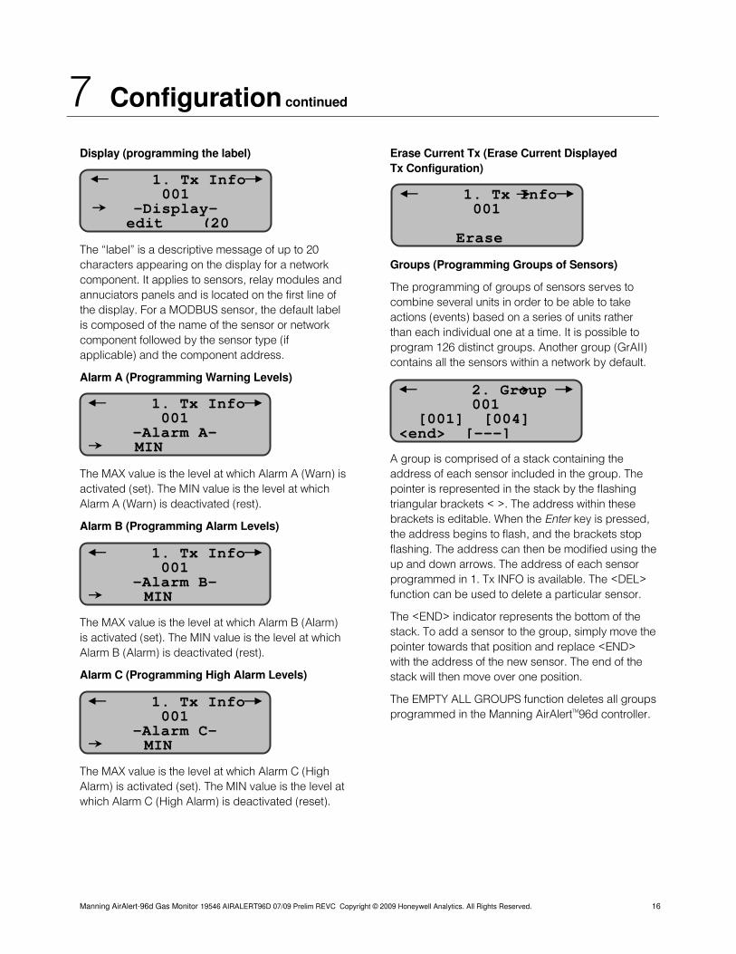
Display (programming the label)
The “label” is a descriptive message of up to 20 characters appearing on the display for a network component. It applies to sensors, relay modules and annuciators panels and is located on the first line of the display. For a MODBUS sensor, the default label is composed of the name of the sensor or network component followed by the sensor type (if applicable) and the component address.
Alarm A (Programming Warning Levels)
The MAX value is the level at which Alarm A (Warn) is activated (set). The MIN value is the level at which Alarm A (Warn) is deactivated (rest).
Alarm B (Programming Alarm Levels)
The MAX value is the level at which Alarm B (Alarm) is activated (set). The MIN value is the level at which Alarm B (Alarm) is deactivated (rest).
Alarm C (Programming High Alarm Levels)
The MAX value is the level at which Alarm C (High Alarm) is activated (set). The MIN value is the level at which Alarm C (High Alarm) is deactivated (reset).
Erase Current Tx (Erase Current Displayed Tx Configuration)
1. Tx Info 001
-Display-
Groups (Programming Groups of Sensors)
The programming of groups of sensors serves to combine several units in order to be able to take actions (events) based on a series of units rather than each individual one at a time. It is possible to program 126 distinct groups. Another group (GrAII) contains all the sensors within a network by default.
A group is comprised of a stack containing the address of each sensor included in the group. The pointer is represented in the stack by the flashing triangular brackets < >. The address within these brackets is editable. When the Enter key is pressed, the address begins to flash, and the brackets stop flashing. The address can then be modified using the up and down arrows. The address of each sensor programmed in 1. Tx INFO is available. The <DEL> function can be used to delete a particular sensor.
The <END> indicator represents the bottom of the stack. To add a sensor to the group, simply move the pointer towards that position and replace <END> with the address of the new sensor. The end of the stack will then move over one position.
The EMPTY ALL GROUPS function deletes all groups programmed in the Manning AirAlertTM96d controller.
1. Tx Info 001
-Alarm C- MIN
1. Tx Info 001
-Alarm B- MIN
1. Tx Info 001
-Alarm A- MIN
edit (20
1. Tx Info 001
Erase
2. Group 001
[001] [004] <end> [---]
Manning AirAlert-96d Gas Monitor 19546 AIRALERT96D 07/09 Prelim REVC Copyright © 2009 Honeywell Analytics. All Rights Reserved. 16
7 Configuration continued
Event (Programming Events)
Default event configuration (EVENT MENU):
• Relay #1 will be activated when alarm A is reached.
• Alarm B will trigger relay #2.
• The buzzer will also be activated for any sensors that reach alarm B.
• Relay #3 will be activated when alarm C is reached.
• Pressing the silence key will acknowledge the latched Events and silence the buzzer.
• Relay #4 will be activated for any fault status.
Event programming serves to define particular actions. The following specific windows are used for such programming:
• Action
• Delay (Condition 1) (Condition 2)
• Delete
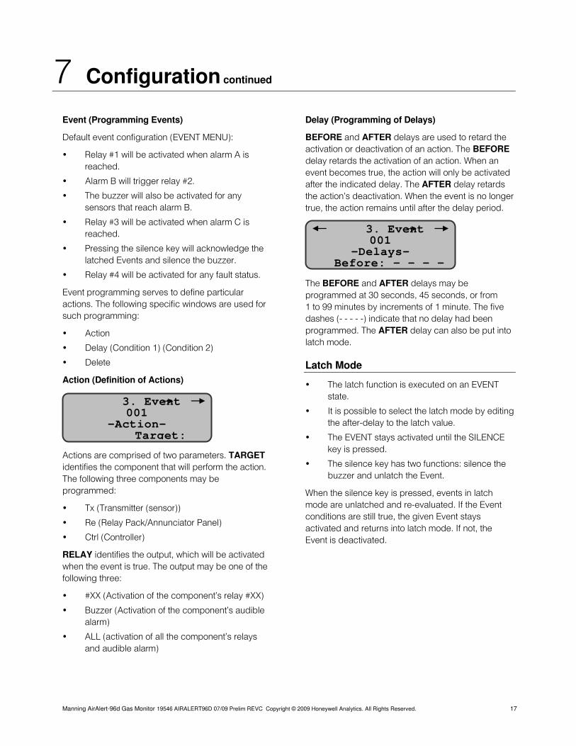
Action (Definition of Actions)
Actions are comprised of two parameters. TARGET identifies the component that will perform the action. The following three components may be programmed:
• Tx (Transmitter (sensor))
• Re (Relay Pack/Annunciator Panel)
• Ctrl (Controller)
RELAY identifies the output, which will be activated when the event is true. The output may be one of the following three:
• #XX (Activation of the component’s relay #XX)
• Buzzer (Activation of the component’s audible alarm)
• ALL (activation of all the component’s relays and audible alarm)
Delay (Programming of Delays)
BEFORE and AFTER delays are used to retard the activation or deactivation of an action. The BEFORE delay retards the activation of an action. When an event becomes true, the action will only be activated after the indicated delay. The AFTER delay retards the action’s deactivation. When the event is no longer true, the action remains until after the delay period.
3. Event 001
-Delays- Before: - - - -
The BEFORE and AFTER delays may be programmed at 30 seconds, 45 seconds, or from 1 to 99 minutes by increments of 1 minute. The five dashes (- - - - -) indicate that no delay had been programmed. The AFTER delay can also be put into latch mode.
Latch Mode
• The latch function is executed on an EVENT state. 3. Event
001 -Action-
• It is possible to select the latch mode by editing the after-delay to the latch value.
Target: • The EVENT stays activated until the SILENCE key is pressed.
• The silence key has two functions: silence the buzzer and unlatch the Event.
When the silence key is pressed, events in latch mode are unlatched and re-evaluated. If the Event conditions are still true, the given Event stays activated and returns into latch mode. If not, the Event is deactivated.
Manning AirAlert-96d Gas Monitor 19546 AIRALERT96D 07/09 Prelim REVC Copyright © 2009 Honeywell Analytics. All Rights Reserved. 17
7 Configuration continued
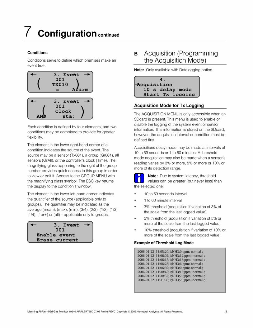
Conditions
Conditions serve to define which premises make an event true.
Each condition is defined by four elements, and two conditions may be combined to provide for greater flexibility.
The element in the lower right-hand corner of a condition indicates the source of the event. The source may be a sensor (Tx001), a group (Gr001), all sensors (GrAll), or the controller’s clock (Time). The magnifying glass appearing to the right of the group number provides quick access to this group in order to view or edit it. Access to the GROUP MENU with the magnifying glass symbol. The ESC key returns the display to the condition’s window.
The element in the lower left-hand corner indicates the quantifier of the source (applicable only to groups). The quantifier may be indicated as the average (mean), (max), (min), (3/4), (2/3), (1/2), (1/3), (1/4), (1or+) or (all) — applicable only to groups.
B Acquisition (Programming the Acquisition Mode) Note: Only available with Datalogging option.
3. Even 001
t
TX010 = Alarm ( )
4. Acquisition 10 s delay mode Start Tx logging
3. Event 001
Clock AND sta: ( )
3. Event 001
Enable event
Acquisition Mode for Tx Logging
The ACQUISITION MENU is only accessible when an SDcard is present. This menu is used to enable or disable the logging of the system event or sensor information. This information is stored on the SDcard, however, the acquisition interval or condition must be defined first.
Acquisitions delay mode may be made at intervals of 10 to 59 seconds or 1 to 60 minutes. A threshold mode acquisition may also be made when a sensor’s reading varies by 3% or more, 5% or more or 10% or more of its detection range.
Note: Due to system latency, threshold values can be greater (but never less) than
the selected one.
• 10 to 59 seconds interval
• 1 to 60 minute interval
• 3% threshold (acquisition if variation of 3% of the scale from the last logged value)
• 5% threshold (acquisition if variation of 5% or more of the scale from the last logged value)
• 10% threshold (acquisition if variation of 10% or more of the scale from the last logged value)
Erase current Example of Threshold Log Mode
2006-01-22 11:05:20;1;NH3;0;ppm;-normal-; 2006-01-22 11:06:02;1;NH3;12;ppm;-normal-; 2006-01-22 11:06:15;1;NH3;18;ppm;-normal-; 2006-01-22 11:06:28;1;NH3;6;ppm;-normal-; 2006-01-22 11:06:39;1;NH3;0;ppm;-normal-; 2006-01-22 11:30:45;1;NH3;15;ppm;-normal-; 2006-01-22 11:30:57;1;NH3;23;ppm;-normal-; 2006-01-22 11:31:08;1;NH3;20;ppm;-normal-;
Manning AirAlert-96d Gas Monitor 19546 AIRALERT96D 07/09 Prelim REVC Copyright © 2009 Honeywell Analytics. All Rights Reserved. 18
7 Configuration continued
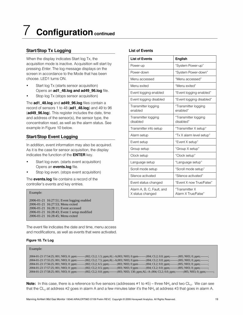
Start/Stop Tx Logging
When the display indicates Start log Tx, the acquisition mode is inactive. Acquisition will start by pressing Enter. The log message displays on the screen in accordance to the Mode that has been choose. LED1 turns ON.
• Start log Tx (starts sensor acquisition) Opens an ad1_48.log and ad49_96.log file. • Stop log Tx (stops sensor acquisition)
The ad1_48.log and ad49_96.log files contain a record of sensors 1 to 48 (ad1_48.log) and 49 to 96 (ad49_96.log). This register includes the date, time and address of the sensor(s), the sensor type, the concentration read, as well as the alarm status. See example in Figure 10 below.
Start/Stop Event Logging
In addition, event information may also be acquired. As it is the case for sensor acquisition, the display indicates the function of the ENTER key.
• Start log even. (starts event acquisition) Opens an events.log file. • Stop log even. (stops event acquisition)
The events.log file contains a record of the controller’s events and key entries.
The event file indicates the date and time, menu access and modifications, as well as events that were activated.
Figure 10. Tx Log
List of Events
List of Events English
Power-up “System Power-up”
Power-down “System Power-down”
Menu accessed “Menu accessed”
Menu exited “Menu exited”
Event logging enabled “Event logging enabled”
Event logging disabled “Event logging disabled”
Transmitter logging “Transmitter logging enabled enabled”
Transmitter logging “Transmitter logging disabled disabled”
Transmitter info setup “Transmitter X setup”
Alarm setup “Tx X alarm level setup”
Event setup “Event X setup”
Group setup “Group X setup”
Clock setup “Clock setup”
Language setup “Language setup”
Scroll mode setup “Scroll mode setup”
Silence activated “Silence activated”
Event status changed “Event X now True/False”
Alarm A, B, C, Fault, and “Transmitter X X status changed Alarm X True/False” Example:
2006-01-21 16:27:51; Event logging enabled 2006-01-21 16:27:53; Menu exited 2006-01-21 16:28:11; Event accessed 2006-01-21 16:28:43; Event 1 setup modified 2006-01-21 16:28:45; Menu exited
Example: 2004-01-23 17:54:25; 001; NH3; 0: ppm:--------;002; CL2; 1.5; ppm;AL:-A;003; NH3; 0 ppm--------;004; CL2; 0.0; ppm;--------;005; NH3; 0; ppm;--------; 2004-01-23 17:55:25; 001; NH3; 0: ppm:--------;002; CL2; 7.5; ppm;AL:-A;003; NH3; 0 ppm--------;004; CL2; 0.0; ppm;--------;005; NH3; 0; ppm;--------; 2004-01-23 17:56:25; 001; NH3; 0: ppm:--------;002; CL2; 6.5; ppm;--------;003; NH3; 0 ppm--------;004; CL2; 0.0; ppm;--------;005; NH3; 0; ppm;--------; 2004-01-23 17:57:25; 001; NH3; 0: ppm:--------;002; CL2; 0.5; ppm;--------;003; NH3; 0 ppm--------;004; CL2; 0.0; ppm;--------;005; NH3; 0; ppm;--------; 2004-01-23 17:58:25; 001; NH3; 0: ppm:--------;002; CL2; 0.0; ppm;--------;003; NH3; 130; ppm;AL:-A-;004; CL2; 0.0; ppm;--------;005; NH3; 0; ppm;--------;
Note: In this case, there is a reference to five sensors (addresses #1 to #5) — three NH3 and two CL2. We can see that the CL2 at address #2 goes in alarm A and a few minutes later it’s the NH3 at address #3 that goes in alarm A.
Manning AirAlert-96d Gas Monitor 19546 AIRALERT96D 07/09 Prelim REVC Copyright © 2009 Honeywell Analytics. All Rights Reserved. 19
7 Configuration continued
Copy (Transferring Data and Copying Parameters)
The COPY function serves to transfer data and copy parameters within the following windows:
• Configuration
• Parameters
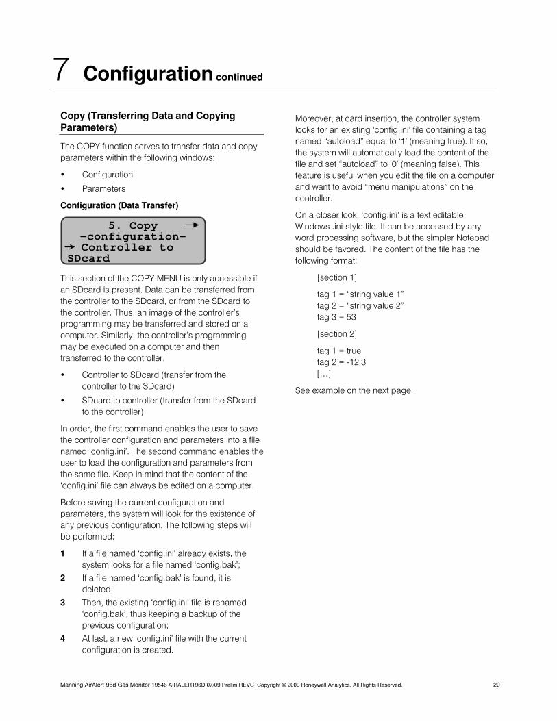
Configuration (Data Transfer)
This section of the COPY MENU is only accessible if an SDcard is present. Data can be transferred from the controller to the SDcard, or from the SDcard to the controller. Thus, an image of the controller’s programming may be transferred and stored on a computer. Similarly, the controller’s programming may be executed on a computer and then transferred to the controller.
• Controller to SDcard (transfer from the controller to the SDcard)
• SDcard to controller (transfer from the SDcard to the controller)
In order, the first command enables the user to save the controller configuration and parameters into a file named ‘config.ini’. The second command enables the user to load the configuration and parameters from the same file. Keep in mind that the content of the ‘config.ini’ file can always be edited on a computer.
Before saving the current configuration and parameters, the system will look for the existence of any previous configuration. The following steps will be performed:
1 If a file named ‘config.ini’ already exists, the system looks for a file named ‘config.bak’;
2 If a file named ‘config.bak’ is found, it is deleted;
3 Then, the existing ‘config.ini’ file is renamed ‘config.bak’, thus keeping a backup of the previous configuration;
4 At last, a new ‘config.ini’ file with the current configuration is created.
Moreover, at card insertion, the controller system looks for an existing ‘config.ini’ file containing a tag named “autoload” equal to ‘1’ (meaning true). If so, the system will automatically load the content of the file and set “autoload” to ‘0’ (meaning false). This feature is useful when you edit the file on a computer and want to avoid “menu manipulations” on the controller.
On a closer look, ‘config.ini’ is a text editable Windows .ini-style file. It can be accessed by any word processing software, but the simpler Notepad should be favored. The content of the file has the following format:
5. Copy
-configuration- Controller to SDcard
[section 1]
tag 1 = “string value 1” tag 2 = “string value 2” tag 3 = 53
[section 2]
tag 1 = true tag 2 = -12.3 […]
See example on the next page.
Manning AirAlert-96d Gas Monitor 19546 AIRALERT96D 07/09 Prelim REVC Copyright © 2009 Honeywell Analytics. All Rights Reserved. 20
7 Configuration continued
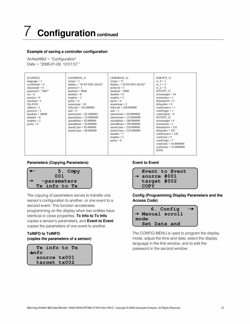
Example of saving a controller configuration
AirAlert96d = “Configuration” Date = “2006-01-09 13:51:57:”
Parameters (Copying Parameters)
The copying of parameters serves to transfer one sensor’s configuration to another, or one event to a second event. This function accelerates programming on the display when two entities have identical or close properties. Tx Info to Tx Info copies a sensor’s parameters, and Event to Event copies the parameters of one event to another.
TxINFO to TxINFO (copies the parameters of a sensor)
Event to Event
Config (Programming Display Parameters and the Access Code)
The CONFIG MENU is used to program the display mode, adjust the time and date, select the display language in the first window, and to edit the password in the second window.
[CONFIG] language = 1 scrollmode = 0 relaymode = 0 password = "2967" cie = 0 priority = 0 autoload = 1 [SLAVE] address = 1 protocol = 1 baudrate = 38400 databits = 8 stopbits = 2 parity = 0
[ADDRESS_1] txtype = 1 display = "ECF9 NH3 AD:01" protocol = 1 baudrate = 9600 databits = 8 stopbits = 2 parity = 0 sensortype = 65 fullscale = 102.000000 unit = 0 alarmAmin = 20.1000003 alarmAmax = 25.0000000 alarmBmin = 45.000000 alarmBmax = 50.000000 alarmCmin = 85.000000 alarmCmax = 90.000000
[ADDRESS_2] txtype = 17 display = "ECF9 NH3 AD:02" protocol = 1 baudrate = 9600 databits = 8 stopbits = 2 parity = 0 sensortype = 2 fullscale = 250.000000 unit = 1 alarmAmin = 20.0000000 alarmAmax = 25.0000000 alarmBmin = 180.000000 alarmBmax = 200.000000 alarmCmin = 218.000000 alarmCmax = 225.000000 databits = 7 stopbits = 2 parity = 0
[GROUP_1] tx_0 = 1 tx_1 = 2 tx_2 = 0 [EVENT_1] actiontarget = 14 actionrelay = 1 delaybefore = 0 delayafter = 0 cond1source = 1 cond1logic = 1 cond1alarm = 0 [EVENT_2] actiontarget = 0 actionrelay = 1 delaybefore = 255 delayafter = 255 cond1source = 129 cond1stat = 9 cond1logic = 7 cond1min = 10.0000000 cond1max = 15.0000000 [FIN]
Tx info to Tx info source tx001 target tx002
5. Copy 001
Event to Event
-parameters Tx info to Tx
source #001 target #002 COPY
6. Config Manual scroll mo de Set Date and
Manning AirAlert-96d Gas Monitor 19546 AIRALERT96D 07/09 Prelim REVC Copyright © 2009 Honeywell Analytics. All Rights Reserved. 21
7 Configuration continued
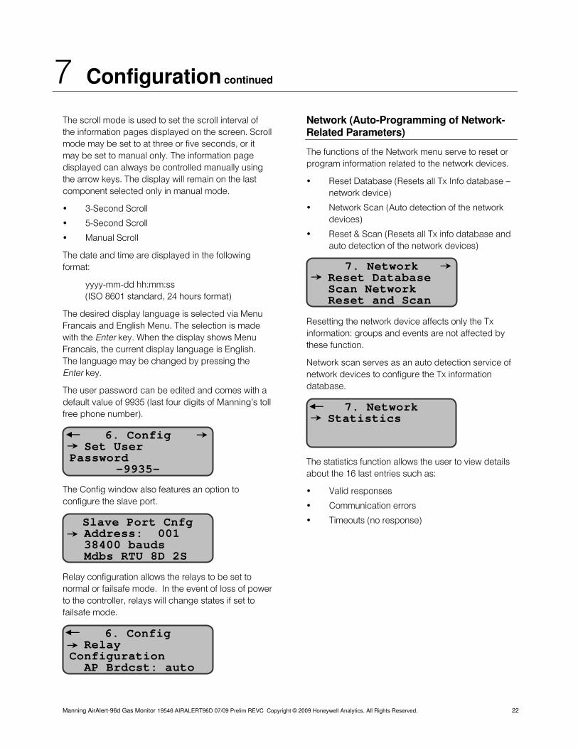
The scroll mode is used to set the scroll interval of the information pages displayed on the screen. Scroll mode may be set to at three or five seconds, or it may be set to manual only. The information page displayed can always be controlled manually using the arrow keys. The display will remain on the last component selected only in manual mode.
• 3-Second Scroll
• 5-Second Scroll
• Manual Scroll
The date and time are displayed in the following format:
yyyy-mm-dd hh:mm:ss (ISO 8601 standard, 24 hours format)
The desired display language is selected via Menu Francais and English Menu. The selection is made with the Enter key. When the display shows Menu Francais, the current display language is English. The language may be changed by pressing the Enter key.
The user password can be edited and comes with a default value of 9935 (last four digits of Manning’s toll free phone number).
The Config window also features an option to configure the slave port.
Relay configuration allows the relays to be set to normal or failsafe mode. In the event of loss of power to the controller, relays will change states if set to failsafe mode.
Network (Auto-Programming of Network-Related Parameters)
The functions of the Network menu serve to reset or program information related to the network devices.
• Reset Database (Resets all Tx Info database — network device)
• Network Scan (Auto detection of the network devices)
• Reset & Scan (Resets all Tx info database and auto detection of the network devices)
7. Network e Reset Databas
o Scan Netw rk Reset and Scan
Resetting the network device affects only the Tx information: groups and events are not affected by these function.
Network scan serves as an auto detection service of network devices to configure the Tx information database.
7. Networatistics
k St 6. Conf
Set User Passwor
ig
d -9935-
The statistics function allows the user to view details about the 16 last entries such as:
• Valid responses
• Communication errors
• Timeouts (no response) Slave Port Cnfg1
Address: 00 38400 bauds
Mdbs RTU 8D 2S
6. C Relay Co i
onfig
nf guration AP Brdcst: auto
Manning AirAlert-96d Gas Monitor 19546 AIRALERT96D 07/09 Prelim REVC Copyright © 2009 Honeywell Analytics. All Rights Reserved. 22
7 Configuration continued
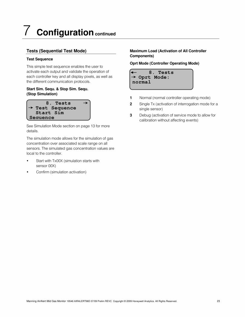
Tests (Sequential Test Mode)
Test Sequence
This simple test sequence enables the user to activate each output and validate the operation of each controller key and all display pixels, as well as the different communication protocols.
Start Sim. Sequ. & Stop Sim. Sequ. (Stop Simulation)
See Simulation Mode section on page 13 for more details.
The simulation mode allows for the simulation of gas concentration over associated scale range on all sensors. The simulated gas concentration values are local to the controller.
• Start with Tx00X (simulation starts with sensor 00X)
Maximum Load (Activation of All Controller Components)
Oprt Mode (Controller Operating Mode)
8. Tests Oprt Mode: normal
1 Normal (normal controller operating mode) 8. Tests
ce Test Sequen Start Sim Sequence
2 Single Tx (activation of interrogation mode for a single sensor)
3 Debug (activation of service mode to allow for calibration without affecting events)
• Confirm (simulation activation)
Manning AirAlert-96d Gas Monitor 19546 AIRALERT96D 07/09 Prelim REVC Copyright © 2009 Honeywell Analytics. All Rights Reserved. 23
8 Specifications
Power Requirements: 24 Vdc, 500 mA
Operating Environment: Ordinary location
Operating Temperature Range: —4°F to 122°F (—20°C to 50°C)
Operating Humidity Range: 0 to 95% RH, (non condensing)
Operating Altitude: Up to 9843 ft. (3,000 m)
Network Capacity:
Up to 96 sensors, 32 per channel
Channel 1, 2, and 3: MODBUS
Channel 4: Modbus output to PLC
Communication (length of lines):
Up to 2,000 feet (600 m) per channel 24 AWG #9841 Belden Cable
T-tap: 65 feet (20 m) maximum per t-tap,130 feet (40 m) total
User Interface:
Graphic 122 x 82 dot matrix backlit display
User friendly keypad
Visual Indicators:
Power On Green LED
Warn Red LED (blinking upon an event)
Alarm Red LED
High Alarm Red LED
Fault Yellow LED
Tx Amber LED (blink when used)
Rx Green LED (blink when used)
Outputs:
4 DPDT relays
5A, 30 Vdc or 250 Vac (resistive load)
Time Delays: 0, 30, and 45 seconds, and1 to 99 minutes before and after alarm
Battery: Lithium battery, 3 volts
Enclosure: NEMA 4x, cast aluminium #A356.0T6
Overvoltage Category: II
Dimensions: 9.50” (W) x 14.00” (H) x 3.50” (D)
Weight: 11.4 lbs (5.2 kg)
9 Maintenance
The Manning AirAlertTM96d is a maintenance free controller. Only the sensors need periodic inspection and calibration (see sensor manual).
Periodic Inspections and Calibration
Honeywell Analytics provides its customers with specialized gas detection equipment. Beyond the warranty period, the systems must be maintained and calibrated on a regular basis (normally two times a year).
Honeywell Analytics will not assume responsibility for the interruption of service or malfunctioning of its equipment as a result of the discontinuance of maintenance and calibration services.
If unit span or zero cannot be adjusted, the sensor may be approaching its end-of-life and must be replaced. Keep an operation log of all maintenance, calibrations and alarm events.
Replacement Parts
A replacement 3V lithium battery is also available. If the memory card option is present, spare SDcards are also available.
Due to continuous evolution of our products, please contact our service department for ordering parts or for more details.
Cleaning
Clean the exterior with a soft, damp cloth. Do not use solvents, soaps or polishers.
Battery Disposal
This instrument contains a lithium battery. Do not mix with the solid waste stream. Spent batteries should be disposed of by a qualified recycler or hazardous materials handler.
Manning AirAlert-96d Gas Monitor 19546 AIRALERT96D 07/09 Prelim REVC Copyright © 2009 Honeywell Analytics. All Rights Reserved. 24
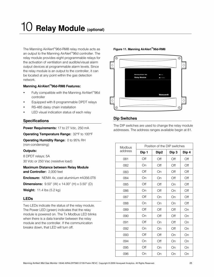
10 Relay Module (optional)
The Manning AirAlertTM96d-RM8 relay module acts as an output to the Manning AirAlertTM96d controller. The relay module provides eight programmable relays for the activation of ventilation and audible/visual alarm output devices at programmable alarm levels. Since the relay module is an output to the controller, it can be located at any point within the gas detection network.
Manning AirAlertTM96d-RM8 Features:
• Fully compatible with the Manning AirAlertTM96d controller
• Equipped with 8 programmable DPDT relays
• RS-485 daisy chain installation
• LED visual indication status of each relay
Specifications
Power Requirements: 17 to 27 Vdc, 250 mA
Operating Temperature Range: 32°F to 100°F
Operating Humidity Range: 0 to 95% RH (non-condensing)
Outputs:
8 DPDT relays; 5A
30 Vdc or 250 Vac (resistive load)
Maximum Distance between Relay Module and Controller: 2,000 feet
Enclosure: NEMA 4x, cast aluminium #A356.0T6
Dimensions: 9.50” (W) x 14.00” (H) x 3.50” (D)
Weight: 11.4 lbs (5.2 kg)
LEDs
Two LEDs indicate the status of the relay module. The Power LED (green) indicates that the relay module is powered on. The Tx Modbus LED blinks when there is a data transfer between the relay module and the controller. If the communication breaks down, that LED will turn off.
Figure 11. Manning AirAlertTM96d-RM8
Power
TX ModBus
Manning AirAlert 96d
Relay Module
Dip Switches
The DIP switches are used to change the relay module addresses. The address ranges available begin at 81.
Modbus address
Position of the DIP switches
Dip 1 Dip2 Dip 3 Dip 4
081 Off Off Off Off
082 On Off Off Off
083 Off On Off Off
084 On On Off Off
085 Off Off On Off
086 On Off On Off
087 Off On On Off
088 On On On Off
089 Off Off Off On
090 On Off Off On
091 Off On Off On
092 On On Off On
093 Off Off On On
094 On Off On On
095 Off On On On
096 On On On On
Manning AirAlert-96d Gas Monitor 19546 AIRALERT96D 07/09 Prelim REVC Copyright © 2009 Honeywell Analytics. All Rights Reserved. 25
10 Relay Module (optional) continued
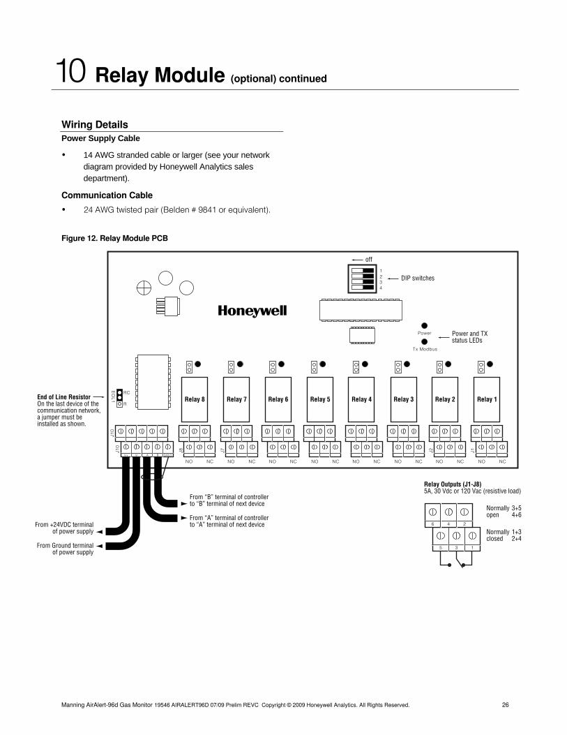
Wiring Details Power Supply Cable
• 14 AWG stranded cable or larger (see your network diagram provided by Honeywell Analytics sales department).
Communication Cable
• 24 AWG twisted pair (Belden # 9841 or equivalent).
Figure 12. Relay Module PCB
Power
Tx Modbus
Normallyopen
Normallyclosed
3+54+6
1+32+4
6 4 2
5 3 1
RC
R
EO
L1
Relay Outputs (J1-J8) 5A, 30 Vdc or 120 Vac (resistive load)
V+ V- SHLDA B
J10
J10
J8 J7 J2 J1
From “B” terminal of controllerto “B” terminal of next device
From “A” terminal of controllerto “A” terminal of next deviceFrom +24VDC terminal
of power supply
From Ground terminalof power supply
NO NCNO NC
Relay 2
NO NC
Relay 3 Relay 1
NO NC
Relay 4
NO NCNO NC
Relay 6
NO NC
Relay 7 Relay 5
NO NC
Relay 8End of Line Resistor On the last device of thecommunication network,a jumper must be installed as shown.
Power and TXstatus LEDs
1234
off
DIP switches
Manning AirAlert-96d Gas Monitor 19546 AIRALERT96D 07/09 Prelim REVC Copyright © 2009 Honeywell Analytics. All Rights Reserved. 26
Manning AirAlert-96d Gas Monitor 19546 AIRALERT96D 07/09 Prelim REVC Copyright © 2009 Honeywell Analytics. All Rights Reserved. 27
11 Limited Warranty
1. Limited Warranty Honeywell Analytics, Inc. warrants to the original purchaser and/or ultimate customer (“Purchaser”) of Manning products (“Product”) that if any part thereof proves to be defective in material or workmanship within eighteen (18) months of the date of shipment by Honeywell Analytics or twelve (12) months from the date of first use by the purchaser, whichever comes first, such defective part will be repaired or replaced, free of charge, at Honeywell Analytics’ discretion if shipped prepaid to Honeywell Analytics at 405 Barclay Blvd., Lincolnshire, IL 60069, in a package equal to or in the original container. The Product will be returned freight prepaid and repaired or replaced if it is determined by Honeywell Analytics that the part failed due to defective materials or workmanship. The repair or replacement of any such defective part shall be Honeywell Analytics’ sole and exclusive responsibility and liability under this limited warranty.
2. Exclusions
A. If gas sensors are part of the Product, the gas sensor is covered by a twelve (12) month limited warranty of the manufacturer.
B. If gas sensors are covered by this limited warranty, the gas sensor is subject to inspection by Honeywell Analytics for extended exposure to excessive gas con-centrations if a claim by the Purchaser is made under this limited warranty. Should such inspection indicate that the gas sensor has been expended rather than failed prematurely, this limited warranty shall not apply to the Product.
C. This limited warranty does not cover consum-able items, such as batteries, or items subject to wear or periodic replacement, including lamps, fuses, valves, vanes, sensor elements, cartridges, or filter elements.
3. Warranty Limitation and Exclusion Honeywell Analytics will have no further obligation under this limited warranty. All warranty obligations of Honeywell Analytics are extinguishable if the Product has been subject to abuse, misuse, negligence, or accident or if the Purchaser fails to perform any of the duties set forth in this limited warranty or if the Product has not been operated in accordance with instructions, or if the Product serial number has been removed or altered.
4. Disclaimer of Unstated Warranties THE WARRANTY PRINTED ABOVE IS THE ONLY WARRANTY APPLICABLE TO THIS PURCHASE. ALL OTHER WARRANTIES, EXPRESS OR IMPLIED, INCLUDING, BUT NOT LIMITED TO, THE IMPLIED WARRANTIES OF MERCHANTABILITY OR FITNESS FOR A PARTICULAR PURPOSE ARE HEREBY DISCLAIMED.
5. Limitation of Liability
IT IS UNDERSTOOD AND AGREED THAT HONEYWELL ANALYTIC’S LIABILITY, WHETHER IN CONTRACT, IN TORT, UNDER ANY WARRANTY, IN NEGLIGENCE OR OTHERWISE SHALL NOT EXCEED THE AMOUNT OF THE PURCHASE PRICE PAID BY THE PURCHASER FOR THE PRODUCT AND UNDER NO CIRCUMSTANCES SHALL HONEYWELL ANALYTICS BE LIABLE FOR SPECIAL, INDIRECT, OR CONSEQUENTIAL DAMAGES. THE PRICE STATED FOR THE PRODUCT IS A CONSIDERA-TION LIMITING HONEYWELL ANALYTICS’ LIABILITY. NO ACTION, REGARDLESS OF FORM, ARISING OUT OF THE TRANSACTIONS UNDER THIS WARRANTY MAY BE BROUGHT BY THE PURCHASER MORE THAN ONE YEAR AFTER THE CAUSE OF ACTIONS HAS OCCURRED.