Embed Size (px)
Citation preview
Multi-beamforming for 3D ultrasonic imaging J. Brizuela*1, J. Camacho*2, L. Medina*2, J. F. Cruza*2
*Ultrasound for Medical and Industrial Applications Group (UMEDIA) 1National Scientific and Technical Research Council (CONICET - CNEA), San Martín, 1650 Buenos Aires, Argentina.
2Spanish National Research Council (CSIC), La Poveda (Arganda del Rey), 28500 Madrid, Spain.
Abstract – This work describes the development of a new 3D ultrasonic imaging method that combines different beamforming techniques (Phased Array -PA- and Synthetic Aperture Focusing Technique -SAFT-). The proposed methodology uses a silicone mask along the x-axis to produce a wide beam in the array width direction (y-axis). Then, a coherent-spatial composition of several phased array B-scan images is implemented to get the voxels. Three-dimensional (3D) reconstruction is performed by SAFT techniques along the y-axis, taking advantage of the broad beam produced by the mask and of the spatial position of samples on each B-mode image. This approach simplifies both, the hardware and the algorithms required for 3D reconstruction, giving a quantitative high quality volumetric image in nearly real time. The performance of this technique was analyzed using a simple needle phantom and an aluminum block with holes. Both inspections were done in a degassed water bath.
Keywords – Beamforming, 3D images, NDT, SAFT, Phased Array.
I. INTRODUCTION
The use of ultrasound phased array techniques in NDT is widely used due to the increase in scanning speed and the advantages of electronic focusing and steering. However, while a 1D phased array provides good resolution in the x-direction, it is limited in the y-direction due to the large element width. A method to overcome this drawback would be using 2D arrays to improve resolution in this direction as well. A 2D phased array probe can provide 3D images with good spatial resolution [1]. However, this results in increased complexity and cost of the electronics.
Another approach is the synthetic aperture focusing technique (SAFT), which provides good resolution [2]. This technique requires that every array element produce a 3D omnidirectional beam so that signals can be 3D combined. The element size must be small, which deteriorates the SNR of the acquired data. Furthermore, ideally, a full dataset with all the possible combinations of emitters and receivers must be acquired and processed, which involves a large amount of data and computing time, especially for volumetric imaging.
The method proposed in this work is based on a combination of two conventional imaging techniques: Phased array imaging in the x-direction and SAFT. The former provides a set of linear or sectorial B-mode images, which are well focused in the x-z plane and poorly in the y-direction. A set of these images is combined by synthetic aperture focusing in the y-direction. To this purpose, nearly omnidirectional beams are generated using conventional arrays and a silicone mask. The 3D volume image is
progressively built at a high frame rate, taking advantage the low-cost computing power of the processors used for beamforming.
II. BEAM GENERATION
The proposed methodology uses conventional 1D array probes aligned with the x-axis, with mechanical scanning in the y-direction to minimize hardware requirements. A V-shaped silicone mask (lens) is mounted in front of the probe. The mask (lens) has a thin slot that reduces the active area of the elements in the y-direction to produce a wide beam (Fig. 1a).
Silicone is a low-cost material that can be easily shaped. Furthermore, it presents high acoustical attenuation (14.0 dB cm-1) and low velocity of sound (cS ≈ 1.03 mm us-1), as compared to that of water (cW ≈ 1.48 mm us-1) [3]. These properties are suitable to emulate a narrow width phased array probe by leaving a thin strip without silicone on the sensor surface that makes the ultrasonic beam to spread out (Fig. 1b). The half-angle that defines the main-lobe width according to the Rayleigh criterion is:
∆ = ( / ) (1)
For a 5 MHz transducer in water immersion and a slot width S of 1.5 mm, the wavelength is λ ≈ 0.3 mm and Δα ≈ 12º. On the other hand, the mask sidewalls have been designed to get total internal reflection into the silicone, following the Snell’s law:
= ≥ 44° (2)
The lens was done filling a mould with silicone (Silastic 3481 - Feroca Composites, Spain) of two components: a base gel and a catalyst, which were mixed into a 100:5 ratio of mass respectively. The polymer was allowed to stand approx. 24 hrs for curing. The small air bubbles, which get formed into the polymer during its preparation, were kept to produce inner scatters that reduce the wave propagation inside the mask.
III. 3D IMAGE RECONSTRUCTION PROCEDURE
The 3D generation process consists on acquiring linear or sector-scans (B-mode images in the xz-plane) of the volume-of-interest (VOI) with the phased array probe, while the probe is mechanically moved along the y-direction. The VOI is spatially sampled keeping a distance between B-mode images no greater than λ/2 to avoid grating lobes [4].
Each linear or sector-scan image is well focused (dynamic focusing) in the xz-plane and represents a thick pie-shaped slice of the VOI. The broad beam generated in the y-direction introduces on the B-mode images the scattering information that belongs to adjacent regions.
Linear scans without steering are saved in a rectangular image format. Each B-mode image contains L = N-A+1 lines (A-scans) of K samples, where N means the element number of the PA probe and A is the active subaperture defined for emitting and receiving the ultrasonic beam. The electronic scan allows a field of view of width d.L, being d the centre-to-centre inter-element spacing value (pitch).
Each 2D high-resolution image (composed slice on the xz-plane) is obtained by the synthetic aperture imaging technique (SAFT) using a monostatic approach that offers a fast numerical reconstruction [5-6]. Each VOI slice consists in a set of L lines and K samples obtained from a buffer of M B-mode images, keeping their relative spatial position.
The VOI slice is formed line-by-line, extracting from the M A-scans that belong to the same yz-plane, the information corresponding to every voxel. Each voxel is obtained from a set of samples that are chosen by considering the round trip time-of-flight from each 2D image point (focus) to each B-mode array position in the set of the M images. The obtained
2D image is a coherent sum of M B-mode images. It is focused at all depths in the yz-plane, as well as in the xz plane, the latter due to the phased array technique.
The lateral resolution in the yz-plane is improved by increasing the number M of B-mode images that are used to get a single 2D image [7]. On the other hand, the lateral resolution in the xz-plane is determined by the active aperture size used in the phased array system, using dynamic focusing.
Finally, the M value chosen for processing determines the maximum number of 2D images used for the VOI reconstruction, Thus, for a mechanical scanning of P B-mode acquired images, the VOI generated will have I = P-M+1 high-resolution 2D images.
IV. RESULTS
Following the arrangement shown in Fig. 1a, a 5 MHz phased array transducer of 128 elements for immersion (Imasonic, France) with d = 0.5 mm pitch, and a SITAU-111 phased array system (DASEL Sistemas, Spain) were used for testing the mask beam pattern and the beamforming procedure. In all the experimental cases, the RF signals were acquired with a sampling rate of 40 MHz. The acquired B-mode images were buffered and then composed using a parallel computing language (OpenCL) on a simple CPU platform (Intel Core i7 processor @ 2.7GHz).
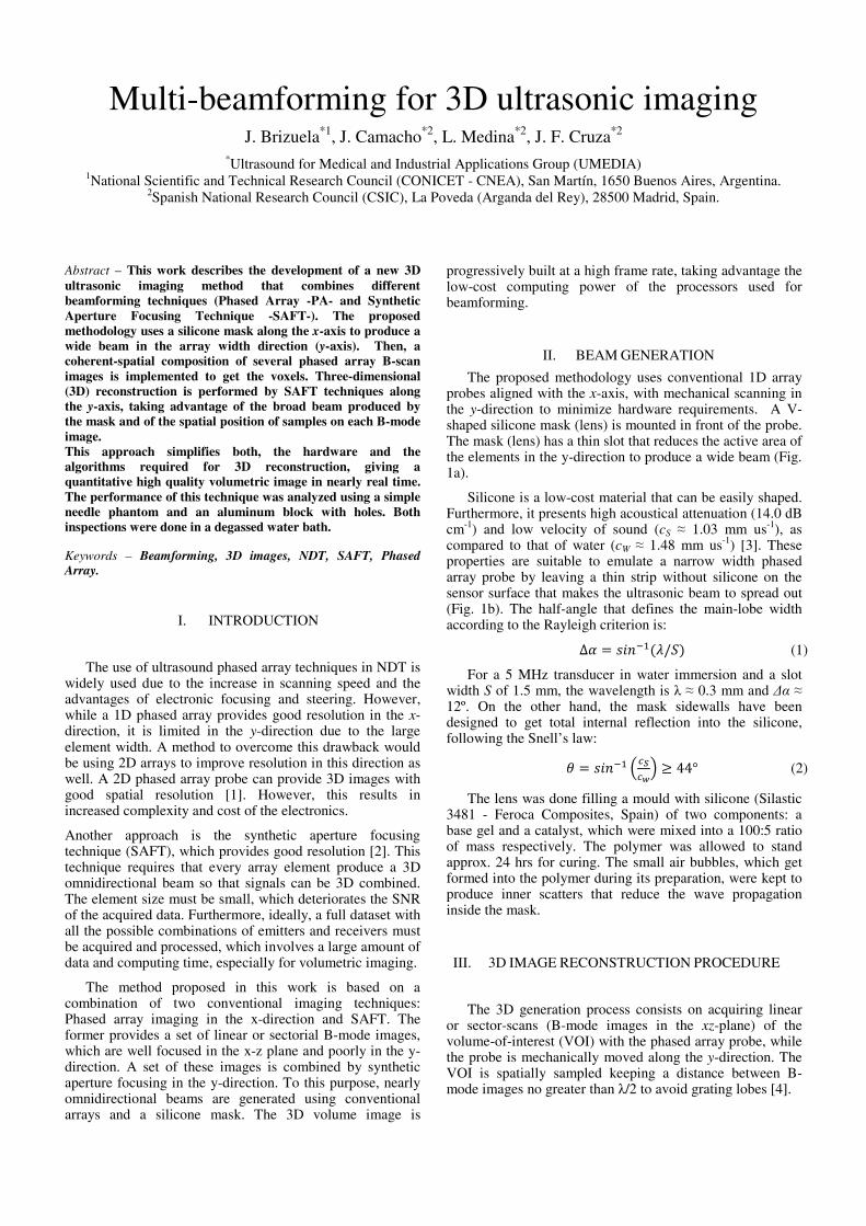
First, a single pin header located in degassed water at 50 mm from the transducer was used as a point reflector. The transducer subaperture size was set to 16 mm (A = 32 elements). The spatial sampling distance of the VOI was set to 0.1 mm, which is represents λ/3 for the transducer’s center frequency in water. The scanned VOI is 50x70x35 mm (x,y,z), which corresponds to 97x700x1860 voxels.
The C-scan image of the VOI shown in Fig. 2a has been obtained using the phased array probe without mask, which shows a poor resolution in the y-direction. The point-spread function (PSF) shows a wide beam on the yz-plane (Fig. 2e). Hence, the length of the point-like reflector along the y-axis is 10 mm at 6 dB, which matches well with the transducer width. Since a substantially plane wave is generated in the y-direction, no image composition is possible.
A new C-scan image for the VOI is taken using the silicone mask (Fig. 2b). The broad beam emitted in the yz-plane makes the reflector size be even more lengthened. On the resultant PSF function (Fig. 2e), a half-angle of 11.3º for the beam opening can be determined at 20 dB, which is a value not far away from the expected one (12º). The mask effect can be seen as the diffraction of a small-size transducer emitting spherical waves on the yz-plane over some angle range. The lateral view of Fig. 2c shows the loss of spatial resolution introduced by the broad beam.
Finally, a C-scan using the coherent composition of M = 161 B-mode images (16 mm of aperture, the same as used for the phased array system to keep equal resolution in x and y) for beamforming a 2D-image is shown in Fig. 2d. The resolution in the y-direction is highly improved and the side-lobes are reduced below 30 dB.
b)-
Reflector (pin-head)
Rubber support
Mechanical scan direction
Degassed water
Silicone lens
x
y
z
Electronic scan direction
Phased array transducer (5 Mhz – 128 eltms)
Broad beam
a)-
8
2
PA transducer
40
20
θ=45º
Silicone lens profile (with random air bubbles)
S = 1.5
Figure 1. a)- Measurement setup for testing the multi-beamforming approach. A single pin head in degassed water is used as target. b)- Silicone lens profile used to get a thinner PA probe and produce a broad beam (units in mm).
Taking into account the resultant PSF function the reflector size has a length of 1 mm at 6 dB (Fig. 2e). The same procedure was repeated using half the aperture (M = 81 B-mode images). The lateral resolution is also improved and remains very close to the previous case until 20 dB, where the side-lobes begin to rise.
The achieved performance is six 2D images per second. This frame rate includes data upload to memory, processing and data saving. It is important to take into account that acquisitions in water contain more samples per image, which is a worst-case scenario for NDT inspections.
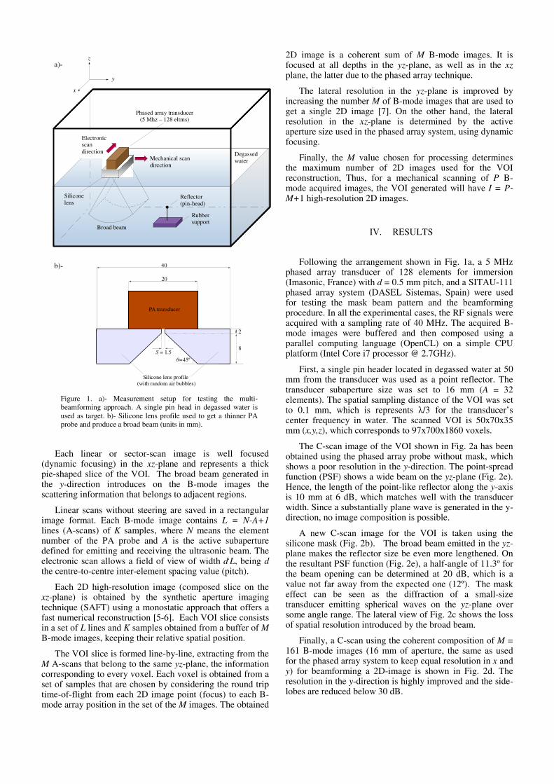
Another experiment was carried out using an aluminium block with a conical tip drill (Fig. 3a). The inspection was also done by immersion with a water path of 56 mm. The B-mode images were taken with 0.5 mm of resolution (> λ/2 in Al) using the same phased array probe and system, but with 32 mm of active subaperture (64 elements) focused at 20 mm of depth. The VOI has 35x40x80 mm (x,y,z), which is represented in 65x160x582 voxels.
As in the previous case, the hole-tip size appears lengthened in the C-scan image obtained with the mask. Furthermore, the beam inside the block-test gets broader due to the refraction at the interface water-aluminium. Since the sound velocity in the second media (6.2 mm us-1) is higher than the first (1.48 mm us-1) the half-angle of aperture is 38º at 20 dB (see PSF function on Fig. 3b), which corresponds to an incident beam angle of 11º.
The image reconstruction was carried out with an aperture size of 32 mm (M = 65 B-mode images), which is the beam width measured at 20 dB on its PSF function. For beamforming, focal laws for each 2D-image point were computed taking into account the round-trip time-of-flight of the sound path from each B-mode scan position, trough the interface water-aluminium up to every focus in the image. There are several approaches to compute the delay laws required for beamforming when there are interfaces on the sound path, such as [8].
The resultant C-scan image is shown in Fig. 3d, where can be seen that the resolution achieved along the y-axis is improved. On the obtained PSF function the side-lobes are reduced up to 22 dB and the hole-tip length can be measured at 6 dB as 1 mm (Fig. 3b)
The 2D-images are composed at 190 frames per second (rate of upload, process and save data to disk). The beamforming performance is improved because the B-mode images contain fewer samples per A-scan than in the previous case. This rate allows displaying some composed 2D-image while the inspection is carried out and represents the VOI after the inspection is finished, using 3D CAD software.
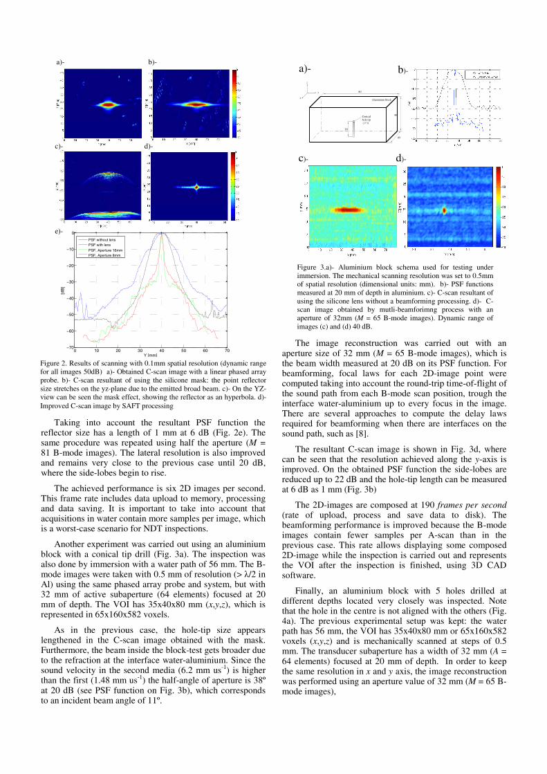
Finally, an aluminium block with 5 holes drilled at different depths located very closely was inspected. Note that the hole in the centre is not aligned with the others (Fig. 4a). The previous experimental setup was kept: the water path has 56 mm, the VOI has 35x40x80 mm or 65x160x582 voxels (x,y,z) and is mechanically scanned at steps of 0.5 mm. The transducer subaperture has a width of 32 mm (A = 64 elements) focused at 20 mm of depth. In order to keep the same resolution in x and y axis, the image reconstruction was performed using an aperture value of 32 mm (M = 65 B-mode images),
0 10 20 30 40 50 60 70−70
−60
−50
−40
−30
−20
−10
0
Y [mm]
[dB
]
PSF without lensPSF with lens
PSF, Aperture 16mmPSF, Aperture 8mm
a)-
d)-
e)-
b)-
c)-
Figure 2. Results of scanning with 0.1mm spatial resolution (dynamic rangefor all images 50dB) a)- Obtained C-scan image with a linear phased arrayprobe. b)- C-scan resultant of using the silicone mask: the point reflectorsize stretches on the yz-plane due to the emitted broad beam. c)- On the YZ-view can be seen the mask effect, showing the reflector as an hyperbola. d)-Improved C-scan image by SAFT processing
Aluminium block
40
40
80
x
y
z
Conical hole tip
20
( 1)
a)- b)-
c)- d)-
Figure 3.a)- Aluminium block schema used for testing under immersion. The mechanical scanning resolution was set to 0.5mm of spatial resolution (dimensional units: mm). b)- PSF functions measured at 20 mm of depth in aluminium. c)- C-scan resultant of using the silicone lens without a beamforming processing. d)- C-scan image obtained by mutli-beamforimng process with an aperture of 32mm (M = 65 B-mode images). Dynamic range of images (c) and (d) 40 dB.
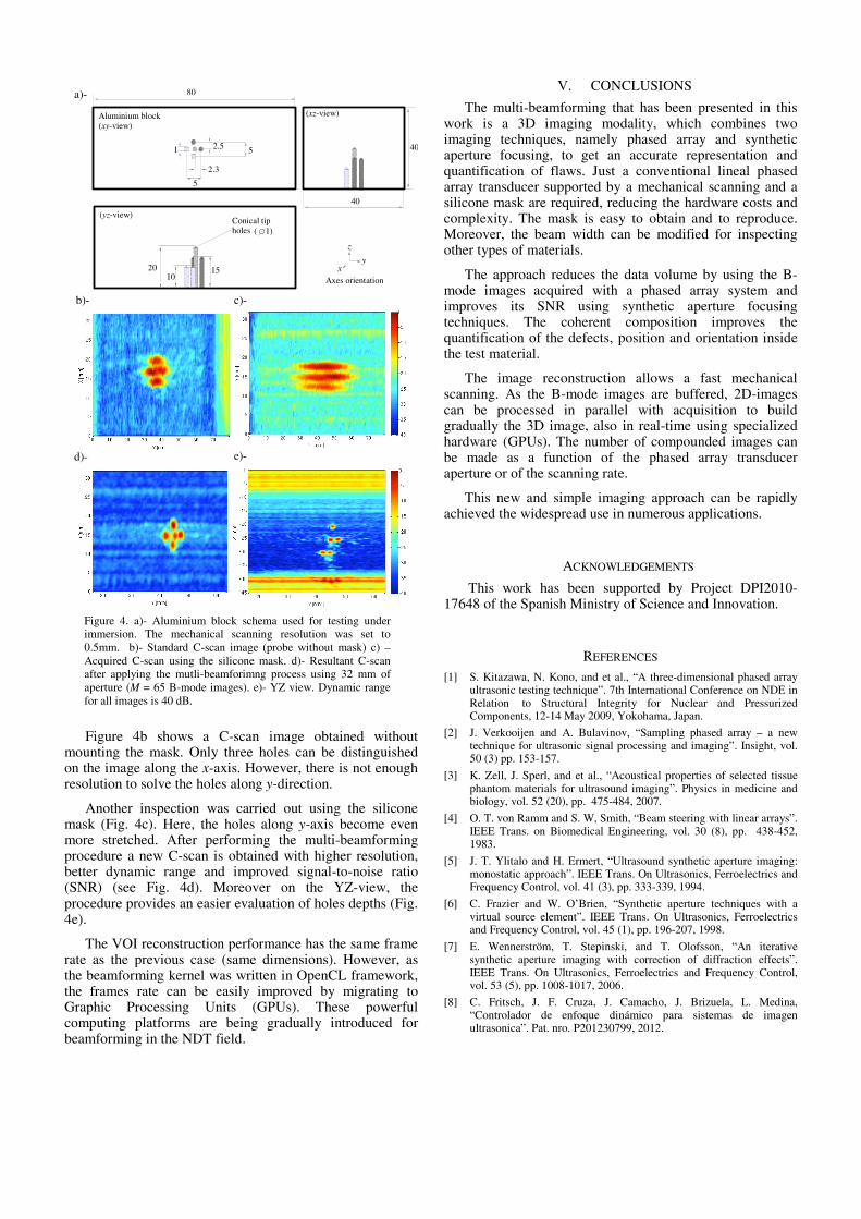
Figure 4b shows a C-scan image obtained without mounting the mask. Only three holes can be distinguished on the image along the x-axis. However, there is not enough resolution to solve the holes along y-direction.
Another inspection was carried out using the silicone mask (Fig. 4c). Here, the holes along y-axis become even more stretched. After performing the multi-beamforming procedure a new C-scan is obtained with higher resolution, better dynamic range and improved signal-to-noise ratio (SNR) (see Fig. 4d). Moreover on the YZ-view, the procedure provides an easier evaluation of holes depths (Fig. 4e).
The VOI reconstruction performance has the same frame rate as the previous case (same dimensions). However, as the beamforming kernel was written in OpenCL framework, the frames rate can be easily improved by migrating to Graphic Processing Units (GPUs). These powerful computing platforms are being gradually introduced for beamforming in the NDT field.
V. CONCLUSIONS
The multi-beamforming that has been presented in this work is a 3D imaging modality, which combines two imaging techniques, namely phased array and synthetic aperture focusing, to get an accurate representation and quantification of flaws. Just a conventional lineal phased array transducer supported by a mechanical scanning and a silicone mask are required, reducing the hardware costs and complexity. The mask is easy to obtain and to reproduce. Moreover, the beam width can be modified for inspecting other types of materials.
The approach reduces the data volume by using the B-mode images acquired with a phased array system and improves its SNR using synthetic aperture focusing techniques. The coherent composition improves the quantification of the defects, position and orientation inside the test material.
The image reconstruction allows a fast mechanical scanning. As the B-mode images are buffered, 2D-images can be processed in parallel with acquisition to build gradually the 3D image, also in real-time using specialized hardware (GPUs). The number of compounded images can be made as a function of the phased array transducer aperture or of the scanning rate.
This new and simple imaging approach can be rapidly achieved the widespread use in numerous applications.
ACKNOWLEDGEMENTS
This work has been supported by Project DPI2010-17648 of the Spanish Ministry of Science and Innovation.
REFERENCES [1] S. Kitazawa, N. Kono, and et al., “A three-dimensional phased array
ultrasonic testing technique”. 7th International Conference on NDE in Relation to Structural Integrity for Nuclear and Pressurized Components, 12-14 May 2009, Yokohama, Japan.
[2] J. Verkooijen and A. Bulavinov, “Sampling phased array – a new technique for ultrasonic signal processing and imaging”. Insight, vol. 50 (3) pp. 153-157.
[3] K. Zell, J. Sperl, and et al., “Acoustical properties of selected tissue phantom materials for ultrasound imaging”. Physics in medicine and biology, vol. 52 (20), pp. 475-484, 2007.
[4] O. T. von Ramm and S. W, Smith, “Beam steering with linear arrays”. IEEE Trans. on Biomedical Engineering, vol. 30 (8), pp. 438-452, 1983.
[5] J. T. Ylitalo and H. Ermert, “Ultrasound synthetic aperture imaging: monostatic approach”. IEEE Trans. On Ultrasonics, Ferroelectrics and Frequency Control, vol. 41 (3), pp. 333-339, 1994.
[6] C. Frazier and W. O’Brien, “Synthetic aperture techniques with a virtual source element”. IEEE Trans. On Ultrasonics, Ferroelectrics and Frequency Control, vol. 45 (1), pp. 196-207, 1998.
[7] E. Wennerström, T. Stepinski, and T. Olofsson, “An iterative synthetic aperture imaging with correction of diffraction effects”. IEEE Trans. On Ultrasonics, Ferroelectrics and Frequency Control, vol. 53 (5), pp. 1008-1017, 2006.
[8] C. Fritsch, J. F. Cruza, J. Camacho, J. Brizuela, L. Medina, “Controlador de enfoque dinámico para sistemas de imagen ultrasonica”. Pat. nro. P201230799, 2012.
xy
z
(yz-view)Conical tip holes
20
( 1)
1510 Axes orientation
40
2.5 5
2.3
5
40
80
1
Aluminium block(xy-view)
(xz-view)
a)-
c)- b)-
e)- d)-
Figure 4. a)- Aluminium block schema used for testing under immersion. The mechanical scanning resolution was set to 0.5mm. b)- Standard C-scan image (probe without mask) c) – Acquired C-scan using the silicone mask. d)- Resultant C-scan after applying the mutli-beamforimng process using 32 mm of aperture (M = 65 B-mode images). e)- YZ view. Dynamic range for all images is 40 dB.