Embed Size (px)
Citation preview

Multi-Amp Configuration Guide Step-by-Step Guide to Multi-Amp Systems
using AE Techron 2100 and 7000-Series Amplifiers
574.295.9495 | www.aetechron.com 2507 Warren Street, Elkhart, IN 46516

AE TECHRON MULTI-AMP CONFIGURATION GUIDE
2 Information subject to change 97-8002465_04-04-19
1 Multi-Amp Systems Using 2100 or 7000 Series Amplifiers ....................................................................... 4 1.1 Safety First ....................................................................................................................................................... 4 1.2 Overview ........................................................................................................................................................... 4 1.3 Multi-Amp Configuration Accessories ............................................................................................................. 4 1.4 Accessory Recommendations by System Type .............................................................................................. 5 2 Multi-amp System Principles ..................................................................................................................... 6 2.1 One Master Amplifier for Series Systems ....................................................................................................... 6 2.2 All Master Amplifiers for Parallel Systems ...................................................................................................... 6 2.3 Use only 2100 or 7000-Series Amplifiers of the same Model Number ....................................................... 6 2.4 Use Correct Wiring ........................................................................................................................................... 6 2.5 When Constructing Output Wiring, Use These Basic Criteria ........................................................................ 6 2.6 Operate with Safety in Mind ............................................................................................................................ 6 3 Series Systems Configuration and Wiring .................................................................................................. 7 3.1 Choosing Single-Ended or Differential Configuration for Two-amplifier Systems ........................................ 7 3.2 Configure SIM-BNC-OPTOC Input Cards .......................................................................................................... 7 3.3 Install SIM-BNC-OPTOC Input Cards in Amplifiers .......................................................................................... 9 3.4 Configure Amplifiers’ Main Boards for Slave Operation ................................................................................ 9 3.5 Remove Output Terminal Resistor ................................................................................................................ 10 3.6 Attach Master/Slave Labels (optional) ......................................................................................................... 10 3.7 Series System Wiring ..................................................................................................................................... 10 3.8 Two in Series – Differential ........................................................................................................................... 10 3.9 Two or Three in Series – Single Ended ......................................................................................................... 14 4 Parallel Systems Configuration, Wiring and Balancing ........................................................................... 19 4.1 Install Ballast Resistors ................................................................................................................................. 19 4.2 Disable Gain Controls (2105/7212/7224 models only) ............................................................................ 20 4.3 Parallel System Balancing ............................................................................................................................. 20
Table of Contents

AE TECHRON MULTI-AMP CONFIGURATION GUIDE
97-8002465_04-04-19 Information subject to change 3
List of Figures Figure 1.1 – Maximum Continuous Output in 2100 or 7000-Series Multi-amp Systems .................................. 4 Figure 3.1 – Two in Series: Single-Ended vs. Differential....................................................................................... 7 Figure 3.2 – SIM-BNC-OPTOC card jumper locations ............................................................................................. 7 Figure 3.4 – Input Connectors Wiring Diagram ...................................................................................................... 8 Figure 3.3 – Older SIM-BNC-OPTOC card jumper locations ................................................................................... 8 Figure 3.5 – 2105/7212/7224 Amplifier Access Panel Screw Locations .......................................................... 9 Figure 3.6 – Master/Slave Jumper Locations ....................................................................................................... 10 Figure 3.7 – 2105/7212/7224 Output Terminal Resistor ................................................................................. 10 Figure 3.8 – 2110/2120/7548/7796 Output Terminal Resistor ..................................................................... 10 Figure 3.9 – Terminating the Amplifier Input ........................................................................................................ 11 Figure 3.10 – Verifying DC Offset .......................................................................................................................... 11 Figure 3.11 – Verifying Amp Gain .......................................................................................................................... 12 Figure 3.12 – Verifying System Gain ..................................................................................................................... 13 Figure 3.13 – Two Amplifiers in Series – Differential Configuration ................................................................... 14 Figure 3.14 – Terminating the Amplifier Input ...................................................................................................... 15 Figure 3.15 – Verifying DC Offset .......................................................................................................................... 15 Figure 3.16 – Verifying Amp Gain .......................................................................................................................... 16 Figure 3.17 – Verifying System Gain ..................................................................................................................... 17 Figure 3.18 – Two Amplifiers in Series – Single-Ended Configuration ................................................................ 17 Figure 3.19 – Three Amplifiers in Series – Single-Ended Configuration ............................................................. 18 Figure 4.1 – 2105/7224 Ballast Resistor Mounting ........................................................................................... 19 Figure 4.2 – 2120/7796 Ballast Resistor Mounting ........................................................................................... 19 Figure 4.5 – Gain Control Connection on Main Board......................................................................................... 20 Figure 4.3 – 2105/7224 Ballast Resistor Connected to Output Terminal ......................................................... 20 Figure 4.4 – 2120/7796 Ballast Resistors Connected to Output Terminal ....................................................... 20 Figure 4.6 – Gain Control Pin Settings .................................................................................................................. 20 Figure 4.7 – Connecting for Balancing (Four in Parallel shown).......................................................................... 21 Figure 4.8 – Terminating the Amplifier Input ........................................................................................................ 22 Figure 4.9 – Main Board Balancing Control Locations ......................................................................................... 22 Figure 4.10 – Wiring and Test Points for DC Offset .............................................................................................. 23 Figure 4.12 – Optional BNC Parallel Input Wiring (Three in Parallel shown) ..................................................... 23 Figure 4.11 – Wiring the Paralleled Input Wire ..................................................................................................... 23 Figure 4.13– Wiring and Test Points for Amp Gain .............................................................................................. 24 Figure 4.14– Wiring and Test Points for Gain Matching ...................................................................................... 25 Figure 4.16– Three Amplifiers Paralleled .............................................................................................................. 27 Figure 4.15 – Two Amplifiers Paralleled ............................................................................................................... 27 Figure 4.17 – Four Amplifiers Paralleled ............................................................................................................... 28 Figure A-1 – Wire Current-Carrying Capacity Chart ............................................................................................... 29 Figure B-1 – Critical Wire Lengths in Parallel Systems ......................................................................................... 30 Figure C-1 – Output Cables constructed for use in a Two-in-Parallel System .................................................... 31 Figure D-1 – DB-25 Cable Wiring for a Four-in-Parallel System ........................................................................... 31 Figure E-1 – 2105/7212/7224 Access Panel Screw Locations ........................................................................ 31 Figure E-2 – Master/Slave Jumper Locations ....................................................................................................... 31 Figure E-3 – 2105/7212/7224 Output Terminal Resistor ................................................................................. 31 Figure E-4 – 2110/2120/7548/7796 Output Terminal Resistor...................................................................... 31 Figure E-5 – SIM-BNC-OPTOC, Factory Default Settings ....................................................................................... 31 Figure E-6 – SIM-BNC-OPTOC, Factory Default Settings for older input card version ........................................ 31
AE TECHRON MULTI-AMP CONFIGURATION GUIDE
4 Information subject to change 97-8002465_04-04-19
1.1 Safety First Throughout these instructions special emphasis is placed on good safety practices. The WARNING and CAUTION graphics are used to highlight certain topics that require extra precaution.
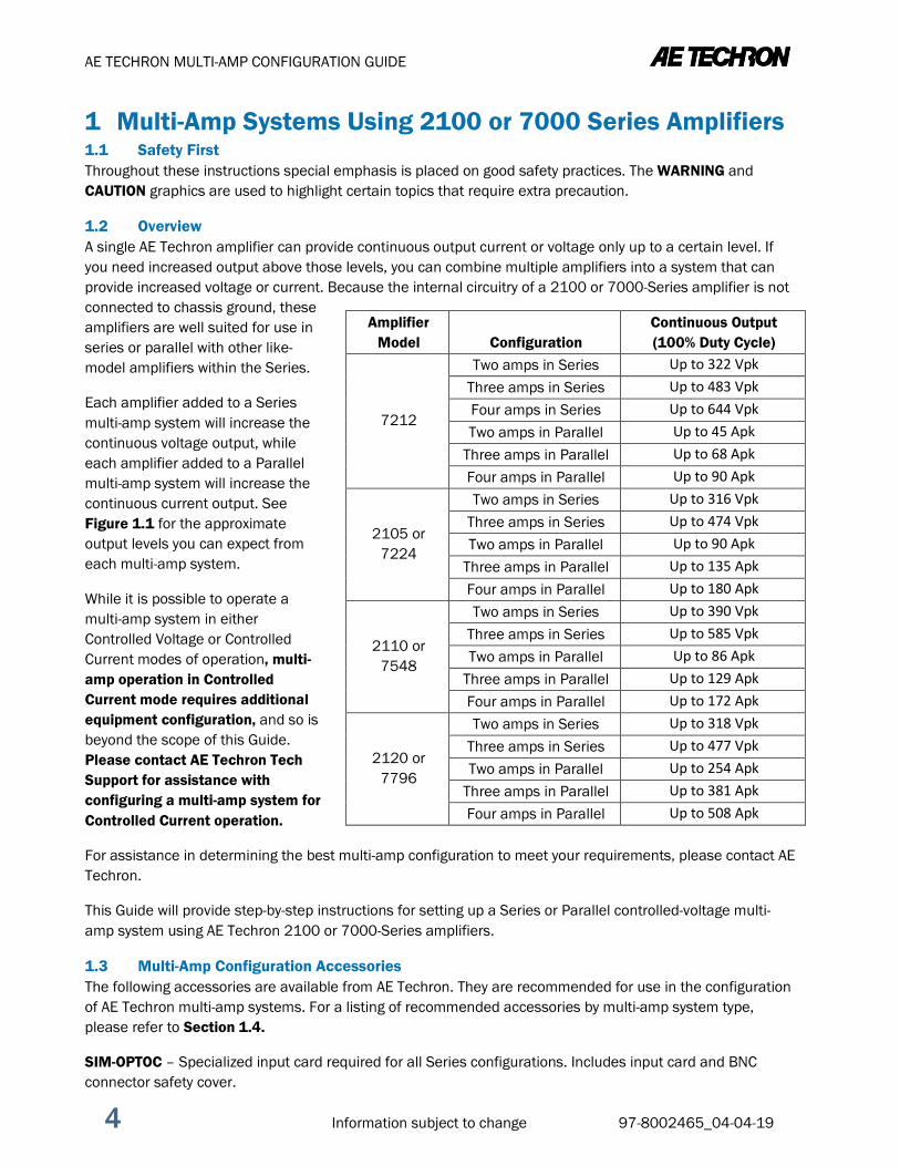
1.2 Overview A single AE Techron amplifier can provide continuous output current or voltage only up to a certain level. If you need increased output above those levels, you can combine multiple amplifiers into a system that can provide increased voltage or current. Because the internal circuitry of a 2100 or 7000-Series amplifier is not connected to chassis ground, these amplifiers are well suited for use in series or parallel with other like-model amplifiers within the Series.
Each amplifier added to a Series multi-amp system will increase the continuous voltage output, while each amplifier added to a Parallel multi-amp system will increase the continuous current output. See Figure 1.1 for the approximate output levels you can expect from each multi-amp system.
While it is possible to operate a multi-amp system in either Controlled Voltage or Controlled Current modes of operation, multi-amp operation in Controlled Current mode requires additional equipment configuration, and so is beyond the scope of this Guide. Please contact AE Techron Tech Support for assistance with configuring a multi-amp system for Controlled Current operation.
For assistance in determining the best multi-amp configuration to meet your requirements, please contact AE Techron.
This Guide will provide step-by-step instructions for setting up a Series or Parallel controlled-voltage multi-amp system using AE Techron 2100 or 7000-Series amplifiers.
1.3 Multi-Amp Configuration Accessories The following accessories are available from AE Techron. They are recommended for use in the configuration of AE Techron multi-amp systems. For a listing of recommended accessories by multi-amp system type, please refer to Section 1.4.
SIM-OPTOC – Specialized input card required for all Series configurations. Includes input card and BNC connector safety cover.
1 Multi-Amp Systems Using 2100 or 7000 Series Amplifiers
Amplifier Model Configuration
Continuous Output (100% Duty Cycle)
7212
Two amps in Series Up to 322 Vpk Three amps in Series Up to 483 Vpk Four amps in Series Up to 644 Vpk Two amps in Parallel Up to 45 Apk
Three amps in Parallel Up to 68 Apk Four amps in Parallel Up to 90 Apk
2105 or 7224
Two amps in Series Up to 316 Vpk Three amps in Series Up to 474 Vpk Two amps in Parallel Up to 90 Apk
Three amps in Parallel Up to 135 Apk Four amps in Parallel Up to 180 Apk
2110 or 7548
Two amps in Series Up to 390 Vpk Three amps in Series Up to 585 Vpk Two amps in Parallel Up to 86 Apk
Three amps in Parallel Up to 129 Apk Four amps in Parallel Up to 172 Apk
2120 or 7796
Two amps in Series Up to 318 Vpk Three amps in Series Up to 477 Vpk Two amps in Parallel Up to 254 Apk
Three amps in Parallel Up to 381 Apk Four amps in Parallel Up to 508 Apk
AE TECHRON MULTI-AMP CONFIGURATION GUIDE
97-8002465_04-04-19 Information subject to change 5
BALLAST RESISTOR KIT (BAL RES KIT) – Three types available: 2105/7212/7224 BAL RES KIT, 2110/7548 BAL RES KIT and 2120/7796 BAL RES KIT. Ballast resistors are required for all Parallel configurations. These ballast resistor kits include one ballast resistor (two in the 2120/7796 kit) with connection terminals and mounting hardware. The2105/7212/7224 BAL RES KIT also contains the shunt required to defeat the amplifier’s external level control.
NOTE: AE Techron Ballast Resistor Kits are sold as parts kits only. Buyers are responsible for installing the Ballast Resistor Kit in a way that meets local Safety requirements.
Alternatively, ballast resistor installation, which will meet generic safety requirements, can be ordered from AE Techron at the time of purchase or is available through AE Techron Service.
DB9M CABLE – High-voltage Interlock cable required for all Series configurations.
PARALLEL WIRING KITS – Six types available: 2105/7212/7224 2-AMP, 2110/2120/7548/7796 2-AMP, 2105/7212/7224 3-AMP, 2110/2120/7548/7796 3-AMP, 2105/7212/7224-AMP, and 2110/2120/7548/7796 4-AMP. Parallel wiring kits include the DB-25 Interlock cable for system communication, and the output wiring for connecting system amplifiers to the load. The kits also include the wire(s) required for wiring the parallel inputs through the Removable Barrier Block (WECO) connectors, BNC patch cable(s) and T-connector(s) for wiring parallel inputs through the BNC input connectors, and the terminated Removable Barrier Block connectors used to terminate the amplifier inputs during system setup. Parallel wiring kits are recommended for all Parallel configurations.
1.4 Accessory Recommendations by System Type
Series Systems
2105, 7212 or 7224 Two in Series: (2) SIM-BNC-OPTOC input cards, (1) DB9M OPTOC cable
2105, 7212 or 7224 Three in Series: (3) SIM-BNC-OPTOC input cards, (2) DB9M OPTOC cables
2110 or 7548 Two in Series: (2) SIM-BNC-OPTOC input cards, (1) DB9M OPTOC cable
2110 or 7548 Three in Series: (3) SIM-BNC-OPTOC input cards, (2) DB9M OPTOC cables
2120 or 7796 Two in Series: (2) SIM-BNC-OPTOC input cards, (1) DB9M OPTOC cable
2120 or 7796 Three in Series: (3) SIM-BNC-OPTOC input cards, (2) DB9M OPTOC cables
Parallel Systems
2105, 7212 or 7224 Two in Parallel: (2) 2105/7212/7224 BAL RES kits, (1) 2105/7212/7224 2-AMP Parallel Wiring kit
2105, 7212 or 7224 Three in Parallel: (3) 2105/7212/7224 BAL RES kits, (1) 2105/7212/7224 3-AMP Parallel Wiring kit
2105, 7212 or 7224 Four in Parallel: (4) 2105/7212/7224 BAL RES kits, (1) 2105/7212/7224 4-AMP Parallel Wiring kit
2110 or 7548 Two in Parallel: (2) 2110/7548 BAL RES kits, (1) 2110/2120/7548/7796 2-AMP Parallel Wiring kit
2110 or 7548 Three in Parallel: (3) 2110/7548 BAL RES kits, (1) 2110/2120/7548/7796 3-AMP Parallel Wiring kit
2110 or 7548 Four in Parallel: (4) 2110/7548 BAL RES kits, (1) 2110/2120/7548/7796 4-AMP Parallel Wiring kit
2120 or 7796 Two in Parallel: (2) 2120/7796 BAL RES kits, (1) 2110/2120/7548/7796 2-AMP Parallel Wiring kit
2120 or 7796 Three in Parallel: (3) 2120/7796 BAL RES kits, (1) 2110/2120/7548/7796 3-AMP Parallel Wiring kit
2120 or 7796 Four in Parallel: (4) 2120/7796 BAL RES kits, (1) 2110/2120/7548/7796 4-AMP Parallel Wiring kit

AE TECHRON MULTI-AMP CONFIGURATION GUIDE
6 Information subject to change 97-8002465_04-04-19
2 Multi-amp System Principles The following configuration and operating principles apply to 2100 or 7000-Series multi-amp systems. Following these basic principles will help to ensure the safety of your equipment and personnel.
2.1 One Master Amplifier for Series Systems Series multi-amp systems are configured with one amplifier configured as the Master amplifier, and all other amplifiers in the system configured as Slave amplifiers. DO NOT operate with more than one Master in your Series multi-amp system.
2.2 All Master Amplifiers for Parallel Systems Parallel multi-amp systems are configured with all amplifiers configured as Master amplifiers. To avoid problems that might occur with signal latency, the input signal is sent through a parallel input cable that delivers the signal simultaneously to all amplifiers in the system.
2.3 Use only 2100 or 7000-Series Amplifiers of the same Model Number Use only AE Techron 2100 or 7000-Series amplifiers of the same model to construct these multiple amplifier systems. You CANNOT combine different models of 2100 or 7000-Series amplifiers in the same system, such as combining 7224 amplifiers with 7548 amplifiers. All amplifiers must be in good working order. Never use other model AE Techron amplifiers or amplifiers made by another manufacturer in a 2100/7000-Series multi-amp system. Such improper connections could damage the amplifiers.
2.4 Use Correct Wiring Never directly connect one amplifier’s OUTPUT terminal (on the output terminal block) to another amplifier’s OUTPUT terminal. The resulting circulating currents will waste power and may damage the amplifiers. Depending on the configuration to be used, the OUTPUT terminal of one amplifier should only be directly connected to the next amplifier’s COM or SAMPLED COMMON terminal, to the load, or to a ballast resistor.
2.5 When Constructing Output Wiring, Use These Basic Criteria In multi-amplifier systems, the quality, gauge, length and rating of the output wiring leading to the load can affect system performance. Wire gauge refers to the diameter of solid wire and is an important factor in the wire’s current-carrying capacity. For Parallel system output wiring, we recommend a wire gauge from 4 AWG (2120/7796 systems) to 10 AWG (2105/7212/7224 systems), and a length of 2.5 to 4 feet. Refer to the Wire Current-Carrying Capacity chart in Appendix A for more information.
Wire length is also an important factor. Particularly in Parallel multi-amp systems, the output wire branches to each amplifier must be carefully matched in length to within ¼-inch to ensure system operation. To assist with output wiring requirements in Parallel systems, AE Techron offers Parallel System Wiring Kits that contain pre-built output wiring. See Section 1.3 for a description of these and other multi-amp accessories. See Appendix B for more information on critical wire lengths in a Parallel system.
Wire rating refers to the allowable voltage handled by the wire. In configuring Series systems for increased voltage, make sure that the wire insulation on output wiring is appropriate for the expected output voltage. Wire length should also be limited to 3 to 4 feet to minimize voltage drop.
2.6 Operate with Safety in Mind Potentially lethal voltages and currents are present within the 2100/7000-Series amplifiers. While the amplifiers’ chassis are earth grounded, all internal grounds are floating. Particularly in systems assembled for increased voltage (Series configurations), all internal grounds of Slave amplifiers could carry lethal voltage levels.
AE TECHRON MULTI-AMP CONFIGURATION GUIDE
97-8002465_04-04-19 Information subject to change 7
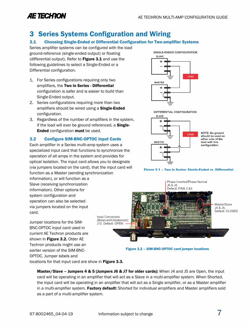
3.1 Choosing Single-Ended or Differential Configuration for Two-amplifier Systems Series amplifier systems can be configured with the load ground-reference (single-ended output) or floating (differential output). Refer to Figure 3.1 and use the following guidelines to select a Single-Ended or a Differential configuration.
For Series configurations requiring only two amplifiers, the Two in Series - Differential configuration is safer and is easier to build than Single-Ended output.
Series configurations requiring more than two amplifiers should be wired using a Single-Ended configuration.
Regardless of the number of amplifiers in the system, if the load will ever be ground referenced, a Single-Ended configuration must be used.
3.2 Configure SIM-BNC-OPTOC Input Cards Each amplifier in a Series multi-amp system uses a specialized input card that functions to synchronize the operation of all amps in the system and provides for optical isolation. The input card allows you to designate (via jumpers located on the card), that the input card will function as a Master (sending synchronization information), or will function as a Slave (receiving synchronization information). Other options for system configuration and operation can also be selected via jumpers located on the input card.
Jumper locations for the SIM-BNC-OPTOC input card used in current AE Techron products are shown in Figure 3.2. Older AE Techron products might use an earlier version of the SIM-BNC-OPTOC. Jumper labels and locations for that input card are show in Figure 3.3.
Master/Slave – Jumpers 4 & 5 (Jumpers J6 & J7 for older cards): When J4 and J5 are Open, the input card will be operating in an amplifier that will act as a Slave in a multi-amplifier system. When Shorted, the input card will be operating in an amplifier that will act as a Single amplifier, or as a Master amplifier in a multi-amplifier system. Factory default: Shorted for individual amplifiers and Master amplifiers sold as a part of a multi-amplifier system.
3 Series Systems Configuration and Wiring
Figure 3.2 – SIM-BNC-OPTOC card jumper locations
Figure 3.1 – Two in Series: Single-Ended vs. Differential

AE TECHRON MULTI-AMP CONFIGURATION GUIDE
8 Information subject to change 97-8002465_04-04-19
Input Connectors (Balanced/Unbalanced) – Jumper J12 (Jumper J4 for older cards): When Open, this option lifts the negative (–) leg from ground on both input connectors, allowing the Removable Barrier Block connector to be used as a balanced input and the BNC connector to be used as an unbalanced floating input. When Shorted, the negative (–) leg is tied to ground through a 2.7-ohm resistor, allowing either the BNC or the Removable Barrier Block connector to be used as an unbalanced grounded input. Refer to Figure 3.4 for additional information. Factory default: Open.
Slave Phase Inversion – Jumpers J6 & J8 (Jumpers J12 & J13 for older cards): When pins 2 and 3 are shorted on both jumpers, this option inverts the input signal, allowing a Slave amplifier to operate in the Two in Series – Differential configuration. When pins 1 and 2 are shorted on both jumpers, the input signal is not inverted, and the amplifier can operate as a Master amplifier or as a Slave for any Series – Single Ended configuration. Factory default: Pins 1 and 2 shorted.
3.2.1 Configure for Use in a Series – Single Ended configuration If you will be using a Series – Single Ended configuration for your system, complete the following:
For all except one SIM-BNC-OPTOC input card for your system, remove the shunts from the Master/Slave jumpers to configure the card(s) to operate as a Slave. For the remaining card, verify that the shunts are in place to configure the card to operate as a Master.
If desired, configure the Input Connectors (Balanced/Unbalanced) jumper on the Master input card to allow unbalanced input.
3.2.2 Configure for Use in a Two in Series – Differential configuration If you will be using the Two in Series - Differential configuration for your system, complete the following:
For one SIM-BNC-OPTOC input card for your system, remove the shunts from the Master/Slave jumpers to configure the card to operate as a Slave. For the remaining card, verify that the shunts are in place to configure the card to operate as a Master.
Figure 3.3 – Older SIM-BNC-OPTOC card jumper locations
Figure 3.4 – Input Connectors Wiring Diagram

AE TECHRON MULTI-AMP CONFIGURATION GUIDE
97-8002465_04-04-19 Information subject to change 9
On the SIM-BNC-OPTOC input card that is now configured for Slave operation, move the shunts positioned on pins 1 and 2 of both of the Slave Phase Inversion jumpers and place them on pins 2 and 3 of both jumpers. This will allow the input signal received by the Slave amplifier to be inverted.
If desired, configure the Input Connectors (Balanced/Unbalanced) jumper on the Master input card to allow unbalanced input.
3.3 Install SIM-BNC-OPTOC Input Cards in Amplifiers Before preparing the amplifiers, make sure the amplifier is turned off for at least 3-5 minutes and the AC mains are disconnected.
Locate the standard SIM-BNC Input Card on the right side of the rear panel of each amplifier.
Use a #2 Phillips screwdriver to remove and retain the two (2) screws located at the edges of the input card.
Unplug the ribbon cable from the back of the input card; remove the card from the amplifier card bay. For each amplifier, plug the ribbon cable into the ribbon connector on the SIM-BNC-OPTOC card. Reinstall
the card into the card bay on the amplifier back panel and secure in place using the retained screws. (optional) We recommend labeling each SIM-BNC-OPTOC card as “Master” or “Slave” to identify the
configuration of the installed input card.
3.4 Configure Amplifiers’ Main Boards for Slave Operation 2100/7000-Series amplifiers are configured by default for use as stand-alone (or Master) amplifiers. When creating a Series multiple amplifier system, you must also configure each amplifier’s main board for Slave operation on the amplifiers to be used as a Slave(s) in the system. Note that the main boards installed in the 2100 and 7000 Series models are identical, but the method for accessing the main board varies between models.
3.4.1 Accessing the Main Board on 2105/7212/7224 Amplifiers
2105, 7212 and 7224 amplifiers contain an Access Panel built into the top cover to allow easy access to the amplifier main board for configuration of the Master/Slave setting.
IMPORTANT: Before removing the Access Panel, make sure the amplifier is turned off for at least 3-5 minutes and the AC mains are disconnected.
On each Slave amplifier, locate the Access Panel as shown in Figure 3.5. Make sure that all 8 screws are accessible. Remove the unit from its rack, if necessary.
Using a #2 Phillips screwdriver, remove the eight (8) screws located on the top and side of the amplifier. Remove the Access Panel and set it aside.
3.4.2 Accessing the Main Board on 2110, 2120, 7548 or 7796 Amplifiers The 2110, 2120, 7548 or 7796 amplifier Main Board can be accessed by removing the amplifier front panel.
After turning the amplifier off, let the unit sit for 3-5 minutes before removing the input card or access panel. This will allow the electrical charge in the power supply capacitors to discharge.
Figure 3.5 – 2105/7212/7224 Amplifier Access Panel Screw Locations
Do not attempt to access the Main Board while the amplifier is running. Turn the amplifier off and disconnect the AC Mains before removing the input card or amplifier access panel.

AE TECHRON MULTI-AMP CONFIGURATION GUIDE
10 Information subject to change 97-8002465_04-04-19
IMPORTANT: Before removing the Front Panel, make sure the amplifier is turned off for at least 3-5 minutes and the AC mains are disconnected.
Turn the power to the amplifier “OFF”. Using a 1/8-inch hex driver, remove the four (4) hex-head
screws, located along the left and right edges of the amplifier front panel.
Remove the front cover by pulling straight towards you.
3.4.3 Set Master/Slave Jumpers On the main board, locate the jumpers P1 and P2
(Master/Slave). For Slave operation, set both jumpers to the DOWN position (lower two pins shorted). See Figure 3.6 for jumper locations.
3.5 Remove Output Terminal Resistor For all Series – Single Ended Output configurations, it is important to remove the output terminal resistor from all Slave amplifiers in the system.
On each Slave amplifier back panel, locate and remove the resistor connecting the terminals labeled COM (2105/ 7212/7224 amplifier) or SAMPLED COMMON (2110/ 2120/7548/7796 amplifiers) and CHASSIS GROUND on the output connector. See Figures 3.7 and 3.8.
Retain the resistor for later use.
3.6 Attach Master/Slave Labels (optional) We recommended labeling each amplifier front panel as “Master” or “Slave to identify the configuration of the amplifier.
3.7 Series System Wiring Locate the Series configuration that you have selected to meet your application requirements: Section 3.8 for a Two-in-Series – Differential configuration or Section 3.9 for a Two-in-Series – Open-Ended configuration. Then follow the steps provided to wire and test your 7000-Series Multi-amp System.
3.8 Two in Series – Differential Complete the following procedures to connect your amplifiers for Two in Series - Differential operation.
3.8.1 Connect and Test DC Offset and Interlock Using a DB-9 high-voltage interlock cable, connect from the
MASTER OUTPUT connector on the SIM-BNC-OPTOC card of the Master amplifier to the SLAVE INPUT connector on the SIM-BNC-OPTOC card of the Slave amplifier.
Using wiring appropriate for your application, load and expected output, connect from the MASTER amplifier’s back-panel output connector labeled COM
Figure 3.6 – Master/Slave Jumper Locations
Figure 3.7 – 2105/7212/7224 Output Terminal Resistor
ELECTRIC SHOCK HAZARD. Output potentials from the amplifiers can be lethal. Make connections only with amplifiers’ AC power OFF and input signals removed.
Figure 3.8 – 2110/2120/7548/7796 Output Terminal Resistor

AE TECHRON MULTI-AMP CONFIGURATION GUIDE
97-8002465_04-04-19 Information subject to change 11
(2105/7212/7224) or SAMPLED COMMON (2110/2120/7548/7796) to the SLAVE amplifier’s COM/SAMPLED COMMON connector.
On the MASTER amplifier, connect the output wiring to the back-panel output connector labeled OUTPUT. On the SLAVE amplifier, connect the output wiring to the back-panel output connector labeled OUTPUT. IMPORTANT: DO NOT connect the load at this time.
Terminate the input of the Master amplifier using the resistor-terminated barrier block connector (see Figure 3.9) or similar device.
Power up each amplifier by switching to ON the front-panel ON/OFF switch (2105/7212/7224 amplifiers) or moving the back-panel AC Mains Switch/Circuit Breaker to the ON (up) position (2110/2120/7548/7796 amplifiers). Allow the amplifiers to come to the Ready state. When Ready, the amplifier Ready and Run LEDs will be lit. Note: Some amplifiers that have been custom-configured may require that you press the Enable button to bring the amplifier to the Ready state. Let the amplifiers run for several minutes in Ready state to allow DC offsets to stabilize.
Using a digital voltmeter set to DC, measure across each amplifier’s back-panel output connector terminals (OUTPUT to COM or SAMPLED COMMON) to verify that the DC offset of each amplifier is less than 10 mVdc. See Figure 3.10. NOTE: If any amplifier’s DC offset is greater than 10 mVdc, the amplifier may require servicing. Contact AE Techron Technical Support.
On the Master amplifier only, press the Stop button to place the amplifier in Standby mode. Verify that both Master and Slave amplifier enter Standby mode (Standby LED is lit).
Figure 3.9 – Terminating the Amplifier Input
Figure 3.10 – Verifying DC Offset

AE TECHRON MULTI-AMP CONFIGURATION GUIDE
12 Information subject to change 97-8002465_04-04-19
3.8.2 Test Amplifier Gain With the amplifiers in Standby mode, remove the input signal terminator and connect a signal generator
to the BNC or Removable Barrier Block connector on the SIM-BNC-OPTOC card of the MASTER amplifier ONLY.
Enable the amplifiers (place in Run mode), and then apply a sine wave of 5 Vrms at 100 Hz at the Master amplifier input. Using a voltmeter, measure across each amplifier’s back-panel output connector terminals (OUTPUT to COM or SAMPLED COMMON) to verify an output from each amplifier of approximately 100 Vrms (gain of 20). See Figure 3.11. NOTE: If any amplifier’s gain varies significantly from the set gain of 20, the amplifier may require servicing. Contact AE Techron Technical Support.
Figure 3.11 – Verifying Amp Gain

AE TECHRON MULTI-AMP CONFIGURATION GUIDE
97-8002465_04-04-19 Information subject to change 13
3.8.3 Connect Load and Test System Output Power down the amplifiers. Connect the two output wires leading from the MASTER and SLAVE OUTPUT connectors to your load. Power up both amplifiers and allow them to come to the Ready state. Apply a sine wave of 5 Vrms at 100 Hz at the Master amplifier input. Using a voltmeter, measure across
the system load to verify an output from the system of approximately 200 Vrms. See Figure 3.12. Check the completed system diagram in Figure 3.13 to verify proper system setup. Turn input signal up to the level required for your application.
‘
Figure 3.12 – Verifying System Gain
AE TECHRON MULTI-AMP CONFIGURATION GUIDE
14 Information subject to change 97-8002465_04-04-19
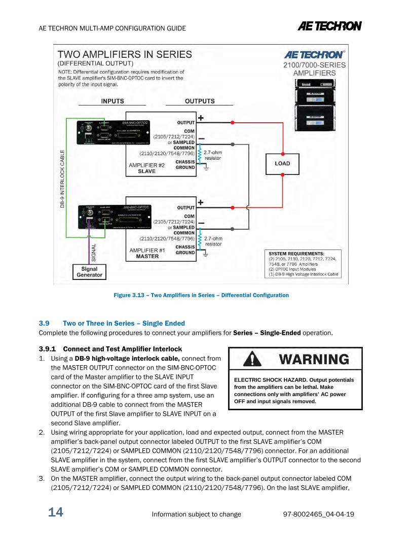
Figure 3.13 – Two Amplifiers in Series – Differential Configuration
3.9 Two or Three in Series – Single Ended Complete the following procedures to connect your amplifiers for Series – Single-Ended operation.
3.9.1 Connect and Test Amplifier Interlock Using a DB-9 high-voltage interlock cable, connect from
the MASTER OUTPUT connector on the SIM-BNC-OPTOC card of the Master amplifier to the SLAVE INPUT connector on the SIM-BNC-OPTOC card of the first Slave amplifier. If configuring for a three amp system, use an additional DB-9 cable to connect from the MASTER OUTPUT of the first Slave amplifier to SLAVE INPUT on a second Slave amplifier.
Using wiring appropriate for your application, load and expected output, connect from the MASTER amplifier’s back-panel output connector labeled OUTPUT to the first SLAVE amplifier’s COM (2105/7212/7224) or SAMPLED COMMON (2110/2120/7548/7796) connector. For an additional SLAVE amplifier in the system, connect from the first SLAVE amplifier’s OUTPUT connector to the second SLAVE amplifier’s COM or SAMPLED COMMON connector.
On the MASTER amplifier, connect the output wiring to the back-panel output connector labeled COM (2105/7212/7224) or SAMPLED COMMON (2110/2120/7548/7796). On the last SLAVE amplifier,
ELECTRIC SHOCK HAZARD. Output potentials from the amplifiers can be lethal. Make connections only with amplifiers’ AC power OFF and input signals removed.

AE TECHRON MULTI-AMP CONFIGURATION GUIDE
97-8002465_04-04-19 Information subject to change 15
connect the output wiring to the back-panel output connector labeled OUTPUT. IMPORTANT: DO NOT connect the load at this time.
Terminate the input of the Master amplifier using a resistor-terminated barrier block connector (see Figure 3.14) or similar device.
Power up each amplifier by switching to ON the front-panel ON/OFF switch (2105/7212/7224 amplifiers) or moving the back-panel AC Mains Switch/Circuit Breaker to the ON (up) position (2110/2120/7548/7796 amplifiers). Allow the amplifiers to come to the Ready state. When Ready, the amplifier Ready and Run LEDs will be lit. Note: Some amplifiers that have been custom-configured may require that you press the Enable button to bring the amplifier to the Ready state. Let the amplifiers run for several minutes in Ready state to allow DC offsets to stabilize.
Using a digital voltmeter set to DC, measure across each amplifier’s back-panel output connector terminals (OUTPUT to COM or SAMPLED COMMON) to verify that the DC offset of each amplifier is less than 10 mVdc. See Figure 3.15. NOTE: If any amplifier’s DC offset is greater than 10 mVdc, the amplifier may require servicing. Contact AE Techron Technical Support.
On the Master amplifier only, press the Stop button to place the amplifier in Standby mode. Verify that both Master and Slave amplifier enter Standby mode (Standby LED is lit).
Figure 3.14 – Terminating the Amplifier Input
Figure 3.15 – Verifying DC Offset

AE TECHRON MULTI-AMP CONFIGURATION GUIDE
16 Information subject to change 97-8002465_04-04-19
3.9.2 Test Amplifier Gain With the amplifiers in Standby mode, remove the input signal termination and connect a signal generator
to the BNC or Removable Barrier Block connector on the SIM-BNC-OPTOC card of the MASTER amplifier ONLY.
Apply a sine wave of 5Vrms at 100 Hz at the Master amplifier input. Using a voltmeter measure across each amplifier’s back-panel output connector terminals (OUTPUT to COM or SAMPLED COMMON) to verify an output from each amplifier of approximately 100Vrms (gain of 20). See Figure 3.16. NOTE: If any amplifier’s gain varies significantly from the set gain of 20, the amplifier may require servicing. Contact AE Techron Technical Support.
3.9.3 Connect Amplifiers and Load Power down the amplifiers. Connect the two output wires leading from the MASTER amplifier’s COM/SAMPLED COMMON connector
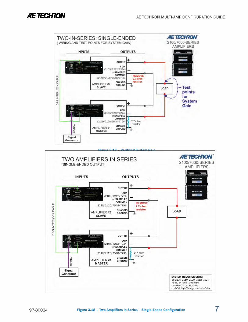
and last SLAVE amplifier’s OUTPUT connector to your load. Power up all amplifiers and allow them to come to the Ready state. Apply a sine wave of 5Vrms at 100 Hz at the Master amplifier input. Using a voltmeter, measure across
the system load to verify an output from the system of approximately 200Vrms. See Figure 3.17. Check the completed system diagrams in Figure 3.18 or 3.19 to verify proper system setup. Turn input signal up to the level required for your application.
Figure 3.16 – Verifying Amp Gain
AE TECHRON MULTI-AMP CONFIGURATION GUIDE
97-8002465_04-04-19 Information subject to change 17
Figure 3.17 – Verifying System Gain
Figure 3.18 – Two Amplifiers in Series – Single-Ended Configuration

AE TECHRON MULTI-AMP CONFIGURATION GUIDE
18 Information subject to change 97-8002465_04-04-19
Figure 3.19 – Three Amplifiers in Series – Single-Ended Configuration

AE TECHRON MULTI-AMP CONFIGURATION GUIDE
97-8002465_04-04-19 Information subject to change 19
4 Parallel Systems Configuration, Wiring and Balancing Parallel multi-amp configurations require a ballast resistor (two resistors for 2120 and 7796 models) to be mounted on each amplifier’s back panel and connected to the amplifier’s OUTPUT connector. Complete the following steps for each amplifier in your system to install the ballast resistors for Parallel System setup.
Before preparing the amplifiers, make sure the amplifier is turned off for at least 3-5 minutes and the AC mains are disconnected.
4.1 Install Ballast Resistors
4.1.1 Remove Amplifier Top Cover Instructions for removing the top covers on all 7000-series amplifier models are available on the AE Techron website at www.aetechron.com/SupportLit.shtml.
4.1.2 Mount and Connect Ballast Resistor Locate the bracket-mounted ballast resistor(s) and
mounting hardware (bolts, washers and nuts) in the Ballast Resistor Kit. For each mounting hole, slide one washer onto the bolt, and then insert the bolt in the mounting hole.
Position the bracket on the amplifier back-panel grill as shown in Figures 4.1 and 4.2.
Insert the bolts through the back-panel grill until they are flush with the mounting bracket.
Slide a second washer over the threaded portion of each bolt (inside the amplifier case).
Apply thread-lock to the threads of each bolt. Thread a nut onto each bolt and tighten down, securing the bracket to the back panel. Connect the resistor’s terminal lead(s) to the output connector labeled OUTPUT as shown in Figures 4.3
and 4.4. Tighten the screw to secure. DO NOT replace the top cover or front panel until you have completed the addition preparation steps in
this section.
Do not attempt to remove the amplifier top cover while the amplifier is running. Turn the amplifier off and disconnect the AC Mains before removing the cover. After turning the amplifier off, let the unit sit for 3-5 minutes to allow the electrical charge in the power supply capacitors to discharge.
Before preparing the amplifiers, make sure the amplifier is turned off and the AC mains are disconnected. Let the unit sit for 3-5 minutes to allow the electrical charge in the power supply capacitors to discharge.
Figure 4.1 – 2105/7224 Ballast Resistor Mounting
Figure 4.2 – 2120/7796 Ballast Resistor Mounting
SHOCK/BURN HAZARD. DO NOT TOUCH BALLAST RESISTORS while the system is operating. The ballast resistors are not protected against electrical or heat transfer. Touching the ballast resistors during operation can result in severe shock or burn.
AE TECHRON MULTI-AMP CONFIGURATION GUIDE
20 Information subject to change 97-8002465_04-04-19
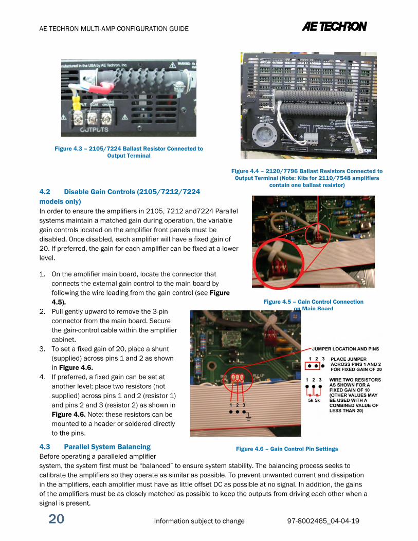
4.2 Disable Gain Controls (2105/7212/7224 models only) In order to ensure the amplifiers in 2105, 7212 and7224 Parallel systems maintain a matched gain during operation, the variable gain controls located on the amplifier front panels must be disabled. Once disabled, each amplifier will have a fixed gain of 20. If preferred, the gain for each amplifier can be fixed at a lower level.
On the amplifier main board, locate the connector that connects the external gain control to the main board by following the wire leading from the gain control (see Figure 4.5).
Pull gently upward to remove the 3-pin connector from the main board. Secure the gain-control cable within the amplifier cabinet.
To set a fixed gain of 20, place a shunt (supplied) across pins 1 and 2 as shown in Figure 4.6.
If preferred, a fixed gain can be set at another level; place two resistors (not supplied) across pins 1 and 2 (resistor 1) and pins 2 and 3 (resistor 2) as shown in Figure 4.6. Note: these resistors can be mounted to a header or soldered directly to the pins.
4.3 Parallel System Balancing Before operating a paralleled amplifier system, the system first must be “balanced” to ensure system stability. The balancing process seeks to calibrate the amplifiers so they operate as similar as possible. To prevent unwanted current and dissipation in the amplifiers, each amplifier must have as little offset DC as possible at no signal. In addition, the gains of the amplifiers must be as closely matched as possible to keep the outputs from driving each other when a signal is present.
Figure 4.5 – Gain Control Connection on Main Board
Figure 4.6 – Gain Control Pin Settings
Figure 4.3 – 2105/7224 Ballast Resistor Connected to Output Terminal
Figure 4.4 – 2120/7796 Ballast Resistors Connected to Output Terminal (Note: Kits for 2110/7548 amplifiers
contain one ballast resistor)
AE TECHRON MULTI-AMP CONFIGURATION GUIDE
97-8002465_04-04-19 Information subject to change 21
Balancing of 2100/7000-Series amplifiers is performed using trim pots located on the amplifier main boards. For 2105, 7212 and 7224 models, the main board will be accessible when the top cover is removed for ballast resistor installation. For 2110, 2120, 7548, 7794 and 7796 models, the main board will be accessible when the front panel is removed, which is also required for ballast resistor installation on these models.
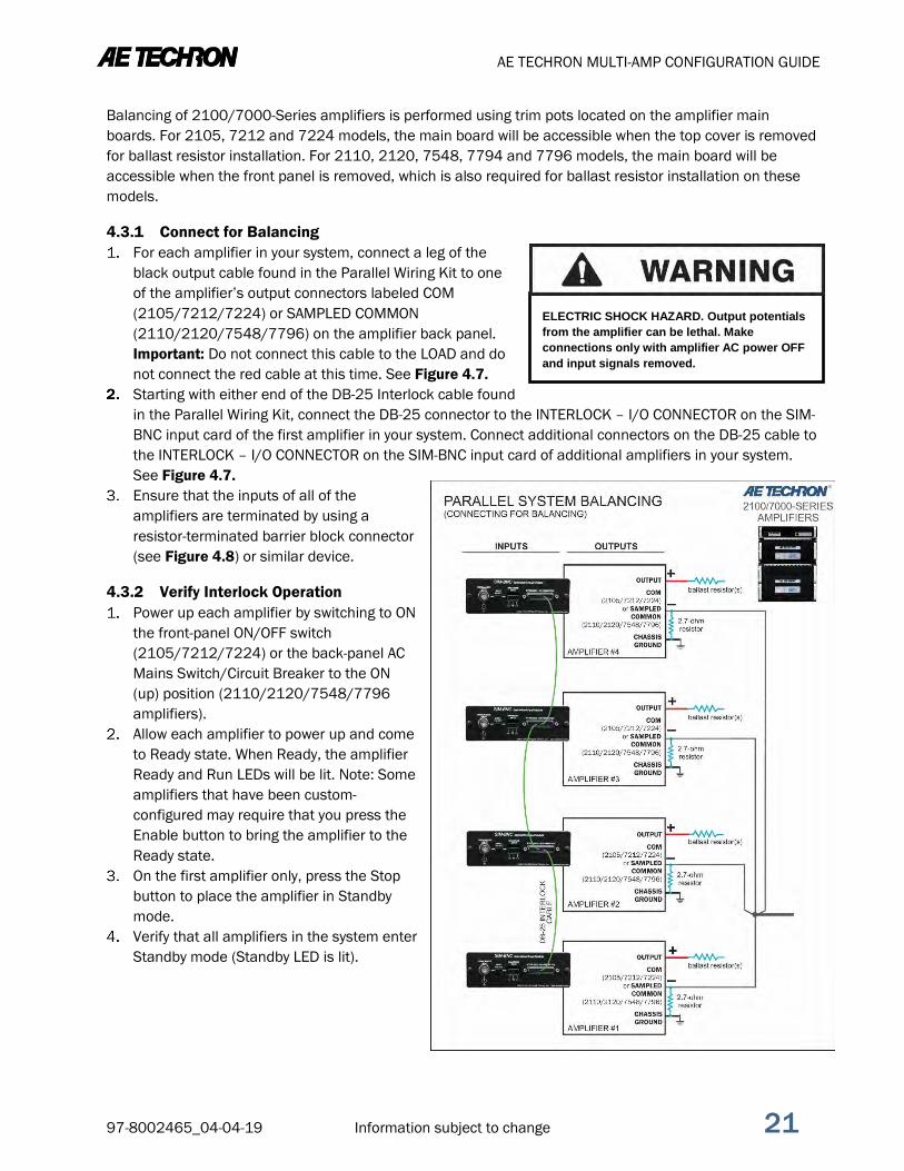
4.3.1 Connect for Balancing For each amplifier in your system, connect a leg of the
black output cable found in the Parallel Wiring Kit to one of the amplifier’s output connectors labeled COM (2105/7212/7224) or SAMPLED COMMON (2110/2120/7548/7796) on the amplifier back panel. Important: Do not connect this cable to the LOAD and do not connect the red cable at this time. See Figure 4.7.
Starting with either end of the DB-25 Interlock cable found in the Parallel Wiring Kit, connect the DB-25 connector to the INTERLOCK – I/O CONNECTOR on the SIM-BNC input card of the first amplifier in your system. Connect additional connectors on the DB-25 cable to the INTERLOCK – I/O CONNECTOR on the SIM-BNC input card of additional amplifiers in your system. See Figure 4.7.
Ensure that the inputs of all of the amplifiers are terminated by using a resistor-terminated barrier block connector (see Figure 4.8) or similar device.
4.3.2 Verify Interlock Operation Power up each amplifier by switching to ON
the front-panel ON/OFF switch (2105/7212/7224) or the back-panel AC Mains Switch/Circuit Breaker to the ON (up) position (2110/2120/7548/7796 amplifiers).
Allow each amplifier to power up and come to Ready state. When Ready, the amplifier Ready and Run LEDs will be lit. Note: Some amplifiers that have been custom-configured may require that you press the Enable button to bring the amplifier to the Ready state.
On the first amplifier only, press the Stop button to place the amplifier in Standby mode.
Verify that all amplifiers in the system enter Standby mode (Standby LED is lit).
ELECTRIC SHOCK HAZARD. Output potentials from the amplifier can be lethal. Make connections only with amplifier AC power OFF and input signals removed.
Figure 4.7 – Connecting for Balancing (Four in Parallel shown)

AE TECHRON MULTI-AMP CONFIGURATION GUIDE
22 Information subject to change 97-8002465_04-04-19
4.3.3 Adjust DC Offset Power down all amplifiers. On each amplifier main board, locate the Amp
Offset (R65) (see Figure 4.9). Ensure that all amplifier inputs are terminated by
using a resistor-terminated barrier block connector (see Figure 4.8) or similar device.
Power up all amplifiers in the system and run the amplifiers for several minutes in Ready state to allow DC offsets to stabilize.
Using a digital voltmeter set to DC, measure across the amplifier’s back-panel output connector terminals (OUTPUT to COM or SAMPLED COMMON) to verify that the DC offset of each amplifier is less than 5 mVdc. See Figure 4.10.
If the DC offset for any amplifier is greater than 5 mVdc, adjust each amplifier using the Amp Offset (R65) on the amplifier main board. Adjust each amplifier’s DC offset to read as closely as possible to zero.
4.3.4 Wire and Connect Parallel Inputs IMPORTANT FOR 2105, 7212 and 7224 PARALLEL SYSTEMS: In order to ensure the amplifiers used in a 2105, 7212 or 7224 Parallel system maintain a matched gain while operating, the variable gain controls located on each amplifier’s front panel must be disabled. Refer to Section 4.2 to complete this process before connecting the inputs to your system.
Power down the amplifiers. Remove all amplifier input terminations. Use the jump wires included in the Parallel Wiring Kit and the Removable Barrier Block connectors that
ship with each amplifier to create a paralleled input signal wire as shown in Figure 4.11. Wire one input connector for each amplifier in your system.
You can use balanced wiring (shown), or you can build the wire for unbalanced input. If using unbalanced wiring, switch the INPUT SELECT switch located on the SIM-BNC input card on each amplifier to the LEFT position (unbalanced setting).
Alternately, you can connect an unbalanced input signal to the SIM-BNC’s BNC input connector using the optional BNC PARALLEL INPUT KIT as shown in Figure 4.12. Set the INPUT SELECT switch located on the SIM-BNC input card on each amplifier to the LEFT position (unbalanced setting).
Connect the input wire to a signal generator and to each amplifier in your system.
Figure 4.9 – Main Board Balancing Control Locations
Figure 4.8 – Terminating the Amplifier Input

AE TECHRON MULTI-AMP CONFIGURATION GUIDE
97-8002465_04-04-19 Information subject to change 23
4.3.5 Verify and Adjust Amplifier Gain On the main board of each amplifier, locate the Amp Gain Trim (R210) (see Figure 4.9). Connect a digital voltmeter set to AC volts between the OUTPUT and COM terminals of the first amplifier.
See Figure 4.13. Power up the first amplifier. Apply a sine wave to the amplifier input of approximately 5Vrms (100-500 Hz). This should result in
about 100Vrms output from the amplifier (assuming a fixed gain of 20). If voltmeter indicates an output greater or lesser than 100 Vrms, adjust Amp Gain Trim (R210) to correct. Power up and repeat this procedure for the second amplifier and all other amplifiers in your system.
Figure 4.12 – Optional BNC Parallel Input Wiring
(Three in Parallel shown)
Figure 4.11 – Wiring the Paralleled Input Wire
Figure 4.10 – Wiring and Test Points for DC Offset

AE TECHRON MULTI-AMP CONFIGURATION GUIDE
24 Information subject to change 97-8002465_04-04-19
4.3.6 Amplifier Gain Matching Connect a digital voltmeter set to AC volts between the positive outputs of the first and the second
amplifier (see Figure 4.14). Adjust Amp Gain Trim (R210) on the second amplifier for minimum AC voltage (millivolts). Repeat the process of checking gain between the first amplifier and any additional amplifiers in your
system. Continue checking and adjusting until the gain of all amplifiers in the system is matching to within
millivolts.
Figure 4.13– Wiring and Test Points for Amp Gain

AE TECHRON MULTI-AMP CONFIGURATION GUIDE
97-8002465_04-04-19 Information subject to change 25
Figure 4.14– Wiring and Test Points for Gain Matching

AE TECHRON MULTI-AMP CONFIGURATION GUIDE
26 Information subject to change 97-8002465_04-04-19
4.3.7 Verify Minimal Circulating Currents Power down the amplifiers. On each amplifier, connect one ring terminal end of your
RED output cable to the ballast resistor on each amplifier back panel. Note: Do not connect the LOAD at this time.
Using a digital voltmeter set to AC volts, connect between the positive outputs of the first and second amplifier (OUTPUT to OUTPUT). Starting with an input level of 0.5 Vrms, verify a meter reading of less than 50 mV. (50 mV corresponds to 0.5A of circulating current.) Check any additional amplifiers in your system.
Continue to monitor the DVM readings while turning signal input level up to the level required for your application.
4.3.8 Verify Current Sharing Power down the amplifiers. Connect your load to the two output cables. Connect the positive terminal of your load to the red cable
connected to the amplifier ballast resistors. Connect the negative terminal of your load to the black cable connected to the amplifier COM terminals.
Check to ensure that all system wiring has been correctly installed as shown in the following system diagrams (see Figure 4.15, 4.16 or 4.17).
Starting with a signal input approximately 10% of the typical input required for your application, power up the amplifiers.
Using a digital voltmeter set to AC volts, connect between the positive outputs of the amplifiers (Amplifier #1 OUTPUT to Amplifier #2 OUTPUT). Verify a meter reading of less than 200 mV, up to the typical power level for the application. (200 mV corresponds to 2A of circulating current.) Check additional amplifiers in your system.
Continue to monitor the DVM readings while turning signal input level up to the level required for your application.
ELECTRIC SHOCK HAZARD. Output potentials from the amplifiers can be lethal. Make connections only with amplifiers’ AC power OFF and input signals removed.

AE TECHRON MULTI-AMP CONFIGURATION GUIDE
97-8002465_04-04-19 Information subject to change 27
Figure 4.16– Three Amplifiers Paralleled
Figure 4.15 – Two Amplifiers Paralleled

AE TECHRON MULTI-AMP CONFIGURATION GUIDE
28 Information subject to change 97-8002465_04-04-19
Figure 4.17 – Four Amplifiers Paralleled

AE TECHRON MULTI-AMP CONFIGURATION GUIDE
97-8002465_04-04-19 Information subject to change 29
Appendix A: Wire Current-Carrying Capacity Wire size or gauge should be selected to exceed the expected current it will carry. The chart below shows the minimum matching requirements of wire gauge and continuous duty amperage limits.
*Minimum value for insulated wire in free air (i.e. not bundled).
Figure A-1 – Wire Current-Carrying Capacity Chart
Continuous Duty Current* (Amperes)
American Wire Gauge (AWG)
Diameter (mm)
Diameter Mils (.001 in)
200 000 10.40 410
175 00 9.27 365
150 0 8.25 325
125 1 7.35 289
100 2 6.54 258
80 4 5.19 204
60 6 4.12 162
46 8 3.26 128
33 10 2.59 102
23 12 2.05 81
17 14 1.63 64
13 16 1.29 51
10 18 1.02 40
AE TECHRON MULTI-AMP CONFIGURATION GUIDE
30 Information subject to change 97-8002465_04-04-19
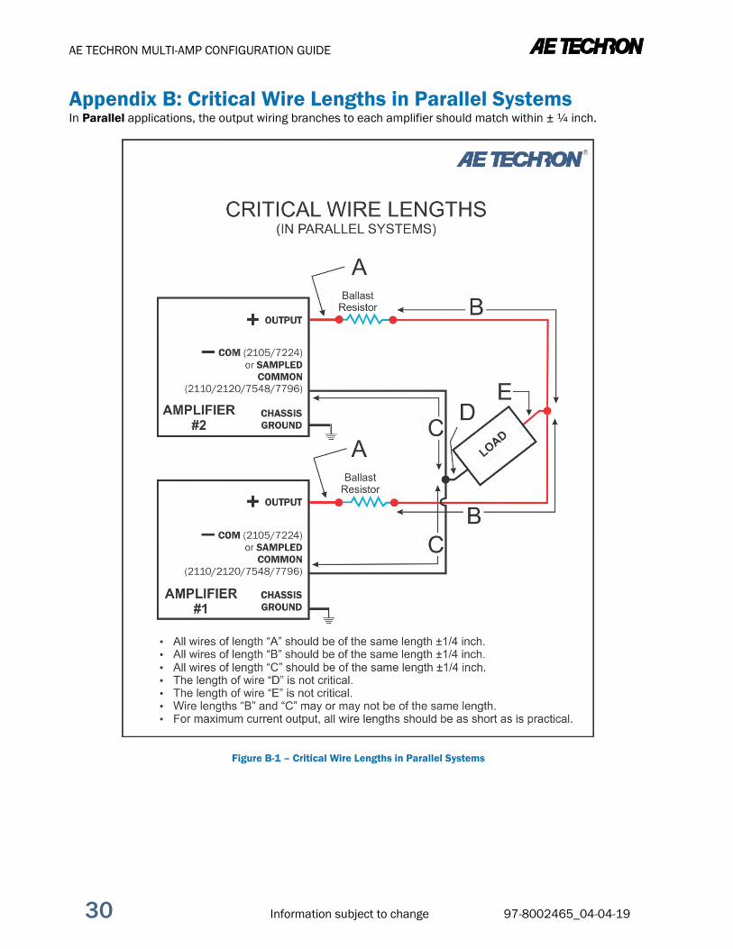
Appendix B: Critical Wire Lengths in Parallel Systems In Parallel applications, the output wiring branches to each amplifier should match within ± ¼ inch.
Figure B-1 – Critical Wire Lengths in Parallel Systems

AE TECHRON MULTI-AMP CONFIGURATION GUIDE
97-8002465_04-04-19 Information subject to change 31
Appendix C: Building Parallel System Output Cables The Parallel Wiring Kits available through AE Techron include pre-built cables to be used for Output connections. This section describes how to build your own output cables, if you so choose.
Select wire appropriate for your application, load and expected output. For 2105, 7212 or 7224 Parallel systems, 10 AWG wire will be suitable for most applications. For 2110 or 7548 Parallel systems, 8 AWG wire will typically be required. 2120 or 7796 Parallel systems with a high-impedance load and continuous output at less than 60 Arms can typically be wired with 6 AWG wire. However for 7796 systems running high-current, continuous-duty applications, #4 welding wire may be necessary.
If a jump wire is used to connect from the parallel output cables to the load, it should be capable of carrying the expected total current output of the system. See Appendix A: Wire Current-Carrying Capacity for assistance in determining the requirements for your system.
IMPORTANT: In a paralleled system, it is important to control the lengths of output cables. Output cables should be between 2.5 and 4.0 feet in length, and the lengths of each leg of the output cables should match within ±1/4-inch. See Appendix B: Critical Wire Lengths, for information on critical cable lengths for paralleled systems.
Build two cables for output wiring. Each cable should contain one leg for each amplifier in your system. Color-code the cables using RED for the cable to connect to the positive terminal of the load; use BLACK for the cable to connect to the ground terminal of the load.
The wires should be terminated at one end into a spade lug, ring terminal or other terminal suitable for the system output and adaptable to the connectors on the load.
Terminate each of the legs of the RED cable with ring terminal ends to facilitate connection to each ballast resistor.
The legs of the BLACK cable should be un-terminated to facilitate connection into the amplifier’s barrier block COM connector.
See Figure C-1 for sample output cables (used for a two-in-parallel system).
Figure C-1 – Output Cables constructed for use in a
Two-in-Parallel System

AE TECHRON MULTI-AMP CONFIGURATION GUIDE
32 Information subject to change 97-8002465_04-04-19
Appendix D: Building the DB-25 Interlock Cable Parallel Wiring Kits are available through AE Techron that include a pre-built cable to be used for the Interlock connections. This section describes how to build your own DB-25 cable, if you so choose.
Using DB-25 connectors and light-gauge, single-conductor, shielded wire, build a cable as shown in Figure D-1.
On each connector, connect to Pin 4. On one of the end DB-25 connectors, attach the shield to Pin 17. Label this connector for use on
Amplifier #1 in the system.
Figure D-1 – DB-25 Cable Wiring for a Four-in-Parallel System

AE TECHRON MULTI-AMP CONFIGURATION GUIDE
97-8002465_04-04-19 Information subject to change 33
Appendix E: Returning Slave Amplifiers to Stand-Alone Use The configuration settings required for Series system operation must be returned to the factory-default settings before a Slave amplifier can be used as a stand-alone amplifier. To reconfigure your Slave amplifiers for stand-alone use, complete the following.
Amplifier Main Board Settings IMPORTANT: Before accessing the Main Board, make sure the amplifier is turned off for at least 3-5 minutes and the AC mains are disconnected.
Accessing the 2105/7212/7224 Amplifier Main Board 2105, 7212 and 7224 amplifiers contain an Access Panel built into the top cover to allow easy access to the amplifier main board for configuration of the Master/Slave setting.
On each 2105/7212/7224 amplifier that has been configured for Slave operation, locate the Access Panel as shown in Figure E-1. Make sure that all 8 screws are accessible. Remove the unit from its rack, if necessary.
Using a #2 Phillips screwdriver, remove the 8 screws located on the top and side of the amplifier.
Remove the Access Panel and set it aside.
Accessing the Main Board on 2110/2120/7548/7796 Amplifiers The 2110, 2120, 7548 or 7796 amplifier Main Board can be accessed by removing the amplifier front panel.
Turn the power to the amplifier “OFF”. Remove the four hex-head screws, located along the left
and right edges of the amplifier front panel. Remove the front cover by pulling straight towards you.
Set Master/Slave Jumpers On the main board, locate the jumpers P1 and P2 (Master/Slave). For Master operation, set both jumpers to the UP position (upper two pins shorted). See FigureE-2 for jumper locations.
Re-install Output Terminal Resistor For each Slave amplifier that has been configured for Series – Single Ended Output configurations, it is important to re-install the output terminal resistor.
On each Slave amplifier back panel, re-install the resistor connecting the terminals labeled COM (2105, 7212 and 7224 amplifiers) or SAMPLED COMMON (2110, 2120, 7548 and 7796 amplifiers) and CHASSIS GROUND on the output connector. See Figures E-3 and E-4.
Figure E-3 – 2105/7212/7224 Output Terminal Resistor
Figure E-1 – 2105/7212/7224 Access Panel Screw Locations
Figure E-2 – Master/Slave Jumper Locations
Figure E-4 – 2110/2120/7548/7796 Output Terminal Resistor

AE TECHRON MULTI-AMP CONFIGURATION GUIDE
34 Information subject to change 97-8002465_04-04-19
Figure E-5 – SIM-BNC-OPTOC, Factory Default Settings
Figure E-6 – SIM-BNC-OPTOC, Factory Default Settings for older input card version
Remove Slave Labels (optional) We recommended removing any “Slave” amplifier labels to avoid later confusion or errors.
Reconfigure SIM-BNC-OPTOC Cards. Refer to Figure E-5 or E-6 for SIM-BNC-OPTOC factory-default settings. Note that for normal stand-alone operation of an amplifier, the Master/Slave jumpers should be returned to the factory defaults. Stand-alone amplifiers can operate with Input Connectors (Balanced/Unbalanced) jumpers set to either OPEN or CLOSED, depending on the user’s preference. Phase Inverted/Phase Normal jumpers are not active when a SIM-BNC-OPTOC card is configured for stand-alone/master use, so the setting of this jumpers will not affect stand-alone operation.
2100- and 7000-Series amplifiers can operate as stand-alone amplifiers using the SIM-BNC-OPTOC as the input card. Or, if you prefer, the SIM-BNC-OPTOC card can be removed and the standard SIM-BNC input card re-installed for stand-alone use.