Embed Size (px)
Citation preview

Installation And Operation Instructions
For LPS Series Inverter Power Systems Models: LPS-375 and LPS-600
True SinusoidalOutput Power
LPS-375 Model
LPS-600 Model

READ AND FOLLOW ALL SAFETY INSTRUCTIONS
IMPORTANT SAFEGUARDSWhen using electrical equipment, basic safety precautions should always be followed, includ-ing the following:
READ AND FOLLOW ALL SAFETY INSTRUCTIONS:• Do not use outdoors.
• Do not let power supply cords touch hot surfaces.
• Do not mount near gas or electric heaters.
• Use caution when servicing batteries. Battery acid can cause burns to skin and eyes. Ifacid is spilled on skin or in eyes, flush acid with fresh water and contact a physician immedi-ately.
• Equipment should be mounted securely in locations and at heights where it will not be read-
ily subjected to tampering by unauthorized personnel.
• The use of accessory equipment not recommended by the MANUFACTURER may cause anunsafe condition.
• The AC voltage rating of this equipment is specified on the product label. Do not connectequipment to any other voltage.
• Do not use this equipment for other than its intended purpose.
• Servicing of this equipment should be performed by qualified service personnel.
SAVE THESE IMPORTANT SAFETY INSTRUCTIONS
The installation and use of this product must comply with all national, federal, state, munici-pal, or local codes that apply.
Please read this manual thoroughly before operating the LPS Inverter System.
2.

3.
Table of ContentsDescription Page
Section 100 System Installation Instructions101. Specifications ....................................................................................................... 4102. Receiving, Moving and Storing Systems and Batteries ...................................... 5102.1 Shipping Damage ................................................................................................ 5102.2 Temporary Storage of Units and Batteries ........................................................... 5103. Installation Requirements .................................................................................... 5103.1 Operating Environment ........................................................................................ 5103.2 High Altitude Operation ........................................................................................ 5104. Cabinet Mounting ................................................................................................ 5104.1 Tools Required ..................................................................................................... 5104.2 Mounting Hardware .............................................................................................. 6104.3 Knockout Locations .............................................................................................. 6104.4 Cabinet Mounting................................................................................................. 6105. AC Connections .................................................................................................. 6105.1 AC Wiring Preparations ....................................................................................... 7105.2 AC Input Voltage Selector Plug Installation ......................................................... 7105.3 AC Input/output Wiring Connections to Terminal Block ....................................... 7 106. Battery Information ................................................................................................9106.1 Tools ......................................................................................................................9106.2 Battery installation and Connection ................................................................... 10106.3 Battery Voltage Check ........................................................................................12107. Final Installation Checklist ..................................................................................12108. System Start-Up Procedure ................................................................................12109. System Test ........................................................................................................12
Section 200Maintenance200.1 Safe Shut Down Procedure ............................................................................... 14200.2 Routine System Maintenance ............................................................................ 14200.3 Manual Routine Inverter Tests ........................................................................... 14200.4 Routine Battery Inspection and Maintenance .................................................... 15200.5 Battery Replacement Procedure........................................................................ 15200.6 Battery Disposal................................................................................................. 15
110. System Self Test / Diagnostics ...........................................................................13110.1 Self Test / Diagnostic Functions .........................................................................13110.2 Self Test / Diagnostic Indication..........................................................................13
4.
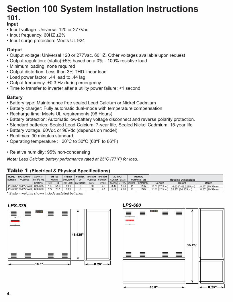
Section 100 System Installation Instructions101. �������Input• Input voltage: Universal 120 or 277Vac.• Input frequency: 60HZ ±2%• Input surge protection: Meets UL 924
Output• Output voltage: Universal 120 or 277Vac, 60HZ. Other voltages available upon request• Output regulation: (static) ±5% based on a 0% - 100% resistive load• Minimum loading: none required• Output distortion: Less than 3% THD linear load• Load power factor: .44 lead to .44 lag• Output frequency: ±0.3 Hz during emergency• Time to transfer to inverter after a utility power failure: <1 second
Battery• Battery type: Maintenance free sealed Lead Calcium or Nickel Cadmium• Battery charger: Fully automatic dual-mode with temperature compensation• Recharge time: Meets UL requirements (96 Hours)• Battery protection: Automatic low-battery voltage disconnect and reverse polarity protection.• Standard batteries: Sealed Lead-Calcium: 7-year life, Sealed Nickel Cadmium: 15-year life• Battery voltage: 60Vdc or 96Vdc (depends on model)• Runtimes: 90 minutes standard.• Operating temperature : 20ºC to 30ºC (68ºF to 86ºF)
• Relative humidity: 95% non-condensing
Note: Lead Calcium battery performance rated at 25°C (77°F) for load.
Table 1 (Electrical & Physical Specifications)
* System weights shown include installed batteries
MODEL INPUT/OUTPUT CAPACITY SYSTEM SYSTEM NUMBER BATTERY BATTERY AC INPUT THERMAL NUMBER VOLTAGE For 11/2 Hrs. WEIGHT EFFICIENCY OF VOLTAGE CURRENT CURRENT (MAX) OUTPUT (BTUs)
(Watts/VA) Lbs. Kg. (Full Load) BATTERIES (VDC) (Amps) 120VAC 277VAC On-Line EmergencyLPS-375 120/277VAC 375/375 113 51.3 98% 5 60 7.3 3.43 1.49 11 205LPS-600 120/277VAC 600/600 172 78.1 98% 8 96 7.1 5.50 2.38 15 275
LPS-375 LPS-600
Housing Dimensions Length Height Depth
18.0” (37.5cm) 16.625" (42.2275cm) 18.0” (37.5cm) 25.25" (64.135cm)
8.25" (20.32cm) 8.25" (20.32cm)

5.
102. Receiving, Moving and Storing Systems and Batteries102.1 Shipping DamageInverter system batteries are shipped separately.Carefully inspect all cartons upon receipt for evidence of shipping damage.Notify carrier immediately of leaking or damaged cartons for possible concealed damage.
102.2 Temporary Storage of Units and BatteriesFor temporary storage of LPS inverter systems and batteries prior to installation, select a clean, cool,dry location with normal ventilation for human habitation and level floors.Storage Temperature: Store all batteries at 0° to +40° C (32° to +104° F). Batteries will have a longer shelf life if stored at 15° C (60° F). The LPS electronics and battery cabinets may be stored at -20° to +60° C (-4° to +140° F).
IMPORTANT: Lengthy storage of batteries will cause irreversible damage to the cells.Failure to connect LPS inverter system batteries to an energized charging circuit within 90 days from the date of shipment will void the battery warranty.
DANGER: Explosive - Can Cause Blindness Or Other Severe InjuriesEvery type of battery can produce hydrogen gas, even sealed, maintenance-free batteries. The gas is vented through the vent caps and into the air. Do not allow smoking, sparks, or flames in battery stor-age location because hydrogen is concentrated under the vent cap of each cell of the battery. Hydro-gen is highly explosive, and is hard to detect because it is colorless, odorless, and lighter than air.
103. Installation Requirements103.1 Operating EnvironmentInstall the LPS inverter system in a clean, cool, dry place with normal ventilation for human habitationand in such a location to hamper vandalism but allow easy access for testing and maintenance.
Operating Temperature:LPS inverter Systems are UL Listed for 20° to 30° C (+ 68° to +86° F) operation.Battery performance and service life is maximized if the operating temperature is maintained at 25° C (77° F).
Temperature Effect On Lead Calcium Battery Performance:Lead Calcium batteries will be less efficient at temperatures below 20° C (68° F), and high tempera-tures will reduce battery life. Typically, at 35° C (95° F), battery life will be half of what it would be at normal temperature of 25° C (77° F). At 45° C (113° F), battery life will be one-fourth of normal.
Ventilation:The air around the unit must be clean, dust-free, and free of corrosive chemicals or other contami-nants. Do not place the LPS inverter system or batteries in a sealed room or container.
CAUTION: Never Install Batteries in A Sealed Room Or Enclosure
103.2 High Altitude Operation:The maximum operating temperature drops 1° Celsius per 300 meters (2° F per 1000 feet) above sea level. Maximum elevation is 3000 meters (10,000 feet).
104. Cabinet Mounting104.1 Tools RequiredThe following tools are required to install the system:Socket Set, Phillips Screwdriver, Diagonal Wire Cutters, Long Nose Pliers, Electrical Tape, Digital Volt-Ohm Meter, Safety Glasses with Side Shields, Small Punch (knockout removal), Hammer, Elec-tric Drill, Wood or Masonry Bits, Level.

6.
104.2 Mounting Hardware
Mounting hardware is not provided. Care should be taken when selecting mounting hardware to as-sure that it is the proper type for the application and sized to safely support the systems full weight when installed assuring safe and secure attachment of system to wall surface or building structures. For ease of installation, the factory recommends that the head size of mounting screws or bolts be small enough to pass through the keyhole knockouts provided for mounting. This will allow the unit to be hung on partially installed mounting hardware and facilitate easy cabinet removal if ever neces-sary.
104.3 Knockout LocationsAll models provide knockouts on the top and sides of the unit. Additional entry points, if required can be added using a metal punch. Do not drill into the cabinet as metal filings can cause short circuits and damage the equipment.NOTE: Consider unit knockout locations prior to mounting unit. Allow room for easy routing of conduit to entry point.
104.4 Cabinet Mounting:1) Remove cover and any packing material inside
unit housing that may have been used for ship-ping purposes.
2) Remove the appropriate knockouts, 7/8”diameter,on the top and/or sides of the unit housing tofacilitate conduit attachment. Also removekeyhole knockouts in the upper and lower corners on theback of the housing.
3) Secure housing to mounting surface through all keyhole knockouts provided using mountinghardware (not supplied) sized appropriately to support the unit weight.
105. AC ConnectionsCAUTION:A) LPS inverter system units contain hazardous AC and DC voltages. Because of these voltages, a
qualified electrician must install the LPS inverter system, AC line service, and batteries. Theelectrician must install the AC line service according to local, state and NEC codes and must befamiliar with batteries and battery installation.
B) Before installing, maintaining, or servicing the unit, always remove or shut off all sources of ACpower to the LPS inverter system. Turn unit battery circuit breaker (CB-1) off to make sure theunit will not supply output voltage. Turn unit AC input breaker (CB-2) off (if provided). Turn the ACline input circuit breaker OFF at the service panel.
C) Whenever AC and/or DC voltage is applied, there will be AC voltage inside the LPS inverter sys-tem unit; the unit can supply power from AC line or from its batteries. To avoid equipment damageor personal injury, always assume that there may be voltage inside the LPS inverter system.
D) Remove rings, watches, and other jewelry before installing the AC wiring. Always wear protec-tiveclothing and eye protection and use insulated tools when working near batteries. Wheneverservicing an energized unit with the inside panel open, electric shock is possible; follow all localsafety codes. TEST BEFORE TOUCHING!
E) To reduce the risk of fire or electric shock, install the LPS inverter system and the batteries in atemperature-controlled and humidity-controlled indoor area free of conductive contaminants. SeeSection 103 for operating environment specifications.

7.
105.1 AC Wiring Preparations1. Remove the system’s front cover.
2. Make sure the LPS inverter system input and output voltages are correct for the particular appli-cation. Remember that the LPS system provides single-phase power only.
3. The input circuit breaker in the input service panel provides the means for disconnecting AC to theLPS inverter system. Only authorized persons shall be able to disconnect AC to the unit. (SeeNEC 700-20 and 700-21.)CAUTION: To prevent electrical shock or equipment damage, for all units, make sure theLPS Battery is disconnected and the AC input circuit breaker at the service panel is OFFbefore making AC connections to the LPS inverter system.
4. If not previously done, remove cabinet knockouts for AC Input and AC Output as described in Sec-tions 104-4, 104.5 or 104.6 depending on mounting methodCAUTION: Do not drill the cabinet; drill filings may damage the unit and prevent it fromoperating. If larger knockouts are needed, use a chassis punch to enlarge the appropriateknockout. Do not add additional or unnecessary knockouts.
5. Install the input and output conduits.
6. Run the AC Input service conductors and AC Output conductors through separate conduits. LPSinverter system emergency output circuits shall be installed in dedicated conduit systems and notshared with other electrical circuits as described in NEC 700-9(b).
LPS models can be configured for either 120Vac or 277Vac input connections as well as various modesof output operation as described in this section. Refer to the appropriate wiring diagrams to properly con-nect the utility AC power, fixtures and external switching or dimming device (where applicable). Perform all wiring procedures in accordance with applicable codes.
CAUTION: Failure to install the Voltage Selector Jumpers will prevent system operation. Installing the Voltage Selector Jumpers in the position that does not match the actual AC input line voltage will damage the unit, void the warranty and may cause a dangerous or unsafe condition.
105.3 AC Input/Output Wiring Connections to Terminal BlockDepending on how the fixture load is to be operated, wire the system as described below.
Normally-On Operation - Connected fixture(s) remain illuminated in AC and emergency modes. See Wiring Diagram 1.
Normally-Off Operation - Connected fixture(s) illuminate only upon loss of utility AC power. See Wiring Diagram 2.
Normally-On and Normally-Off Operation - A combination of the operating modes described above. See Wiring Diagram 3.
105.2 AC Input Voltage Selector Plug InstallationLPS inverter systems may be operated from either 120Vac or 277Vac power sources. Determine the actual AC input line voltage and install the provided Voltage Selector Jumpers in the position next to the system terminal block that matches the line voltage potential as shown in the illustration below.
NOTE:Factory terminated jumper wires are provided with LPS Systems for making user selected input/output voltage connections.

8.
See Wiring Diagram 4.
Switched Load Operation - Single Circuit - Connected fixure(s) can be extremely switched and will illuminate upon loss of utility AC power regardless of external switch position.
(-) (+)
0-10VIN
NORM(-) (+)
EM CKT
2.5-10VOUT
TO NORMALDIMMING CIRCUIT
OUTPUT(OPTIONAL)
VOUT 1TO CIRCUIT 1DIMMING INPUT
DIMMING OPTION CONTROL WIRINGNOTE: ONLY (1) OF (4) POSSIBLE CIRCUITS SHOWN.
S1
CAUTION: The sum of the dimmed load levels for all circuits combinedmust not exceed unit rating in emergency mode.
DIMMING OPTION PROGRAMMING TABLE
POSITION-1 VOUT 1
OPEN (OFF)
OPEN (OFF)
CLOSED (ON)
CLOSED (ON)
OPEN (OFF)
OPEN (OFF)
CLOSED (ON)
CLOSED (ON)
10.0V
7.50V
5.00V
2.50V
NOTE: Dimming switches S1 and S2 are designed for independent settings to allow different emergency dimming control voltages for each circuit.
CAUTION: Dimming switches must be programmed such that total loads do not exceed unit rating in emergency mode.
1 2
OPEN
1 2 3 4
COMIN
TERMINAL BLOCK DETAIL
NORMALLY ON LOADS
NORMALLY ON & OFF LOADS
NORMALLY OFF LOADS
SWITCHED LOADS
AC INPUT
COMMON
GROUND COMMON
!
NOTES:
NORMALLY ON
COMOUT
OFF ON SW HOTIN INOUT OUT
TO CASECOM
IN
TERMINAL BLOCK DETAIL
AC INPUT
COMMON
GROUND COMMON
NORMALLY OFF
COMOUT
OFF ON SW HOTIN INOUT OUT
TO CASE
COMIN
TERMINAL BLOCK DETAIL
AC INPUT
COMMON
GROUND COMMON
NORMALLY OFF
COMOUT
OFF ON SW HOTIN INOUT OUT
TO CASE
NORMALLY ON
COMIN
TERMINAL BLOCK DETAIL
AC INPUT
COMMON
GROUND COMMON
SWITCHED
COMOUT
OFF ON SW HOTIN INOUT OUT
TO CASE
LOCALSWITCH
OUTPUT
OUTPUT
OUTPUT
OUTPUT
OUTPUT
**
*
* **
**
**
COMBINED NORMALLY ON AND OFF LOADS NOT TO EXCEED LOAD RATING OF SYSTEM
INPUT SUPPLY FROM UNSWITCHED UTILITY RATED 20 AMPS MAXIMUM.
OUTPUT(S) TO LIGHTING LOADS
AVAILABLE WITHIN UNIT AS OPTION
COMIN
TERMINAL BLOCK DETAIL
AC INPUT
COMMON
GROUND
COMOUT
OFF ON SW HOTIN INOUT OUT
TO CASE
SWITCHED OR DIMMED EMERGENCY LOADS
LOADLOAD SWSWCIRCUIT 1 CIRCUIT 2
LOADLOAD SWSWCIRCUIT 3 CIRCUIT 4
OFF OUTPUTTO NORMALLY
NOTE; ONLY (2) OF (4) POSIIBLE SWITCHED OR DIMMED CIRCUITS SHOWN
SWITCHESLOCAL LIGHTING
OR DIMMEDLIGHTING
LOADS
SWITCHED
(OPTIONAL)
FACTORY INSTALLEDWIRE
*
COMIN
TERMINAL BLOCK DETAIL
AC INPUT
COMMON
GROUND
COMOUT
OFF ON SW HOTIN INOUT OUT
TO CASE
SWITCHED OR DIMMED AND UNSWITCHED EMERGENCY LOADS
LOADLOAD SWSWCIRCUIT 1 CIRCUIT 2
LOADLOAD SWSWCIRCUIT 3 CIRCUIT 4
OFF OUTPUTTO NORMALLY
NOTE; ONLY (2) OF (4) POSIIBLE SWITCHED OR DIMMED CIRCUITS SHOWN
SWITCHESLOCAL LIGHTING
OR DIMMEDLIGHTING
LOADS
SWITCHED
(OPTIONAL)
UN-SWITCHEDOR DIMMEDLIGHTINGLOADS
FACTORY INSTALLEDWIRE
*
*
POSITION-2
NOTE: POSITION-1 AND POSITION-2 ARE PROVIDED FOR EACH OF THE (4) CIRCUITS.

106. Battery InformationImportant Safety PrecautionsThe installer must take these precautions:1) Wear protective clothing, eye-wear, rubber gloves and boots. Batteries contain corrosive acids or
caustic alkalis and toxic materials and can rupture or leak if mistreated. Remove rings and metalwristwatches or other metal objects and jewelry. Don’t carry metal objects in pockets where theobjects can fall onto the batteries or into the LPS inverter system.
2) Tools must have insulated handles so that they will not short battery terminals. Do not allow a toolto short a battery terminal to another battery terminal or to the cabinet at any time. Do not lay toolsor metal parts on top of the batteries, and do not lay any objects where they could fall onto thebatteries or into the cabinet.
3) Install the batteries as described in this manual. When connecting cables, never allow a cable toshort across a battery’s terminals or to the cabinet.
4) Keep the cable away from any sharp metal edges.
5) Install the battery leads so they cannot be pinched by the LPS inverter system cover/door.
6) Where conductors may be exposed to physical damage, protect conductors in accordance withNEC requirements.
7) Full voltage and current are always present at the battery terminals. The batteries used in this sys-tem can produce dangerous voltages, extremely high currents, and possible risk of electric shock.Batteries may cause severe injury if the terminals are shorted together or to ground (earth).Be extremely careful to avoid electric shock and burns caused by contacting battery terminals orshorting terminals during battery installation. Do not touch uninsulated battery terminals.
8) A qualified electrician who is familiar with battery systems and required precautions must installand service the batteries. Any battery used with this unit shall comply with the applicable require-ments for batteries in the standard for emergency lighting and power equipment, UL 924. Cabinetsare designed to be used with, and batteries must be replaced by identical cells or a Manufacturerapproved equivalent. If using substitute batteries not supplied by the Manufacturer, the unit’s ULlisting will be void, and the equipment may fail to perform properly. The installation must conform tonational and local codes as well. Keep unauthorized personnel away from batteries.
106.1 ToolsThe following tools are required to install the system batteries: Long Nose Pliers, Digital Volt-Ohm Meter, Safety Glasses CAUTION: Always use insulated tools for battery installation.
9.

10.
106.2 Battery Installation and Connection
Battery Placement:
The LPS-375 models are provided with (5) 12V Lead Calcium batteries (60Vdc string). The LPS-600 Models are provided with (8) 12V Lead Calcium batteries (96 Vdc string).
LPS-375: Carefully place all batteries in the unit battery (lower) compartment with positive (+) red terminals facing outwards and upwards. Position batteries in the central location towards rear of the compartment. Carefully install battery retention bracket with the supplied hardware.
LPS-600: Carefully place (4) batteries in each of the battery (central and lower) compartments with positive (+) red terminals facing outwards and upwards. Position batteries in the central locations towards rear of the compartments. Carefully install battery retention brackets in each compartment with the supplied hardware.
Battery Wiring:
CAUTION: To prevent possible damage to the unit when connecting batteries, verify that the unit battery circuit breaker CB-1 is in the OFF position.
Connect batteries with supplied wiring jumpers using hardware provided with batteries. For LPS-375 refer to Battery Wiring Diagram 1. For LPS-600 refer to Battery Wiring Diagram #2.
Battery Chart:
Model System DC Voltage Number of Batteries Battery Part Number Battery Wiring Diagram
LPS-375 60 5 INV-03-005 1 LPS-600 96 8 INV-03-005 2
IMPORTANT: Observe correct polarity on battery terminals
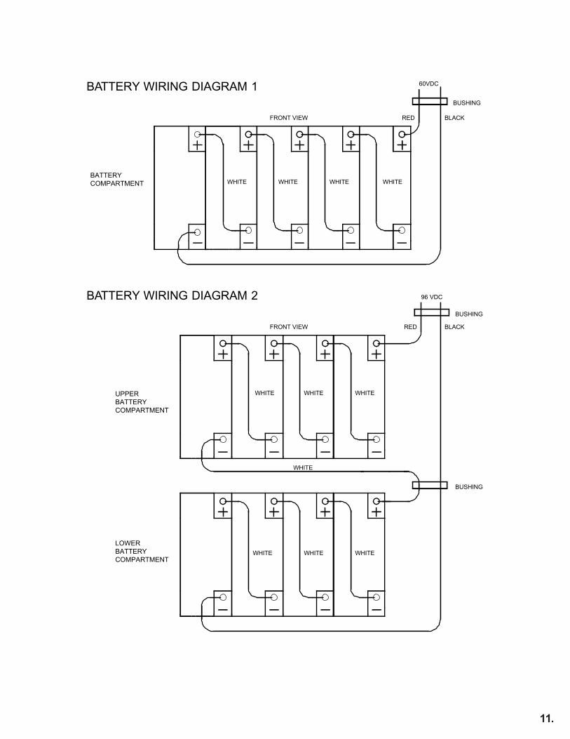
BATTERY WIRING DIAGRAM 1
BATTERY WIRING DIAGRAM 2
RED
RED
BLACK
BLACK
60VDC
96 VDC
FRONT VIEW
FRONT VIEW
BATTERYCOMPARTMENT
BUSHING
BUSHING
BUSHING
WHITE WHITE WHITE WHITE
WHITE WHITE WHITE
WHITE
WHITE WHITE WHITE
11.
UPPERBATTERYCOMPARTMENT
LOWERBATTERYCOMPARTMENT

106.3 Battery Voltage CheckUsing a digital volt-ohm meter, check for correct nominal battery voltage between DC Input NEG and POS wires. Voltage reading should be ±10% of system’s nominal 60Vdc for LPS-375, 96Vdc for LPS-600 operating voltage.
107. Final Installation ChecklistIMPORTANT: Before proceeding to the System Start-Up Procedure (Section 108) complete the Final Installation Checklist below.
1. Insure the LPS cabinet is securely fastened to a wall or other structure.
2. Insure that the input circuit breaker in the building service panel serving as the AC disconnect tothe LPS system is in the OFF position. Insure that both unit AC input breaker (CB-2) is in the offposition (if provided).
3. Check for proper ground connections in the LPS unit cabinet.
4. Check for any loose wiring connections in the LPS unit cabinet.
5. Check that correct nominal battery voltage (60Vdc for LPS-375, 96Vdc for LPS-600) is present inthe LPS unit between the bat-tery’s NEG and POS end terminals.
6. Verify AC Input Voltage Selector Jumpers are installed and in the proper position to accept the ACinput line voltage. system voltage configuration.CAUTION: Failure to install the Voltage Selector Jumpers will prevent system operation.Install-ing the Voltage Selector Jumpers in the position that does not match the AC inputline voltage will damage the unit, void the warranty and may cause an dangerous or unsafecondition.
108. System Start-Up ProcedureIMPORTANT: The LPS inverter system is a sophisticated electronic backup power supply.
Care must be taken to follow the steps below in their exact sequence. Failure to do so may result in possible equipment failure.
CAUTION: Familiarize yourself with the shut down procedure in Section 200.1 before proceed-ing with the LPS system Start Up.
1. Hold S-1 Pre-charge Switch in the on(up) position for 15 seconds then release.2. Place battery circuit breaker (CB-1) in the on position.3. Apply utility AC power to the system by turning the branch circuit breaker in the main power panel
to the ON position. Place AC input breaker CB-2 in the on position (if provided). Place AC outputbreakers CB-3 & CB-4 in the on position (if provided).
4. Observe the LED Status indicators and verify the following:A) AC ON indicator (red LED) is illuminated (indicates AC utility power is available to unit).B) CHG ON indicator (green LED) is illuminated (indicates battery is connected and charger isoperational).
5. Verify Normally-On fixtures or switched fixtures (where applicable) are illuminated (local fixtureswitch must be in ON position).
109. System TestMomentarily push TEST switch and verify the following:A) INV ON status indicator (yellow) illuminates (indicates inverter is operational).B) Normally-On, Normally-Off and Switched fixtures are illuminated (where applicable).
12.

110. System Self-Tests
Once the system is properly installed in accordance with the installation instructions, and AC power is supplied to the, the dual color (SDT STATUS) LED indicator will illuminate, followed by the amber (INV ON) LEDindicator. The dual color LED indicates the unit's status. A steady GREEN LED indicates normal service; A blinking GREEN/RED LED indicates the battery is charging; A blinking RED LED (in different combinations) indicates a service alert. Refer to the INDICATION chart in section 110.2 for details. During loss of normal utility power the dual color LED will not be illuminated. The AMBER (INV ON) LED indicator will be illuminated only during inverter operation initiated by the loss of utility power or during any manual or automatic self-test.
Do not touch components inside the unit. DC voltage is always present at the batteries and battery cables.Final Shut Down Procedure
110.1 Self-Test/Diagnostic FunctionsThe self-diagnostic function is factory preset and performs the following:
A) Continuous monitoring of battery, battery charger and connected loads.B) Self-testing and a (30) second discharge with a randomized start (per UL 924, Sec. 30.2), once every (30)
days, after normal utility power has been supplied for a minimum of (48) hours.C) Self-testing and a (30) minute discharge with a randomized start (per UL 924, Sec. 30.2), once every (180)
days, after normal utility power has been supplied for a minimum of (48) hours.D) Self-testing and a (90) minute discharge with a randomized start (per UL 924, Sec. 30.2), once every (365)
days, after normal utility power has been supplied for a minimum of (48) hours.
110.2 Self-Test/Diagnostic IndicationSDT Status LED Indicator Green steadyRED/GREEN blinkingGREEN blinkingOne blink RED/pauseTwo blinks RED/pauseFour blinks RED/pause
System StatusNormal ServiceHigh Charge enabledTest Mode enabledBattery Charger faultBattery faultLamp/Load fault
13.
200. Maintenance200.1 Safe Shut Down ProcedureCAUTION: To avoid possible equipment damage or personal injury, assume that there is AC voltage present inside the LPS inverter system unit any time AC input power or DC battery voltage is applied. The inverter is capable of providing output voltage from the batteries even when there is no AC input line voltage. When AC input voltage is present, the unit can provide output voltage even when the batteries are disconnected.
Do not touch components inside the unit. DC voltage is always present at the batteries and battery cables.
Final Shut Down Procedure1. Open the unit’s front access panel.2. Place unit battery circuit breaker (CB-1) in the off position. Place unit AC input breaker (CB-2) in
the off position (if provided). To make sure the unit will not supply output voltage.3. Place the AC Input circuit breaker at the service panel in the OFF position.
CAUTION: HAZARDOUS ENERGY IS STORED IN CAPACITORS INSIDE THE LPS UNIT.AFTER TURNING OFF SWITCHES, ALLOW 5 MINUTES FOR CAPACITORS TO DISCHARGEBEFORE ATTEMPTING ANY SERVICE PROCEDURES.
4. If the service technician does not need to access the inside of the unit, keep the unit’s front cover/door closed.
5. If the unit will be shut off for an extended period of time, recharge battery every 60 to 90 days.
CAUTION: The battery will be damaged and the warranty voided if not routinely recharged.
NOTE: To turn power back on, follow the “System Start-up Procedure” outlined in Section108. Be sure to complete all of the steps to assure the unit will operate properly.
200.2 Routine System MaintenanceThe LPS inverter system unit is designed to provide years of trouble-free operation. The unit does re-quire some routine attention to assure peak performance. The Manufacturer recommends a Preven-tative Maintenance check be performed by a qualified service technician at least every six months. The technician must observe important safety precautions while performing the following recommend-ed tasks:• Inspect and clean the unit interiors;• Inspect all batteries for leaks, case swelling or terminal corrosion;;• Perform an emergency operation test to check operation of all critical connected loads
200.3 Manual Routine Inverter TestsNFPA101 requires that Emergency Lighting Equipment be tested on a monthly basis for a period of at least 5 seconds, and a minimum of 90 minutes once a year. We strongly recommend these guidelines be followed to insure system readiness, and to prolong battery life. The LPS system was designed with a front panel test switch to facilitate monthly testing. Simply depress the button and hold to test the inverter at anytime. Once released, the LPS will revert back to standby operation. For annual 90-minute discharge or other prolonged tests, simply turn off the AC Input breaker at the service panel.
14.

200.4 Routine Battery Inspection and MaintenanceSealed Lead-Calcium BatteriesMaintenance-free cells are the most common type of battery used today in standby equipment. By design it is as maintenance free as a battery can be. It is recommended, however, that some simple steps be taken to increase system life and maximize reliability:
A) A quarterly visual check of the battery should be conducted to look for deformities in thebattery case, electrolyte leakage and/or terminal corrosion. Any batteries with these condi-tions are defective and should be replaced. Any corroded terminals found, regardless howslight, are to be cleaned at once to prevent system failure.
B) Once a year, all battery connections should be checked for tightness and cleaned and re-tightened as necessary.
200.5 Battery Replacement ProcedureWARNING: Always use the same quantity and type of battery as replacements.
Substituting batteries not supplied by the Manufacturer will void the UL listing of the system and may cause equipment failure. To ensure the superior performance of your LPS inverter system and tomaintain proper charger operation, replace spent batteries only with those having the same part num-ber, voltage and ampere-hour rating as the original batteries.
1. Follow the proper shut down procedure as described in Section 200.1.2. Carefully disconnect all battery wiring. Remove battery retention bracket(s).3. Remove the batteries from the cabinet.4. Install new batteries following the instructions outlined in Section 106.2.
200.6 Battery DisposalWARNINGS:
• Do not dispose of batteries in a fire, the batteries could explode.• Do not open or mutilate batteries.• Released electrolyte is highly toxic and harmful to the skin and eyes.
CAUTION: Batteries contain lead or cadmium, depending on model. Many state and local governments have regulations about used battery disposal. Please dispose of the batteries properly.
15.