Embed Size (px)
Citation preview
DESIGN AND DEVELOPMENT OF MICROSTRIP ARRAY ANTENNA AT
28 GHz
MUHAMAD AKLIFF BIN ABD RAHIM
This Report Is Submitted In Partial Fulfillment Of Requirements For The Bachelor Degree of Electronic Engineering (Telecommunication Electronic)
Fakulti Kejuruteraan Elektronik dan Kejuruteraan Komputer Universiti Teknikal Malaysia Melaka
JUNE 2016

v
DEDICATION
I dedicate this thesis to my beloved Father
Abd Rahim Bin Mohd
And
To the loving memory of my Mother
Noormah binti Hj. Hussien
You have successfully made me the person I am now
And
will always be remembered

vi
ACKNOWLEDGEMENT
First and foremost, I would like to extend my highest gratitude and thanks to my
project supervisor, Dr Imran bin Mohd Ibrahim for his valuable guidance, critics and
encouragement throughout the duration of my project. His willingness to spare time
and guide me throughout the project has contributed tremendously to my project. With
his continuous encouragement and support, this project finally had been presented.
Apart from that, I would like to express my deepest thanks and appreciation to
my beloved Father, family, my roommate and also my friends, for gracing me with
strength, wisdom, and confidence to complete this project.
ABSTRACT
5G technologies undergo a huge research to meet the fast growing wireless
communication whereby the high frequency is required to fulfil the high data capacity
demands. Mircostrip antenna is preferred due to its low profile, easy in feeding and array
configurations. The natural low gain of this antenna can be overcome by constructing
patch array antenna. In this project, configurations of patch array antennas are designed
by following the specification from ETSI EN 301 215 part 1-4, to investigate their
radiation patterns with different orientation ,excitation phase and gain at 28 GHz for 5G
application. Simulated Retur loss, VSWR and simulated radiation patterns are presented.
In future work, this project will be more focus on antenna array because to achived the
higher gain.
viii
ABSTRAK
Teknologi 5G telah dijalankan kajian secara menyeluruh untuk mengatasi
perkembangan yang pesat pada teknologi komunikasi tanpa wayar dimana frequensi
tinggi diperlukan untuk memenuhi sistem muatan data yang tinggi. Antena microstrip
dipilih disebabkan susuk rendah, dan kemudahan pengeluaran serta kemudahan
konfigurasi array. Keuntungan rendah pada antena ini boleh diatasi dengan konfigurasi
array. Di dalam project ini, konfigurasi tampal array antena direkabentuk, simulasi dan
fabrikasi untuk menganalisa mengikut spesifikasi daripada ETSI EN 301 215
bahagian 1-4 pada frekuensi 28 GHz. Pengukuran dan simulasi pekali pantulan,
VSWR telah dipaparkan adalah untuk mecapai spesifikasi yg ditentukan. Pada masa
hadapan, projek ini akan lebih fokus kepada antena tampal susunan.
ix
TABLE OF CONTENT
CHAPTER TITLE PAGE DECLARATION ii
DEDICATION v
ACKNOWLEDGEMENT vi
ABSTRACT vii
ABSTRAK viii
TABLE OF CONTENT ix
LIST OF TABLES xi
LIST OF FIGURES xiv
1 INTRODUCTION 1
1.1 Background study of 5G 1
1.2 Spectrum for 5G 3
1.3 Why do we need 5G? 4
1.4 Problem Statement 7
1.5 Objective of the Project 7
1.6 Scope of the Project 7
2 LITERATURE REVIEW 8
2.1 Millimeter-Wave Mobile Communications Microstrip
Antenna (28GHz or 38GHz)
8
2.2 Dense Dielectric Patch Array Antenna With Improved
Radiation Characteristics Using EBG Ground Structure
and Dielectric Superstrate
11
2.3 Single element microstrip patch antenna on Duroid 13
2.4 28 GHz High Efficiency Planar Array Antenna with Hybrid Feed Network
14
x
2.5 CPW fed Microstrip Antenna for Indoor Broadband
Wireless Communications
17
2.6 28-GHz Patch Antenna Arrays with PCB and LTCC
Substrates
18
2.7 28 GHz CRLH Antenna on Silicon Substrate 22
2.8 Microstrip Antenna for 5G Broadband Communications:
Overview of Design Issues
25
2.9 Corporate-Fed 2x2 Planar Microstrip Patch Sub-Array
for the 35 GHz Band
28
2.10 Design and Simulation of Double Ridged Horn (DRH)
Antenna Operating For UWB Applications
31
2.11 Multiband Smart Fractal Antenna Design for
Converged 5G Wireless Networks
35
2.12 Gain Enhancement In Microstrip Patch Antenna Using
The Multiple Substrate Layer Method
38
2.13 Performance Comparison between Rectangular and
Circular Patch Antenna Array
40
2.14 Design, Substrates Comparison and Fabrication of 8-
Element High Gain Microstrip Patch Antenna
42
2.15 Summarization researches for 28GHz Antenna 46
3 PROJECT METODOLOGY 49
3.1 Basic introduction 49
3.2 Feeding Technique 53
3.3 Polarization 56
3.4 Array Characteristic 57
3.5 Basic theory of Microstrip Antenna Operation 59
3.6 Flowchart of the Project Methodology 64
3.7 Gantt Chart of the Project Methodolgy 65
4 DESIGN AND SIMULATION OF ANTENNAS 66
4.1 Design Specification 66
4.2 The Rectangular Patch Dimensions 67
4.3 Single Patch Design 68
xi
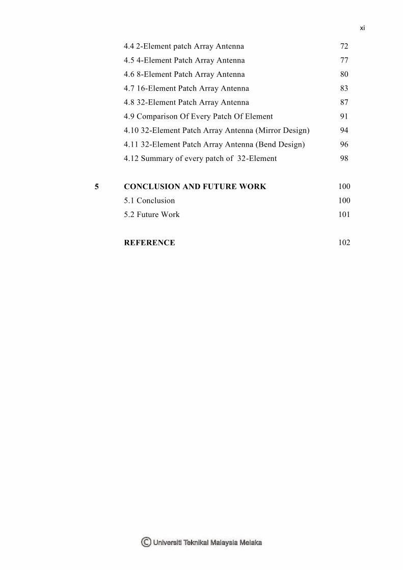
4.4 2-Element patch Array Antenna 72
4.5 4-Element Patch Array Antenna 77
4.6 8-Element Patch Array Antenna 80
4.7 16-Element Patch Array Antenna 83
4.8 32-Element Patch Array Antenna 87
4.9 Comparison Of Every Patch Of Element 91
4.10 32-Element Patch Array Antenna (Mirror Design) 94
4.11 32-Element Patch Array Antenna (Bend Design) 96
4.12 Summary of every patch of 32-Element 98
5 CONCLUSION AND FUTURE WORK 100
5.1 Conclusion 100
5.2 Future Work 101
REFERENCE 102
xii
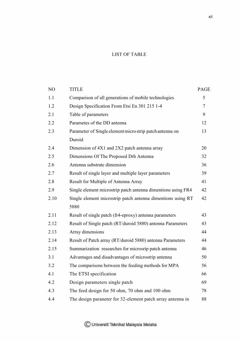
LIST OF TABLE
NO TITLE PAGE
1.1 Comparison of all generations of mobile technologies 5
1.2 Design Specification From Etsi En 301 215 1-4 7
2.1 Table of parameters 9
2.2 Parametes of the DD antenna 12
2.3 Parameter of Single element micro strip patch antenna on
Duroid
13
2.4 Dimension of 4X1 and 2X2 patch antenna array 20
2.5 Dimensions Of The Proposed Drh Antenna 32
2.6 Antenna substrate dimension 36
2.7 Result of single layer and multiple layer parameters 39
2.8 Result for Multiple of Antenna Array 41
2.9 Single element microstrip patch antenna dimentions using FR4 42
2.10 Single element microstrip patch antenna dimentions using RT
5880
42
2.11 Result of single patch (fr4-eproxy) antenna parameters 43
2.12 Result of Single patch (RT/duroid 5880) antenna Parameters 43
2.13 Array dimensions 44
2.14 Result of Patch array (RT/duroid 5880) antenna Parameters 44
2.15 Summarization researches for microsrip patch antenna 46
3.1 Advantages and disadvantages of microstrip antenna 50
3.2 The comparisons between the feeding methods for MPA 56
4.1 The ETSI specification 66
4.2 Design parameters single patch 69
4.3 The feed design for 50 ohm, 70 ohm and 100 ohm 78
4.4 The design paraneter for 32-element patch array antenna in 88
xiii
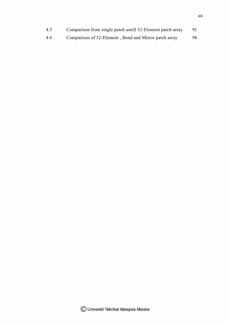
4.5 Comparison from single patch untill 32-Element patch array 91
4.6 Comparison of 32-Element , Bend and Mirror patch array 98
xiv
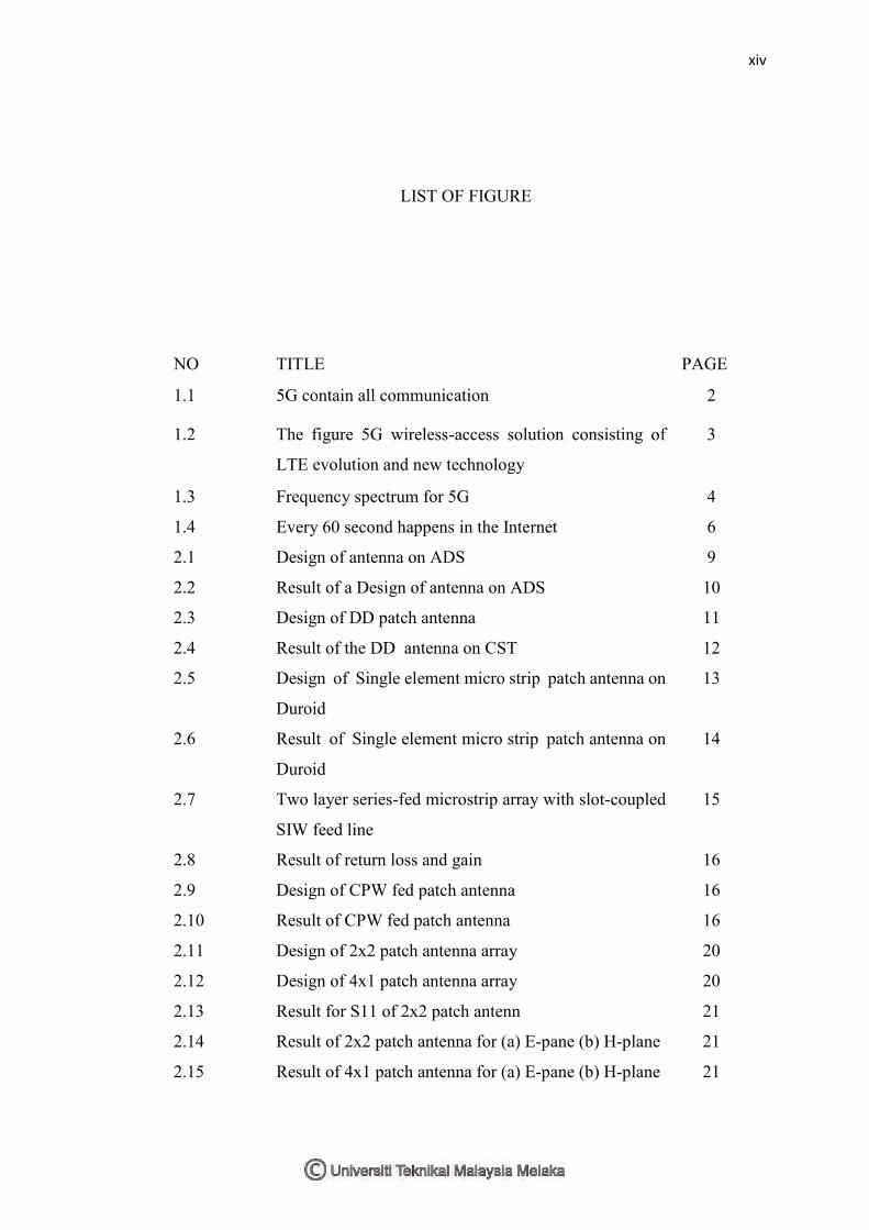
LIST OF FIGURE
NO TITLE PAGE
1.1 5G contain all communication 2
1.2 The figure 5G wireless-access solution consisting of
LTE evolution and new technology
3
1.3 Frequency spectrum for 5G 4
1.4 Every 60 second happens in the Internet 6
2.1 Design of antenna on ADS 9
2.2 Result of a Design of antenna on ADS 10
2.3 Design of DD patch antenna 11
2.4 Result of the DD antenna on CST 12
2.5 Design of Single element micro strip patch antenna on
Duroid
13
2.6 Result of Single element micro strip patch antenna on
Duroid
14
2.7 Two layer series-fed microstrip array with slot-coupled
SIW feed line
15
2.8 Result of return loss and gain 16
2.9 Design of CPW fed patch antenna 16
2.10 Result of CPW fed patch antenna 16
2.11 Design of 2x2 patch antenna array 20
2.12 Design of 4x1 patch antenna array 20
2.13 Result for S11 of 2x2 patch antenn 21
2.14 Result of 2x2 patch antenna for (a) E-pane (b) H-plane 21
2.15 Result of 4x1 patch antenna for (a) E-pane (b) H-plane 21
xv
2.16 CPW CRLH elementary cell that is used in antenna
construction
22
2.17 CPW CRLH elementary cell that is used in antenna
construction
23
2.18 Result of CPW CRLH elementary cell that is used in
antenna construction
24
2.19 Geometry of the patch antennas 26
2.20 Photo of the prototypes fabricated at 28 and 60GHz 26
2.21 Comparison of theoretical S11(f) between design
optimized without and with connector for patch at
28GHz
27
2.22 Comparison of theoretical S11(f) between design
optimized without and with connector for patch at
28GHz
27
2.23 Design of the sub-array 28
2.24 Design of the 4x4 array 29
2.25 Result of the 4x4 array 29
2.26 Design of the 8x8 array 30
2.27 Result of the 8x8 array 30
2.28 The designed antenna has been simulated using Ansoft
HFSS
32
2.29 Return Loss for designed horn antenna 33
2.30 Result for Simulated VSWR 33
2.31 Gain obtained for Horn antenna 34
2.32 Radiation Pattern 34
2.33 Multiband Antenna Structure 35
2.34 Return loss plot 37
2.35 VSWR Plot 37
2.36 Multiple Substrate Antenna proposed design 38
2.37 S11 Parameters glass substrate 39
2.38 S11 parameters for silicon/glass/silicon substrate 39
2.39 Design Layout of Four-Patches Rectangular Microstrip
Antenna Array and Four-Patches Circular
41
xvi
2.40 S11 response and VSWR 43
2.41 S11 response and VSWR 43
2.42 Array dimensions 44
2.43 S11 response and VSWR 45
3.1 Various shapes of microstrip patch antenna 50
3.2 Rectangular patch antenna 51
3.3 Cicular patch antenna 52
3.4 Annular resonator patch antenna 53
3.5 Geometry of Micro-Strip Feed line (a) directly feed (b)
Inset feed
54
3.6 Geometry of Coaxial Probe Feed microstrip patch
antenna (a) Top view (b) Side view
54
3.7 Geometry Aperture Coupled Feed microstrip patch
antenna (a) Top view (b) Side view
55
3.8 Geometry of proximity coupled feed microstrip patch
antenna (a) Top view (b) Side view
55
3.9 Illustrations of a 3-dB beam width 58
3.10 Physical and effective length of microstrip patch
antenna
60
3.11 Aperture Coupled Microstrip Patch Antenna 61
4.1 The front view of single patch antenna 68
4.2 The prespective view and back of single patch
antenna
69
4.3 Gain at 28GHz 69
4.4 a) Bandwidth b) Return loss 70
4.5 Return loss for width patch 3.6 to 4.5 71
4.6 Return loss for length gap 0.77mm to 0.9mm 71
4.7 The front view of 2x1 patch antenna 72
4.8 The calculation done by emtalk.com for 50 ohm feed 73
4.9 The calculation done by emtalk.com for 70 ohm feed 73
4.10 The calculation done by emtalk.com for 100 ohm
feed
73
xvii
4.11 The calculation done by emtalk.com for patch width
and length
74
4.12 Return loss for 2-Element patch antenna 75
4.13 Voltage standing wave ratio(VSWR) for 2-Element
patch antenna
75
4.14 Gain for 2-Element patch antenna in 3D model 76
4.15 Farfield array for 2-Element patch antenna in polar
model (phi=90)
76
4.16 The front view of 2x2 patch antenna 77
4.17 The s-parameter of 2x2 patch antenna 78
4.18 The voltage standing wave ratio(VSWR) of 2x2
patch antenna
79
4.19 Farfield pattern of 2x2 patch antenna 79
4.20 4.20 Farfield array for 4-Element patch antenna in
polar model
80
4.21 The front view of 4x2 patch antenna 80
4.22 The Return loss for 8-Element patch Array antenna 81
4.23 The VSWR for 8-Element patch array antenna 82
4.24 The Farfield result for 8-Element patch array
antenna
82
4.25 The Farfield result (polar) for 8-Element patch array
antenna
83
4.26 The front view of 4x4 patch antenna 84
4.27 Return loss of 4x4 patch antenna 84
4.28 VSWR for 4x4 patch antenna 85
4.29 Farfield result (3D) of 4x4 patch antenna 86
4.30 Farfield result (polar) of 4x4 patch antenna 86
4.31 The front view of 4x8 patch antenna 87
4.32 The Return loss for 32-Element patch array antenna 88
4.33 The VSWR for 32-Element patch array antenna 89
4.34 The Gain (3D) for 32-Element patch array antenna 90
4.35 The Directivity (polar) for phi 0 and phi 90 for 32-
Element
90
xviii
4.36 The Directivity (polar) for phi 0 and phi 90 for 32-
Element
91
4.37 Comparison of return loss from single patch untill
32-Element
92
4.38 Comparison of radiation pattern (polar) from single
patch untill 32-Element
93
4.39 Design of 32-Element patch array antenna (Mirror) 94
4.40 Return loss for 32-Element patch array antenna
(mirror)
95
4.41 Radiation pattern (3D) for 32-Element patch array
antenna (mirror) design
95
4.42 Radiation pattern (polar) for 32-Element patch array
antenna
96
4.43 Design of 32-Element Patch Array Antenna (Bend
Design)
96
4.44 Return loss for 32-Element Patch Array Antenna 97
4.45 Radiation pattern for 32-Element Patch Array
Antenna (Bend)
98
4.46 Retun loss for 32-Element , Bend and Mirror patch
array
99
4.47 Radiation pattern for 32-Element , Bend and Mirror
patch array
99
1
CHAPTER 1
INTRODUCTION
1.0 Introduction
In this project we are designing and develop the antenna of 28 GHz Mircostrip
Antenna Array. The problem statement of the project, is the compact of the previous
service provider. Other than that, there are so many type Antenna but to fiind the
cheaper antenna that follow the specification are hard to had . The main objective
of the antenna is to understand the 5G oprate on 28 GHz antenna, to design the
antenna and fabricate the design on selected substrate. The scope of the project, is
to design antenna on many type on difference type of substrate to see the result of
the parameters. This project will be divide into 2 categories that is simulation and
hardware. The design will undergo by CST. The expectation of the project is, the
operating frequency (28 GHz) with specification can be achieved in the simulation
and also on the hardware.
1.1 Background study of 5G
5G is the next step in the evolution of mobile communication. It will be
a key component of the Networked Society and will help realize the vision of
essentially unlimited access to information and sharing of data anywhere and
2
anytime for anyone and anything [1]. 5G will therefore not only be about
mobile connectivity for people. Rather, the aim of 5G is to provide ubiquitous
connectivity for any kind of device and any kind of application that may benefit
from being connected.
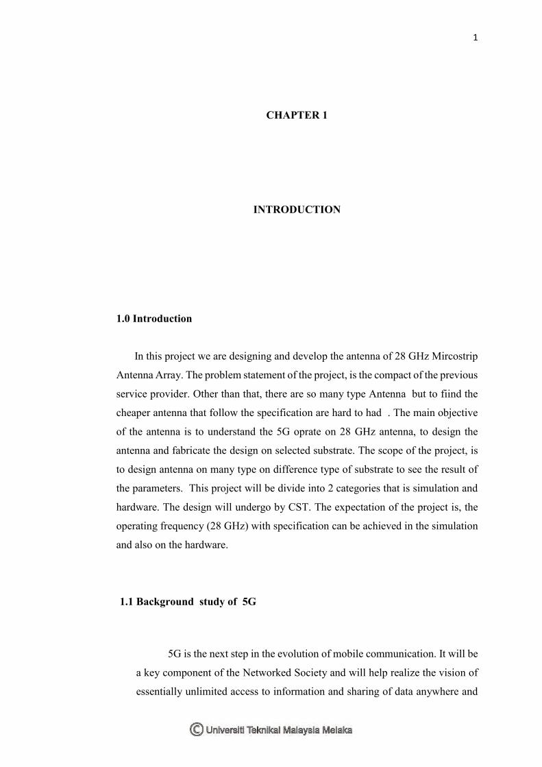
Mobile broadband will continue to be important and will drive the need
for higher system capacity and higher data rates. But 5G will also provide
wireless connectivity for a wide range of new applications and use cases,
including wearables, smart homes, traffic safety/control, and critical
infrastructure and industry applications, as well as for very-high-speed media
delivery.
Figure 1.1 5G contain all communication
In contrast to earlier generations, 5G wireless access should not be seen
as a specific radio-access technology. Rather, it is an overall wireless-access
solution addressing the demands and requirements of mobile communication
beyond 2020.
LTE will continue to develop in a backwards-compatible way and will
be an important part of the 5G wireless-access solution for frequency bands
below 6GHz. Around 2020, there will be massive deployments of LTE
providing services to an enormous number of devices in these bands. For
operators with limited spectrum resources, the possibility to introduce 5G
capabilities in a backwards-compatible way, thereby allowing legacy devices
3
to continue to be served on the same carrier, is highly beneficial and, in some
cases, even vital.
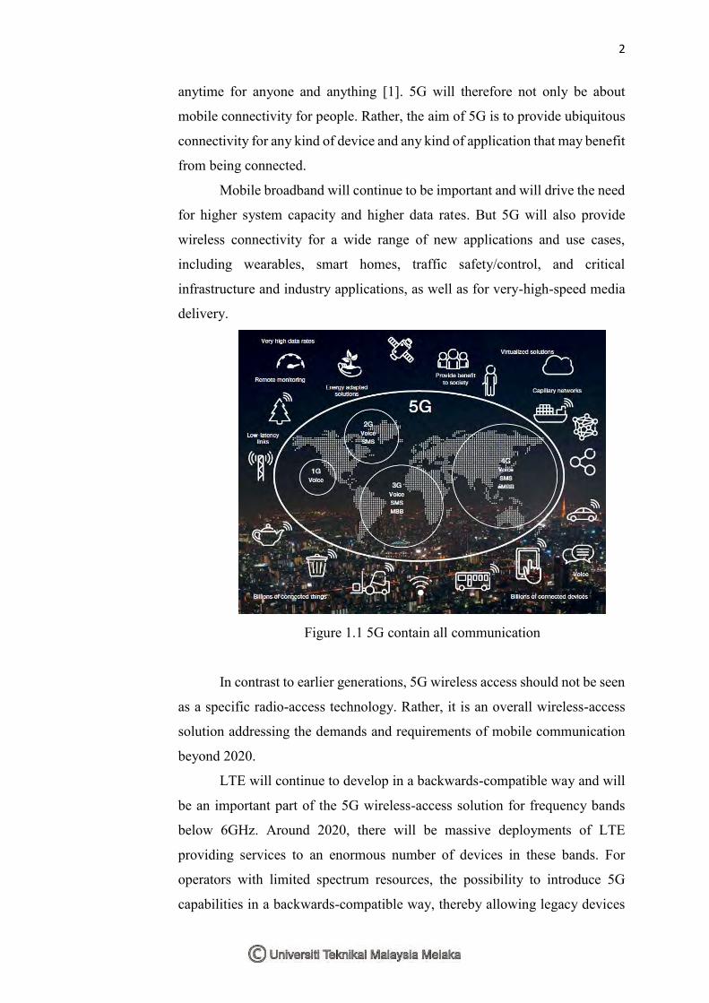
In parallel, new radio-access technology (RAT) without backwards-
compatibility requirements will emerge, at least initially targeting new
spectrum for which backwards compatibility is not relevant. In the longer-term
perspective, the new non-backwards-compatible technology may also migrate
into existing spectrum
Figure 1.2 The figure 5G wireless-access solution consisting of LTE
evolution and new technology
Although the overall 5G wireless-access solution will consist of different
components, including the evolution of LTE as well as new technology, the different
components should be highly integrated with the possibility for tight interworking
between them. This includes dual-connectivity between LTE operating on lower
frequencies and new technology on higher frequencies. It should also include the
possibility for user-plane aggregation, that is, joint delivery of data via both LTE and
a new RAT
.
1.2 Spectrum for 5G
In order to further extend traffic capacity and to enable the transmission
bandwidths needed to support very high data rates, 5G will extend the range of
frequencies used for mobile communication. This includes new spectrum below
6GHz, expected to be allocated for mobile communication at the World Radio
Conference (WRC) 2015, as well as spectrum in higher frequency bands, expected to
be on the agenda for WRC 2019.
4
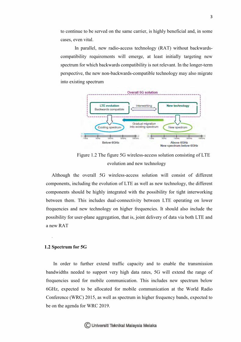
It is still unclear what spectrum in higher frequency bands will be made available
for mobile communication, and the entire frequency range up to approximately
100GHz is considered at this stage. The lower part of this frequency range, below
30GHz, is preferred from the point of view of propagation properties. At the same
time, very large amounts of spectrum and the possibility of very wide transmission
bandwidths, in the order of 1GHz or even more, will only be available in frequency
bands above 30GHz.
Thus, spectrum relevant for 5G wireless access ranges from below 1GHz up to in
the order of 100GHz, as Figure 2 shows.
Figure 1.3 Frequency spectrum for 5G
It is important to understand that high frequencies, especially those above 10GHz,
can only serve as a complement, providing additional system capacity and very wide
transmission bandwidths for extreme data rates in dense deployments. Lower
frequencies will remain the backbone for mobile-communication networks in the 5G
era, providing ubiquitous wide-area connectivity.
1.3 Why do we need 5G?
One of the main benefits of 5G technology over 4G will not be its speed of delivery
– which admittedly could be between 10Gbps and 100Gbps – but the latency. At
present, 4G is capable of between 40ms and 60ms, which is low-latency but not enough
to provide real-time response. Multiplayer gaming, for example, requires a lower
latency than that to ensure that when you hit a button, the remote server responds
instantly. Another example was given to us by EE’s Sutton, who said that 5G’s
prospective ultra-low-latency could range between 1ms and 10ms. This would allow,
he said, a spectator in a football stadium to watch a live stream of an alternative camera
5
angle of the action that matches what is going on the pitch ahead with no perceivable
delay.
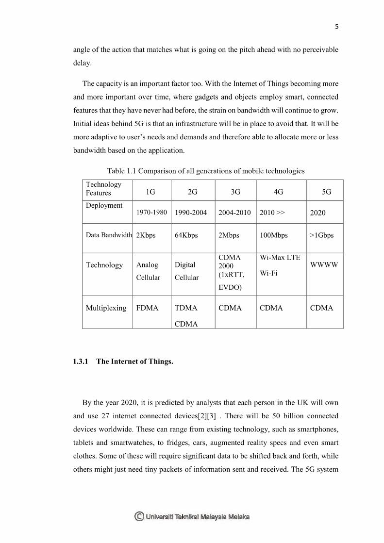
The capacity is an important factor too. With the Internet of Things becoming more
and more important over time, where gadgets and objects employ smart, connected
features that they have never had before, the strain on bandwidth will continue to grow.
Initial ideas behind 5G is that an infrastructure will be in place to avoid that. It will be
more adaptive to user’s needs and demands and therefore able to allocate more or less
bandwidth based on the application.
Table 1.1 Comparison of all generations of mobile technologies
Technology Features 1G 2G 3G 4G 5G
Deployment 1970-1980 1990-2004 2004-2010 2010 >> 2020
Data Bandwidth 2Kbps 64Kbps 2Mbps 100Mbps >1Gbps
Technology Analog
Cellular Digital
Cellular
CDMA 2000 (1xRTT,
EVDO)
Wi-Max LTE
Wi-Fi WWWW
Multiplexing FDMA TDMA
CDMA
CDMA CDMA CDMA
1.3.1 The Internet of Things.
By the year 2020, it is predicted by analysts that each person in the UK will own
and use 27 internet connected devices[2][3] . There will be 50 billion connected
devices worldwide. These can range from existing technology, such as smartphones,
tablets and smartwatches, to fridges, cars, augmented reality specs and even smart
clothes. Some of these will require significant data to be shifted back and forth, while
others might just need tiny packets of information sent and received. The 5G system
6
itself will understand and recognise this and allocate bandwidth respectively, thereby
not putting unnecessary strain on individual connection points.
The work has already begun for 4G implementation, but will become even more
vital to a 5G future. As part of a “heterogeneous network", the points, or cells, will be
used for LTE-A and the technology will be increased and refined to adapt to 5G too.
Cells will automatically talk to each device to provide the best and most efficient
service no matter where the user is. Larger cells will be used in the same way as they
are now, with broad coverage, but urban areas, for example, will also be covered by
multiple smaller cells, fitted in lampposts, on the roofs of shops and homes, and even
inside bricks in new buildings. Each of these will ensure that the connection will be
regulated and seemingly standard across the board.
Algorithms will even know how fast a device is travelling, so can adapt to which
cell it is connected to. For example, a connected car might require connection to a
macro-cell, such as a large network mast, in order to maintain its connection without
having to re-establish continuously over distance, while a person’s smartphone can
connect to smaller cells with less area coverage as the next cell can be picked up easily
and automatically in enough time to prevent the user noticing.
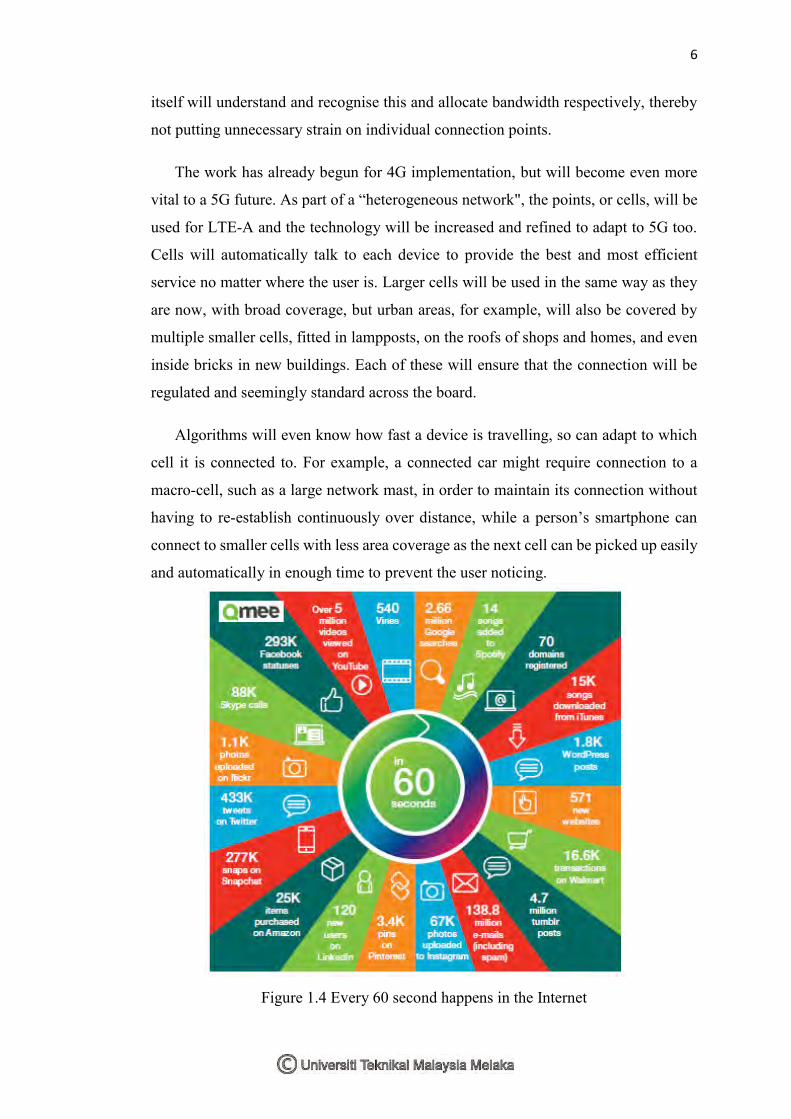
Figure 1.4 Every 60 second happens in the Internet