Embed Size (px)
Citation preview
Mueller Industries, Inc. 1
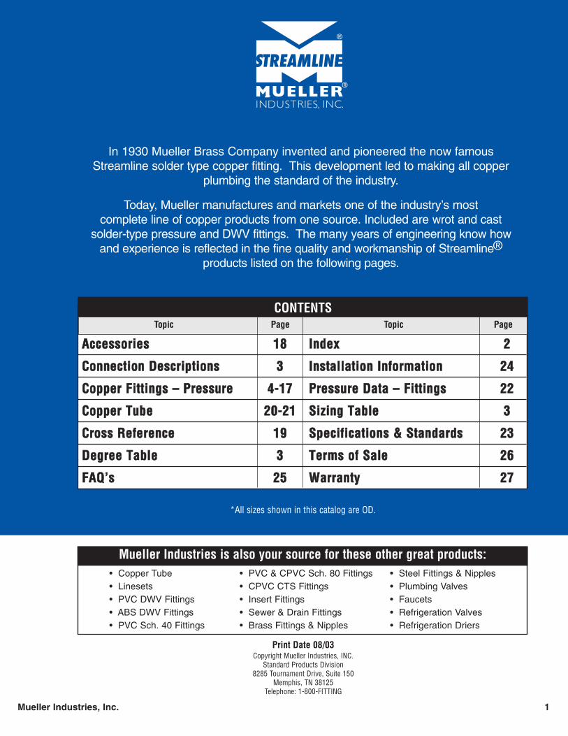
In 1930 Mueller Brass Company invented and pioneered the now famousStreamline solder type copper fitting. This development led to making all copper
plumbing the standard of the industry.
Today, Mueller manufactures and markets one of the industry’s most complete line of copper products from one source. Included are wrot and cast
solder-type pressure and DWV fittings. The many years of engineering know howand experience is reflected in the fine quality and workmanship of Streamline®
products listed on the following pages.
Topic Page Topic Page
CONTENTS
AAcccceessssoorriieess 1188
CCoonnnneeccttiioonn DDeessccrriippttiioonnss 33
CCooppppeerr FFiittttiinnggss –– PPrreessssuurree 44--1177
CCooppppeerr TTuubbee 2200--2211
CCrroossss RReeffeerreennccee 1199
DDeeggrreeee TTaabbllee 33
FFAAQQ’’ss 2255
IInnddeexx 22
IInnssttaallllaattiioonn IInnffoorrmmaattiioonn 2244
PPrreessssuurree DDaattaa –– FFiittttiinnggss 2222
SSiizziinngg TTaabbllee 33
SSppeecciiffiiccaattiioonnss && SSttaannddaarrddss 2233
TTeerrmmss ooff SSaallee 2266
WWaarrrraannttyy 2277
Mueller Industries is also your source for these other great products:• Copper Tube • PVC & CPVC Sch. 80 Fittings • Steel Fittings & Nipples• Linesets • CPVC CTS Fittings • Plumbing Valves• PVC DWV Fittings • Insert Fittings • Faucets• ABS DWV Fittings • Sewer & Drain Fittings • Refrigeration Valves• PVC Sch. 40 Fittings • Brass Fittings & Nipples • Refrigeration Driers
Print Date 08/03Copyright Mueller Industries, INC.
Standard Products Division8285 Tournament Drive, Suite 150
Memphis, TN 38125Telephone: 1-800-FITTING
*All sizes shown in this catalog are OD.
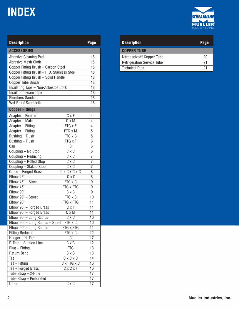
INDEX
2 Mueller Industries, Inc.
DDeessccrriippttiioonn PPaaggee
AACCCCEESSSSOORRIIEESS
Abrasive Cleaning Pad 18Abrasive Mesh Cloth 18Copper Fitting Brush – Carbon Steel 18Copper Fitting Brush – H.D. Stainless Steel 18Copper Fitting Brush – Solid Handle 18Copper Tube Brush 18Insulating Tape – Non-Asbestos Cork 18Insulation Foam Tape 18Plumbers Sandcloth 18Wet Proof Sandcloth 18
CCooppppeerr FFiittttiinnggss
Adapter – Female C x F 4Adapter – Male C x M 4Adapter – Fitting FTG x F 4Adapter – Fitting FTG x M 5Bushing – Flush FTG x C 5Bushing – Flush FTG x F 6Cap C 6Coupling – No Stop C x C 6Coupling – Reducing C x C 7Coupling – Rolled Stop C x C 7Coupling – Staked Stop C x C 7Cross – Forged Brass C x C x C x C 8Elbow 45˚ C x C 8Elbow 45˚ – Street FTG x C 9Elbow 45˚ FTG x FTG 9Elbow 90˚ C x C 9Elbow 90˚ – Street FTG x C 10Elbow 90˚ FTG x FTG 11Elbow 90˚ – Forged Brass C x F 11Elbow 90˚ – Forged Brass C x M 11Elbow 90˚ – Long Radius C x C 10Elbow 90˚ – Long Radius – Street FTG x C 10Elbow 90˚ – Long Radius FTG x FTG 11Fitting Reducer FTG x C 12Hanger – Hi-Ear C 17P-Trap – Suction Line C x C 12Plug – Fitting FTG 13Return Bend C x C 13Tee C x C x C 14Tee – Fitting C x FTG x C 16Tee – Forged Brass C x C x F 16Tube Strap – 2-Hole 17Tube Strap – Perforated 17Union C x C 17
DDeessccrriippttiioonn PPaaggee
CCOOPPPPEERR TTUUBBEE
Nitrogenized® Copper Tube 20Refrigeration Service Tube 21Technical Data 21
GENERAL INFORMATION
Mueller Industries, Inc. 3
Degree Bend
Symbol Name Description
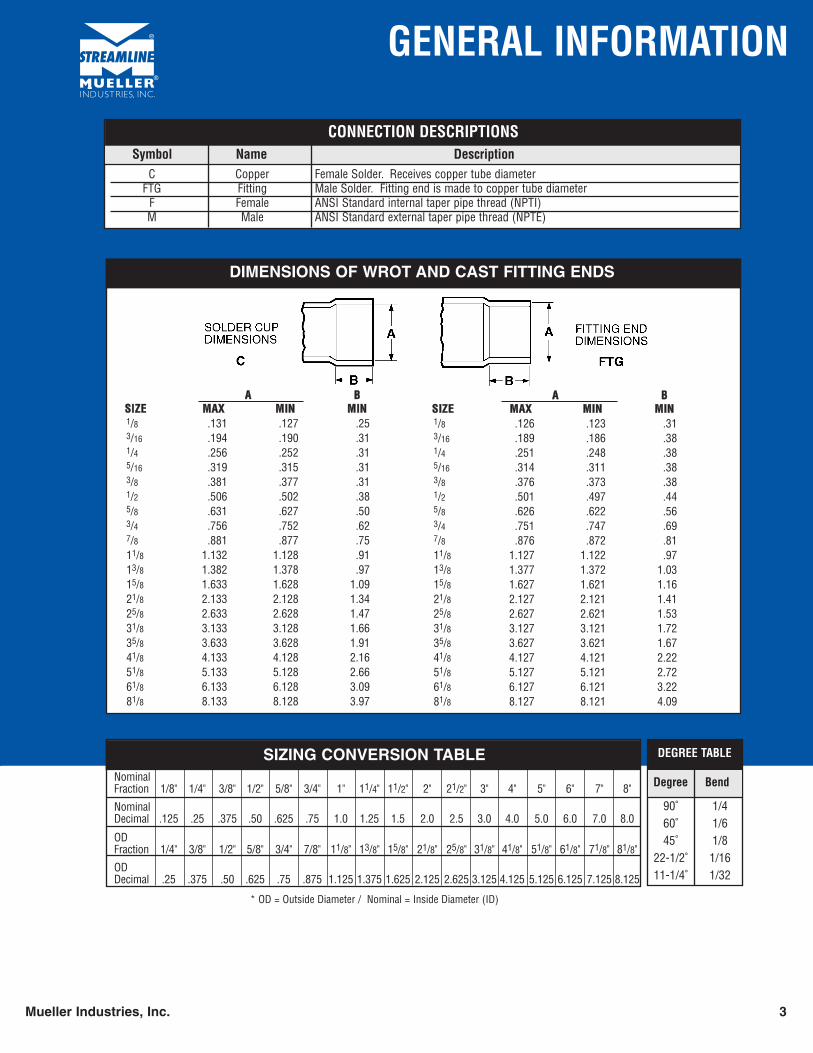
CONNECTION DESCRIPTIONS
C Copper Female Solder. Receives copper tube diameterFTG Fitting Male Solder. Fitting end is made to copper tube diameter
F Female ANSI Standard internal taper pipe thread (NPTI)M Male ANSI Standard external taper pipe thread (NPTE)
* OD = Outside Diameter / Nominal = Inside Diameter (ID)
DEGREE TABLE
90˚ 1/460˚ 1/645˚ 1/8
22-1/2˚ 1/1611-1/4˚ 1/32
DIMENSIONS OF WROT AND CAST FITTING ENDS
AA BBSSIIZZEE MMAAXX MMIINN MMIINN1/8 .131 .127 .253/16 .194 .190 .311/4 .256 .252 .315/16 .319 .315 .313/8 .381 .377 .311/2 .506 .502 .385/8 .631 .627 .503/4 .756 .752 .627/8 .881 .877 .7511/8 1.132 1.128 .9113/8 1.382 1.378 .9715/8 1.633 1.628 1.0921/8 2.133 2.128 1.3425/8 2.633 2.628 1.4731/8 3.133 3.128 1.6635/8 3.633 3.628 1.9141/8 4.133 4.128 2.1651/8 5.133 5.128 2.6661/8 6.133 6.128 3.0981/8 8.133 8.128 3.97
AA BBSSIIZZEE MMAAXX MMIINN MMIINN1/8 .126 .123 .313/16 .189 .186 .381/4 .251 .248 .385/16 .314 .311 .383/8 .376 .373 .381/2 .501 .497 .445/8 .626 .622 .563/4 .751 .747 .697/8 .876 .872 .8111/8 1.127 1.122 .9713/8 1.377 1.372 1.0315/8 1.627 1.621 1.1621/8 2.127 2.121 1.4125/8 2.627 2.621 1.5331/8 3.127 3.121 1.7235/8 3.627 3.621 1.6741/8 4.127 4.121 2.2251/8 5.127 5.121 2.7261/8 6.127 6.121 3.2281/8 8.127 8.121 4.09
SIZING CONVERSION TABLENominalFraction 1/8" 1/4" 3/8" 1/2" 5/8" 3/4" 1" 11/4" 11/2" 2" 21/2" 3" 4" 5" 6" 7" 8"
NominalDecimal .125 .25 .375 .50 .625 .75 1.0 1.25 1.5 2.0 2.5 3.0 4.0 5.0 6.0 7.0 8.0
OD Fraction 1/4" 3/8" 1/2" 5/8" 3/4" 7/8" 11/8" 13/8" 15/8" 21/8" 25/8" 31/8" 41/8" 51/8" 61/8" 71/8" 81/8"
ODDecimal .25 .375 .50 .625 .75 .875 1.125 1.375 1.625 2.125 2.625 3.125 4.125 5.125 6.125 7.125 8.125

SOLDER JOINT PRESSURE FITTINGSADAPTERS
4 * Brass Mueller Industries, Inc.All sizes are O.D.
Size Part Box Master Approx. Dimensions1 2 3 Number Qty. Qty. Net. Wt. A B C
MUELLER STYLEWC-402
CONNECTIONC x F
ELKHART STYLE103
NIBCO STYLE9603
ADAPTER – FEMALE
1/4 x 1/2 W 01204 100 300 .11 15/64
x 3/8 W 01205 100 700 .06 5/8x 1/4 W 01206 100 900 .04 21/32
x 1/8 W 01207 100 1,500 .03 9/16
3/8 x 3/8 W 01214 50 1,000 .05 21/32
x 1/4 W 01215 50 750 .04 5/8x 1/8 W 01216 100 1,500 .03 17/32
1/2 x 3/4 W 01223 50 300 .13 13/16
x 1/2 W 01224 50 500 .10 1x 3/8 W 01225 50 750 .06 53/64
x 1/4 W 01226 50 750 .05 19/32
5/8 x 3/4 W 01230 25 250 .15 1 3/64
x 1/2 W 01231 50 500 .10 27/32
x 3/8 W 01232 50 500 .07 49/64
x 1/4 W 01233 50 500 .05 1/23/4 x 3/4 W 01238 50 500 .14 57/64
x 1/2 W 01239 50 500 .09 29/32
7/8 x 1 W 01245 25 250 .24 1 5/32
x 3/4 W 01246 25 250 .14 27/32
x 1/2 W 01247 25 250 .11 111/8 x 11/4 W 01261 10 100 .28 1 7/32
x 1 W 01263 25 250 .24 31/32
x 3/4 W 01264 25 250 .22 13/16
x 1/2 W 01265 20 200 .29 23/32
13/8 x 11/2 W 01270 10 100 .52 113/32
x 11/4 W 01271 10 100 .43 1 7/32
x 1 W 01272 10 100 .33 115/8 x 2 W 01278 – 60 .72 1 7/32
x 11/2 W 01279 10 100 .58 1 1/4x 11/4 W 01280 5 50 .42 29/32
21/8 x 2 W 01287 – 50 .74 15/16
x 11/2 W 01288 5 50 .74 1 3/16
25/8 x 21/2 W 01296 – 25 1.19 1 3/16
31/8 x 3 W 01297 – 15 1.83 1 5/16
Size Part Box Master Approx. Dimensions1 2 3 Number Qty. Qty. Net. Wt. A B C
MUELLER STYLEWC-405
CONNECTIONFTG x F
ELKHART STYLE103-2
NIBCO STYLE9603-2
ADAPTER – FITTING
3/8 x 3/8 W 01514 50 750 .06 1 9/32
1/2 x 1/2 W 01524 50 350 .11 115/32
x 3/8 W 01525 50 750 .05 119/64
x 1/4 W 01526 50 750 .06 1 1/85/8 x 1/2 W 01531 50 450 .11 1 1/2
x 3/8 W 01532 50 750 .07 119/64
7/8 x 3/4 W 01546 25 250 .19 145/64
x 1/2 W 01547 50 500 .11 111/16
11/8 x 1 W 01563 25 250 .25 2 5/64
x 3/4 W 01564 25 250 .17 149/64
13/8 x 11/4 W 01571 10 100 .43 2 7/32
15/8 x 11/2 W 01579 10 100 .55 215/32
21/8 x 2 W 01587 – 50 .68 213/32
25/8 x 21/2 W 01596 – 25 1.21 253/64
Size Part Box Master Approx. Dimensions1 2 3 Number Qty. Qty. Net. Wt. A B C
MUELLER STYLEWC-401
CONNECTIONC x M
ELKHART STYLE104
NIBCO STYLE9604
ADAPTER – MALE
1/4 x 3/8 W 01105 50 1000 .04 3/4x 1/4 W 01106 50 1,200 .03 49/64
x 1/8 W 01107 100 2,400 .02 27/645/16 x 1/8 W 01109* 50 800 .07 27/32
x 1/4 W 01110* 50 1,200 .03 5/83/8 x 1/2 W 01113 50 500 .09 1
x 3/8 W 01114 50 1,000 .06 63/64
x 1/4 W 01115 50 1,200 .03 21/32
x 1/8 W 01116 50 1,000 .01 17/321/2 x 3/4 W 01123 25 250 .17 1 7/64
x 1/2 W 01124 50 500 .09 13/16
x 3/8 W 01125 50 500 .06 21/32
x 1/4 W 01126 50 750 .06 7/85/8 x 1 W 01129 15 150 .28 129/64
x 3/4 W 01130 25 250 .16 15/16
x 1/2 W 01131 50 500 .08 13/16
Continued on next page.
SOLDER JOINT PRESSURE FITTINGSADAPTERS / BUSHINGS
Mueller Industries, Inc. All sizes are O.D. 5
Size Part Box Master Approx. Dimensions1 2 3 Number Qty. Qty. Net. Wt. A B C
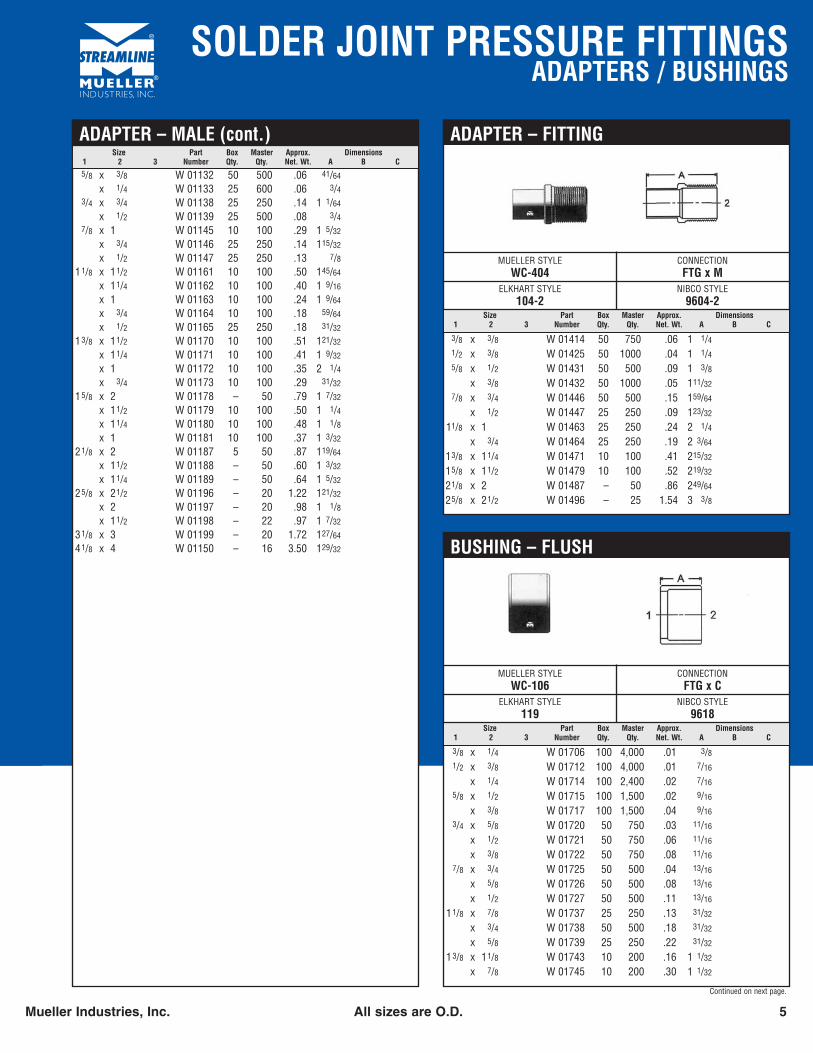
ADAPTER – MALE (cont.)
5/8 x 3/8 W 01132 50 500 .06 41/64
x 1/4 W 01133 25 600 .06 3/43/4 x 3/4 W 01138 25 250 .14 1 1/64
x 1/2 W 01139 25 500 .08 3/47/8 x 1 W 01145 10 100 .29 1 5/32
x 3/4 W 01146 25 250 .14 115/32
x 1/2 W 01147 25 250 .13 7/811/8 x 11/2 W 01161 10 100 .50 145/64
x 11/4 W 01162 10 100 .40 1 9/16
x 1 W 01163 10 100 .24 1 9/64
x 3/4 W 01164 10 100 .18 59/64
x 1/2 W 01165 25 250 .18 31/32
13/8 x 11/2 W 01170 10 100 .51 121/32
x 11/4 W 01171 10 100 .41 1 9/32
x 1 W 01172 10 100 .35 2 1/4x 3/4 W 01173 10 100 .29 31/32
15/8 x 2 W 01178 – 50 .79 1 7/32
x 11/2 W 01179 10 100 .50 1 1/4x 11/4 W 01180 10 100 .48 1 1/8x 1 W 01181 10 100 .37 1 3/32
21/8 x 2 W 01187 5 50 .87 119/64
x 11/2 W 01188 – 50 .60 1 3/32
x 11/4 W 01189 – 50 .64 1 5/32
25/8 x 21/2 W 01196 – 20 1.22 121/32
x 2 W 01197 – 20 .98 1 1/8x 11/2 W 01198 – 22 .97 1 7/32
31/8 x 3 W 01199 – 20 1.72 127/64
41/8 x 4 W 01150 – 16 3.50 129/32
Size Part Box Master Approx. Dimensions1 2 3 Number Qty. Qty. Net. Wt. A B C
MUELLER STYLEWC-404
CONNECTIONFTG x M
ELKHART STYLE104-2
NIBCO STYLE9604-2
ADAPTER – FITTING
3/8 x 3/8 W 01414 50 750 .06 1 1/41/2 x 3/8 W 01425 50 1000 .04 1 1/45/8 x 1/2 W 01431 50 500 .09 1 3/8
x 3/8 W 01432 50 1000 .05 111/32
7/8 x 3/4 W 01446 50 500 .15 159/64
x 1/2 W 01447 25 250 .09 123/32
11/8 x 1 W 01463 25 250 .24 2 1/4x 3/4 W 01464 25 250 .19 2 3/64
13/8 x 11/4 W 01471 10 100 .41 215/32
15/8 x 11/2 W 01479 10 100 .52 219/32
21/8 x 2 W 01487 – 50 .86 249/64
25/8 x 21/2 W 01496 – 25 1.54 3 3/8
Size Part Box Master Approx. Dimensions1 2 3 Number Qty. Qty. Net. Wt. A B C
MUELLER STYLEWC-106
CONNECTIONFTG x C
ELKHART STYLE119
NIBCO STYLE9618
BUSHING – FLUSH
3/8 x 1/4 W 01706 100 4,000 .01 3/81/2 x 3/8 W 01712 100 4,000 .01 7/16
x 1/4 W 01714 100 2,400 .02 7/16
5/8 x 1/2 W 01715 100 1,500 .02 9/16
x 3/8 W 01717 100 1,500 .04 9/16
3/4 x 5/8 W 01720 50 750 .03 11/16
x 1/2 W 01721 50 750 .06 11/16
x 3/8 W 01722 50 750 .08 11/16
7/8 x 3/4 W 01725 50 500 .04 13/16
x 5/8 W 01726 50 500 .08 13/16
x 1/2 W 01727 50 500 .11 13/16
11/8 x 7/8 W 01737 25 250 .13 31/32
x 3/4 W 01738 50 500 .18 31/32
x 5/8 W 01739 25 250 .22 31/32
13/8 x 11/8 W 01743 10 200 .16 1 1/32
x 7/8 W 01745 10 200 .30 1 1/32
Continued on next page.
SOLDER JOINT PRESSURE FITTINGSBUSHINGS / CAPS / COUPLINGS
6 * Brass Mueller Industries, Inc.All sizes are O.D.
Size Part Box Master Approx. Dimensions1 2 3 Number Qty. Qty. Net. Wt. A B C
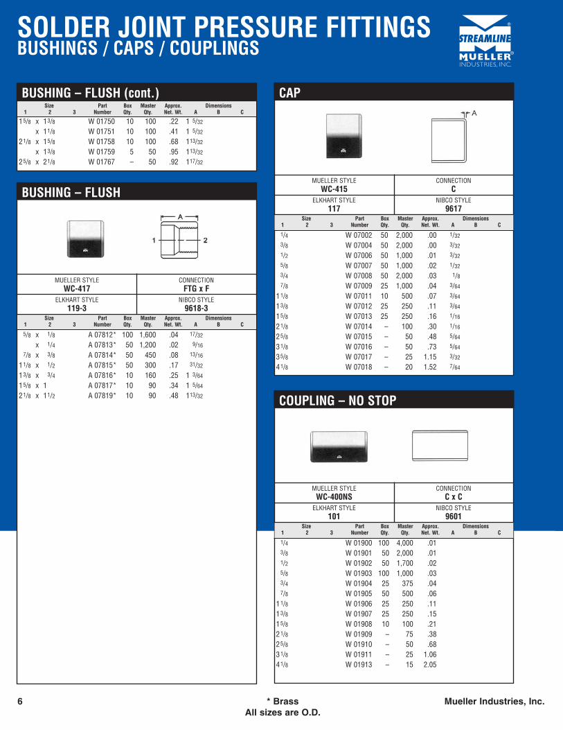
BUSHING – FLUSH (cont.)
15/8 x 13/8 W 01750 10 100 .22 1 5/32
x 11/8 W 01751 10 100 .41 1 5/32
21/8 x 15/8 W 01758 10 100 .68 113/32
x 13/8 W 01759 5 50 .95 113/32
25/8 x 21/8 W 01767 – 50 .92 117/32
Size Part Box Master Approx. Dimensions1 2 3 Number Qty. Qty. Net. Wt. A B C
MUELLER STYLEWC-417
CONNECTIONFTG x F
ELKHART STYLE119-3
NIBCO STYLE9618-3
BUSHING – FLUSH
5/8 x 1/8 A 07812* 100 1,600 .04 17/32
x 1/4 A 07813* 50 1,200 .02 9/16
7/8 x 3/8 A 07814* 50 450 .08 13/16
11/8 x 1/2 A 07815* 50 300 .17 31/32
13/8 x 3/4 A 07816* 10 160 .25 1 3/64
15/8 x 1 A 07817* 10 90 .34 1 5/64
21/8 x 11/2 A 07819* 10 90 .48 113/32
Size Part Box Master Approx. Dimensions1 2 3 Number Qty. Qty. Net. Wt. A B C
MUELLER STYLEWC-415
CONNECTIONC
ELKHART STYLE117
NIBCO STYLE9617
CAP
1/4 W 07002 50 2,000 .00 1/32
3/8 W 07004 50 2,000 .00 3/32
1/2 W 07006 50 1,000 .01 3/32
5/8 W 07007 50 1,000 .02 1/32
3/4 W 07008 50 2,000 .03 1/87/8 W 07009 25 1,000 .04 3/64
11/8 W 07011 10 500 .07 3/64
13/8 W 07012 25 250 .11 3/64
15/8 W 07013 25 250 .16 1/16
21/8 W 07014 – 100 .30 1/16
25/8 W 07015 – 50 .48 5/64
31/8 W 07016 – 50 .73 5/64
35/8 W 07017 – 25 1.15 3/32
41/8 W 07018 – 20 1.52 7/64
Size Part Box Master Approx. Dimensions1 2 3 Number Qty. Qty. Net. Wt. A B C
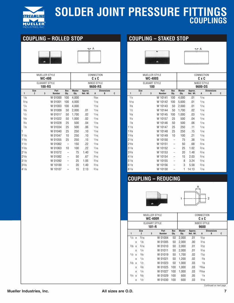
MUELLER STYLEWC-400NS
CONNECTIONC x C
ELKHART STYLE101
NIBCO STYLE9601
COUPLING – NO STOP
1/4 W 01900 100 4,000 .013/8 W 01901 50 2,000 .011/2 W 01902 50 1,700 .025/8 W 01903 100 1,000 .033/4 W 01904 25 375 .047/8 W 01905 50 500 .06
11/8 W 01906 25 250 .1113/8 W 01907 25 250 .1515/8 W 01908 10 100 .2121/8 W 01909 – 75 .3825/8 W 01910 – 50 .6831/8 W 01911 – 25 1.0641/8 W 01913 – 15 2.05
SOLDER JOINT PRESSURE FITTINGSCOUPLINGS
Mueller Industries, Inc. All sizes are O.D. 7
Size Part Box Master Approx. Dimensions1 2 3 Number Qty. Qty. Net. Wt. A B C
MUELLER STYLEWC-400S
CONNECTIONC x C
ELKHART STYLE100
NIBCO STYLE9600-DS
COUPLING – STAKED STOP
1/4 W 10141 100 4,000 .01 1/16
5/16 W 10142 100 5,600 .01 1/16
3/8 W 10143 50 2,000 .01 1/16
1/2 W 10144 50 1,700 .02 1/16
5/8 W 10145 100 1,000 .03 1/16
3/4 W 10157 25 500 .04 1/16
7/8 W 10146 50 500 .06 1/16
11/8 W 10147 25 250 .11 1/16
13/8 W 10148 25 250 .15 1/16
15/8 W 10149 10 100 .21 1/16
21/8 W 10150 – 75 .38 1/16
25/8 W 10151 – 50 .68 3/16
31/8 W 10152 – 25 1.02 3/16
35/8 W 10153 – 20 1.48 3/16
41/8 W 10154 – 15 2.03 3/16
51/8 W 10155 – 8 3.24 3/16
61/8 W 10156 – 3 5.58 3/16
81/8 W 10130 – 1 14.13 7/16
Size Part Box Master Approx. Dimensions1 2 3 Number Qty. Qty. Net. Wt. A B C
MUELLER STYLEWC-400R
CONNECTIONC x C
ELKHART STYLE101-R
NIBCO STYLE9600
COUPLING – REDUCING
1/4 x 3/16 W 01004 50 2,000 .01 5/32
x 1/8 W 01005 50 2,000 .00 3/16
3/8 x 5/16 W 01010 50 2,000 .01 3/32
x 1/4 W 01011 50 2,000 .01 3/16
1/2 x 3/8 W 01019 50 1,700 .02 7/32
x 1/4 W 01021 50 1,200 .02 3/85/8 x 1/2 W 01023 50 1,000 .03 1/8
x 3/8 W 01025 100 1,000 .03 19/64
x 1/4 W 01027 100 1,000 .03 23/64
3/4 x 5/8 W 01029 100 600 .05 1/4x 1/2 W 01030 100 600 .03 3/16
Continued on next page.
Size Part Box Master Approx. Dimensions1 2 3 Number Qty. Qty. Net. Wt. A B C
MUELLER STYLEWC-400
CONNECTIONC x C
ELKHART STYLE100-RS
NIBCO STYLE9600-RS
COUPLING – ROLLED STOP
1/8 W 01000 100 4,000 3/64
3/16 W 01001 100 4,000 1/16
1/4 W 01003 100 4,000 1/16
3/8 W 01009 50 2,000 .01 1/16
1/2 W 01017 50 1,700 .02 1/16
5/8 W 01022 50 1,000 .02 1/16
3/4 W 01028 25 500 .04 1/16
7/8 W 01034 25 500 .06 1/16
1 W 01040 25 250 .10 1/16
11/8 W 01047 10 250 .10 1/16
13/8 W 01055 25 250 .15 1/16
11/2 W 01062 – 150 .22 1/16
15/8 W 01063 10 100 .22 1/16
21/8 W 01072 – 75 1.40 1/16
25/8 W 01082 – 50 .67 3/16
31/8 W 01092 – 25 1.05 3/16
35/8 W 10100 – 20 1.40 3/16
41/8 W 10107 – 15 2.13 3/16
SOLDER JOINT PRESSURE FITTINGSCOUPLINGS / CROSS / 45˚ ELBOWS
8 * Brass Mueller Industries, Inc.All sizes are O.D.
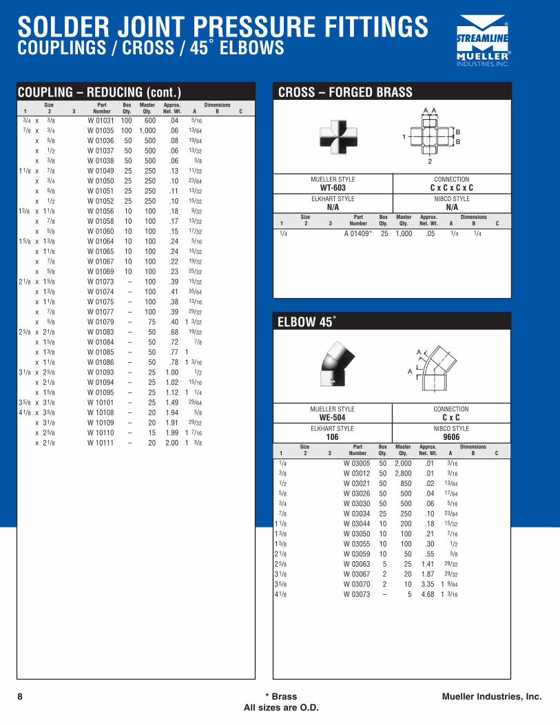
Size Part Box Master Approx. Dimensions1 2 3 Number Qty. Qty. Net. Wt. A B C
MUELLER STYLEWT-603
CONNECTIONC x C x C x C
ELKHART STYLEN/A
NIBCO STYLEN/A
CROSS – FORGED BRASS
1/4 A 01409* 25 1,000 .05 1/4 1/4
Size Part Box Master Approx. Dimensions1 2 3 Number Qty. Qty. Net. Wt. A B C
MUELLER STYLEWE-504
CONNECTIONC x C
ELKHART STYLE106
NIBCO STYLE9606
ELBOW 45˚
1/4 W 03005 50 2,000 .01 3/16
3/8 W 03012 50 2,800 .01 3/16
1/2 W 03021 50 850 .02 13/64
5/8 W 03026 50 500 .04 17/64
3/4 W 03030 50 500 .06 5/16
7/8 W 03034 25 250 .10 23/64
11/8 W 03044 10 200 .18 15/32
13/8 W 03050 10 100 .21 7/16
15/8 W 03055 10 100 .30 1/221/8 W 03059 10 50 .55 5/825/8 W 03063 5 25 1.41 29/32
31/8 W 03067 2 20 1.87 29/32
35/8 W 03070 2 10 3.35 1 9/64
41/8 W 03073 – 5 4.68 1 3/16
Size Part Box Master Approx. Dimensions1 2 3 Number Qty. Qty. Net. Wt. A B C
COUPLING – REDUCING (cont.)
3/4 x 3/8 W 01031 100 600 .04 5/16
7/8 x 3/4 W 01035 100 1,000 .06 13/64
x 5/8 W 01036 50 500 .08 19/64
x 1/2 W 01037 50 500 .06 13/32
x 3/8 W 01038 50 500 .06 3/811/8 x 7/8 W 01049 25 250 .13 11/32
x 3/4 W 01050 25 250 .10 23/64
x 5/8 W 01051 25 250 .11 13/32
x 1/2 W 01052 25 250 .10 15/32
13/8 x 11/8 W 01056 10 100 .18 9/32
x 7/8 W 01058 10 100 .17 13/32
x 5/8 W 01060 10 100 .15 17/32
15/8 x 13/8 W 01064 10 100 .24 5/16
x 11/8 W 01065 10 100 .24 15/32
x 7/8 W 01067 10 100 .22 19/32
x 5/8 W 01069 10 100 .23 25/32
21/8 x 15/8 W 01073 – 100 .39 15/32
x 13/8 W 01074 – 100 .41 35/64
x 11/8 W 01075 – 100 .38 13/16
x 7/8 W 01077 – 100 .39 29/32
x 5/8 W 01079 – 75 .40 1 3/32
25/8 x 21/8 W 01083 – 50 .68 19/32
x 15/8 W 01084 – 50 .72 7/8x 13/8 W 01085 – 50 .77 1x 11/8 W 01086 – 50 .78 1 3/16
31/8 x 25/8 W 01093 – 25 1.00 1/2x 21/8 W 01094 – 25 1.02 15/16
x 15/8 W 01095 – 25 1.12 1 1/435/8 x 31/8 W 10101 – 25 1.49 29/64
41/8 x 35/8 W 10108 – 20 1.94 5/8x 31/8 W 10109 – 20 1.91 29/32
x 25/8 W 10110 – 15 1.99 1 7/16
x 21/8 W 10111 – 20 2.00 1 5/8
SOLDER JOINT PRESSURE FITTINGS45˚ ELBOWS / 90˚ ELBOWS
Mueller Industries, Inc. All sizes are OD. 9
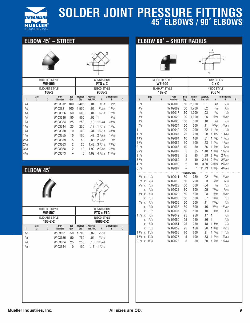
Size Part Box Master Approx. Dimensions1 2 3 Number Qty. Qty. Net. Wt. A B C
MUELLER STYLEWE-500
CONNECTIONC x C
ELKHART STYLE107-C
NIBCO STYLE9607-I
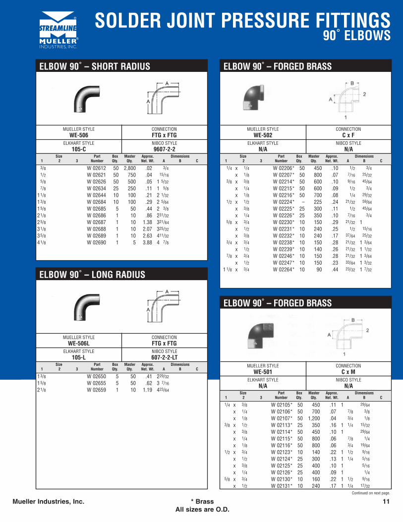
ELBOW 90˚ – SHORT RADIUS
1/4 W 02003 50 2,000 .01 3/8 3/83/8 W 02009 50 1,700 .02 3/8 3/81/2 W 02017 50 1,000 .03 1/2 1/25/8 W 02022 100 1,000 .05 19/32 19/323/4 W 02028 50 500 .10 7/8 7/87/8 W 02034 50 500 .11 53/64 53/64
1 W 02040 20 200 .22 1 1/8 1 1/811/8 W 02047 25 250 .20 1 5/64 1 5/64
13/8 W 02084 10 100 .31 1 3/32 1 3/32
15/8 W 02085 10 100 .43 1 7/32 1 7/32
21/8 W 02086 10 50 .86 1 9/16 1 9/16
25/8 W 02087 5 25 1.40 113/16 113/16
31/8 W 02088 5 25 1.99 2 1/16 2 1/16
35/8 W 02089 2 10 2.74 213/32 213/32
41/8 W 02090 2 10 3.80 223/32 223/32
61/8 W 02097 – 1 11.73 413/64 413/64 . . . . . . . . . . . . . . . . . . . . . . . . . . . . . . . . . . . . .REDUCING . . . . . . . . . . . . . . . . . . . . . . . . . . . . . . . . . . .
3/8 x 1/4 W 02011 50 750 .02 7/16 11/321/2 x 3/8 W 02019 50 750 .03 9/16 7/165/8 x 1/2 W 02023 50 500 .04 5/8 1/2
x 3/8 W 02025 50 500 .05 21/32 7/163/4 x 5/8 W 02029 50 500 .08 11/16 19/32
x 1/2 W 02030 50 500 .07 13/16 1/27/8 x 3/4 W 02035 50 500 .11 29/32 7/8
x 5/8 W 02036 50 500 .10 59/64 21/32
x 1/2 W 02037 50 500 .10 15/16 5/811/8 x 7/8 W 02049 25 250 .17 1 7/8
x 3/4 W 02050 25 250 .16 1 7/8x 5/8 W 02051 25 250 .18 1 3/16 3/4x 1/2 W 02052 25 150 .20 111/32 21/32
13/8 x 11/8 W 02056 20 200 .31 1 7/16 1 1/815/8 x 13/8 W 02077 5 100 .33 1 9/64 55/64
21/8 x 15/8 W 02078 5 50 .60 1 9/16 113/64
Size Part Box Master Approx. Dimensions1 2 3 Number Qty. Qty. Net. Wt. A B C
MUELLER STYLEWE-505
CONNECTIONFTG x C
ELKHART STYLE106-2
NIBCO STYLE9606-2
ELBOW 45˚ – STREET
3/8 W 03312 100 3,400 .01 9/16 3/16
1/2 W 03321 100 1,500 .02 21/32 13/64
5/8 W 03326 50 500 .04 13/16 17/64
3/4 W 03330 50 500 .06 1 5/16
7/8 W 03334 25 250 .10 111/64 23/64
11/8 W 03344 25 250 .17 1 7/16 15/32
13/8 W 03350 10 100 .31 113/16 25/32
15/8 W 03355 10 100 .43 2 5/64 15/16
21/8 W 03359 5 50 .86 2 3/32 5/825/8 W 03363 2 20 1.43 3 2/16 29/32
31/8 W 03368 2 10 1.92 217/32 29/32
41/8 W 03373 – 5 4.62 4 5/32 115/16
Size Part Box Master Approx. Dimensions1 2 3 Number Qty. Qty. Net. Wt. A B C
MUELLER STYLEWE-507
CONNECTIONFTG x FTG
ELKHART STYLE106-2-2
NIBCO STYLE9606-2-2
ELBOW 45˚
1/2 W 03621 50 1,700 .02 21/32
5/8 W 03626 50 750 .04 13/16
7/8 W 03634 25 250 .10 111/64
11/8 W 03644 10 100 .17 1 7/16
SOLDER JOINT PRESSURE FITTINGS90˚ ELBOWS
10 All sizes are O.D. Mueller Industries, Inc.
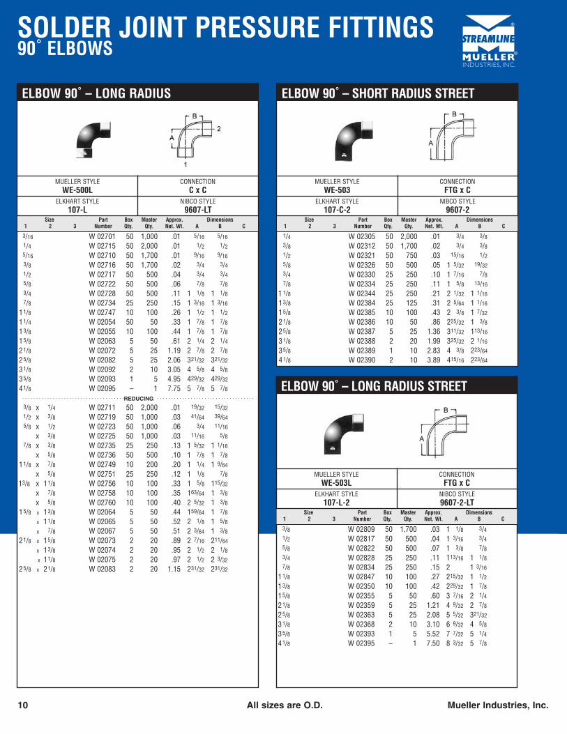
Size Part Box Master Approx. Dimensions1 2 3 Number Qty. Qty. Net. Wt. A B C
MUELLER STYLEWE-500L
CONNECTIONC x C
ELKHART STYLE107-L
NIBCO STYLE9607-LT
ELBOW 90˚ – LONG RADIUS
3/16 W 02701 50 1,000 .01 5/16 5/161/4 W 02715 50 2,000 .01 1/2 1/25/16 W 02710 50 1,700 .01 9/16 9/163/8 W 02716 50 1,700 .02 3/4 3/41/2 W 02717 50 500 .04 3/4 3/45/8 W 02722 50 500 .06 7/8 7/83/4 W 02728 50 500 .11 1 1/8 1 1/87/8 W 02734 25 250 .15 1 3/16 1 3/16
11/8 W 02747 10 100 .26 1 1/2 1 1/211/4 W 02054 50 50 .33 1 7/8 1 7/813/8 W 02055 10 100 .44 1 7/8 1 7/815/8 W 02063 5 50 .61 2 1/4 2 1/421/8 W 02072 5 25 1.19 2 7/8 2 7/825/8 W 02082 5 25 2.06 321/32 321/32
31/8 W 02092 2 10 3.05 4 5/8 4 5/835/8 W 02093 1 5 4.95 429/32 429/32
41/8 W 02095 – 1 7.75 5 7/8 5 7/8 . . . . . . . . . . . . . . . . . . . . . . . . . . . . . . . . . . . . .REDUCING . . . . . . . . . . . . . . . . . . . . . . . . . . . . . . . . . . .
3/8 x 1/4 W 02711 50 2,000 .01 19/32 15/321/2 x 3/8 W 02719 50 1,000 .03 41/64 39/645/8 x 1/2 W 02723 50 1,000 .06 3/4 11/16
x 3/8 W 02725 50 1,000 .03 11/16 5/87/8 x 3/8 W 02735 25 250 .13 1 5/32 1 1/16
x 5/8 W 02736 50 500 .10 1 7/8 1 7/811/8 x 7/8 W 02749 10 200 .20 1 1/4 1 9/64
x 5/8 W 02751 25 250 .12 1 1/8 7/813/8 x 11/8 W 02756 10 100 .33 1 5/8 115/32
x 7/8 W 02758 10 100 .35 163/64 1 3/8x 5/8 W 02760 10 100 .40 2 5/32 1 3/8
15/8 x 13/8 W 02064 5 50 .44 159/64 1 7/8x 11/8 W 02065 5 50 .52 2 1/8 1 5/8x 7/8 W 02067 5 50 .51 2 3/64 1 3/8
21/8 x 15/8 W 02073 2 20 .89 2 7/16 211/64
x 13/8 W 02074 2 20 .95 2 1/2 2 1/8x 11/8 W 02075 2 20 .97 2 1/2 2 3/32
25/8 x 21/8 W 02083 2 20 1.15 231/32 231/32
Size Part Box Master Approx. Dimensions1 2 3 Number Qty. Qty. Net. Wt. A B C
MUELLER STYLEWE-503L
CONNECTIONFTG x C
ELKHART STYLE107-L-2
NIBCO STYLE9607-2-LT
ELBOW 90˚ – LONG RADIUS STREET
3/8 W 02809 50 1,700 .03 1 1/8 3/41/2 W 02817 50 500 .04 1 3/16 3/45/8 W 02822 50 500 .07 1 3/8 7/83/4 W 02828 25 250 .11 113/16 1 1/87/8 W 02834 25 250 .15 2 1 3/16
11/8 W 02847 10 100 .27 215/32 1 1/213/8 W 02350 10 100 .42 229/32 1 7/815/8 W 02355 5 50 .60 3 7/16 2 1/421/8 W 02359 5 25 1.21 4 9/32 2 7/825/8 W 02363 5 25 2.08 5 5/32 321/32
31/8 W 02368 2 10 3.10 6 9/32 4 5/835/8 W 02393 1 5 5.52 7 7/32 5 1/441/8 W 02395 – 1 7.50 8 3/32 5 7/8
Size Part Box Master Approx. Dimensions1 2 3 Number Qty. Qty. Net. Wt. A B C
MUELLER STYLEWE-503
CONNECTIONFTG x C
ELKHART STYLE107-C-2
NIBCO STYLE9607-2
ELBOW 90˚ – SHORT RADIUS STREET
1/4 W 02305 50 2,000 .01 3/4 3/83/8 W 02312 50 1,700 .02 3/4 3/81/2 W 02321 50 750 .03 15/16 1/25/8 W 02326 50 500 .05 1 5/32 19/323/4 W 02330 25 250 .10 1 7/16 7/87/8 W 02334 25 250 .11 1 5/8 13/16
1 1/8 W 02344 25 250 .21 2 1/32 1 1/16
13/8 W 02384 25 125 .31 2 5/64 1 1/16
15/8 W 02385 10 100 .43 2 3/8 1 7/32
21/8 W 02386 10 50 .86 225/32 1 3/825/8 W 02387 5 25 1.36 311/32 113/16
31/8 W 02388 2 20 1.99 325/32 2 1/16
35/8 W 02389 1 10 2.83 4 3/8 223/64
41/8 W 02390 2 10 3.89 415/16 223/64
SOLDER JOINT PRESSURE FITTINGS90˚ ELBOWS
Mueller Industries, Inc. * Brass 11All sizes are O.D.
Size Part Box Master Approx. Dimensions1 2 3 Number Qty. Qty. Net. Wt. A B C
MUELLER STYLEWE-502
CONNECTIONC x F
ELKHART STYLEN/A
NIBCO STYLEN/A
ELBOW 90˚ – FORGED BRASS
1/4 x 1/4 W 02206* 50 450 .10 1/2 3/4x 1/8 W 02207* 50 800 .07 7/16 25/32
3/8 x 3/8 W 02214* 50 600 .10 9/16 45/64
x 1/4 W 02215* 50 600 .09 1/2 3/4x 1/8 W 02216* 50 700 .08 1/4 29/32
1/2 x 1/2 W 02224* – 225 .24 21/32 59/64
x 3/8 W 02225* 25 300 .11 1/2 45/64
x 1/4 W 02226* 25 350 .10 7/16 3/45/8 x 3/4 W 02230* 10 150 .29 21/32 1
x 1/2 W 02231* 10 240 .25 1/2 15/16
x 3/8 W 02232* 10 240 .17 37/64 25/323/4 x 3/4 W 02238* 10 150 .28 21/32 1 3/64
x 1/2 W 02239* 10 140 .26 21/32 1 1/327/8 x 3/4 W 02246* 10 150 .28 21/32 1 3/64
x 1/2 W 02247* 10 150 .23 33/64 1 3/32
1 1/8 x 3/4 W 02264* 10 90 .44 23/32 1 7/32
Size Part Box Master Approx. Dimensions1 2 3 Number Qty. Qty. Net. Wt. A B C
MUELLER STYLEWE-501
CONNECTIONC x M
ELKHART STYLEN/A
NIBCO STYLEN/A
ELBOW 90˚ – FORGED BRASS
1/4 x 3/8 W 02105* 50 450 .11 1 29/64
x 1/4 W 02106* 50 700 .07 7/8 3/8x 1/8 W 02107* 50 1,200 .04 3/4 1/8
3/8 x 1/2 W 02113* 25 350 .16 1 1/4 15/32
x 3/8 W 02114* 50 450 .10 1 29/64
x 1/4 W 02115* 50 800 .06 7/8 1/4x 1/8 W 02116* 50 800 .06 3/4 19/64
1/2 x 3/4 W 02123* 10 140 .22 1 1/2 9/16
x 1/2 W 02124* 25 300 .13 1 1/4 5/16
x 3/8 W 02125* 25 400 .10 1 5/16
x 1/4 W 02126* 25 400 .09 1 1/45/8 x 3/4 W 02130* 10 160 .22 1 1/2 9/16
x 1/2 W 02131* 10 240 .17 1 1/4 17/32
Continued on next page.
Size Part Box Master Approx. Dimensions1 2 3 Number Qty. Qty. Net. Wt. A B C
MUELLER STYLEWE-506
CONNECTIONFTG x FTG
ELKHART STYLE105-C
NIBCO STYLE9607-2-2
ELBOW 90˚ – SHORT RADIUS
3/8 W 02612 50 2,800 .02 3/41/2 W 02621 50 750 .04 15/165/8 W 02626 50 500 .05 1 5/327/8 W 02634 25 250 .11 1 5/8
11/8 W 02644 10 100 .21 2 1/32
13/8 W 02684 10 100 .29 2 5/64
15/8 W 02685 5 50 .44 2 3/821/8 W 02686 1 10 .86 231/32
25/8 W 02687 1 10 1.38 321/64
31/8 W 02688 1 10 2.07 325/32
35/8 W 02689 1 10 2.63 411/32
41/8 W 02690 1 5 3.88 4 7/8
Size Part Box Master Approx. Dimensions1 2 3 Number Qty. Qty. Net. Wt. A B C
MUELLER STYLEWE-506L
CONNECTIONFTG x FTG
ELKHART STYLE105-L
NIBCO STYLE607-2-2-LT
ELBOW 90˚ – LONG RADIUS
13/8 W 02650 5 50 .41 229/32
15/8 W 02655 5 50 .62 3 7/16
21/8 W 02659 1 10 1.19 423/64
SOLDER JOINT PRESSURE FITTINGS90˚ ELBOWS / FITTING REDUCERS / HANGERS / P-TRAPS
12 * Brass Mueller Industries, Inc.All sizes are O.D.
Size Part Box Master Approx. Dimensions1 2 3 Number Qty. Qty. Net. Wt. A B C
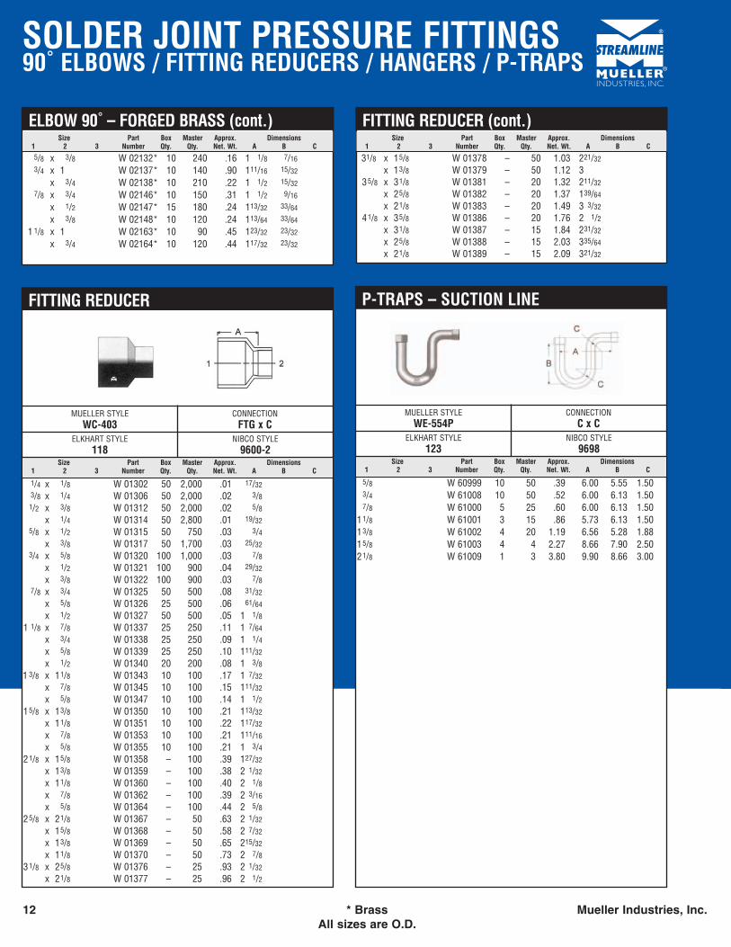
MUELLER STYLEWC-403
CONNECTIONFTG x C
ELKHART STYLE118
NIBCO STYLE9600-2
FITTING REDUCER
1/4 x 1/8 W 01302 50 2,000 .01 17/323/8 x 1/4 W 01306 50 2,000 .02 3/81/2 x 3/8 W 01312 50 2,000 .02 5/8
x 1/4 W 01314 50 2,800 .01 19/325/8 x 1/2 W 01315 50 750 .03 3/4
x 3/8 W 01317 50 1,700 .03 25/323/4 x 5/8 W 01320 100 1,000 .03 7/8
x 1/2 W 01321 100 900 .04 29/32
x 3/8 W 01322 100 900 .03 7/87/8 x 3/4 W 01325 50 500 .08 31/32
x 5/8 W 01326 25 500 .06 61/64
x 1/2 W 01327 50 500 .05 1 1/81 1/8 x 7/8 W 01337 25 250 .11 1 7/64
x 3/4 W 01338 25 250 .09 1 1/4x 5/8 W 01339 25 250 .10 111/32
x 1/2 W 01340 20 200 .08 1 3/81 3/8 x 11/8 W 01343 10 100 .17 1 7/32
x 7/8 W 01345 10 100 .15 111/32
x 5/8 W 01347 10 100 .14 1 1/215/8 x 13/8 W 01350 10 100 .21 113/32
x 11/8 W 01351 10 100 .22 117/32
x 7/8 W 01353 10 100 .21 111/16
x 5/8 W 01355 10 100 .21 1 3/421/8 x 15/8 W 01358 – 100 .39 127/32
x 13/8 W 01359 – 100 .38 2 1/32
x 11/8 W 01360 – 100 .40 2 1/8x 7/8 W 01362 – 100 .39 2 3/16
x 5/8 W 01364 – 100 .44 2 5/825/8 x 21/8 W 01367 – 50 .63 2 1/32
x 15/8 W 01368 – 50 .58 2 7/32
x 13/8 W 01369 – 50 .65 215/32
x 11/8 W 01370 – 50 .73 2 7/831/8 x 25/8 W 01376 – 25 .93 2 1/32
x 21/8 W 01377 – 25 .96 2 1/2
Size Part Box Master Approx. Dimensions1 2 3 Number Qty. Qty. Net. Wt. A B C
ELBOW 90˚ – FORGED BRASS (cont.)
5/8 x 3/8 W 02132* 10 240 .16 1 1/8 7/163/4 x 1 W 02137* 10 140 .90 111/16 15/32
x 3/4 W 02138* 10 210 .22 1 1/2 15/327/8 x 3/4 W 02146* 10 150 .31 1 1/2 9/16
x 1/2 W 02147* 15 180 .24 113/32 33/64
x 3/8 W 02148* 10 120 .24 113/64 33/64
1 1/8 x 1 W 02163* 10 90 .45 123/32 23/32
x 3/4 W 02164* 10 120 .44 117/32 23/32
Size Part Box Master Approx. Dimensions1 2 3 Number Qty. Qty. Net. Wt. A B C
FITTING REDUCER (cont.)
31/8 x 15/8 W 01378 – 50 1.03 221/32
x 13/8 W 01379 – 50 1.12 335/8 x 31/8 W 01381 – 20 1.32 211/32
x 25/8 W 01382 – 20 1.37 139/64
x 21/8 W 01383 – 20 1.49 3 3/32
41/8 x 35/8 W 01386 – 20 1.76 2 1/2x 31/8 W 01387 – 15 1.84 231/32
x 25/8 W 01388 – 15 2.03 335/64
x 21/8 W 01389 – 15 2.09 321/32
Size Part Box Master Approx. Dimensions1 2 3 Number Qty. Qty. Net. Wt. A B C
MUELLER STYLEWE-554P
CONNECTIONC x C
ELKHART STYLE123
NIBCO STYLE9698
P-TRAPS – SUCTION LINE
5/8 W 60999 10 50 .39 6.00 5.55 1.503/4 W 61008 10 50 .52 6.00 6.13 1.507/8 W 61000 5 25 .60 6.00 6.13 1.50
11/8 W 61001 3 15 .86 5.73 6.13 1.5013/8 W 61002 4 20 1.19 6.56 5.28 1.8815/8 W 61003 4 4 2.27 8.66 7.90 2.5021/8 W 61009 1 3 3.80 9.90 8.66 3.00
SOLDER JOINT PRESSURE FITTINGSPLUGS / RETURN BENDS
Mueller Industries, Inc. * Brass 13All sizes are O.D.
Size Part Box Master Approx. Dimensions1 2 3 Number Qty. Qty. Net. Wt. A B C
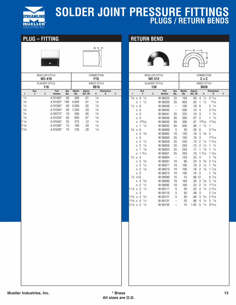
MUELLER STYLEWE-512
CONNECTIONC x C
ELKHART STYLE138
NIBCO STYLE9638
RETURN BEND
3/8 x 4 1/2 W 06025 25 150 .09 4 1/2 2 7/16
x 1 1/2 W 06020 25 850 .03 1 1/2 15/161/2 x 6 W 06048 – 100 .19 6 3 1/4
x 4 W 06045 – 200 .13 4 2 5/16
x 3 W 06041 25 225 .10 3 1 3/4x 2 W 06036 50 300 .07 2 1 1/4x 129/32 W 06035 50 300 .07 129/32 113/64
x 1 1/2 W 06032 50 500 .06 1 1/2 15/8 x 6 W 06069 5 30 .30 6 3 5/16
x 3 3/8 W 06062 10 120 .18 3 3/8 2x 3 W 06060 25 150 .16 3 113/16
x 2 1/2 W 06058 25 250 .13 2 1/2 1 9/16
x 2 1/4 W 06056 25 250 .13 2 1/4 1 1/2x 1 7/8 W 06053 25 250 .11 1 7/8 1 1/4x 1 9/16 W 06051 25 250 .10 1 9/16 1 3/32
3/4 x 4 W 06084 – 120 .23 4 1 7/8x 3 3/8 W 06081 10 90 .23 3 3/8 2 1/16
x 2 1/2 W 06077 10 100 .18 2 1/2 1 5/8x 2 1/8 W 06074 10 100 .16 2 1/8 1 7/16
x 2 W 06073 10 100 .16 2 1 3/87/8 x12 W 06099 15 15 .88 12 6 7/16
x 3 3/8 W 06095 10 100 .30 3 3/8 2 1/8x 2 1/2 W 06092 10 100 .23 2 1/2 111/16
1 1/8 x 3 1/4 W 60111 5 50 .52 3 1/4 2 3/16
x 3 W 60110 5 50 .48 3 2 1/16
13/8 x 3 3/4 W 60121 5 50 .68 3 3/4 2 9/16
15/8 x 4 1/2 W 60131 – 25 .96 4 1/2 3 1/621/8 x 5 1/2 W 60140 – 15 1.92 5 1/2 313/16
Size Part Box Master Approx. Dimensions1 2 3 Number Qty. Qty. Net. Wt. A B C
MUELLER STYLEWC-416
CONNECTIONFTG
ELKHART STYLE116
NIBCO STYLE9616
PLUG – FITTING
1/4 A 01402* 50 500 .01 1/83/8 A 01422* 100 4,000 .01 1/81/2 A 01392* 50 2,000 .02 1/85/8 A 01504* 50 1,200 .03 1/83/4 A 02273* 10 560 .05 1/87/8 A 01529* 50 600 .07 1/8
11/8 A 01556* 25 375 .12 1/813/8 A 01590* 15 180 .20 1/815/8 A 01628* 10 120 .28 1/8
SOLDER JOINT PRESSURE FITTINGSTEES
14 All sizes are OD. Mueller Industries, Inc.
Size Part Box Master Approx. Dimensions1 2 3 Number Qty. Qty. Net. Wt. A B C
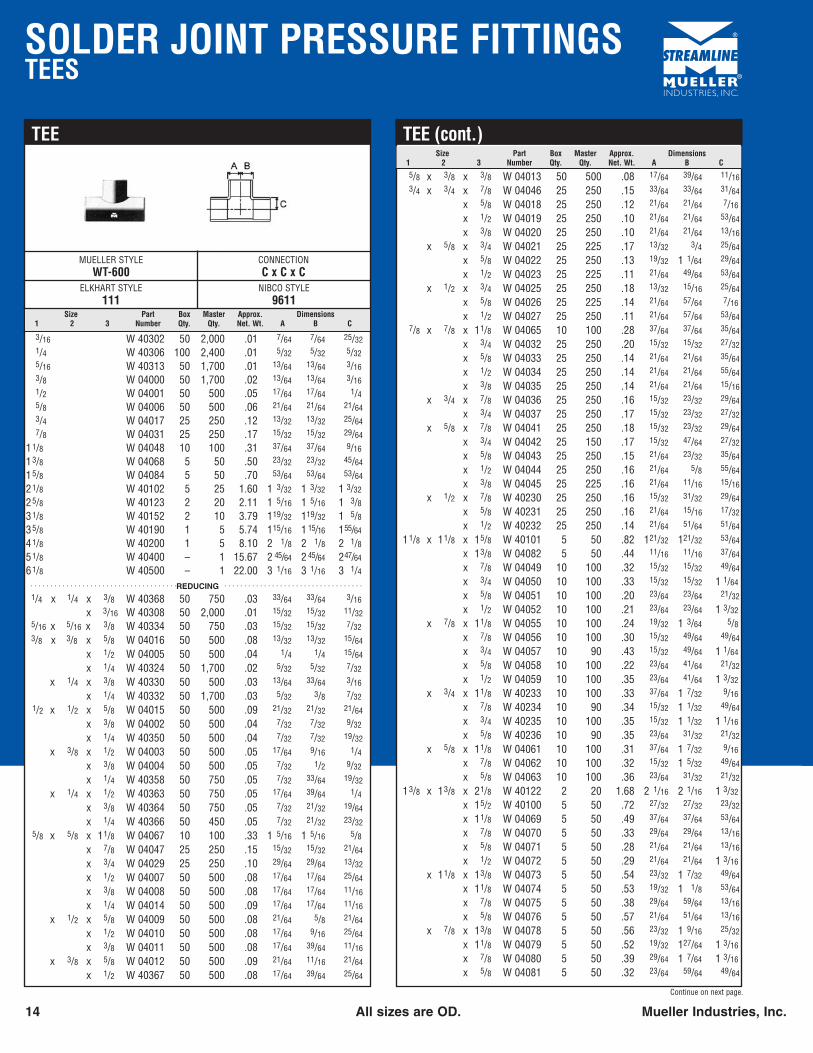
MUELLER STYLEWT-600
CONNECTIONC x C x C
ELKHART STYLE111
NIBCO STYLE9611
TEE
3/16 W 40302 50 2,000 .01 7/64 7/64 25/321/4 W 40306 100 2,400 .01 5/32 5/32 5/325/16 W 40313 50 1,700 .01 13/64 13/64 3/163/8 W 04000 50 1,700 .02 13/64 13/64 3/161/2 W 04001 50 500 .05 17/64 17/64 1/45/8 W 04006 50 500 .06 21/64 21/64 21/643/4 W 04017 25 250 .12 13/32 13/32 25/647/8 W 04031 25 250 .17 15/32 15/32 29/64
11/8 W 04048 10 100 .31 37/64 37/64 9/16
13/8 W 04068 5 50 .50 23/32 23/32 45/64
15/8 W 04084 5 50 .70 53/64 53/64 53/64
21/8 W 40102 5 25 1.60 1 3/32 1 3/32 1 3/32
25/8 W 40123 2 20 2.11 1 5/16 1 5/16 1 3/831/8 W 40152 2 10 3.79 119/32 119/32 1 5/835/8 W 40190 1 5 5.74 115/16 1 15/16 155/64
41/8 W 40200 1 5 8.10 2 1/8 2 1/8 2 1/851/8 W 40400 – 1 15.67 2 45/64 2 45/64 247/64
61/8 W 40500 – 1 22.00 3 1/16 3 1/16 3 1/4 . . . . . . . . . . . . . . . . . . . . . . . . . . . . . . . . . . . . .REDUCING . . . . . . . . . . . . . . . . . . . . . . . . . . . . . . . . . . .
1/4 x 1/4 x 3/8 W 40368 50 750 .03 33/64 33/64 3/16
x 3/16 W 40308 50 2,000 .01 15/32 15/32 11/325/16 x 5/16 x 3/8 W 40334 50 750 .03 15/32 15/32 7/323/8 x 3/8 x 5/8 W 04016 50 500 .08 13/32 13/32 15/64
x 1/2 W 04005 50 500 .04 1/4 1/4 15/64
x 1/4 W 40324 50 1,700 .02 5/32 5/32 7/32
x 1/4 x 3/8 W 40330 50 500 .03 13/64 33/64 3/16
x 1/4 W 40332 50 1,700 .03 5/32 3/8 7/321/2 x 1/2 x 5/8 W 04015 50 500 .09 21/32 21/32 21/64
x 3/8 W 04002 50 500 .04 7/32 7/32 9/32
x 1/4 W 40350 50 500 .04 7/32 7/32 19/32
x 3/8 x 1/2 W 04003 50 500 .05 17/64 9/16 1/4x 3/8 W 04004 50 500 .05 7/32 1/2 9/32
x 1/4 W 40358 50 750 .05 7/32 33/64 19/32
x 1/4 x 1/2 W 40363 50 750 .05 17/64 39/64 1/4x 3/8 W 40364 50 750 .05 7/32 21/32 19/64
x 1/4 W 40366 50 450 .05 7/32 21/32 23/325/8 x 5/8 x 11/8 W 04067 10 100 .33 1 5/16 1 5/16 5/8
x 7/8 W 04047 25 250 .15 15/32 15/32 21/64
x 3/4 W 04029 25 250 .10 29/64 29/64 13/32
x 1/2 W 04007 50 500 .08 17/64 17/64 25/64
x 3/8 W 04008 50 500 .08 17/64 17/64 11/16
x 1/4 W 04014 50 500 .09 17/64 17/64 11/16
x 1/2 x 5/8 W 04009 50 500 .08 21/64 5/8 21/64
x 1/2 W 04010 50 500 .08 17/64 9/16 25/64
x 3/8 W 04011 50 500 .08 17/64 39/64 11/16
x 3/8 x 5/8 W 04012 50 500 .09 21/64 11/16 21/64
x 1/2 W 40367 50 500 .08 17/64 39/64 25/64
Size Part Box Master Approx. Dimensions1 2 3 Number Qty. Qty. Net. Wt. A B C
TEE (cont.)
5/8 x 3/8 x 3/8 W 04013 50 500 .08 17/64 39/64 11/163/4 x 3/4 x 7/8 W 04046 25 250 .15 33/64 33/64 31/64
x 5/8 W 04018 25 250 .12 21/64 21/64 7/16
x 1/2 W 04019 25 250 .10 21/64 21/64 53/64
x 3/8 W 04020 25 250 .10 21/64 21/64 13/16
x 5/8 x 3/4 W 04021 25 225 .17 13/32 3/4 25/64
x 5/8 W 04022 25 250 .13 19/32 1 1/64 29/64
x 1/2 W 04023 25 225 .11 21/64 49/64 53/64
x 1/2 x 3/4 W 04025 25 250 .18 13/32 15/16 25/64
x 5/8 W 04026 25 225 .14 21/64 57/64 7/16
x 1/2 W 04027 25 250 .11 21/64 57/64 53/647/8 x 7/8 x 11/8 W 04065 10 100 .28 37/64 37/64 35/64
x 3/4 W 04032 25 250 .20 15/32 15/32 27/32
x 5/8 W 04033 25 250 .14 21/64 21/64 35/64
x 1/2 W 04034 25 250 .14 21/64 21/64 55/64
x 3/8 W 04035 25 250 .14 21/64 21/64 15/16
x 3/4 x 7/8 W 04036 25 250 .16 15/32 23/32 29/64
x 3/4 W 04037 25 250 .17 15/32 23/32 27/32
x 5/8 x 7/8 W 04041 25 250 .18 15/32 23/32 29/64
x 3/4 W 04042 25 150 .17 15/32 47/64 27/32
x 5/8 W 04043 25 250 .15 21/64 23/32 35/64
x 1/2 W 04044 25 250 .16 21/64 5/8 55/64
x 3/8 W 04045 25 225 .16 21/64 11/16 15/16
x 1/2 x 7/8 W 40230 25 250 .16 15/32 31/32 29/64
x 5/8 W 40231 25 250 .16 21/64 15/16 17/32
x 1/2 W 40232 25 250 .14 21/64 51/64 51/64
11/8 x 11/8 x 15/8 W 40101 5 50 .82 121/32 121/32 53/64
x 13/8 W 04082 5 50 .44 11/16 11/16 37/64
x 7/8 W 04049 10 100 .32 15/32 15/32 49/64
x 3/4 W 04050 10 100 .33 15/32 15/32 1 1/64
x 5/8 W 04051 10 100 .20 23/64 23/64 21/32
x 1/2 W 04052 10 100 .21 23/64 23/64 1 3/32
x 7/8 x 11/8 W 04055 10 100 .24 19/32 1 3/64 5/8x 7/8 W 04056 10 100 .30 15/32 49/64 49/64
x 3/4 W 04057 10 90 .43 15/32 49/64 1 1/64
x 5/8 W 04058 10 100 .22 23/64 41/64 21/32
x 1/2 W 04059 10 100 .35 23/64 41/64 1 3/32
x 3/4 x 11/8 W 40233 10 100 .33 37/64 1 7/32 9/16
x 7/8 W 40234 10 90 .34 15/32 1 1/32 49/64
x 3/4 W 40235 10 100 .35 15/32 1 1/32 1 1/16
x 5/8 W 40236 10 90 .35 23/64 31/32 21/32
x 5/8 x 11/8 W 04061 10 100 .31 37/64 1 7/32 9/16
x 7/8 W 04062 10 100 .32 15/32 1 5/32 49/64
x 5/8 W 04063 10 100 .36 23/64 31/32 21/32
13/8 x 13/8 x 21/8 W 40122 2 20 1.68 2 1/16 2 1/16 1 3/32
x 15/2 W 40100 5 50 .72 27/32 27/32 23/32
x 11/8 W 04069 5 50 .49 37/64 37/64 53/64
x 7/8 W 04070 5 50 .33 29/64 29/64 13/16
x 5/8 W 04071 5 50 .28 21/64 21/64 13/16
x 1/2 W 04072 5 50 .29 21/64 21/64 1 3/16
x 11/8 x 13/8 W 04073 5 50 .54 23/32 1 7/32 49/64
x 11/8 W 04074 5 50 .53 19/32 1 1/8 53/64
x 7/8 W 04075 5 50 .38 29/64 59/64 13/16
x 5/8 W 04076 5 50 .57 21/64 51/64 13/16
x 7/8 x 13/8 W 04078 5 50 .56 23/32 1 9/16 25/32
x 11/8 W 04079 5 50 .52 19/32 127/64 1 3/16
x 7/8 W 04080 5 50 .39 29/64 1 7/64 1 3/16
x 5/8 W 04081 5 50 .32 23/64 59/64 49/64
Continue on next page.
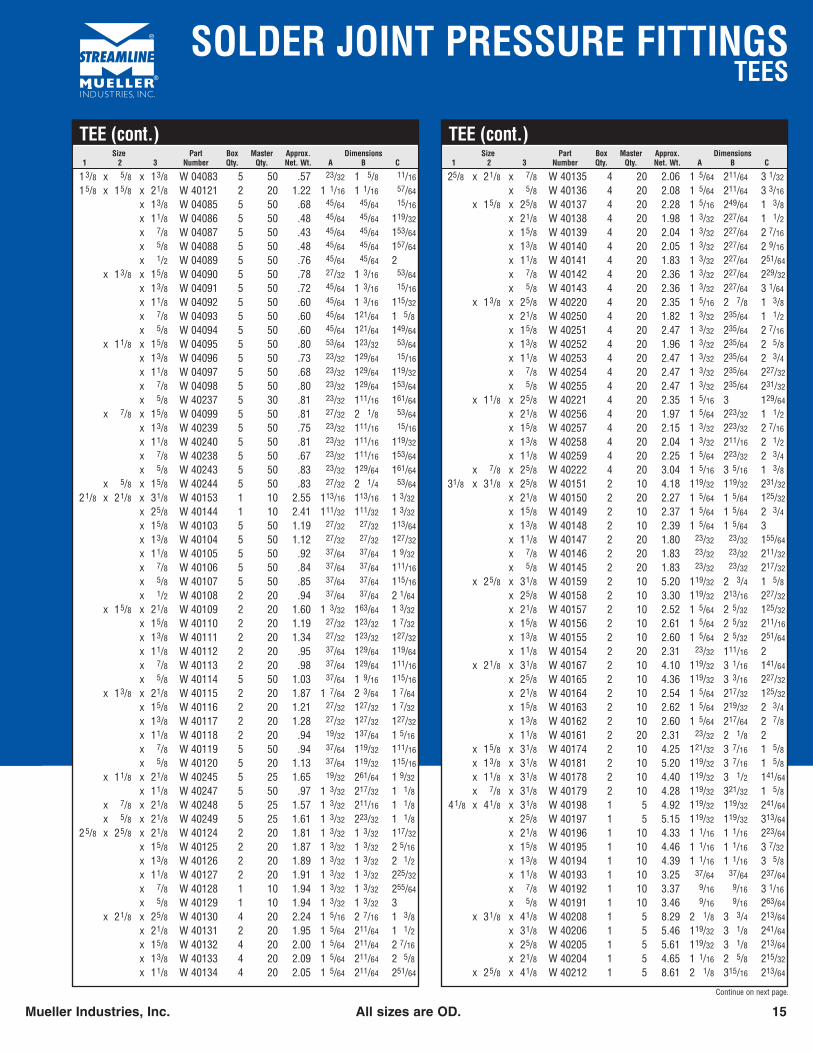
SOLDER JOINT PRESSURE FITTINGSTEES
Mueller Industries, Inc. All sizes are OD. 15
Size Part Box Master Approx. Dimensions1 2 3 Number Qty. Qty. Net. Wt. A B C
TEE (cont.)
13/8 x 5/8 x 13/8 W 04083 5 50 .57 23/32 1 5/8 11/16
15/8 x 15/8 x 21/8 W 40121 2 20 1.22 1 1/16 1 1/16 57/64
x 13/8 W 04085 5 50 .68 45/64 45/64 15/16
x 11/8 W 04086 5 50 .48 45/64 45/64 119/32
x 7/8 W 04087 5 50 .43 45/64 45/64 153/64
x 5/8 W 04088 5 50 .48 45/64 45/64 157/64
x 1/2 W 04089 5 50 .76 45/64 45/64 2x 13/8 x 15/8 W 04090 5 50 .78 27/32 1 3/16 53/64
x 13/8 W 04091 5 50 .72 45/64 1 3/16 15/16
x 11/8 W 04092 5 50 .60 45/64 1 3/16 115/32
x 7/8 W 04093 5 50 .60 45/64 121/64 1 5/8x 5/8 W 04094 5 50 .60 45/64 121/64 149/64
x 11/8 x 15/8 W 04095 5 50 .80 53/64 123/32 53/64
x 13/8 W 04096 5 50 .73 23/32 129/64 15/16
x 11/8 W 04097 5 50 .68 23/32 129/64 119/32
x 7/8 W 04098 5 50 .80 23/32 129/64 153/64
x 5/8 W 40237 5 30 .81 23/32 111/16 161/64
x 7/8 x 15/8 W 04099 5 50 .81 27/32 2 1/8 53/64
x 13/8 W 40239 5 50 .75 23/32 111/16 15/16
x 11/8 W 40240 5 50 .81 23/32 111/16 119/32
x 7/8 W 40238 5 50 .67 23/32 111/16 153/64
x 5/8 W 40243 5 50 .83 23/32 129/64 161/64
x 5/8 x 15/8 W 40244 5 50 .83 27/32 2 1/4 53/64
21/8 x 21/8 x 31/8 W 40153 1 10 2.55 113/16 113/16 1 3/32
x 25/8 W 40144 1 10 2.41 111/32 111/32 1 3/32
x 15/8 W 40103 5 50 1.19 27/32 27/32 113/64
x 13/8 W 40104 5 50 1.12 27/32 27/32 127/32
x 11/8 W 40105 5 50 .92 37/64 37/64 1 9/32
x 7/8 W 40106 5 50 .84 37/64 37/64 111/16
x 5/8 W 40107 5 50 .85 37/64 37/64 115/16
x 1/2 W 40108 2 20 .94 37/64 37/64 2 1/64
x 15/8 x 21/8 W 40109 2 20 1.60 1 3/32 163/64 1 3/32
x 15/8 W 40110 2 20 1.19 27/32 123/32 1 7/32
x 13/8 W 40111 2 20 1.34 27/32 123/32 127/32
x 11/8 W 40112 2 20 .95 37/64 129/64 119/64
x 7/8 W 40113 2 20 .98 37/64 129/64 111/16
x 5/8 W 40114 5 50 1.03 37/64 1 9/16 115/16
x 13/8 x 21/8 W 40115 2 20 1.87 1 7/64 2 3/64 1 7/64
x 15/8 W 40116 2 20 1.21 27/32 127/32 1 7/32
x 13/8 W 40117 2 20 1.28 27/32 127/32 127/32
x 11/8 W 40118 2 20 .94 19/32 137/64 1 5/16
x 7/8 W 40119 5 50 .94 37/64 119/32 111/16
x 5/8 W 40120 5 20 1.13 37/64 119/32 115/16
x 11/8 x 21/8 W 40245 5 25 1.65 19/32 261/64 1 9/32
x 11/8 W 40247 5 50 .97 1 3/32 217/32 1 1/8x 7/8 x 21/8 W 40248 5 25 1.57 1 3/32 211/16 1 1/8x 5/8 x 21/8 W 40249 5 25 1.61 1 3/32 223/32 1 1/8
25/8 x 25/8 x 21/8 W 40124 2 20 1.81 1 3/32 1 3/32 117/32
x 15/8 W 40125 2 20 1.87 1 3/32 1 3/32 2 5/16
x 13/8 W 40126 2 20 1.89 1 3/32 1 3/32 2 1/2x 11/8 W 40127 2 20 1.91 1 3/32 1 3/32 225/32
x 7/8 W 40128 1 10 1.94 1 3/32 1 3/32 255/64
x 5/8 W 40129 1 10 1.94 1 3/32 1 3/32 3x 21/8 x 25/8 W 40130 4 20 2.24 1 5/16 2 7/16 1 3/8
x 21/8 W 40131 2 20 1.95 1 5/64 211/64 1 1/2x 15/8 W 40132 4 20 2.00 1 5/64 211/64 2 7/16
x 13/8 W 40133 4 20 2.09 1 5/64 211/64 2 5/8x 11/8 W 40134 4 20 2.05 1 5/64 211/64 251/64
Size Part Box Master Approx. Dimensions1 2 3 Number Qty. Qty. Net. Wt. A B C
TEE (cont.)
25/8 x 21/8 x 7/8 W 40135 4 20 2.06 1 5/64 211/64 3 1/32
x 5/8 W 40136 4 20 2.08 1 5/64 211/64 3 3/16
x 15/8 x 25/8 W 40137 4 20 2.28 1 5/16 249/64 1 3/8x 21/8 W 40138 4 20 1.98 1 3/32 227/64 1 1/2x 15/8 W 40139 4 20 2.04 1 3/32 227/64 2 7/16
x 13/8 W 40140 4 20 2.05 1 3/32 227/64 2 9/16
x 11/8 W 40141 4 20 1.83 1 3/32 227/64 251/64
x 7/8 W 40142 4 20 2.36 1 3/32 227/64 229/32
x 5/8 W 40143 4 20 2.36 1 3/32 227/64 3 1/64
x 13/8 x 25/8 W 40220 4 20 2.35 1 5/16 2 7/8 1 3/8x 21/8 W 40250 4 20 1.82 1 3/32 235/64 1 1/2x 15/8 W 40251 4 20 2.47 1 3/32 235/64 2 7/16
x 13/8 W 40252 4 20 1.96 1 3/32 235/64 2 5/8x 11/8 W 40253 4 20 2.47 1 3/32 235/64 2 3/4x 7/8 W 40254 4 20 2.47 1 3/32 235/64 227/32
x 5/8 W 40255 4 20 2.47 1 3/32 235/64 231/32
x 11/8 x 25/8 W 40221 4 20 2.35 1 5/16 3 129/64
x 21/8 W 40256 4 20 1.97 1 5/64 223/32 1 1/2x 15/8 W 40257 4 20 2.15 1 3/32 223/32 2 7/16
x 13/8 W 40258 4 20 2.04 1 3/32 211/16 2 1/2x 11/8 W 40259 4 20 2.25 1 5/64 223/32 2 3/4
x 7/8 x 25/8 W 40222 4 20 3.04 1 5/16 3 5/16 1 3/831/8 x 31/8 x 25/8 W 40151 2 10 4.18 119/32 119/32 231/32
x 21/8 W 40150 2 20 2.27 1 5/64 1 5/64 125/32
x 15/8 W 40149 2 10 2.37 1 5/64 1 5/64 2 3/4x 13/8 W 40148 2 10 2.39 1 5/64 1 5/64 3x 11/8 W 40147 2 20 1.80 23/32 23/32 155/64
x 7/8 W 40146 2 20 1.83 23/32 23/32 211/32
x 5/8 W 40145 2 20 1.83 23/32 23/32 217/32
x 25/8 x 31/8 W 40159 2 10 5.20 119/32 2 3/4 1 5/8x 25/8 W 40158 2 10 3.30 119/32 213/16 227/32
x 21/8 W 40157 2 10 2.52 1 5/64 2 5/32 125/32
x 15/8 W 40156 2 10 2.61 1 5/64 2 5/32 211/16
x 13/8 W 40155 2 10 2.60 1 5/64 2 5/32 251/64
x 11/8 W 40154 2 20 2.31 23/32 111/16 2x 21/8 x 31/8 W 40167 2 10 4.10 119/32 3 1/16 141/64
x 25/8 W 40165 2 10 4.36 119/32 3 3/16 227/32
x 21/8 W 40164 2 10 2.54 1 5/64 217/32 125/32
x 15/8 W 40163 2 10 2.62 1 5/64 219/32 2 3/4x 13/8 W 40162 2 10 2.60 1 5/64 217/64 2 7/8x 11/8 W 40161 2 20 2.31 23/32 2 1/8 2
x 15/8 x 31/8 W 40174 2 10 4.25 121/32 3 7/16 1 5/8x 13/8 x 31/8 W 40181 2 10 5.20 119/32 3 7/16 1 5/8x 11/8 x 31/8 W 40178 2 10 4.40 119/32 3 1/2 141/64
x 7/8 x 31/8 W 40179 2 10 4.28 119/32 321/32 1 5/841/8 x 41/8 x 31/8 W 40198 1 5 4.92 119/32 119/32 241/64
x 25/8 W 40197 1 5 5.15 119/32 119/32 313/64
x 21/8 W 40196 1 10 4.33 1 1/16 1 1/16 223/64
x 15/8 W 40195 1 10 4.46 1 1/16 1 1/16 3 7/32
x 13/8 W 40194 1 10 4.39 1 1/16 1 1/16 3 5/8x 11/8 W 40193 1 10 3.25 37/64 37/64 237/64
x 7/8 W 40192 1 10 3.37 9/16 9/16 3 1/16
x 5/8 W 40191 1 10 3.46 9/16 9/16 263/64
x 31/8 x 41/8 W 40208 1 5 8.29 2 1/8 3 3/4 213/64
x 31/8 W 40206 1 5 5.46 119/32 3 1/8 241/64
x 25/8 W 40205 1 5 5.61 119/32 3 1/8 213/64
x 21/8 W 40204 1 5 4.65 1 1/16 2 5/8 215/32
x 25/8 x 41/8 W 40212 1 5 8.61 2 1/8 315/16 213/64
Continue on next page.
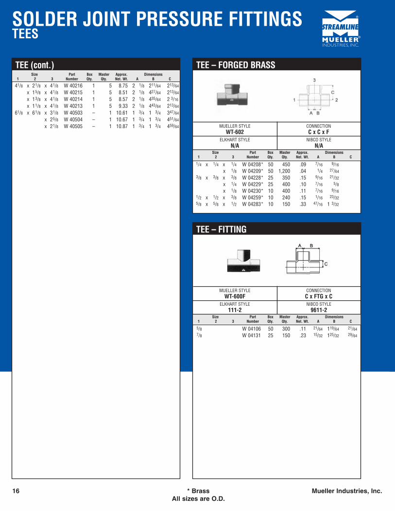
SOLDER JOINT PRESSURE FITTINGSTEES
16 * Brass Mueller Industries, Inc.All sizes are O.D.
Size Part Box Master Approx. Dimensions1 2 3 Number Qty. Qty. Net. Wt. A B C
TEE (cont.)
41/8 x 21/8 x 41/8 W 40216 1 5 8.75 2 1/8 211/64 213/64
x 15/8 x 41/8 W 40215 1 5 8.51 2 1/8 427/64 213/64
x 13/8 x 41/8 W 40214 1 5 8.57 2 1/8 435/64 2 3/16
x 11/8 x 41/8 W 40213 1 5 9.33 2 1/8 443/64 213/64
61/8 x 61/8 x 31/8 W 40503 – 1 10.61 1 3/4 1 3/4 347/64
x 25/8 W 40504 – 1 10.67 1 3/4 1 3/4 451/64
x 21/8 W 40505 – 1 10.87 1 3/4 1 3/4 459/64
Size Part Box Master Approx. Dimensions1 2 3 Number Qty. Qty. Net. Wt. A B C
MUELLER STYLEWT-602
CONNECTIONC x C x F
ELKHART STYLEN/A
NIBCO STYLEN/A
TEE – FORGED BRASS
1/4 x 1/4 x 1/4 W 04208* 50 450 .09 7/16 9/16
x 1/8 W 04209* 50 1,200 .04 1/4 27/643/8 x 3/8 x 3/8 W 04228* 25 350 .15 9/16 21/32
x 1/4 W 04229* 25 400 .10 7/16 5/8x 1/8 W 04230* 10 400 .11 7/16 9/16
1/2 x 1/2 x 3/8 W 04259* 10 240 .15 1/16 23/325/8 x 5/8 x 1/2 W 04283* 10 150 .33 47/16 1 3/32
Size Part Box Master Approx. Dimensions1 2 3 Number Qty. Qty. Net. Wt. A B C
MUELLER STYLEWT-600F
CONNECTIONC x FTG x C
ELKHART STYLE111-2
NIBCO STYLE9611-2
TEE – FITTING
5/8 W 04106 50 300 .11 21/64 119/64 21/647/8 W 04131 25 150 .23 15/32 125/32 29/64
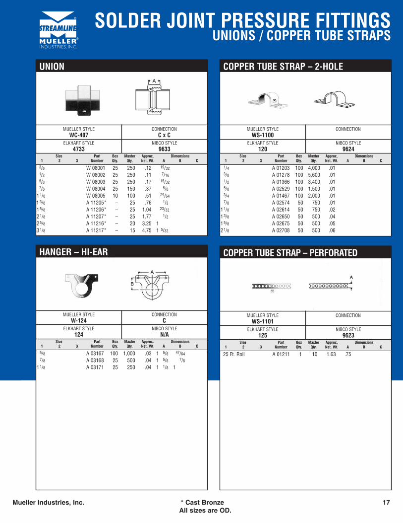
SOLDER JOINT PRESSURE FITTINGSUNIONS / COPPER TUBE STRAPS
Mueller Industries, Inc. * Cast Bronze 17All sizes are OD.
Size Part Box Master Approx. Dimensions1 2 3 Number Qty. Qty. Net. Wt. A B C
MUELLER STYLEWC-407
CONNECTIONC x C
ELKHART STYLE4733
NIBCO STYLE9633
UNION
3/8 W 08001 25 250 .12 19/321/2 W 08002 25 250 .11 7/165/8 W 08003 25 250 .17 15/327/8 W 08004 25 150 .37 5/8
11/8 W 08005 10 100 .51 29/64
1 3/8 A 11205* – 25 .76 1/215/8 A 11206* – 25 1.04 23/32
21/8 A 11207* – 25 1.77 1/225/8 A 11216* – 20 3.25 131/8 A 11217* – 15 4.75 1 5/32
Size Part Box Master Approx. Dimensions1 2 3 Number Qty. Qty. Net. Wt. A B C
MUELLER STYLEWS-1100
CONNECTION
ELKHART STYLE120
NIBCO STYLE9624
COPPER TUBE STRAP – 2-HOLE
1/4 A 01203 100 4,000 .013/8 A 01278 100 5,600 .011/2 A 01366 100 3,400 .015/8 A 02529 100 1,500 .013/4 A 01467 100 2,000 .017/8 A 02574 50 750 .01
11/8 A 02614 50 750 .0213/8 A 02650 50 500 .0415/8 A 02675 50 500 .0521/8 A 02708 50 500 .06
Size Part Box Master Approx. Dimensions1 2 3 Number Qty. Qty. Net. Wt. A B C
MUELLER STYLEWS-1101
CONNECTION
ELKHART STYLE125
NIBCO STYLE9623
COPPER TUBE STRAP – PERFORATED
25 Ft. Roll A 01211 1 10 1.63 .75
Size Part Box Master Approx. Dimensions1 2 3 Number Qty. Qty. Net. Wt. A B C
MUELLER STYLEW-124
CONNECTIONC
ELKHART STYLE124
NIBCO STYLEN/A
HANGER – HI-EAR
5/8 A 03167 100 1,000 .03 1 5/8 47/647/8 A 03168 25 500 .04 1 5/8 7/8
11/8 A 03171 25 250 .04 1 1/8 1
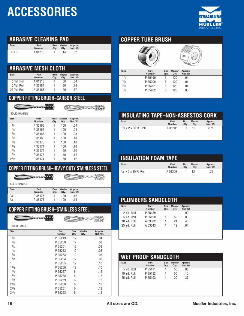
ACCESSORIES
18 All sizes are OD. Mueller Industries, Inc.
Size Part Box Master Approx.Number Qty. Qty. Net. Wt
COPPER FITTING BRUSH–CARBON STEEL
1/4 P 35166 1 100 .043/8 P 35167 1 100 .081/2 P 35168 1 100 .085/8 P 35169 1 100 .107/8 P 35170 1 100 .10
11/8 P 35171 1 100 .1013/8 P 35172 1 50 .1015/8 P 35173 1 50 .1221/8 P 35174 1 50 .12
SOLID HANDLE
Size Part Box Master Approx.Number Qty. Qty. Net. Wt
COPPER TUBE BRUSH
1/4 P 35199 6 120 .043/8 P 35200 6 120 .045/8 P 35201 6 120 .047/8 P 35202 6 120 .08
Size Part Box Master Approx.Number Qty. Qty. Net. Wt
COPPER FITTING BRUSH–HEAVY DUTY STAINLESS STEEL
5/8 P 35175 1 100 .127/8 P 35176 1 100 .14
SOLID HANDLE
Size Part Box Master Approx.Number Qty Qty. Net. Wt.
COPPER FITTING BRUSH–STAINLESS STEEL
1/4 P 35249 12 .043/8 P 35250 12 .081/2 P 35251 12 .085/8 P 35252 12 .083/4 P 35253 12 .087/8 P 35254 12 .08
1 P 35255 12 .1011/8 P 35256 12 .1013/8 P 35257 6 .1211/2 P 35258 6 .1215/8 P 35259 6 .1221/8 P 35260 6 .1223/8 P 35261 6 .1225/8 P 35262 6 .12
SOLID HANDLE
Size Part Box Master Approx.Number Qty Qty. Net. Wt.
INSULATING TAPE–NON-ASBESTOS CORK
1/8 x 2 x 30 Ft. Roll A 01208 1 12 2.75
Size Part Box Master Approx.Number Qty Qty. Net. Wt.
INSULATION FOAM TAPE
1/8 x 2 x 30 Ft. Roll A 01209 1 12 .75
Size Part Box Master Approx.Number Qty. Qty. Net. Wt
ABRASIVE MESH CLOTH
5 Yd. Roll A 01215 1 50 .0410 Yd. Roll P 35187 1 50 .1525 Yd. Roll P 35188 1 20 .37
Size Part Box Master Approx.Number Qty. Qty. Net. Wt
ABRASIVE CLEANING PAD
4 x 6 A 01210 1 14 .32
Size Part Box Master Approx.Number Qty. Qty. Net. Wt
PLUMBERS SANDCLOTH
2 Yd. Roll P 35189 .025 Yd. Roll P 35190 1 50 .06
10 Yd. Roll A 03382 1 24 .4525 Yd. Roll A 03343 1 12 .94
Size Part Box Master Approx.Number Qty. Qty. Net. Wt
WET PROOF SANDCLOTH
5 Yd. Roll P 35191 1 50 .0610 Yd. Roll P 35192 1 50 .1525 Yd. Roll P 35193 1 20 .37
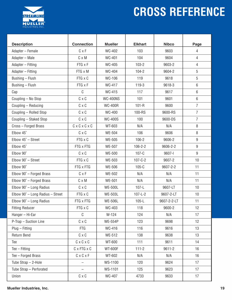
CROSS REFERENCE
Mueller Industries, Inc. 19
Description Connection Mueller Elkhart Nibco Page
Adapter – Female C x F WC-402 103 9603 4
Adapter – Male C x M WC-401 104 9604 4
Adapter – Fitting FTG x F WC-405 103-2 9603-2 4
Adapter – Fitting FTG x M WC-404 104-2 9604-2 5
Bushing – Flush FTG x C WC-106 119 9618 5
Bushing – Flush FTG x F WC-417 119-3 9618-3 6
Cap C WC-415 117 9617 6
Coupling – No Stop C x C WC-400NS 101 9601 6
Coupling – Reducing C x C WC-400R 101-R 9600 7
Coupling – Rolled Stop C x C WC-400 100-RS 9600-RS 7
Coupling – Staked Stop C x C WC-400S 100 9600-DS 7
Cross – Forged Brass C x C x C x C WT-603 N/A N/A 8
Elbow 45˚ C x C WE-504 106 9606 8
Elbow 45˚ – Street FTG x C WE-505 106-2 9606-2 9
Elbow 45˚ FTG x FTG WE-507 106-2-2 9606-2-2 9
Elbow 90˚ C x C WE-500 107-C 9607-I 9
Elbow 90˚ – Street FTG x C WE-503 107-C-2 9607-2 10
Elbow 90˚ FTG x FTG WE-506 105-C 9607-2-2 11
Elbow 90˚ – Forged Brass C x F WE-502 N/A N/A 11
Elbow 90˚ – Forged Brass C x M WE-501 N/A N/A 11
Elbow 90˚ – Long Radius C x C WE-500L 107-L 9607-LT 10
Elbow 90˚ – Long Radius – Street FTG x C WE-503L 107-L-2 9607-2-LT 10
Elbow 90˚ – Long Radius FTG x FTG WE-506L 105-L 9607-2-2-LT 11
Fitting Reducer FTG x C WC-403 118 9600-2 12
Hanger – Hi-Ear C W-124 124 N/A 17
P-Trap – Suction Line C x C WE-554P 123 9698 12
Plug – Fitting FTG WC-416 116 9616 13
Return Bend C x C WE-512 138 9638 13
Tee C x C x C WT-600 111 9611 14
Tee – Fitting C x FTG x C WT-600F 111-2 9611-2 16
Tee – Forged Brass C x C x F WT-602 N/A N/A 16
Tube Strap – 2-Hole – WS-1100 120 9624 17
Tube Strap – Perforated – WS-1101 125 9623 17
Union C x C WC-407 4733 9633 17
COPPER TUBE DATA
20 Mueller Industries, Inc.
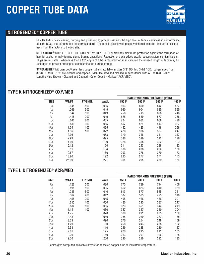
NITROGENIZED® COPPER TUBEMueller Industries’ cleaning, purging and pressurizing process assures the high level of tube cleanliness in conformanceto astm B280, the refrigeration industry standard. The tube is sealed with plugs which maintain the standard of cleanli-ness from the factory to the job site.
STREAMLINE® COPPER TUBE PRESSURIZED WITH NITROGEN provides maximum protection against the formation ofharmful oxides normally formed during brazing operations. Reduction of these oxides greatly reduces system comtamination.Plugs are reusable. When less than a 20’ length of tube is required for an installation the unused length of tube may bereplugged to prevent atmospheric contamination during storage.
STREAMLINE® Nitrogenized® seamless copper tube is available in sizes 3/8” OD thru 3-1/8” OD. Larger sizes from 3-5/8 OD thru 8-1/8” are cleaned and capped. Manufactured and cleaned in Accordance with ASTM B280. 20-ft.Lengths Hard Drawn - Cleaned and Capped - Color Coded - Marked “ACR/MED”.
TYPE K NITROGENIZED® OXY/MEDRATED WORKING PRESSURE (PSIG)
SIZE WT/FT FT/BNDL WALL 150 F 200 F 300 F 400 F3/8 .145 500 .035 913 860 842 5371/2 .269 500 .049 960 904 885 5655/8 .344 500 .049 758 713 698 4463/4 .418 200 .049 626 589 577 3687/8 .641 200 .065 724 682 668 426
11/8 .839 100 .065 557 524 513 32713/8 1.04 100 .065 452 425 416 26615/8 1.36 100 .072 420 396 387 24721/8 2.06 .083 370 348 341 21725/8 2.93 .095 338 319 312 19931/8 4.00 .109 328 308 302 19335/8 5.12 .120 311 293 286 18341/8 6.51 .134 306 288 282 18051/8 9.67 .160 293 276 270 17261/8 13.90 .192 295 277 271 17381/8 25.90 .271 314 295 289 184
Tables give computed allowable stress for annealed copper tube at indicated temperature.
TYPE L NITROGENIZED® ACR/MEDRATED WORKING PRESSURE (PSIG)
SIZE WT/FT FT/BNDL WALL 150 F 200 F 300 F 400 F3/8 .126 500 .030 775 729 714 4561/2 .198 500 .035 662 623 610 3895/8 .285 500 .040 613 577 565 3613/4 .362 200 .042 537 505 495 3167/8 .455 200 .045 495 466 456 291
11/8 .655 100 .050 420 395 387 24713/8 .884 100 .055 373 351 344 21915/8 1.14 100 .060 347 327 320 20421/8 1.75 .070 309 291 285 18225/8 2.48 .080 285 269 263 16831/8 3.33 .090 270 254 248 15935/8 4.29 .100 258 243 238 15241/8 5.38 .110 249 235 230 14751/8 7.61 .125 229 215 211 13561/8 10.20 .140 213 201 196 12581/8 19.30 .200 230 216 212 135
Mueller Industries, Inc. 21
COPPER TUBE DATA
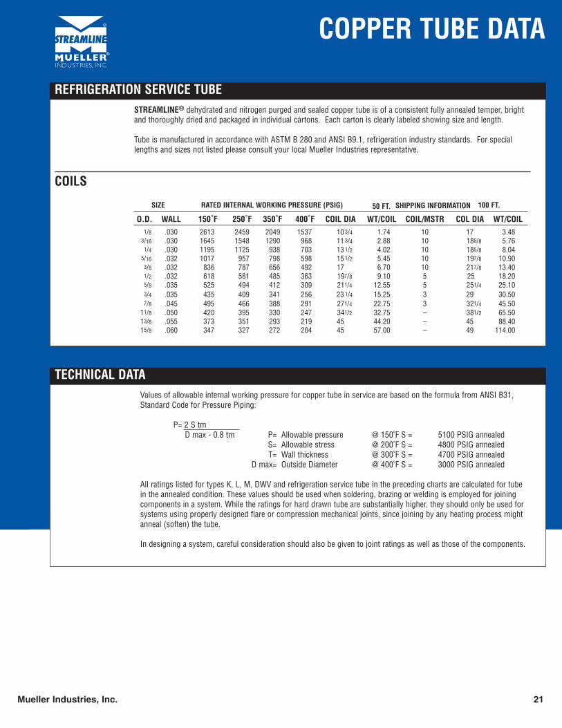
REFRIGERATION SERVICE TUBESTREAMLINE® dehydrated and nitrogen purged and sealed copper tube is of a consistent fully annealed temper, brightand thoroughly dried and packaged in individual cartons. Each carton is clearly labeled showing size and length.
Tube is manufactured in accordance with ASTM B 280 and ANSI B9.1, refrigeration industry standards. For speciallengths and sizes not listed please consult your local Mueller Industries representative.
COILS
O.D. WALL 150˚F 250˚F 350˚F 400˚F COIL DIA WT/COIL COIL/MSTR COL DIA WT/COIL1/8 .030 2613 2459 2049 1537 10 3/4 1.74 10 17 3.48
3/16 .030 1645 1548 1290 968 11 3/4 2.88 10 185/8 5.761/4 .030 1195 1125 938 703 13 1/2 4.02 10 185/8 8.04
5/16 .032 1017 957 798 598 15 1/2 5.45 10 197/8 10.903/8 .032 836 787 656 492 17 6.70 10 217/8 13.401/2 .032 618 581 485 363 197/8 9.10 5 25 18.205/8 .035 525 494 412 309 211/4 12.55 5 251/4 25.103/4 .035 435 409 341 256 23 1/4 15.25 3 29 30.507/8 .045 495 466 388 291 271/4 22.75 3 321/4 45.50
11/8 .050 420 395 330 247 341/2 32.75 – 381/2 65.5013/8 .055 373 351 293 219 45 44.20 – 45 88.4015/8 .060 347 327 272 204 45 57.00 – 49 114.00
100 FT.50 FT. SHIPPING INFORMATIONSIZE RATED INTERNAL WORKING PRESSURE (PSIG)
TECHNICAL DATAValues of allowable internal working pressure for copper tube in service are based on the formula from ANSI B31,Standard Code for Pressure Piping:
P= 2 S tmD max - 0.8 tm P= Allowable pressure @ 150˚F S = 5100 PSIG annealed
S= Allowable stress @ 200˚F S = 4800 PSIG annealedT= Wall thickness @ 300˚F S = 4700 PSIG annealed
D max= Outside Diameter @ 400˚F S = 3000 PSIG annealed
All ratings listed for types K, L, M, DWV and refrigeration service tube in the preceding charts are calculated for tubein the annealed condition. These values should be used when soldering, brazing or welding is employed for joiningcomponents in a system. While the ratings for hard drawn tube are substantially higher, they should only be used forsystems using properly designed flare or compression mechanical joints, since joining by any heating process mightanneal (soften) the tube.
In designing a system, careful consideration should also be given to joint ratings as well as those of the components.
22 Mueller Industries, Inc.
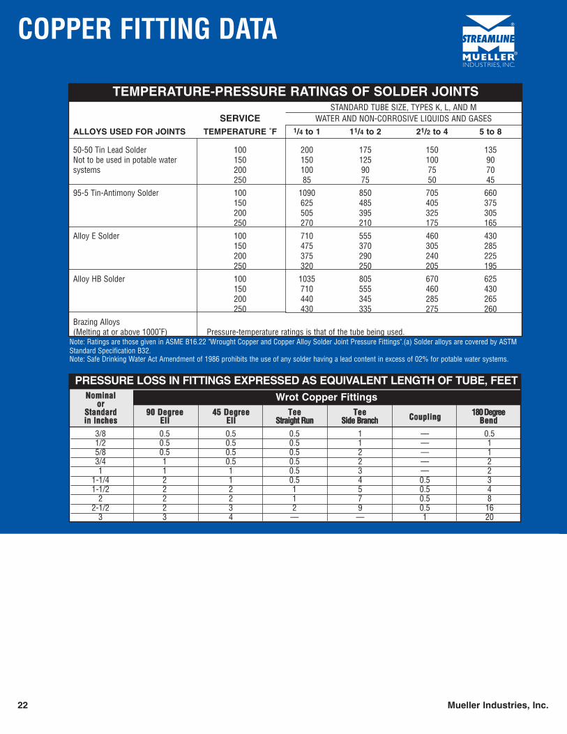
COPPER FITTING DATA
NNoommiinnaalloorr
SSttaannddaarrdd 9900 DDeeggrreeee 4455 DDeeggrreeee TTeeee TTeeee CCoouupplliinngg 118800 DDeeggrreeeeiinn IInncchheess EEllll EEllll SSttrraaiigghhtt RRuunn SSiiddee BBrraanncchh BBeenndd
Wrot Copper Fittings
3/8 0.5 0.5 0.5 1 — 0.51/2 0.5 0.5 0.5 1 — 15/8 0.5 0.5 0.5 2 — 13/4 1 0.5 0.5 2 — 21 1 1 0.5 3 — 2
1-1/4 2 1 0.5 4 0.5 31-1/2 2 2 1 5 0.5 4
2 2 2 1 7 0.5 82-1/2 2 3 2 9 0.5 16
3 3 4 — — 1 20
PRESSURE LOSS IN FITTINGS EXPRESSED AS EQUIVALENT LENGTH OF TUBE, FEET
STANDARD TUBE SIZE, TYPES K, L, AND MSERVICE WATER AND NON-CORROSIVE LIQUIDS AND GASES
ALLOYS USED FOR JOINTS TEMPERATURE ˚F 1/4 to 1 11/4 to 2 21/2 to 4 5 to 8
50-50 Tin Lead Solder 100 200 175 150 135Not to be used in potable water 150 150 125 100 90systems 200 100 90 75 70
250 85 75 50 45
95-5 Tin-Antimony Solder 100 1090 850 705 660150 625 485 405 375200 505 395 325 305250 270 210 175 165
Alloy E Solder 100 710 555 460 430150 475 370 305 285200 375 290 240 225250 320 250 205 195
Alloy HB Solder 100 1035 805 670 625150 710 555 460 430200 440 345 285 265250 430 335 275 260
Brazing Alloys(Melting at or above 1000˚F) Pressure-temperature ratings is that of the tube being used.
TEMPERATURE-PRESSURE RATINGS OF SOLDER JOINTS
Note: Ratings are those given in ASME B16.22 "Wrought Copper and Copper Alloy Solder Joint Pressure Fittings".(a) Solder alloys are covered by ASTMStandard Specification B32.Note: Safe Drinking Water Act Amendment of 1986 prohibits the use of any solder having a lead content in excess of 02% for potable water systems.
SPECIFICATIONS & STANDARDS
Mueller Industries, Inc. 23
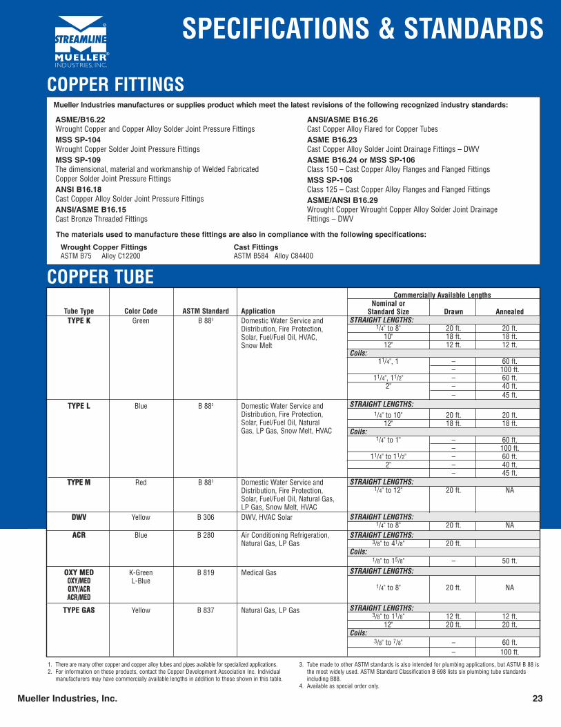
COPPER TUBE
1. There are many other copper and copper alloy tubes and pipes available for specialized applications.2. For information on these products, contact the Copper Development Association Inc. Individual
manufacturers may have commercially available lengths in addition to those shown in this table.
3. Tube made to other ASTM standards is also intended for plumbing applications, but ASTM B 88 isthe most widely used. ASTM Standard Classification B 698 lists six plumbing tube standardsincluding B88.
4. Available as special order only.
Tube Type Color Code ASTM Standard ApplicationTTYYPPEE KK Green B 883 Domestic Water Service and
Distribution, Fire Protection,Solar, Fuel/Fuel Oil, HVAC,Snow Melt
TTYYPPEE LL Blue B 883 Domestic Water Service andDistribution, Fire Protection,Solar, Fuel/Fuel Oil, Natural Gas, LP Gas, Snow Melt, HVAC
TTYYPPEE MM Red B 883 Domestic Water Service andDistribution, Fire Protection,Solar, Fuel/Fuel Oil, Natural Gas,LP Gas, Snow Melt, HVAC
DDWWVV Yellow B 306 DWV, HVAC Solar
AACCRR Blue B 280 Air Conditioning Refrigeration,Natural Gas, LP Gas
OOXXYY MMEEDD K-Green B 819 Medical GasOOXXYY//MMEEDD L-BlueOOXXYY//AACCRRAACCRR//MMEEDD
TTYYPPEE GGAASS Yellow B 837 Natural Gas, LP Gas
Commercially Available LengthsNominal or
Standard Size Drawn AnnealedSTRAIGHT LENGTHS:
1/4" to 8" 20 ft. 20 ft.10" 18 ft. 18 ft.12" 12 ft. 12 ft.
Coils:11/4", 1 – 60 ft.
– 100 ft.11/4", 11/2" – 60 ft.
2" – 40 ft.– 45 ft.
STRAIGHT LENGTHS:1/4" to 10" 20 ft. 20 ft.
12" 18 ft. 18 ft.Coils:
1/4" to 1" – 60 ft.– 100 ft.
11/4" to 11/2" – 60 ft.2" – 40 ft.
– 45 ft.STRAIGHT LENGTHS:
1/4" to 12" 20 ft. NA
STRAIGHT LENGTHS:1/4" to 8" 20 ft. NA
STRAIGHT LENGTHS:3/8" to 41/8" 20 ft.
Coils:1/8" to 15/8" – 50 ft.
STRAIGHT LENGTHS:
1/4" to 8" 20 ft. NA
STRAIGHT LENGTHS:3/8" to 11/8" 12 ft. 12 ft.
12" 20 ft. 20 ft.Coils:
3/8" to 7/8" – 60 ft.– 100 ft.
ASME/B16.22Wrought Copper and Copper Alloy Solder Joint Pressure FittingsMSS SP-104Wrought Copper Solder Joint Pressure FittingsMSS SP-109The dimensional, material and workmanship of Welded FabricatedCopper Solder Joint Pressure FittingsANSI B16.18Cast Copper Alloy Solder Joint Pressure FittingsANSI/ASME B16.15Cast Bronze Threaded Fittings
ANSI/ASME B16.26Cast Copper Alloy Flared for Copper TubesASME B16.23Cast Copper Alloy Solder Joint Drainage Fittings – DWVASME B16.24 or MSS SP-106 Class 150 – Cast Copper Alloy Flanges and Flanged FittingsMSS SP-106Class 125 – Cast Copper Alloy Flanges and Flanged FittingsASME/ANSI B16.29Wrought Copper Wrought Copper Alloy Solder Joint DrainageFittings – DWV
Wrought Copper FittingsASTM B75 Alloy C12200
Cast FittingsASTM B584 Alloy C84400
The materials used to manufacture these fittings are also in compliance with the following specifications:
Mueller Industries manufactures or supplies product which meet the latest revisions of the following recognized industry standards:
COPPER FITTINGS
INSTALLATION INFORMATION
24 Mueller Industries, Inc.
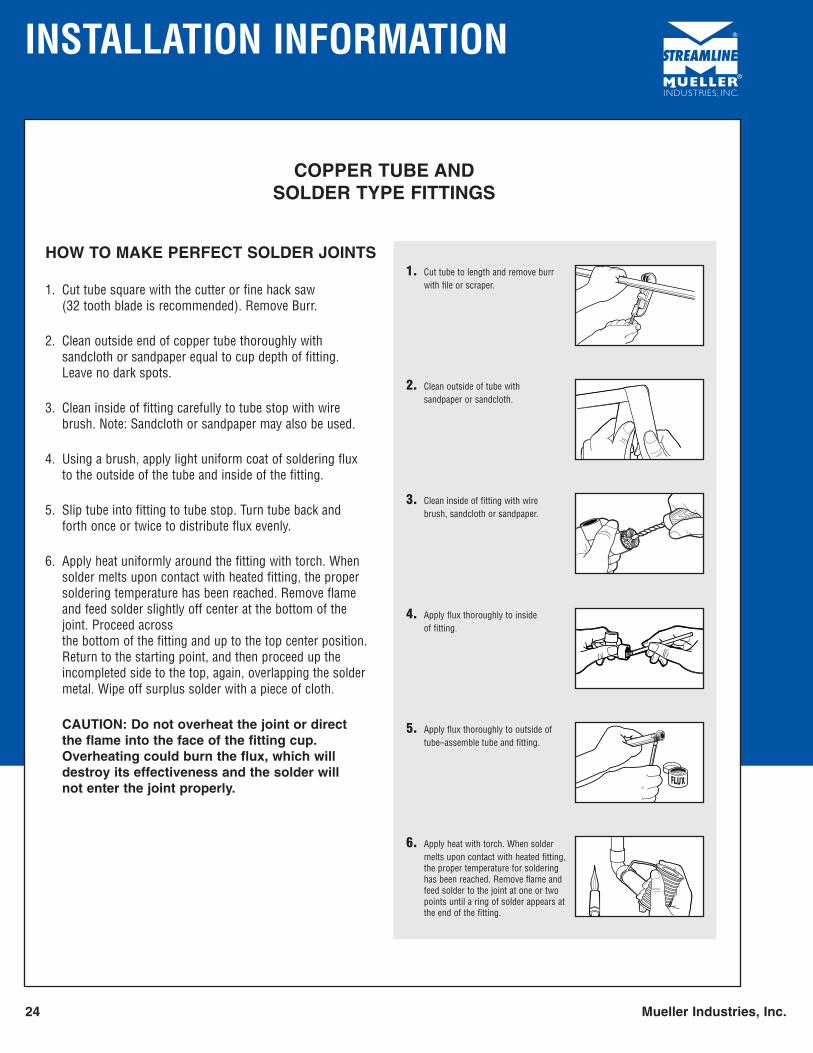
1. Cut tube to length and remove burrwith file or scraper.
2. Clean outside of tube with sandpaper or sandcloth.
3. Clean inside of fitting with wirebrush, sandcloth or sandpaper.
4. Apply flux thoroughly to inside of fitting.
5. Apply flux thoroughly to outside oftube–assemble tube and fitting.
6. Apply heat with torch. When soldermelts upon contact with heated fitting,the proper temperature for solderinghas been reached. Remove flame andfeed solder to the joint at one or twopoints until a ring of solder appears atthe end of the fitting.
COPPER TUBE ANDSOLDER TYPE FITTINGS
HOW TO MAKE PERFECT SOLDER JOINTS
1. Cut tube square with the cutter or fine hack saw(32 tooth blade is recommended). Remove Burr.
2. Clean outside end of copper tube thoroughly with sandcloth or sandpaper equal to cup depth of fitting. Leave no dark spots.
3. Clean inside of fitting carefully to tube stop with wirebrush. Note: Sandcloth or sandpaper may also be used.
4. Using a brush, apply light uniform coat of soldering flux to the outside of the tube and inside of the fitting.
5. Slip tube into fitting to tube stop. Turn tube back and forth once or twice to distribute flux evenly.
6. Apply heat uniformly around the fitting with torch. Whensolder melts upon contact with heated fitting, the propersoldering temperature has been reached. Remove flameand feed solder slightly off center at the bottom of thejoint. Proceed across the bottom of the fitting and up to the top center position.Return to the starting point, and then proceed up theincompleted side to the top, again, overlapping the soldermetal. Wipe off surplus solder with a piece of cloth.
CAUTION: Do not overheat the joint or direct the flame into the face of the fitting cup.Overheating could burn the flux, which willdestroy its effectiveness and the solder will not enter the joint properly.
FREQUENTLY ASKED QUESTIONS
Mueller Industries, Inc. 25
The following information may be helpful when a system is being designed. Mueller wrot copper solder joint pressure fittings can be used in some of the following applications:
1. What are some of the common system designs or applications where solder joint pressure fittings may be used?
Answer:• Plumbing of homes, high rise apartments, industrial, commercial and office buildings.• Underground water services.• Chilled water mains (Solder joint pressure fittings only).• Heating – For radiant panel and hydronic heating for snow melting systems.• Fuel Oil, L.P. and Natural Gas Services in accordance with local codes.• Nonflammable Medical Gas Systems per NFPA 99. (Health Care Facilities)• Air Conditioning and Refrigeration Systems.• Ground Source Heat Pump Systems.• Fire Sprinkler Systems.
2. Can you buy type K fittings?
Answer: No, the minimum wall for copper fittings are governed by ASME B16.22 andMSS SP-104 standards.
3. What can be done when a union leaks?
Answer: Assuming both male and female ends are not damaged or obstructed by a foreign material, it can be sealed by applying a light coat of bees wax.
4. Are Wrot copper fittings lead free?
Answer: Yes
5. Are Cast copper alloy solder joint pressure fittings lead free?
Answer: No, Cast fittings contain 7% lead.
TERMS AND CONDITIONS OF SALE
26 Mueller Industries, Inc.
THE FOLLOWING CONSTITUTE THE TERMS AND CONDITIONS OF SALE FOR ALLPRODUCTS MANUFACTURED, DISTRIBUTED AND/OR SOLD BY MUELLERINDUSTRIES, INC. OR ITS SUBSIDIARIES OR AFFILIATES (SELLER).
ACCEPTANCE OF SELLER'S OFFER TO SELL OR BUYER'S ORDER IS EXPRESSLYMADE CONDITIONAL ON BUYER'S ACCEPTANCE OF THE PROVISIONS STATEDHEREIN. BUYER'S ACCEPTANCE OF EACH SHIPMENT OF GOODS SHALL BEDEEMED TO BE AN ACCEPTANCE OF THE PROVISIONS HEREOF NOTWITHSTANDINGANY ACT OF SELLER, INCLUDING SHIPMENT, ACCEPTANCE OF PAYMENTS, ANDNOTWITHSTANDING ANY TERM OR CONDITION CONTAINED IN ANY FORM OFBUYER, AND ANY PROPOSAL FOR ADDITIONAL OR DIFFERENT TERMS OR ANYATTEMPT BY BUYER TO VARY ANY OF THE PROVISIONS HEREIN IS HEREBYDEEMED A MATERIAL ALTERATION AND REJECTED. THE PROVISIONS HEREINMAY NOT BE ADDED TO, MODIFIED, SUPERSEDED, OR ALTERED EXCEPT BY WRIT-TEN AGREEMENT OR MODIFICATION SIGNED BY AN OFFICER OF SELLER,NOTWITHSTANDING ANY TERMS WHICH MAY NOW OR IN THE FUTURE APPEARON BUYER'S FORMS OR COMMUNICATIONS, ALL OF WHICH ARE REJECTEDWITHOUT FURTHER ACTION OF SELLER.
NO PERSON (EXCEPT AN OFFICER OF SELLER) IS AUTHORIZED TO BIND SELLERTO ANY ORDER FOR ANY GOODS EXCEPT ACCORDING TO THE PROVISIONS HEREIN.
1. PRICES. All prices for SELLER's products are subject to change or withdrawal withoutnotice. Unless otherwise stated by SELLER, prices, terms of payment and pricing policies willbe those of the SELLER in effect at the time of shipment. SELLER reserves the right to makeprice changes within the periods of contracts, including installment contracts or blanket orders.The cost of packing and crating other than in accordance with the standards of SELLER mayconstitute an additional charge and may at SELLER's discretion be added to the sales price(s).SELLER also reserves the right to divide Buyer's order into separate shipments and to invoiceand otherwise treat each shipment as a separate contract subject to these Terms and Conditions.All sales and shipments are subject at all times to credit approval by SELLER.
2. TRANSPORTATION AND RISK OF LOSS. Unless otherwise agreed in advance in writingby SELLER, delivery of products hereunder shall be F.O.B. shipping point, with transportationexpenses paid by Buyer unless standard SELLER freight prepayment qualifications are met andthe risk of loss or damage to products in transit shall fall upon Buyer (whose responsibility itshall be to file claims with carrier at delivery to Buyer at Buyer's premises) upon delivery (a) toBuyer's designated representative, or (b) to a common carrier or other designated shipper (notincluding SELLER), whichever of the foregoing occurs earlier. SELLER in its discretion shallselect the appropriate transportation method and routing. All orders, unless otherwise agreed inwriting, are for shipment at SELLER's earliest convenience. Stated delivery dates are approximateand will be calculated from the date that SELLER has received all information necessary topermit SELLER to proceed with work immediately and without interruption. If any or allproducts are not delivered when ready due to the request of Buyer, SELLER reserves the rightto invoice Buyer at any time thereafter and to place such products in storage with all risk of lossor damage borne by Buyer and with all expenses and costs attributable thereto for the accountof Buyer, which shall be payable by Buyer upon submission of SELLER's invoices to Buyer.
3. DELAYS. SELLER shall not be liable for any delays in delivery due or resulting in wholeor in part from or made impossible or impractical by any cause beyond the control of SELLERincluding but not limited to fire, explosion, epidemics, accident, material and significant break-down, strike or labor disputes, adverse weather conditions, loss or damage in shipment, short-age or lack of materials, fuel or power, sale or transfer of manufacturing facilities, embargo, actsof God, acts (including delay or failure to act) of any governmental authority (de jure or defacto) or any other contingency or delay or failure or cause beyond SELLER's control. If, dueto any such occurrence, SELLER is unable to supply total demands for any goods specified,SELLER may, but shall not be obligated to, allocate production, inventory and deliveries (in anymanner fair and reasonable to the extent that goods are not special or unique) and will notify Buyerreasonably that there will be delay or nondelivery.
4. TAXES. All prices are exclusive of any applicable foreign or U.S.A. federal, state or localsales, use, excise or other taxes, which SELLER may be required to pay or collect, under anyexisting or future law, upon or with respect to the sale, delivery, storage, processing, use orconsumption of any of the products covered hereby, which shall be for the account of Buyer,who shall promptly pay the amount thereof to SELLER upon demand.
5. PAYMENT TERMS AND SECURITY INTEREST. Unless otherwise agreed in advance inwriting by SELLER, payment terms are 2% 30 days, net 45 days. All payments not made withinsuch time may be subject to a carrying charge of one percent per month on the unpaid balanceor the highest rate permitted by applicable law, whichever is the lesser. Until the entire amountdue hereunder is paid, SELLER reserves a security interest in all products sold, with all rights,privileges and remedies of a selling secured party in the jurisdiction to which the goods may beshipped or within which they may be kept at any time. In pursuance thereof, Buyer agrees totimely execute any documents which SELLER may request from time to time in order to givenotice of, perfect or otherwise give effect to the existence of said security interest.
6. FINANCIAL RESPONSIBILITY. If Seller has any reasonable doubt at any time as toBuyer’s financial condition and ability to perform, Seller, at its option, may (a) decline to makefurther shipments other than on a cash in advance basis or upon Buyer providing other securitysatisfactory to Seller, or (b) terminate this agreement.
7. RECEIVING AND INSPECTION. Any claim by Buyer based upon or relating to anyclaimed defect in the products ascertainable upon visual inspection thereof, including withoutlimitation any claim relating to size, type, quantity or shipping damage and the like, must be pre-sented to SELLER or its representative within fifteen (15) days following the date of receipt of theproduct by Buyer. Buyer's receipt of any product delivered hereunder shall be an unqualifiedacceptance, and a waiver by Buyer of any and all such claims with respect to such productunless Buyer gives SELLER notice of claim within fifteen (15) days after such receipt. Unlessotherwise agreed in advance in writing by SELLER, variations in the products as to composition,dimensions, quantity and the like shall be permissible and not cause for Buyer's rejection orrevocation if within prevailing industry (United States of America) standards. Buyer assumesall risk and liability for results.
8. TOOLING. Buyer will indemnify, defend and hold SELLER harmless from and against anyliability, damage, loss or expense arising from the use or handling of any tooling supplied ordesigned by Buyer from which products are to be cast or manufactured by SELLER.
9. PATENT INDEMNITY. SELLER agrees to protect, indemnify and hold harmless the Buyer,its successors, assigns, customers and users of its products against any liability, loss, damage orexpense whatsoever resulting from any infringement of any United States Letters Patent by anything, number, material, design, composition, or processing of SELLER's origin or practice
supplied by SELLER. With respect to any thing, number, material or design, composition, orprocessing, specified by Buyer and not of SELLER's origin or practice, BUYER agrees to saveSELLER harmless from any liability, loss damage or expense whatsoever resulting from anyinfringement of any United States Letters Patent arising out of SELLER's making, using or sellingthe same for or to BUYER in fulfillment of its orders or contracts. SELLER and BUYERseverally agree to notify the other in writing promptly of any charge of infringement made andof any suit brought in respect to such device or composition and to assume or tender to the otherthe full control of the defense or settlement of such suit in accordance herewith.
10. WARRANTY. Seller warrants only to Buyer that products furnished of Seller’s ownmanufacture will conform to prevailing (United States of America) industry standards as toquality, inspections, composition, quantity and type, and will be free from defects in workmanshipand materials for a period of one year from the date of receipt by Buyer of the products. Thiswarranty will not apply to damage resulting from normal wear, improper installation, misuse orneglect. Weight figures shown in Seller’s catalogue and price sheets, and documents of sale areapproximate only. Product is sold on a per unit basis not on a weight basis. Seller does notwarrant any aspect of product representation, installation, modifications or manufacturingcarried out by parties other than Seller and Buyer hereby indemnifies Seller for any loss, costor expense to which Seller may be exposed as a result of any such activities by Buyer or Buyer’scustomers. Seller’s sole obligation for failure to comply with this warranty will be, at itselection, to repair or replace the defective product where Buyer notifies Seller and such productis made available to Seller for inspection F.O.B. Seller’s facility or point of manufacture withinthe one year warranty period. Except to the extent that (1) descriptions of size, quality and type,which may appear on Seller invoices and other documents, and (2) statements of conformity ofproducts with specification of certain industry, government, or professional organizationsstandards, which may appear as product information disclosures in Seller’s literature anddocuments, may from time to time be construed to be express warranties, THIS WARRANTYIS IN LIEU OF AND EXCLUDES ALL OTHER WARRANTIES, EXPRESS OR IMPLIED,INCLUDING MERCHANTABILITY AND FITNESS FOR A PARTICULAR PURPOSE.
11. LIMITATION OF LIABILITY. Under no circumstances will Seller’s liability in theaggregate to Buyer under any legal theory, including without limitation, breach of contract orwarranty, or commission of any tort, including negligence and strict liability, or claims forindemnification, exceed the invoice price for the affected product. Buyer must commence anyaction at law or in equity against Seller within one year after the product is delivered to Buyer.Buyer will not have any recourse against Seller for any loss which reasonably could beprevented by cover or otherwise. Exceptions to Seller’s warranty and limitation of liabilityprovisions or waivers of the same granted by Seller will not constitute a precedent, default orwaiver of Seller’s rights to enforce such provisions in whole or in part in the future. SELLERWILL NOT BE LIABLE TO ANY PERSON FOR ANY INDIRECT, SPECIAL, INCIDENTAL,CONSEQUENTIAL OR OTHER DAMAGES OF ANY KIND WHATSOEVER, WHETHERANY CLAIM OR POTENTIAL CLAIM IS BASED UPON THEORIES OF CONTRACT,NEGLIGENCE, OR TORT AND INCLUDING WITHOUT LIMITATION, SELLER WILLHAVE NO LIABILITY FOR SHIPPING CHARGES, LABOR, INSTALLATION, COSTS ORANY OTHER LOSSES OR EXPENSES RELATED TO OR ASSOCIATED WITH THEINSPECTION, REPAIR OR REPLACEMENT OF THE WARRANTED PRODUCTS.
12. DEFAULT. Buyer will be in default if (a) Buyer fails to pay Seller any amount when dueunder this agreement, (b) Buyer otherwise fails for a period of five days after receiving writtennotice from Seller to fulfill or perform any provisions of this agreement, (c) Buyer becomesinsolvent or bankrupt, or a petition is filed voluntarily or involuntarily and not dismissed within30 days of filing, or (d) Buyer makes a general assignment for the benefit of its creditors, or areceiver is appointed, or a substantial part of Buyer’s assets are attached or seized under legalprocess and not released within 30 days thereafter.
Upon buyer’s default, Seller may, at its option, without prejudice to any of its other rights andremedies, and without demand for payments past due, (a) make shipments subject to receipt ofcash in advance, (b) terminate this agreement and declare immediately due and payable theobligations of Buyer for goods previously shipped, notwithstanding any other provision in theseterms and conditions, (c) demand reclamation, or (d) suspend any further deliveries until thedefault is corrected, without releasing Buyer from its obligations under this agreement. In anyevent, Buyer will remain liable for all loss and damage sustained by Seller because of Buyer’sdefault.
13. OTHER. (a) SELLER accepts no responsibility to BUYER or to any person claiming by orthrough BUYER, for compliance with any statute, governmental rule or regulation madeapplicable to this contract by reason of BUYER's intended use of the products unless SELLERhas received from BUYER prior timely written notification of such statute, rule or regulationand has accepted the same by a separate writing signed by an officer of SELLER.
(b) SELLER's forbearance or failure to enforce any of these conditions as set forth herein or toexercise any right accruing from any default of BUYER shall not affect, impair or waiveSELLER's right if such default continues or if any subsequent default of BUYER occurs.
(c) The provisions herein constitute the entire agreement between BUYER and SELLER and noterms or conditions other than those stated herein and no agreement or understanding oral orwritten in any way purporting to modify these conditions shall be binding on SELLER unlesshereafter made in writing and signed by an officer of SELLER. All orders are subject toacceptance at SELLER's offices. This agreement shall be construed in accordance with thelaws of Tennessee and any disputes arising under these terms and conditions, and the orders towhich they pertain, shall be brought exclusively in Shelby County, Tennessee.
(d) The provisions of this agreement shall be considered severable. In the event that any of theprovisions, or portions or applications thereof, of this agreement are held to be unenforceable orinvalid by any court of competent jurisdiction, all remaining portions shall remain in full forceand effect in accordance with the spirit of this agreement.
(e) The rights and obligations of BUYER and SELLER hereunder shall not be assigned to anythird party without the prior written consent of the other party.
(f) ACCEPTANCE OF THE PRODUCTS SOLD HEREUNDER SHALL CONSTITUTEASSENT TO THESE CONDITIONS AND SELLER HEREBY OBJECTS TO AND REJECTSANY AND ALL ADDITIONAL OR DIFFERENT TERMS PROPOSED BY BUYER,WHETHER CONTAINED IN BUYER'S PURCHASING OR SHIPPING RELEASE FORMSOR ELSEWHERE. ALL PROPOSALS, NEGOTIATIONS, AND REPRESENTATIONS, IFANY, MADE PRIOR AND WITH REFERENCE HERETO ARE MERGED HEREIN, ANDANY PROPOSED ADDITIONS, MODIFICATIONS, DELETIONS OR CHANGES NOT INSEPARATE WRITINGS SIGNED BY AN OFFICER OF SELLER ARE REJECTEDWITHOUT FURTHER ACTION BY SELLER.
Customers acknowledge that the above terms and conditions of sale shall pertain to each and every order placed with Mueller Industries, Inc.
HOMEOWNER LIMITED WARRANTY
Mueller Industries, Inc. 27
RESIDENTIAL COPPER PLUMBING PRODUCTS
WHAT THE WARRANTY TERMS MEAN
In this warranty, “Manufacturer” refers to Mueller Industries, Inc. or its subsidiaries, which manufactures the Product, and any personor company that assumes its obligation under this warranty. “Homeowner” means the owner of the residential building in the UnitedStates in which the Product has been installed and also means any succeeding owner during the original warranty term. “Product”means the copper water tube and/or copper or brass fittings manufactured by the Manufacturer for the residential building market inthe United States. Manufacturer warrants only Products it has manufactured and does not warrant Products of any other company.
DATE THE WARRANTY BEGINS
The warranty begins on the date of the new home purchase, or in the case of home additions or renovations, on the date the installation is completed. The warranty is transferable to succeeding Homeowners for the remainder of the original warranty term, inwhich case the date the warranty begins shall continue without change.
WHAT IS COVERED
The Manufacturer warrants to the Homeowner for a period of 50 years from the date the warranty begins that its properly installedProduct will be free of failure as a result of defects in material or workmanship in manufacturing the Product.
WHAT THE MANUFACTURER WILL DO FOR YOU
As long as (1) such a failure occurs within 50 years from the date the warranty begins and (2) the Homeowner promptly notifies theManufacturer of the Product of that failure by contacting it through its 800 phone number listed below, the Manufacturer will correctthat failure by repairing or replacing the Product within a reasonable time, without charge. This warranty is limited to the cost ofrepairing or replacing the Product, including installation.
WHAT IS NOT COVERED: DISCLAIMER OF LIABILITY FOR CONSEQUENTIAL AND OTHER DAMAGES
The Manufacturer does NOT warrant against failure:1. of any product, parts or systems that it has not manufactured;2. if the Product is used for purposes other than residential plumbing applications;3. caused by, contributed in whole or in part by or resulting from any of the following;
(a) improper installation;(b) abuse, such as, without limitation, vandalism;(c) natural disasters, such as, without limitation, flooding, windstorm and lightning;(c) attachments or modifications to the Product that the Manufacturer did not authorize;(e) external causes, where external, physical or chemical qualities produce damage to the Product, such as without
limitation, aggressive water or an unsuitable or hostile environment; or(f) any other cause beyond the Manufacturer’s control.
The Manufacturer shall NOT be liable under any circumstances for any other direct or any indirect, incidental or consequential damages of any kind.
THIS IS THE ONLY WARRANTY
THIS WARRANTY IS THE ONLY WARRANTY FOR THE PRODUCT PROVIDED BY THE MANUFACTURER, AND IS AND SHALL BE INLIEU OF ANY AND ALL OTHER WARRANTIES, EXPRESS OR IMPLIED, INCLUDING BUT NOT LIMITED TO AN IMPLIED WARRANTYOF MERCHANTABILITY, AND OF ALL OTHER OBLIGATIONS OR LIABILITIES ON THE PART OF THE MANUFACTURER. NONE OF THEMANUFACTURER’S EMPLOYEES, AND NO OTHER PERSON OR BUSINESS, IS AUTHORIZED TO MAKE ANY OTHER WARRANTY ONTHE MANUFACTURER’S BEHALF COVERING THE PRODUCT.
THIS WARRANTY GIVES YOU SPECIFIC LEGAL RIGHTS, AND YOU MAY ALSO HAVE OTHER RIGHTS WHICH VARY FROM STATE TOSTATE. SOME STATES DO NOT ALLOW THE EXCLUSION OR LIMITATION OF INCIDENTAL OR CONSEQUENTIAL DAMAGES, SO THEABOVE LIMITATION OR EXCLUSION MAY NOT APPLY TO YOU.
Mueller Industries, Inc.800-348-8464Memphis, TN

NOTES
28 Mueller Industries, Inc.