Embed Size (px)
Citation preview
8/6/2019 MTW82manual Detector de Metal
http://slidepdf.com/reader/full/mtw82manual-detector-de-metal 1/6
TW-82
Operating ManualF I S H E R R E S E A R C H L A B O R A T O R Y
DIGITAL LINE TRACER
MTW82 101510
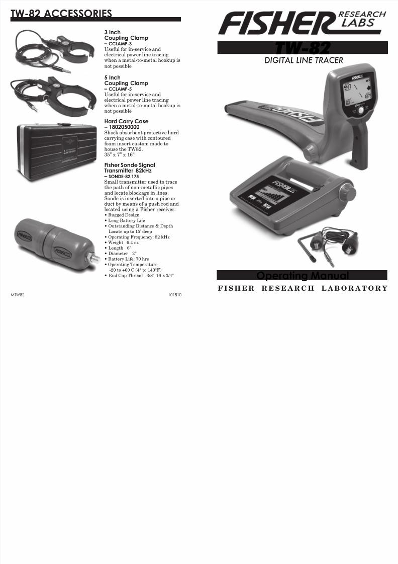
3 InchCoupling Clamp
– CCLAMP-3
Useul or in-service andelectrical power line tracingwhen a metal-to-metal hookup isnot possible
5 InchCoupling Clamp
– CCLAMP-5
Useul or in-service andelectrical power line tracingwhen a metal-to-metal hookup isnot possible Hard Carry Case
– 1802050000Shock absorbent protective hard
carrying case with contouredoam insert custom made tohouse the TW82.35” x 7” x 16”
Fisher Sonde SignalTransmitter 82kHz
– SONDE-82.175Small transmitter used to tracethe path o non-metallic pipesand locate blockage in lines.Sonde is inserted into a pipe orduct by means o a push rod and
located using a Fisher receiver.• Rugged Design
• Long Battery Lie
• Outstanding Distance & Depth
Locate up to 15’ deep
• Operating Frequency: 82 kHz
• Weight 6.4 oz
• Length 6”
• Diameter 2”
• Battery Lie: 70 hrs
• Operating Temperature
-20 to +60 C (4° to 140°F)
• End Cap Thread 3/8”-16 x 3/4”
TW-82 ACCESSORIES
8/6/2019 MTW82manual Detector de Metal
http://slidepdf.com/reader/full/mtw82manual-detector-de-metal 2/6
Introduction ..........................................................................pg. 3
Transmitter ...........................................................................pg. 4-6
Receiver ..................................................................................pg. 7-9
Specifcations ........................................................................pg. 10
Warranty .................................................................................pg. 11
Accessories .............................................................................pg. 12
CONTENTS
11
Q U A L I T YFisherdetectorsarerenownedfortheirquality.
EachdetectorishandcraftedintheUSAwithpride
P E R F O R M A N C ETheworldwideundergroundutilityindustryreliesonFisher.
Ourinstrumentsaredurable,dependableandlocatedeeper.
R E P U T A T I O NFisherproducedthefirstpatentedmetaldetectorin1931.Forover80years,theFisherlogohasbeenamarkofexcellence.
2 - YEAR LIMITED WARRANTYProof of purchase is required to make a claim under this warranty.
NOTE TO CUSTOMERS OUTSIDE THE U.S.A.Thiswarrantymayvaryinothercountries,checkwithyour
distributorfordetails.Factorywarrantyfollowsthechannelofdistribution.
Warrantydoesnotcovershippingcosts.
S E R V I C EShould you have any questions or problems, contact:
FISHER RESEARCH LABORATORY1465-HHenryBrennan,ElPaso,Texas79936
Tel1800-685-5050Fax915-225-0336www.fisherlab.comemail:[email protected]
AccordingtoFCCpart15.21ChangesorModificationsmadetothisdevicenotexpresslyapprovedbythepartyresponsibleforcompliancecouldvoid
theusersauthoritytooperatethisequipment.
Nottobeusedwithconductivetracingcableslongerthan6.5’(1.98m)

8/6/2019 MTW82manual Detector de Metal
http://slidepdf.com/reader/full/mtw82manual-detector-de-metal 3/6
INTRODUCTION
1
3
TheTW-82DigitalLineTracercomponentsincludeaTransmitter,Receiver,ground-rodassembly,carryingcase(softoroptionalhardcase)andanoperator’smanual.The TW-82 isa singlefrequencylinetracer.
The TW82 is an active locating line tracer. There are three
locating methods that an operator can use to trace a utility.
1. The conductive method is the preerred method, as a strong
signal is transmitted directly through the utility line. A
conductive trace is accomplished by making a direct electrical
connection to the utility with a clamp.
2. When a direct electrical connection is not available, but the
operator has some knowledge o where one point o the utility
may be, the transmitter can be placed on the ground over
the utility. With this inductive tracing method, the signal is
transmitted through the ground and couples magnetically on to
utilities in close proximity.
3. A third method is also inductive, but uses the optional coupling
clamp. A coupling clamp can be used when a utility is exposed,
but a direct electrical connection is not possible. By tting the
coupling clamp around the utility, the signal transmits through
the air and couples magnetically on to the utility.
Never make direct contact with electrical or communication lines
that are in service. To trace such lines in service, perorm an
inductive trace, either with or without the coupling clamp.
10
SPECIFICATIONS
TRANSMITTER
RECEIVERFrequency ........................................ 82.175 kHz
Let/Right Guidance ........................Audible and visual
Azimuth Indicator ........................... Visual
Over-Target Indicator .....................Visual and audible
Battery Status .................................VisualSignal Strength Indicator ...............Numeric display & audible
Signal Current Measurement ........ Numeric display, automatic
Depth Measurement .......................Numeric display, automatic
Battery Type .................................... Two D-cell batteries (included)
Battery Lie .....................................60 hours, approximate
Weight, with batteries .....................3.60 lbs
Fisher Research Laboratory does not warrant suitability to specifc use. Fisher
Research Laboratory shall in no event be liable or any direct, incidental,
consequential or indirect damages.
Output Frequency ............................82.175 kHz
Output Power (nominal) ..................Normal Setting = 0.25 watt
High Setting = 1.0 watt
Conductive Tracing ..........................2 to 3,000 ohms, normal power-6dB
Magnetic Strength ...........................2 to 8,000 ohms, high power-6dB
Inductive Tracing .............................15 Vm2, normal power
Magnetic Strength ...........................25 Vm2, high power
Battery Type .....................................Four D-cell batteries (included)
Battery Lie ......................................Over 100 hours in normal power mode
Weight, with batteries......................4 lbs
Ingress Protection Rating ................IP65 (stands up to water jets)
Operating Temperature Range ........-4ºF to 140ºF (-20ºC to +60ºC)
Relative Humidity ............................0 to 95% noncondensing
Shipping Weight (packaged) ............17.5 lbs
Field Carry Weight, w/accessories ...15.5 lbs*
*Includes Carry Case, Batteries, Ground Rod and Conductive Tracing Cables
ENVIRONMENTAL
.....................
......................
8/6/2019 MTW82manual Detector de Metal
http://slidepdf.com/reader/full/mtw82manual-detector-de-metal 4/6
94
TW-82 TRANSMITTER
TW-82 Transmitter
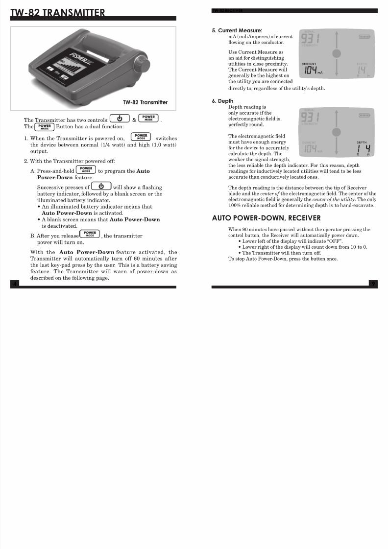
The Transmitter has two controls: & .
The Button has a dual unction:
1. When the Transmitter is powered on, switches
the device between normal (1/4 watt) and high (1.0 watt)
output.
2. With the Transmitter powered o:
A. Press-and-hold to program the Auto
Power-Down eature.
Successive presses o will show a fashing
battery indicator, ollowed by a blank screen or the
illuminated battery indicator.• An illuminated battery indicator means that
Auto Power-Down is activated.
• A blank screen means that Auto Power-Down
is deactivated.
B. Ater you release , the transmitter
power will turn on.
With the Auto Power-Down eature activated, the
Transmitter will automatically turn o 60 minutes ater
the last key-pad press by the user. This is a battery saving
eature. The Transmitter will warn o power-down asdescribed on the ollowing page.
5. Current Measure:mA (miliAmperes) o currentfowing on the conductor.
Use Current Measure asan aid or distinguishing
utilities in close proximity.
The Current Measure willgenerally be the highest on
the utility you are connected
directly to, regardless o the utility’s depth.
6. DepthDepth reading is
only accurate i theelectromagnetic eld isperectly round.
The electromagnetic eldmust have enough energy
or the device to accuratelycalculate the depth. Theweaker the signal strength,
the less reliable the depth indicator. For this reason, depthreadings or inductively located utilities will tend to be lessaccurate than conductively located ones.
The depth reading is the distance between the tip o Receiverblade and the center of the electromagnetic eld. The center o theelectromagnetic eld is generally the center of the utility. The only
100% reliable method or determining depth is to hand-excavate.
AUTO POWER-DOWN, RECEIVER
When 90 minutes have passed without the operator pressing thecontrol button, the Receiver will automatically power down.
• Lower let o the display will indicate “OFF”.• Lower right o the display will count down rom 10 to 0.
• The Transmitter will then turn o.To stop Auto Power-Down, press the button once.
TW-82 RECEIVER
8/6/2019 MTW82manual Detector de Metal
http://slidepdf.com/reader/full/mtw82manual-detector-de-metal 5/6
58
TW-82 TRANSMITTER
WARNING:Donothandleoutputleadsunlesspowerisoff.ELECTRIC SHOCK HAZARD:Servicingtobeperformedbyqualifiedpersonnelonly.
NEVERconnectconductivecablestoanenergizedpowerline.
Low Battery Power-Down Warning
When the Transmitter batteries are near the end o theiruseul lie, the Transmitter will warn the operator beoreshutting down.
Five minutes beore shutting down, the Transmitter will
alternately stop and start transmitting at approximately one-second intervals. The operator using the Receiver, even at adistance rom the Transmitter, will notice the signal turningon and o beore the power turns o completely.
Accessory Output
1. Flip up the black protective cover to expose the AccessoryOutput.
2. Plug in the Cable Jack or conductive tracing.
When the conductive tracing cable is connected, Signal
Current will be displayed. The Signal Current Bar Graphshows the quality o the connection.
Automatic Load Impedance Matching adjusts output toprovide ull rated power over a wide range o loads (e.g.utility types and conditions). It is tolerant o both dry(high resistance) and shunted (low resistance) groundconnections.
The Transmitter has a built-in antenna or inductivelocating. When the Cable Jack is not connected, the inductiveantenna automatically engages and begins transmitting.
When locating inductively, the Signal Current Bar Graphwill not be displayed, as there is no conductive trace load tobe measured.
PITCH INCREASES
AS YOU APPROACH THE UTILITY
HIGHEST PITCH & VOLUME
DIRECTLY OVER UTILITY
CONSTANT
PITCH BEYOND 45°
CONSTANT
PITCH BEYOND 45°
45°
VOLUME DECREASES WITH DISTANCE FROM UTILITY
TW-82 RECEIVER
Display - Continued
2. Battery Strength: When battery liedeclines to less than 1 hour (estimated)o operation the battery indicator outlinewill be illuminated with no segments.When the batteries reach the end o theiruseul lie, the screen will go blank and thebattery icon will fash beore the Receiver shuts o. Expect about
60 hours o battery lie rom a set o two D-cell alkaline batteries.
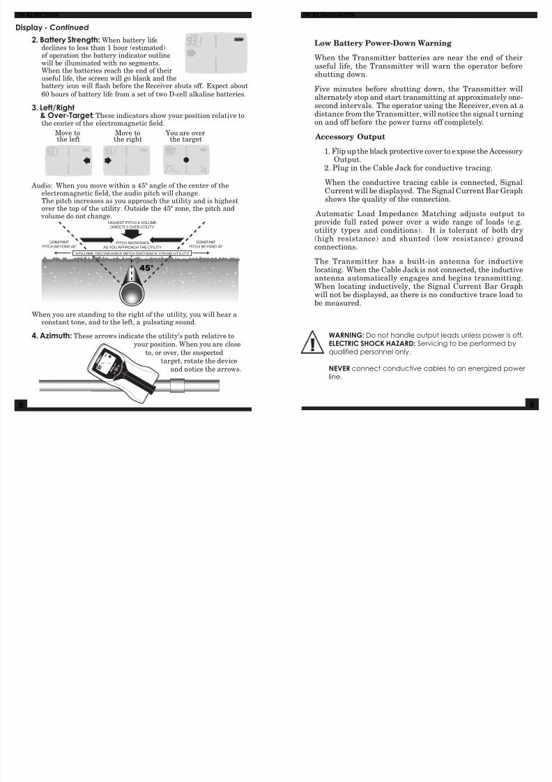
3. Left/Right& Over-Target: These indicators show your position relative tothe center o the electromagnetic eld.
Move to Move to You are overthe let the right the target
Audio: When you move within a 45º angle o the center o the
electromagnetic eld, the audio pitch will change.The pitch increases as you approach the utility and is highestover the top o the utility. Outside the 45º zone, the pitch and volume do not change.
When you are standing to the right o the utility, you will hear aconstant tone, and to the let, a pulsating sound.
4. Azimuth: These arrows indicate the utility’s path relative toyour position. When you are close
to, or over, the suspectedtarget, rotate the device
and notice the arrows.
8/6/2019 MTW82manual Detector de Metal
http://slidepdf.com/reader/full/mtw82manual-detector-de-metal 6/6
6
TW-82 RECEIVER
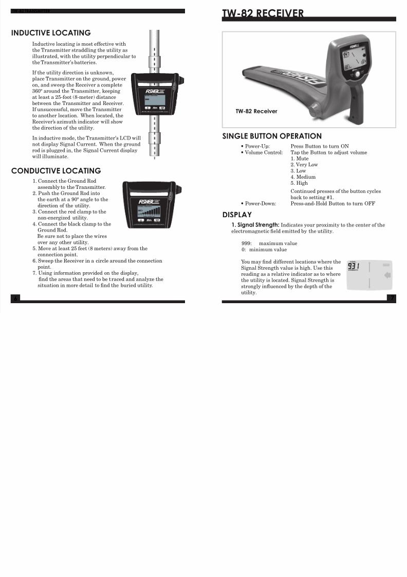
TW-82 Receiver
SINGLE BUTTON OPERATION
• Power-Up: Press Button to turn ON
• Volume Control: Tap the Button to adjust volume1. Mute2. Very Low
3. Low4. Medium5. High
Continued presses o the button cycles
back to setting #1.• Power-Down: Press-and-Hold Button to turn OFF
DISPLAY1. Signal Strength: Indicates your proximity to the center o the
electromagnetic eld emitted by the utility.
999: maximum value
0: minimum value
You may nd dierent locations where the
Signal Strength value is high. Use thisreading as a relative indicator as to wherethe utility is located. Signal Strength is
strongly infuenced by the depth o theutility.
7
INDUCTIVE LOCATING
Inductive locating is most eective withthe Transmitter straddling the utility as
illustrated, with the utility perpendicular tothe Transmitter’s batteries.
I the utility direction is unknown,place Transmitter on the ground, power
on, and sweep the Receiver a complete360º around the Transmitter, keepingat least a 25-oot (8-meter) distance
between the Transmitter and Receiver.I unsuccessul, move the Transmitterto another location. When located, the
Receiver’s azimuth indicator will showthe direction o the utility.
In inductive mode, the Transmitter’s LCD will
not display Signal Current. When the groundrod is plugged in, the Signal Current displaywill illuminate.
CONDUCTIVE LOCATING
1. Connect the Ground Rod
assembly to the Transmitter.2. Push the Ground Rod into
the earth at a 90º angle to the
direction o the utility.
3. Connect the red clamp to thenon-energized utility.
4. Connect the black clamp to theGround Rod.Be sure not to place the wires
over any other utility.5. Move at least 25 eet (8 meters) away rom the
connection point.
6. Sweep the Receiver in a circle around the connectionpoint.
7. Using inormation provided on the display,
nd the areas that need to be traced and analyze the
situation in more detail to nd the buried utility.
TW-82 TRANSMITTER