Embed Size (px)
Citation preview
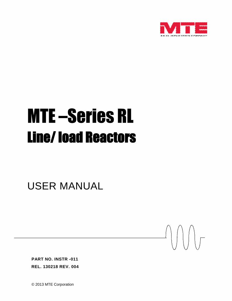
MTE –Series RLLine/ load Reactors
USER MANUAL
PART NO. INSTR -011
REL. 130218 REV. 004
© 2013 MTE Corporation

Data subject to change without notice 2 of 32 INSTR-011 REL. 130218 REV. 004See www.mtecorp.com for current data and CAD drawings
Important User Information
NOTICE
MTE Series RL Line/Load Reactors are components designed to improve the reliability ofadjustable frequency drives, DC drives and a wide variety of other types of powerelectronic equipment. In addition they provide limited input line current harmonicmitigation and aid in long lead protection for inverter fed motors. Note: (See MTEharmonic filters and motor protection products for guaranteed results.) MTE reactors areavailable in a large number of current ratings and a variety of inductance values. Thesuitability of a line/load reactor for a specific application must therefore be ultimatelydetermined by the customer. In no event will MTE Corporation assume responsibility orliability for any direct or consequential damages resulting from the use or application ofreactors. Nor will MTE Corporation assume patent liability with respect to the use ofinformation, circuits or equipment described in this instruction manual.
This manual includes recently redesigned performance enhanced reactors. These reactors arephysically smaller and weigh less than the reactors they replace. Enhanced reactors have basemounting brackets with additional slotted holes to accommodate past mounting hole centers. Youmay uses your existing drill pattern or choose the new layout. The tables contained in this manualreflect historical mounting dimensions for previous reactors.
This document supports computer searches and is best viewed with Adobe Acrobat™PDF viewer (6 or 7). Click links are incorporated throughout the document to speedupdocument navigation.

MTE AC Line / Load ReactorsUser Manual
Data subject to change without notice 3 of 32 INSTR-011 REL. 130218 Rev.004See www.mtecorp.com for current data and CAD drawings
Table of Contents
IMPORTANT USER INFORMATION..........................................................................................2
TABLE OF CONTENTS .............................................................................................................3
IMPORTANT SAFETY INFORMATION......................................................................................4
INTRODUCTION ........................................................................................................................5
MODEL NUMBER CODES.........................................................................................................6
SPARE PARTS ..........................................................................................................................7
LUG OPTION DETAILS: ............................................................................................................8
PRODUCT SPECIFICATIONS .................................................................................................10
DE-RATING CURVES ..............................................................................................................13
DIMENSION REFERENCE.......................................................................................................14
MOUNTING COMPATIBILITY..................................................................................................15
MECHANICAL DETAILS OPEN REACTORS..........................................................................16
NEMA1 MECHANICAL DATA..................................................................................................18
RECOMMENDED CONDUIT ENTRY FOR FLOOR MOUNTED...............................................20
ENCLOSURE DIMINSIONS .....................................................................................................21
TECHNICAL DATA ..................................................................................................................25
INSTALLATION INSTRUCTIONS ............................................................................................27
POWER WIRING CONNECTION .............................................................................................28
TYPICAL CONNECTION DIAGRAMS .....................................................................................29
SEQUENCE OF OPERATION..................................................................................................30
STARTUP.................................................................................................................................31

MTE AC Line / Load ReactorsUser Manual
Data subject to change without notice 4 of 32 INSTR-011 REL. 130218 REV. 004See www.mtecorp.com for current data and CAD drawings
IMPORTANT SAFETY INFORMATION
WARNING
ONLY A QUALIFIED ELECTRICIAN CAN CARRY OUT THE ELECTRICALINSTALLATION OF LINE/LOAD REACTORS
WARNING
High voltage is used in the operation of line/load reactors. Use Extreme caution to avoid contact with highvoltage when operating, installing or repairing equipment containing line/load reactors
INJURY OR DEATH MAY RESULT IF SAFETY PRECAUTIONS ARE NOT OBSERVED.
Line/load reactors are used in conjunction with inverters, or other electrical equipment that may feedbacklethal voltages. Follow the safety instructions in the equipment used with the reactor in addition to thesafety instruction in this manual.
WARNING
The opening of the branch circuit protective device may be an indication that a fault current has beeninterrupted. To reduce the risk of fire or electrical shock, line/load reactors should be examined andreplaced if damaged.
WARNING
An upstream disconnect/protection device must be used as required by the National Electrical Code(NEC).
WARNING
Even if the upstream disconnect/protection device is open, a drive or inverter down stream of theline/load reactor may feed back high voltage to the reactor. The inverter or drive safety instructionsmust be followed.
INJURY OR DEATH MAY RESULT IF THE DRIVE SAFETY PRECAUTIONS ARE NOTOBSERVED.
WARNING
The frame of line/load reactors must be grounded at least at one of the reactor’s mounting holes.
WARNING
Only spare parts obtained from MTE Corporation or an authorized MTE distributor can be used
MTE AC Line / Load ReactorsUser Manual
Data subject to change without notice 5 of 32 INSTR-011 REL. 130218 REV. 004See www.mtecorp.com for current data and CAD drawings
INTRODUCTION
This manual was specifically developed toassist in the installation, interconnection andoperation of MTE Corporation Series RLLine/Load Reactors
This manual is intended for use bypersonnel experienced in the operation andmaintenance of electronic drives, invertersand similar types of power electronicequipment. Because of the high voltagesrequired by the equipment connected toline/load reactors and the potential dangerspresented by rotating machinery, it isessential that all personnel involved in theoperation and maintenance of line/loadreactors know and practice the necessarysafety precautions for this type ofequipment. Personnel should read andunderstand the instructions contained in thismanual before installing, operating orservicing line/load reactors and the drive towhich the reactor is connected.
Upon Receipt of a Reactor:
MTE Line/load Reactors have beensubjected to demanding factory tests beforeshipment. Carefully inspect the shippingcontainer for damage that may haveoccurred in transit. Then unpack the filterand carefully inspect for any signs ofdamage. Save the shipping container forfuture transport of the reactor.
In the event of damage, please contactand file a claim with the freight carrierinvolved immediately.
If the equipment is not going to be put intoservice upon receipt, cover and store thereactor in a clean, dry location. Afterstorage, ensure that the equipment is dryand that no condensation has accumulatedon the reactor before applying power.
Repair/Exchange Procedure
MTE Corporation requires a ReturnedMaterial Authorization Number before it canaccept any reactors that qualify for return orrepair. If problems or questions arise duringinstallation, setup, or operation of the filter,please call us for assistance at:
Phone: 1-262-253-8200FAX: 1-262-253-8222
MTE AC Line / Load ReactorsUser Manual
Data subject to change without notice 6 of 32 INSTR-011 REL. 130218 REV.004See www.mtecorp.com for current data and CAD drawings
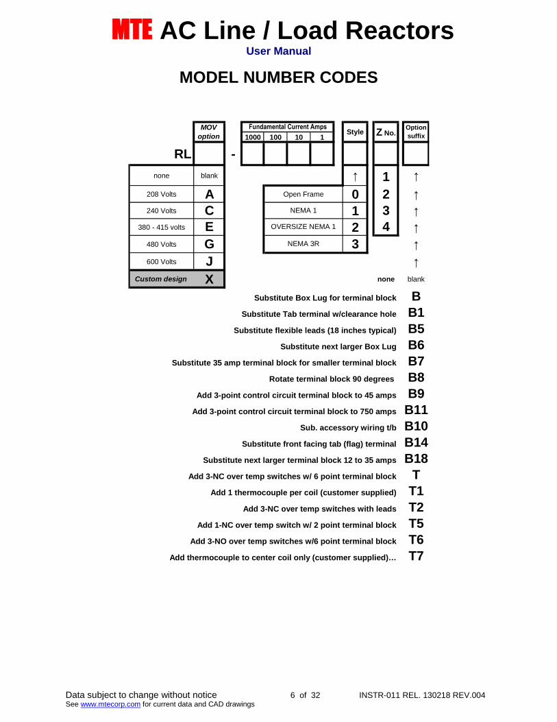
MODEL NUMBER CODES
1000 100 10 1
RL -
none blank ↑ 1 ↑
208 Volts A 0 2 ↑
240 Volts C 1 3 ↑
380 - 415 volts E 2 4 ↑
480 Volts G 3 ↑
600 Volts J ↑
Custom design X none blank
Substitute Box Lug for terminal block BSubstitute Tab terminal w/clearance hole B1
Substitute flexible leads (18 inches typical) B5Substitute next larger Box Lug B6
Substitute 35 amp terminal block for smaller terminal block B7Rotate terminal block 90 degrees B8
Add 3-point control circuit terminal block to 45 amps B9Add 3-point control circuit terminal block to 750 amps B11
Sub. accessory wiring t/b B10
Substitute front facing tab (flag) terminal B14Substitute next larger terminal block 12 to 35 amps B18
Add 3-NC over temp switches w/ 6 point terminal block TAdd 1 thermocouple per coil (customer supplied) T1
Add 3-NC over temp switches with leads T2Add 1-NC over temp switch w/ 2 point terminal block T5
Add 3-NO over temp switches w/6 point terminal block T6
Add thermocouple to center coil only (customer supplied)… T7
Style Z No.Option
suffix
MOV
option
Fundamental Current Amps
NEMA 1
OVERSIZE NEMA 1
NEMA 3R
Open Frame
MTE AC Line / Load ReactorsUser Manual
Data subject to change without notice 7 of 32 INSTR-011 REL. 130218 REV.004See www.mtecorp.com for current data and CAD drawings
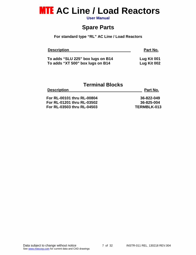
Spare Parts
For standard type “RL” AC Line / Load Reactors
Description Part No.
To adds “SLU 225” box lugs on B14 Lug Kit 001To adds “XT 500” box lugs on B14 Lug Kit 002
Terminal BlocksDescription Part No.
For RL-00101 thru RL-00804 36-822-049For RL-01201 thru RL-03502 36-825-004For RL-03503 thru RL-04503 TERMBLK-013

MTE AC Line / Load ReactorsUser Manual
Data subject to change without notice 8 of 32 INSTR-011 REL. 130218 REV.004See www.mtecorp.com for current data and CAD drawings
LUG OPTION DETAILS:
“B1” Terminal Modification “B14” Terminal Modification
“B8” Terminal Modification
“SLU” Lug Option
Wire range: 2 - 0000Wire range: 00 – 500 mcm
MTE AC Line / Load ReactorsUser Manual
Data subject to change without notice 9 of 32 INSTR-011 REL. 130218 REV.004See www.mtecorp.com for current data and CAD drawings
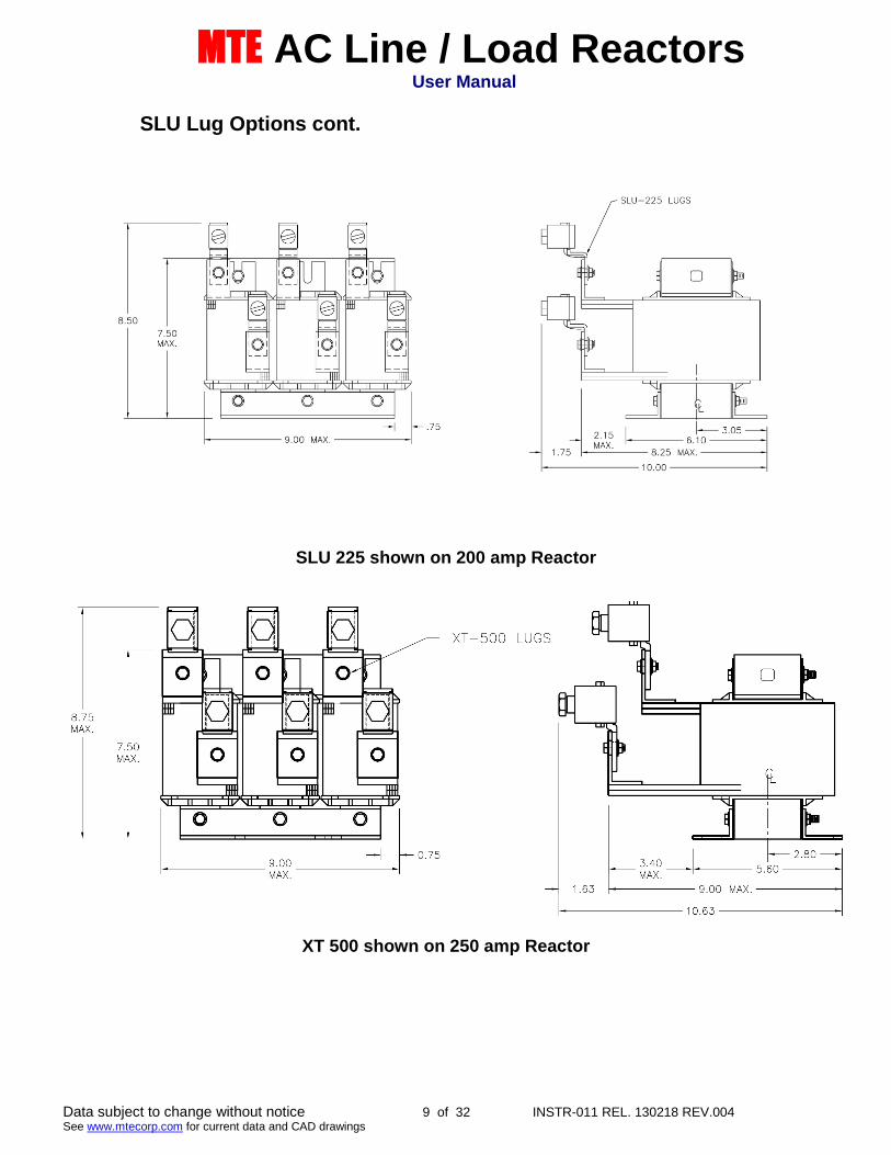
SLU Lug Options cont.
SLU 225 shown on 200 amp Reactor
XT 500 shown on 250 amp Reactor

MTE AC Line / Load ReactorsUser Manual
Data subject to change without notice 10 of 32 INSTR-011 REL. 130218 REV.004See www.mtecorp.com for current data and CAD drawings
PRODUCT SPECIFICATIONS
Standard impedance values 1-1/2%, 2, 3%, 4%, 5% available
Impedance basis Reactor fundamental current rating
Service Factor(Continuous)Reactors rated 1 to 750 Amps 150% of fundamental ratingReactors rated above 750 Amps 125% of fundamental rating minimum
Note: Select reactor based on fundamental currentrating
Overload Rating 200% of fundamental for 30 minutes
300% of fundamental for 1 minute
Maximum system voltage 600 Volts ( units with terminal blocks)690 Volts (units with box lugs or tab terminals)
Maximum switching frequency 20 KHz
Insulation system Class N (200° C)
Temperature riseOpen or enclosed reactors 135° C (average)
Ambient temperatureOpen or enclosed reactors 45° C (maximum)
Altitude (maximum) 1000 meters
Fundamental frequencyLine or Load 50/60 Hz
Approvals: CE, UL-508, CSA C22.2
Inductance curve (typical) 100% at 100% current100% at 150% current50% at 350% current (minimum)
Inductance tolerance +/- 10%
Impregnation: High Bond Strength “Solvent less” Epoxy, 200° CUL94HB recognized
Dielectric Strength 3000 volts rms (4243 volts peak)
dv/dt Protection Meets NEMA MG-1, part 31 (same as inverter dutymotors)
Protection: Open reactors with terminal blocks through 45 ampsmeet IP20
MTE AC Line / Load ReactorsUser Manual
Data subject to change without notice 11 of 32 INSTR-011 REL. 130218 REV.004See www.mtecorp.com for current data and CAD drawings
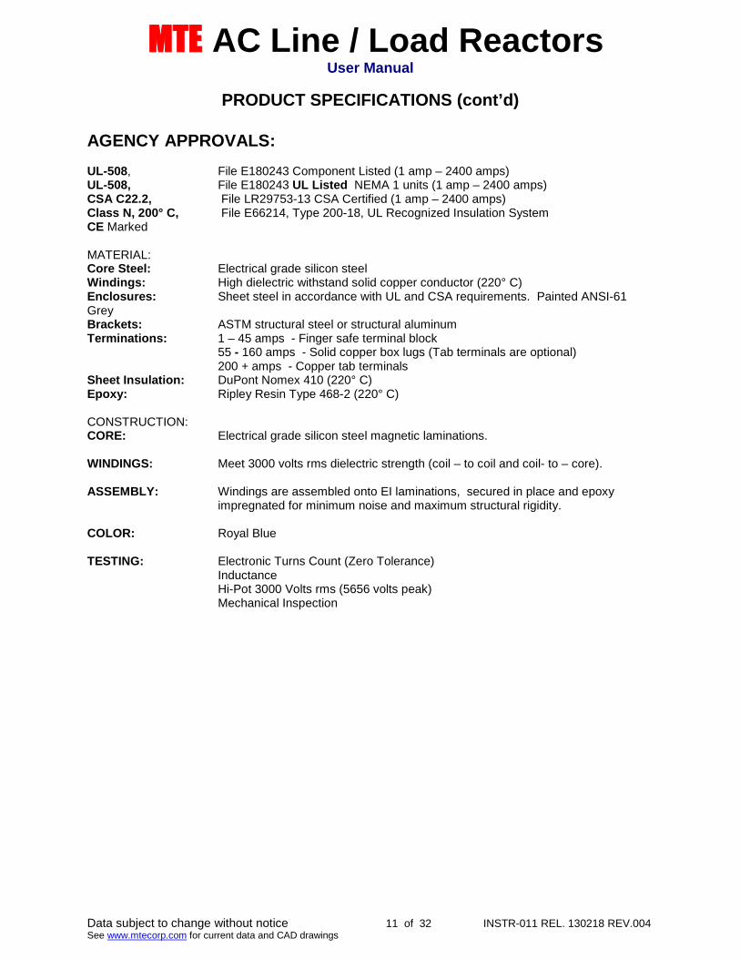
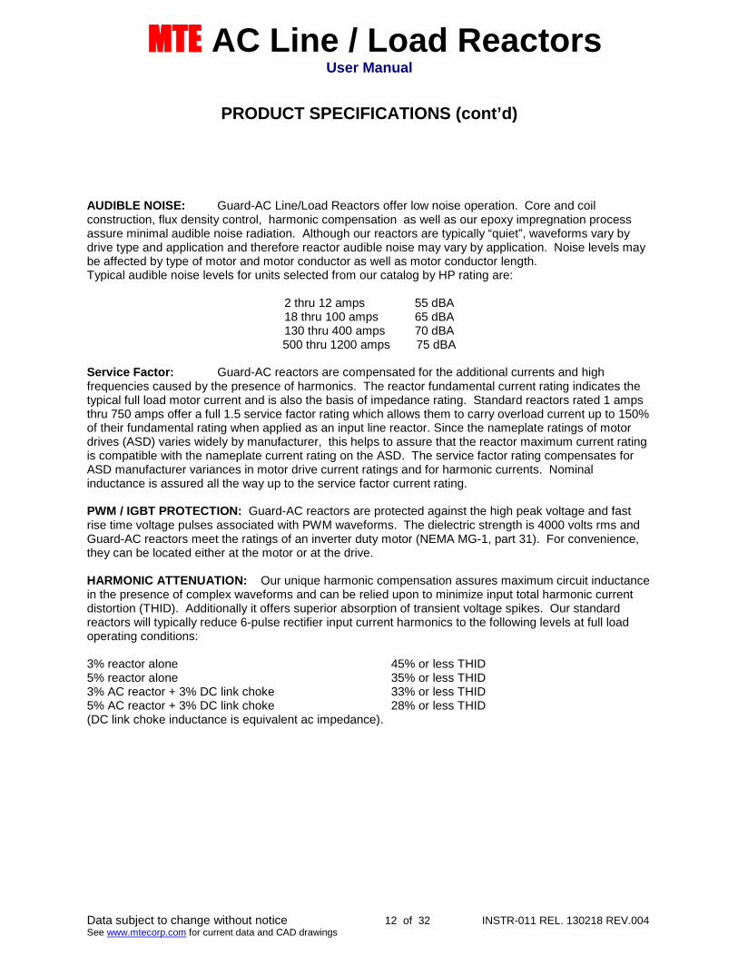
PRODUCT SPECIFICATIONS (cont’d)
AGENCY APPROVALS:
UL-508, File E180243 Component Listed (1 amp – 2400 amps)UL-508, File E180243 UL Listed NEMA 1 units (1 amp – 2400 amps)CSA C22.2, File LR29753-13 CSA Certified (1 amp – 2400 amps)Class N, 200° C, File E66214, Type 200-18, UL Recognized Insulation SystemCE Marked
MATERIAL:Core Steel: Electrical grade silicon steelWindings: High dielectric withstand solid copper conductor (220° C)Enclosures: Sheet steel in accordance with UL and CSA requirements. Painted ANSI-61GreyBrackets: ASTM structural steel or structural aluminumTerminations: 1 – 45 amps - Finger safe terminal block
55 - 160 amps - Solid copper box lugs (Tab terminals are optional)200 + amps - Copper tab terminals
Sheet Insulation: DuPont Nomex 410 (220° C)Epoxy: Ripley Resin Type 468-2 (220° C)
CONSTRUCTION:CORE: Electrical grade silicon steel magnetic laminations.
WINDINGS: Meet 3000 volts rms dielectric strength (coil – to coil and coil- to – core).
ASSEMBLY: Windings are assembled onto EI laminations, secured in place and epoxyimpregnated for minimum noise and maximum structural rigidity.
COLOR: Royal Blue
TESTING: Electronic Turns Count (Zero Tolerance)InductanceHi-Pot 3000 Volts rms (5656 volts peak)Mechanical Inspection
MTE AC Line / Load ReactorsUser Manual
Data subject to change without notice 12 of 32 INSTR-011 REL. 130218 REV.004See www.mtecorp.com for current data and CAD drawings
PRODUCT SPECIFICATIONS (cont’d)
AUDIBLE NOISE: Guard-AC Line/Load Reactors offer low noise operation. Core and coilconstruction, flux density control, harmonic compensation as well as our epoxy impregnation processassure minimal audible noise radiation. Although our reactors are typically “quiet”, waveforms vary bydrive type and application and therefore reactor audible noise may vary by application. Noise levels maybe affected by type of motor and motor conductor as well as motor conductor length.Typical audible noise levels for units selected from our catalog by HP rating are:
2 thru 12 amps 55 dBA18 thru 100 amps 65 dBA130 thru 400 amps 70 dBA500 thru 1200 amps 75 dBA
Service Factor: Guard-AC reactors are compensated for the additional currents and highfrequencies caused by the presence of harmonics. The reactor fundamental current rating indicates thetypical full load motor current and is also the basis of impedance rating. Standard reactors rated 1 ampsthru 750 amps offer a full 1.5 service factor rating which allows them to carry overload current up to 150%of their fundamental rating when applied as an input line reactor. Since the nameplate ratings of motordrives (ASD) varies widely by manufacturer, this helps to assure that the reactor maximum current ratingis compatible with the nameplate current rating on the ASD. The service factor rating compensates forASD manufacturer variances in motor drive current ratings and for harmonic currents. Nominalinductance is assured all the way up to the service factor current rating.
PWM / IGBT PROTECTION: Guard-AC reactors are protected against the high peak voltage and fastrise time voltage pulses associated with PWM waveforms. The dielectric strength is 4000 volts rms andGuard-AC reactors meet the ratings of an inverter duty motor (NEMA MG-1, part 31). For convenience,they can be located either at the motor or at the drive.
HARMONIC ATTENUATION: Our unique harmonic compensation assures maximum circuit inductancein the presence of complex waveforms and can be relied upon to minimize input total harmonic currentdistortion (THID). Additionally it offers superior absorption of transient voltage spikes. Our standardreactors will typically reduce 6-pulse rectifier input current harmonics to the following levels at full loadoperating conditions:
3% reactor alone 45% or less THID5% reactor alone 35% or less THID3% AC reactor + 3% DC link choke 33% or less THID5% AC reactor + 3% DC link choke 28% or less THID(DC link choke inductance is equivalent ac impedance).
MTE AC Line / Load ReactorsUser Manual
Data subject to change without notice 13 of 32 INSTR-011 REL. 130218 REV.004See www.mtecorp.com for current data and CAD drawings
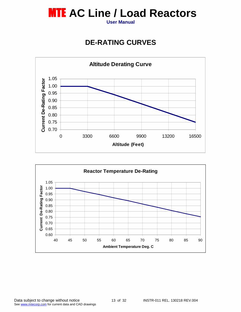
DE-RATING CURVES
Altitude Derating Curve
0.70
0.75
0.80
0.85
0.90
0.95
1.00
1.05
0 3300 6600 9900 13200 16500
Altitude (Feet)
Cu
rren
tD
e-R
ati
ng
Facto
r
Reactor Temperature De-Rating
0.60
0.65
0.70
0.75
0.80
0.85
0.90
0.95
1.00
1.05
40 45 50 55 60 65 70 75 80 85 90
Ambient Temperature Deg. C
Cu
rre
nt
De
-Ra
tin
gF
ac
tor

MTE AC Line / Load ReactorsUser Manual
Data subject to change without notice 14 of 32 INSTR-011 REL. 130218 REV.004See www.mtecorp.com for current data and CAD drawings
Dimension ReferenceOpen Type
Visit the MTE web for reactor detail drawings www.mtecorp.com
Dimensions A, B, C show overall spacing allowancesUse dimension D and E for mounting pattern
See “Mechanical Details Table” for dimensional data
THISIS THE CATOLOG.

MTE AC Line / Load ReactorsUser Manual
Data subject to change without notice 15 of 32 INSTR-011 REL. 130218 REV.004See www.mtecorp.com for current data and CAD drawings
Mounting Compatibility
MTE AC Line / Load ReactorsUser Manual
Data subject to change without notice 16 of 32 INSTR-011 REL. 130218 REV.004See www.mtecorp.com for current data and CAD drawings
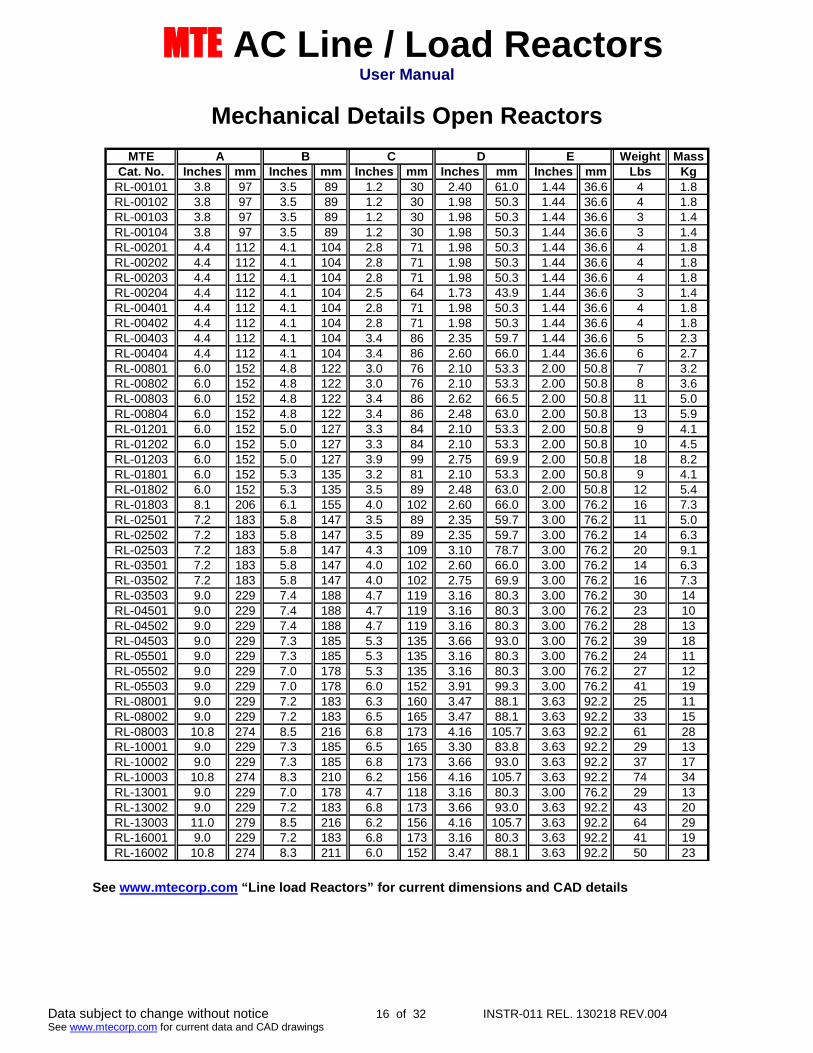
Mechanical Details Open Reactors
MTE Weight MassCat. No. Inches mm Inches mm Inches mm Inches mm Inches mm Lbs Kg
RL-00101 3.8 97 3.5 89 1.2 30 2.40 61.0 1.44 36.6 4 1.8RL-00102 3.8 97 3.5 89 1.2 30 1.98 50.3 1.44 36.6 4 1.8RL-00103 3.8 97 3.5 89 1.2 30 1.98 50.3 1.44 36.6 3 1.4RL-00104 3.8 97 3.5 89 1.2 30 1.98 50.3 1.44 36.6 3 1.4RL-00201 4.4 112 4.1 104 2.8 71 1.98 50.3 1.44 36.6 4 1.8RL-00202 4.4 112 4.1 104 2.8 71 1.98 50.3 1.44 36.6 4 1.8RL-00203 4.4 112 4.1 104 2.8 71 1.98 50.3 1.44 36.6 4 1.8RL-00204 4.4 112 4.1 104 2.5 64 1.73 43.9 1.44 36.6 3 1.4RL-00401 4.4 112 4.1 104 2.8 71 1.98 50.3 1.44 36.6 4 1.8RL-00402 4.4 112 4.1 104 2.8 71 1.98 50.3 1.44 36.6 4 1.8RL-00403 4.4 112 4.1 104 3.4 86 2.35 59.7 1.44 36.6 5 2.3RL-00404 4.4 112 4.1 104 3.4 86 2.60 66.0 1.44 36.6 6 2.7RL-00801 6.0 152 4.8 122 3.0 76 2.10 53.3 2.00 50.8 7 3.2RL-00802 6.0 152 4.8 122 3.0 76 2.10 53.3 2.00 50.8 8 3.6RL-00803 6.0 152 4.8 122 3.4 86 2.62 66.5 2.00 50.8 11 5.0RL-00804 6.0 152 4.8 122 3.4 86 2.48 63.0 2.00 50.8 13 5.9RL-01201 6.0 152 5.0 127 3.3 84 2.10 53.3 2.00 50.8 9 4.1RL-01202 6.0 152 5.0 127 3.3 84 2.10 53.3 2.00 50.8 10 4.5RL-01203 6.0 152 5.0 127 3.9 99 2.75 69.9 2.00 50.8 18 8.2RL-01801 6.0 152 5.3 135 3.2 81 2.10 53.3 2.00 50.8 9 4.1RL-01802 6.0 152 5.3 135 3.5 89 2.48 63.0 2.00 50.8 12 5.4RL-01803 8.1 206 6.1 155 4.0 102 2.60 66.0 3.00 76.2 16 7.3RL-02501 7.2 183 5.8 147 3.5 89 2.35 59.7 3.00 76.2 11 5.0RL-02502 7.2 183 5.8 147 3.5 89 2.35 59.7 3.00 76.2 14 6.3RL-02503 7.2 183 5.8 147 4.3 109 3.10 78.7 3.00 76.2 20 9.1RL-03501 7.2 183 5.8 147 4.0 102 2.60 66.0 3.00 76.2 14 6.3RL-03502 7.2 183 5.8 147 4.0 102 2.75 69.9 3.00 76.2 16 7.3RL-03503 9.0 229 7.4 188 4.7 119 3.16 80.3 3.00 76.2 30 14RL-04501 9.0 229 7.4 188 4.7 119 3.16 80.3 3.00 76.2 23 10RL-04502 9.0 229 7.4 188 4.7 119 3.16 80.3 3.00 76.2 28 13RL-04503 9.0 229 7.3 185 5.3 135 3.66 93.0 3.00 76.2 39 18RL-05501 9.0 229 7.3 185 5.3 135 3.16 80.3 3.00 76.2 24 11RL-05502 9.0 229 7.0 178 5.3 135 3.16 80.3 3.00 76.2 27 12RL-05503 9.0 229 7.0 178 6.0 152 3.91 99.3 3.00 76.2 41 19RL-08001 9.0 229 7.2 183 6.3 160 3.47 88.1 3.63 92.2 25 11RL-08002 9.0 229 7.2 183 6.5 165 3.47 88.1 3.63 92.2 33 15RL-08003 10.8 274 8.5 216 6.8 173 4.16 105.7 3.63 92.2 61 28RL-10001 9.0 229 7.3 185 6.5 165 3.30 83.8 3.63 92.2 29 13RL-10002 9.0 229 7.3 185 6.8 173 3.66 93.0 3.63 92.2 37 17RL-10003 10.8 274 8.3 210 6.2 156 4.16 105.7 3.63 92.2 74 34RL-13001 9.0 229 7.0 178 4.7 118 3.16 80.3 3.00 76.2 29 13RL-13002 9.0 229 7.2 183 6.8 173 3.66 93.0 3.63 92.2 43 20RL-13003 11.0 279 8.5 216 6.2 156 4.16 105.7 3.63 92.2 64 29RL-16001 9.0 229 7.2 183 6.8 173 3.16 80.3 3.63 92.2 41 19RL-16002 10.8 274 8.3 211 6.0 152 3.47 88.1 3.63 92.2 50 23
EA B C D
See www.mtecorp.com “Line load Reactors” for current dimensions and CAD details

MTE AC Line / Load ReactorsUser Manual
Data subject to change without notice 17 of 32 INSTR-011 REL. 130218 REV.004See www.mtecorp.com for current data and CAD drawings
Mechanical Data Open Type Cont.
MTE Weight MassCat. No. Inches mm Inches mm Inches mm Inches mm Inches mm Lbs Kg
RL-20001B14 9.0 229 7.5 191 7.3 185 4.16 105.7 3.63 92.2 38 17RL-20002B14 9.0 229 7.5 191 8.3 211 4.41 112.0 3.63 92.2 54 24RL-20003B14 10.8 274 8.3 211 10.0 254 5.91 150.1 3.63 92.2 100 45RL-25001B14 9.0 229 7.5 191 9.0 229 4.19 106.4 3.63 92.2 47 21RL-25002B14 10.8 274 8.5 216 9.0 229 5.16 131.1 4.60 116.8 80 36RL-25003B14 14.4 366 11.2 284 10.3 262 5.82 147.8 4.60 116.8 125 57RL-32001B14 10.8 274 9.0 229 8.3 211 5.16 131.1 4.60 116.8 80 36RL-32002B14 10.8 274 9.0 229 10.0 254 5.88 149.4 4.60 116.8 102 46RL-32003B14 14.4 366 11.3 286 10.5 267 7.13 181.1 4.60 116.8 160 73RL-40001B14 10.8 274 10.0 254 10.0 254 5.16 131.1 4.60 116.8 84 38RL-40002B14 15.0 381 11.3 286 11.5 292 6.76 171.7 4.60 116.8 118 54RL-40003B14 14.4 366 11.3 286 12.5 318 7.26 184.4 4.60 116.8 149 68RL-50001 10.8 274 9.0 229 10.5 267 5.50 139.7 4.60 116.8 93 42RL-50002 14.4 366 11.5 292 11.5 292 6.76 171.7 4.60 116.8 118 54RL-50003 14.4 366 11.5 292 13.3 338 9.76 247.9 4.60 116.8 210 95RL-60001 14.4 366 11.5 292 10.0 254 5.26 133.6 4.60 116.8 120 54RL-60002 14.4 366 11.3 286 12.0 305 8.00 203.2 4.60 116.8 175 79RL-60003 14.4 366 11.3 286 15.0 381 9.26 235.2 4.60 116.8 270 122RL-75001 14.4 366 11.5 292 11.0 279 6.63 168.4 7.20 182.9 140 63RL-75002 14.4 366 11.5 292 12.5 318 8.01 203.5 7.20 182.9 190 86RL-75003 14.4 366 14.5 368 14.0 356 9.26 235.2 7.20 182.9 265 120RL-85001 20.3 514 16.8 425 13.0 330 7.60 193.0 7.20 182.9 285 129RL-85002 22.0 559 16.8 425 13.0 330 8.00 203.2 7.20 182.9 370 168RL-85003 22.5 572 16.8 427 18.0 457 9.00 228.6 7.20 182.9 452 205RL-100001 21.6 549 16.8 425 11.0 279 7.26 184.4 7.20 182.9 320 145RL-100002 20.3 514 16.8 425 13.0 330 8.50 215.9 7.20 182.9 408 185RL-100003 20.3 514 16.8 425 15.0 381 10.76 273.3 7.20 182.9 589 267RL-120001 22.5 572 17.0 432 13.0 330 11.00 279.4 7.20 182.9 425 193RL-120002 21.5 546 17.0 432 20.0 508 10.76 273.3 7.20 182.9 440 200RL-120003 16.8 427 17.0 432 18.5 470 11.00 279.4 7.20 182.9 560 254RL-140001 22.0 559 17.0 432 22.0 559 11.00 279.4 7.20 182.9 500 227RL-140002 19.0 483 17.0 432 19.0 483 11.00 279.4 7.20 182.9 525 238RL-140003 22.0 559 17.0 432 22.0 559 11.00 279.4 7.20 182.9 850 385RL-150001 22.0 559 17.0 432 22.0 559 11.00 279.4 7.20 182.9 635 288RL-150002 16.9 429 17.0 432 16.0 406 11.00 279.4 7.20 182.9 675 306RL-150003 22.0 559 17.0 432 22.0 559 11.00 279.4 7.20 182.9 900 408RL-180001 22.0 559 17.0 432 22.0 559 11.00 279.4 7.20 182.9 700 317RL-180002 22.0 559 17.0 432 22.0 559 10.38 263.7 7.20 182.9 860 390RL-180003 22.0 559 17.0 432 22.0 559 11.00 279.4 7.20 182.9 1090 494RL-210001 24.0 610 18.0 457 24.0 610 11.00 279.4 7.20 182.9 800 363RL-210002 24.0 610 18.0 457 24.0 610 11.00 279.4 7.20 182.9 970 440
EA B C D
See www.mtecorp.com “Line load Reactors” for current dimensions and CAD details
MTE AC Line / Load ReactorsUser Manual
Data subject to change without notice 18 of 32 INSTR-011 REL. 130218 REV.004See www.mtecorp.com for current data and CAD drawings
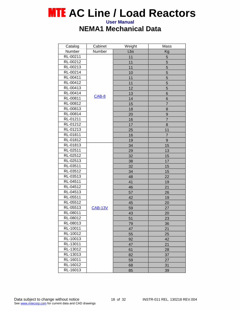
NEMA1 Mechanical Data
Catalog Cabinet Weight Mass
Number Number Lbs Kg
RL-00211
CAB-8
11 5RL-00212 11 5RL-00213 11 5RL-00214 10 5RL-00411 11 5RL-00412 11 5RL-00413 12 5RL-00414 13 6RL-00811 14 6RL-00812 15 7RL-00813 18 8RL-00814 20 9RL-01211 16 7RL-01212 17 8RL-01213 25 11RL-01811 16 7RL-01812 19 9RL-01813
CAB-13V
34 15RL-02511 29 13RL-02512 32 15RL-02513 38 17RL-03511 32 15RL-03512 34 15RL-03513 48 22RL-04511 41 19RL-04512 46 21RL-04513 57 26RL-05511 42 19RL-05512 45 20RL-05513 59 27RL-08011 43 20RL-08012 51 23RL-08013 79 36RL-10011 47 21RL-10012 55 25RL-10013 92 42RL-13011 47 21RL-13012 61 28RL-13013 82 37RL-16011 59 27RL-16012 68 31RL-16013 85 39

MTE AC Line / Load ReactorsUser Manual
Data subject to change without notice 19 of 32 INSTR-011 REL. 130218 REV.004See www.mtecorp.com for current data and CAD drawings
MECHANICAL DATA NEMA 1 Cont.
Catalog Cabinet Weight Mass
Number Number Lbs Kg
RL-20011B14
CAB-13V
56 25RL-20012B14 72 33RL-20013B14 118 54RL-25011B14 65 30RL-25012B14
CAB-17V
107 49RL-25013B14 152 69RL-32011B14 107 49RL-32012B14 129 59RL-32013B14 187 85RL-40011B14 111 50RL-40012B14 145 66RL-40013B14 176 80
RL-50011 120 54RL-50012
CAB-26C
262 119RL-50013 354 161RL-60011 264 120RL-60012 319 145RL-60013 414 188RL-75011
CAB-30B
299 136RL-75012 349 158RL-75013 424 192RL-85011 444 202RL-85012 529 240RL-85013 611 277RL-100011 479 217RL-100012 567 257RL-100013 748 340RL-120011 584 265RL-120012 599 272RL-120013 719 326RL-140011
CAB-42C
803 365RL-140012 828 376RL-140013 1153 523RL-150011 938 426RL-150012 978 444RL-150013 1203 546RL-180011 1003 455RL-180012 1163 528RL-180013 1393 632RL-210011 1103 501RL-210012 1273 578RL-210013 1573 714
MTE AC Line / Load ReactorsUser Manual
Data subject to change without notice 20 of 32 INSTR-011 REL. 130218 REV.004See www.mtecorp.com for current data and CAD drawings
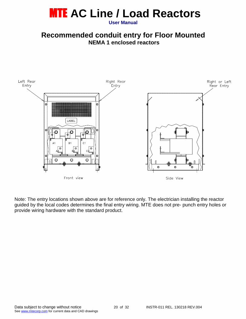
Recommended conduit entry for Floor MountedNEMA 1 enclosed reactors
Note: The entry locations shown above are for reference only. The electrician installing the reactorguided by the local codes determines the final entry wiring. MTE does not pre- punch entry holes orprovide wiring hardware with the standard product.

MTE AC Line / Load ReactorsUser Manual
Data subject to change without notice 21 of 32 INSTR-011 REL. 130218 REV.004See www.mtecorp.com for current data and CAD drawings
ENCLOSURE DIMINSIONS
CAB-8
CAB-12C

MTE AC Line / Load ReactorsUser Manual
Data subject to change without notice 22 of 32 INSTR-011 REL. 130218 REV.004See www.mtecorp.com for current data and CAD drawings
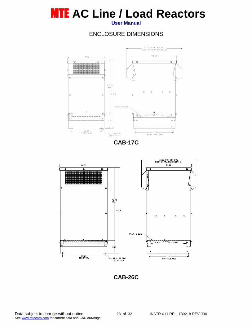
ENCLOSURE DIMENSIONS
CAB-13V
CAB-17V
MTE AC Line / Load ReactorsUser Manual
Data subject to change without notice 23 of 32 INSTR-011 REL. 130218 REV.004See www.mtecorp.com for current data and CAD drawings
ENCLOSURE DIMENSIONS
CAB-17C
CAB-26C
MTE AC Line / Load ReactorsUser Manual
Data subject to change without notice 24 of 32 INSTR-011 REL. 130218 REV.004See www.mtecorp.com for current data and CAD drawings
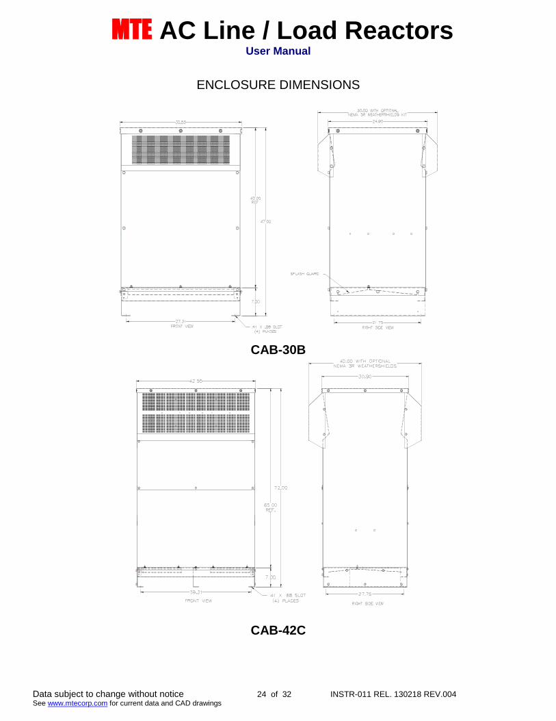
ENCLOSURE DIMENSIONS
CAB-30B
CAB-42C

MTE AC Line / Load ReactorsUser Manual
Data subject to change without notice 25 of 32 INSTR-011 REL. 130218 REV.004See www.mtecorp.com for current data and CAD drawings
TECHNICAL DATA
Catalog Watts Loss Wire Range Terminal Torque Ind. Fund Max
Number (watts) (AWG) (in – lbs) mH Amps Amps
RL-00101 13.5 22 – 10 4.5 100 1 1.5
RL-00102 12.8 22 – 10 4.5 50 1 1.5
RL-00103 11.9 22 – 10 4.5 36 1 1.5
RL-00104 9.6 22 – 10 4.5 18 1 1.5
RL-00201 8 22 – 10 4.5 12 2 3
RL-00202 12 22 – 10 4.5 20 2 3
RL-00203 16 22 – 10 4.5 32 2 3
RL-00204 11 22 – 10 4.5 6 2 3
RL-00401 15 22 – 10 4.5 3 4 6
RL-00402 20 22 – 10 4.5 6.5 4 6
RL-00403 20 22 – 10 4.5 9 4 6
RL-00404 21 22 – 10 4.5 12 4 6
RL-00801 20 22 – 10 4.5 1.5 8 12
RL-00802 29 22 – 10 4.5 3 8 12
RL-00803 26 22 – 10 4.5 5 8 12
RL-00804 28 22 – 10 4.5 7.5 8 12
RL-01201 26 14 - 6 16 1.25 12 18
RL-01202 31 14 - 6 16 2.5 12 18
RL-01203 41 14 - 6 16 4.2 12 18
RL-01801 36 14 - 6 16 0.8 18 27
RL-01802 43 14 - 6 16 1.5 18 27
RL-01803 43 14 - 6 16 2.5 18 27
RL-02501 48 14 - 6 16 0.5 25 37.5
RL-02502 52 14 - 6 16 1.2 25 37.5
RL-02503 61 14 - 6 16 1.8 25 37.5
RL-03501 49 14 - 6 16 0.4 35 52.5
RL-03502 54 14 - 6 16 0.8 35 52.5
RL-03503 54 18 – 4 16 1.2 35 52.5
RL-04501 54 18 – 4 16 0.3 45 67.5
RL-04502 62 18 – 4 16 0.7 45 67.5
RL-04503 65 18 – 4 16 1.2 45 67.5
RL-05501 64 6 – 0 6-4(45) & 2-0(50) 0.25 55 82.5
RL-05502 67 6 – 0 6-4(45) & 2-0(50) 0.5 55 82.5
RL-05503 71 6 – 0 6-4(45) & 2-0(50) 0.85 55 82.5
RL-08001 82 6 – 0 6-4(45) & 2-0(50) 0.2 80 120
RL-08002 86 6 – 0 6-4(45) & 2-0(50) 0.4 80 120
RL-08003 96 6 – 0 6-4(45) & 2-0(50) 0.7 80 120
RL-10001 94 6 – 0 6-4(45) & 2-0(50) 0.15 100 150
RL-10002 84 6 – 0 6-4(45) & 2-0(50) 0.3 100 150
RL-10003 108 6 – 0 6-4(45) & 2-0(50) 0.45 100 150
RL-13001 108 2 – 0000 150 0.1 130 195
RL-13002 180 2 – 0000 150 0.2 130 195
RL-13003 128 2 – 0000 150 0.3 130 195
RL-16001 116 2 – 0000 150 0.075 160 240
MTE AC Line / Load ReactorsUser Manual
Data subject to change without notice 26 of 32 INSTR-011 REL. 130218 REV.004See www.mtecorp.com for current data and CAD drawings
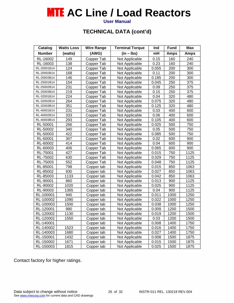
TECHNICAL DATA (cont’d)
Catalog Watts Loss Wire Range Terminal Torque Ind Fund Max
Number (watts) (AWG) (in – lbs) mH Amps Amps
RL-16002 149 Copper Tab Not Applicable 0.15 160 240RL-16003 138 Copper Tab Not Applicable 0.23 160 240
RL-20001B14 124 Copper Tab Not Applicable 0.055 200 300RL-20002B14 168 Copper Tab Not Applicable 0.11 200 300RL-20003B14 146 Copper Tab Not Applicable 0.185 200 300RL-25001B14 154 Copper Tab Not Applicable 0.045 250 375RL-25002B14 231 Copper Tab Not Applicable 0.09 250 375RL-25003B14 219 Copper Tab Not Applicable 0.15 250 375RL-32001B14 224 Copper Tab Not Applicable 0.04 320 480RL-32002B14 264 Copper Tab Not Applicable 0.075 320 480RL-32003B14 351 Copper Tab Not Applicable 0.125 320 480RL-40001B14 231 Copper Tab Not Applicable 0.03 400 600RL-40002B14 333 Copper Tab Not Applicable 0.06 400 600RL-40003B14 293 Copper Tab Not Applicable 0.105 400 600RL-50001 266 Copper Tab Not Applicable 0.025 500 750RL-50002 340 Copper Tab Not Applicable 0.05 500 750RL-50003 422 Copper Tab Not Applicable 0.085 500 750RL-60001 307 Copper Tab Not Applicable 0.02 600 900RL-60002 414 Copper Tab Not Applicable 0.04 600 900RL-60003 406 Copper Tab Not Applicable 0.065 600 900RL-75001 427 Copper Tab Not Applicable 0.015 750 1125RL-75002 630 Copper Tab Not Applicable 0.029 750 1125RL-75003 552 Copper Tab Not Applicable 0.048 750 1125RL-85001 798 Copper tab Not Applicable 0.015 850 1063RL-85002 930 Copper tab Not Applicable 0.027 850 1063RL-85003 1133 Copper tab Not Applicable 0.042 850 1063RL-90001 860 Copper tab Not Applicable 0.013 900 1125RL-90002 1020 Copper tab Not Applicable 0.025 900 1125RL-90003 1365 Copper tab Not Applicable 0.04 900 1125RL-100001 940 Copper tab Not Applicable 0.011 1000 1250RL-100002 1090 Copper tab Not Applicable 0.022 1000 1250RL-100003 1500 Copper tab Not Applicable 0.038 1000 1250RL-120001 980 Copper tab Not Applicable 0.009 1200 1500RL-120002 1130 Copper tab Not Applicable 0.019 1200 1500RL-120002 1550 Copper tab Not Applicable 0.03 1200 1500RL-140001 Copper tab Not Applicable 0.008 1400 1750RL-140002 1523 Copper tab Not Applicable 0.016 1400 1750RL-140003 1680 Copper tab Not Applicable 0.027 1400 1750RL-150001 1432 Copper tab Not Applicable 0.008 1500 1875RL-150002 1671 Copper tab Not Applicable 0.015 1500 1875RL-150003 1815 Copper tab Not Applicable 0.025 1500 1875
Contact factory for higher ratings.
MTE AC Line / Load ReactorsUser Manual
Data subject to change without notice 27 of 32 INSTR-011 REL. 130218 REV.004See www.mtecorp.com for current data and CAD drawings
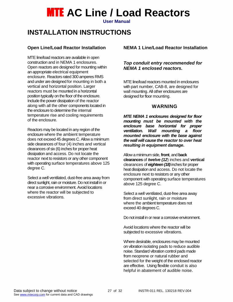
INSTALLATION INSTRUCTIONS
Open Line/Load Reactor Installation
MTE line/load reactors are available in openconstruction and in NEMA 1 enclosures.Open reactors are designed for mounting withinan appropriate electrical equipmentenclosure. Reactors rated 300 amperes RMSand under are designed for mounting in both avertical and horizontal position. Largerreactors must be mounted in a horizontalposition typically on the floor of the enclosure.Include the power dissipation of the reactoralong with all the other components located inthe enclosure to determine the internaltemperature rise and cooling requirementsof the enclosure.
Reactors may be located in any region of theenclosure where the ambient temperaturedoes not exceed 45 degrees C. Allow a minimumside clearances of four (4) inches and verticalclearances of six (6) inches for proper heatdissipation and access. Do not locate thereactor next to resistors or any other componentwith operating surface temperatures above 125degree C.
Select a well ventilated, dust-free area away fromdirect sunlight, rain or moisture. Do not install in ornear a corrosive environment. Avoid locationswhere the reactor will be subjected toexcessive vibrations.
NEMA 1 Line/Load Reactor Installation
Top conduit entry recommended forNEMA 1 enclosed reactors.
MTE line/load reactors mounted in enclosureswith part number, CAB-8, are designed forwall mounting. All other enclosures aredesigned for floor mounting.
WARNING
MTE NEMA 1 enclosures designed for floormounting must be mounted with theenclosure base horizontal for properventilation. Wall mounting a floormounted enclosure with the base againstthe wall will cause the reactor to over heatresulting in equipment damage.
Allow a minimum side, front, and backclearances of twelve (12) inches and verticalclearances of eighteen (18) inches for properheat dissipation and access. Do not locate theenclosure next to resistors or any othercomponent with operating surface temperaturesabove 125 degree C.
Select a well ventilated, dust-free area awayfrom direct sunlight, rain or moisturewhere the ambient temperature does notexceed 40 degrees C.
Do not install in or near a corrosive environment.
Avoid locations where the reactor will besubjected to excessive vibrations.
Where desirable, enclosures may be mountedon vibration isolating pads to reduce audiblenoise. Standard vibration control pads madefrom neoprene or natural rubber andselected for the weight of the enclosed reactorare effective. Using flexible conduit is alsohelpful in abatement of audible noise.
MTE AC Line / Load ReactorsUser Manual
Data subject to change without notice 28 of 32 INSTR-011 REL. 130218 REV.004See www.mtecorp.com for current data and CAD drawings
Power Wiring Connection
WARNINGInput and output power wiring to thereactor should be performed byauthorized personnel in accordancewith the NEC and all local electricalcodes and
REGULATIONS
Verify that the power source to which the reactoris to be connected is in agreement with thenameplate data on the reactor. A fuseddisconnect switch or circuit breaker should beinstalled between the reactor and its source ofpower in accordance with the requirements ofthe NEC and all local electrical codes andregulations. Refer to the drive, inverter, or otherelectrical equipment user manual for selection ofthe correct fuse rating and class.
The reactor is suitable for use on a circuitcapable of delivering not more than 65,000 rmssymmetrical amperes at 480 volts whenprotected by Bussman type JJS, KTK, KTK-R,SPP or T class fuses.
Reactor are designed for use with copperconductors with a minimum temperature ratingof 75 degrees C. Table 2 lists the wire range andterminal torque requirements for the power inputand output connections by reactor part number.
Refer to Figure 4 for typical electrical diagramsdescribing the application of reactors in both lineand load applications. For reactors supplied as acomponent part of a drive system or acomponent part of power electronic apparatusfollow the interconnection diagram supplied bythe System Engineer.
Where desirable, a flexible conduit connection tothe reactor enclosure should be made to reduceaudible noise.
WARNING
Failure to connect reactors suppliedas a component part of a drivesystem or other power electronicsystem according to the systeminterconnection diagram supplied bythe System Engineer will result inequipment damage, injury, or death.
WARNING
If a line reactor or a line reactor and a loadreactor are used with a drive equipped with abypass circuit, the reactors must be removedfrom the motor circuit in the bypass mode.Damage to the motor and other equipment willresult if this warning is not observed.
GroundingA stud is provided on enclosed reactors forgrounding the enclosure. The enclosure must begrounded. Open reactors must be grounded atthe designated grounding terminal or the reactormounting holes if no designated groundingterminal is provided.
WARNING
The frame of line/load reactors must begrounded at the designated grounding terminal
or one of the reactor mounting holes if nodesignated grounding terminal is provided. The
enclosure of reactors supplied in enclosuresmust be grounded.
INJURY OR DEATH MAY RESULT IFSAFETY PRECAUTIONS ARE NOT
OBSERVED.
MTE AC Line / Load ReactorsUser Manual
Data subject to change without notice 29 of 32 INSTR-011 REL. 130218 REV.004See www.mtecorp.com for current data and CAD drawings
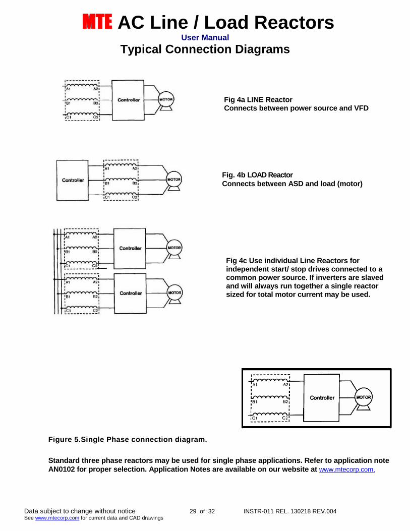
Typical Connection Diagrams
Figure 5.Single Phase connection diagram.
Standard three phase reactors may be used for single phase applications. Refer to application noteAN0102 for proper selection. Application Notes are available on our website at www.mtecorp.com.
Fig 4a LINE ReactorConnects between power source and VFD
Fig. 4b LOAD ReactorConnects between ASD and load (motor)
Fig 4c Use individual Line Reactors forindependent start/ stop drives connected to acommon power source. If inverters are slavedand will always run together a single reactorsized for total motor current may be used.
MTE AC Line / Load ReactorsUser Manual
Data subject to change without notice 30 of 32 INSTR-011 REL. 130218 REV.004See www.mtecorp.com for current data and CAD drawings
Sequence of Operation
1. Read and follow safety precautions.
2. After installation, ensure that: All Reactor ground terminals are connected to ground. Power wiring to the utility, drive and motor is in accordance with the
interconnection diagrams supplied by the System Engineer.
3. Check that moisture has not condensed on the Reactor. If moisture ispresent, do not proceed with startup until the moisture has been removed.
4. Proceed with startup according to the instructions provided by the systemsupplier.
WARNING
Reactors are a component part of an electrical system. Do not proceed with startup untilthe system startup instructions provided by the System Engineer are understood andfollowed. Injury, death and damage to equipment may result if the system startupinstructions are not followed.
WARNING
Use extreme caution to avoid contact with line voltage when checking forpower.
INJURY OR DEATH MAY RESULT IF SAFETY PRECAUTIONS ARENOT OBSERVED.
MTE AC Line / Load ReactorsUser Manual
Data subject to change without notice 31 of 32 INSTR-011 REL. 130218 REV.004See www.mtecorp.com for current data and CAD drawings
STARTUP
Safety Precautions
Before startup, observe the following warnings and instructions:
WARNING
A Reactor is at line potential when the Reactor is connected to the utility. This voltageis extremely dangerous and may cause death or severe injury if you come in contact
with it.
WARNING
High voltage is used in the operation of line/load reactors. Use Extreme caution toavoid contact with high voltage when operating, installing or repairing equipmentcontaining line/load reactors. Line/load reactors are used in conjunction withinverters, or other electrical equipment that may feedback lethal voltages.
Follow the safety instructions in the equipment used with the reactor in additionto the safety instruction in this manual.
INJURY OR DEATH MAY RESULT IF SAFETYPRECAUTIONS ARE NOTOBSERVED.