Embed Size (px)
Citation preview

McIntosh Laboratory, Inc. 2 Chambers Street Binghamton, New York 13903-2699 Phone: 607-723-3512 www.mcintoshlabs.com
MT2
Precision Turntable
Owner’s Manual

2
Safety Instructions ......................................................2 (Separate Sheet) ............................Important Additional Operation Information GuideThank You and Please Take a Moment .......................2Technical Assistance and Customer Service ..............2Table of Contents ........................................................2General Information ...................................................3Connector and Cable Information ..............................3Introduction .................................................................4Performance Features .................................................4Dimensions .................................................................5Unpacking the Turntable .............................................6Assembling the Turntable ........................................7-9Installing a non-supplied Cartridgeand Tone Arm Adjustments .................................10-12Trackability Adjustments ..........................................12Rear Panel Connections and Adjustments ................13How to Connect the Turntable .................................. 14Switches, Lever and Record Clamp .......................... 15How to Operate the Turntable ................................... 16Photo ......................................................................... 17Specifications ............................................................ 18Packing Instruction ................................................... 19
Your decision to own this McIntosh MT2 Turntable ranks you at the very top among discriminating music listeners. You now have “The Best.” The McIntosh dedication to “Quality,” is assurance that you will re-ceive many years of musical enjoyment from this unit.Please take a short time to read the information in this manual. We want you to be as familiar as pos-sible with all the features and functions of your new McIntosh.
Copyright 2017 © by McIntosh Laboratory, Inc.
Table of ContentsThank You
Please Take A Moment
Technical AssistanceIf at any time you have questions about your McIntosh product, contact your McIntosh Dealer who is familiar with your McIntosh equipment and any other brands that may be part of your system. If you or your Dealer wish additional help concerning a suspected problem, you can receive technical assistance for all McIntosh products at:
McIntosh Laboratory, Inc.2 Chambers StreetBinghamton, New York 13903Phone: 607-723-3512Fax: 607-724-0549
Customer ServiceIf it is determined that your McIntosh product is in need of repair, you can return it to your Dealer. You can also return it to the McIntosh Laboratory Service Department. For assistance on factory repair return procedure, contact the McIntosh Service Department at:McIntosh Laboratory, Inc.2 Chambers StreetBinghamton, New York 13903Phone: 607-723-3515Fax: 607-723-1917
The serial number, purchase date and McIntosh Dealer name are important to you for possible insurance claim or future service. The spaces below have been provided for you to record that information:Serial Number: _______________________________
Purchase Date: _______________________________
Dealer Name: ________________________________
Important Safety Information is supplied in a separate document “Important Additional Operation Information Guide”

3
General InformationCaution: To prevent possible damage to the turntable
platter bearing, do not transport the MT2 Preci-sion Turntable with the platter installed.
1. For additional connection information, refer to the owner’s manual(s) for any component(s) connected to the MT2 Precision Turntable.
2. The MT2 Precision Turntable comes with the Sumiko BP2 High Output Moving Coil Cartridge.
3. It is recommended the Professionals at your Mc-Intosh Dealer, who are skilled in all aspects of Turntables and Phono Cartridges, install the MT2 Precision Turntable and any associated audio equip-ment.
4. For optimum performance, the setup and adjust-ment of the MT2 Precision Turntable requires special test recordings and test/measurement equip-ment. Contact your McIntosh Dealer for additional information and assistance.
5. The MT2 Precision Turntable is supplied with the Sumiko Blue Point 2 High Output Moving Coil Cartridge. The Sumiko Blue Point 2 output level is compatible with the MM (Moving Magnet) Input on most McIntosh Preamplifiers, Integrated Am-plifiers and A/V Control Center. It is designed to playback 33-1/3 rpm and 45 rpm vinyl recordings. Contact your McIntosh Dealer for additional infor-mation and assistance.
6. When discarding the unit, comply with local rules or regulations. Batteries should never be thrown away or incinerated but disposed of in accordance with the local regulations concerning battery disposal.
7. For additional information on the MT2 and other McIntosh Products please visit the McIntosh Web Site at www.mcintoshlabs.com.
Tonearm Headshell WiringRefer to the following list of wire colors in the head-shell for installing the cartridge into the Headshell: Cartridge Connections Headshell Wire Color Left Channel (+) White Left Channel (-) Blue Right Channel (+) Red Right Channel (-) Green
Sumiko BP2 Cartridge ConnectionsRefer to the following illustration when connecting the McIntosh Cartridge in the Headshell:
Phono Cartridge Connection Information
RL
EL ER
Right Channel (-)
Right Channel (+)
Left Channel (-)
Left Channel (+)
Rear View of Sumiko BP2 Cartridge
General Information and Cable Information
8. When an AC Line Cord is used to connect the supplied AC / DC Adapter to an AC Outlet, it is im-portant the line cord conductor size is a minimum 0.75mm2 for each leg of the two conductor cord.
9. If it should become necessary to replace the sup-plied AC / DC Adapter and/or the plug adapters, order part number 320508SP from the McIntosh Parts Department. Refer to the illustration below.

4
Introduction
Performance Features
The McIntosh MT2 Precision Turntable with the Sumiko BP2 High Output Moving Coil Cartridge of-fers the latest in playback of vinyl recordings. A full complement of performance features allows for the enjoyment of all recordings reproduced with flaw-less realism. The advanced electronic and mechanical design ensures many years of smooth trouble free operation.
• Advanced Technology TurntableThe MT2 combines the latest technology in Phono Cartridges, Tone Arms, Mechanical Suspensions and Record Platter Rotation for superb performance and accurate operation.
• Moving Coil CartridgeThe Sumiko BP2 High Output Moving Coil Car-tridge has the inherent correctness of the impeccable mechanical and electrical design. High impedance, together with high output voltage, ensures noise free musical reproduction. This unique high output design features an alloy cantilever, elliptical diamond stylus with exceptional tracking capability. The ruler-flat frequency response from 20Hz to 20kHz provides solid realistic bass, uncolored midrange and natural high frequencies.
• Tone ArmThe MT2 tonearm is made from dural aluminium with special damping material. The tonearm is both light in weight and highly rigid. The noise free vertical bearings are made from two high precision ceramic surfaces with damping fluid. The horizontal bearing is a gimballed sapphire design.
Introduction and Performance Features
• Turntable PlattersThe full size outer platter is made from a special dy-namically balanced polyoxymethylene (POM), weighs 5.07 pounds, 1.18 inches thick. This helps to resist and absorb external vibrations from reaching the record during playback and its large mass provides the perfect flywheel action for stable playback speed. The inner platter is made of CNC-precision milled aluminium, weighs 0,96 pounds and is six and one quarter inches in diameter.
• Precision Motor and Drive ElectronicsThe DC motor is fed by an external voltage-stabilized power supply and is completely decoupled from the chassis, isolating the record from any mechanical interference.
• Two Playback Speeds with fine AdjustmentsThe MT2 Turntable has two playback speed, 33 rpm and 45 rpm. There is a separate trim adjustment al-lowing for accurate music reproduction for each of the two speeds.
• BearingThe MT2 Turntable Platter rotates on a Polished and Tempered Steel Shaft in a sintered bronze bushing and is coated with Teflon.
• Multi-Layered Dampened ChassisThe MT2 Turntable Chassis has a resonance opti-mized and highly compressed wood chassis with black lacquer. The top and middle plate which is made of acrylic also absorb vibrations.
• Fiber Optic Solid State IlluminationThe even illumination of the top panel and the turn-table platter is accomplished by the combination of custom designed fiber optic light diffusers and extra long life light emitting diodes (LEDs).
5
Dimensions
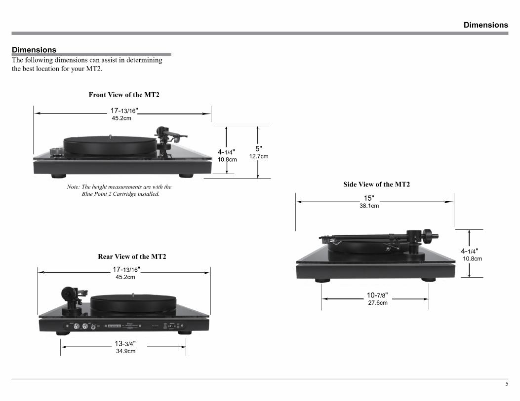
DimensionsThe following dimensions can assist in determining the best location for your MT2.
Side View of the MT2
15"38.1cm
4-1/4" 10.8cm
10-7/8" 27.6cm
Front View of the MT2
17-13/16" 45.2cm
4-1/4" 10.8cm
5" 12.7cm
Note: The height measurements are with the Blue Point 2 Cartridge installed.
Rear View of the MT2
17-13/16" 45.2cm
13-3/4" 34.9cm

6
Unpacking the Turntable
Unpacking the TurntableTo protect the fine finish of the MT2 Precision Turn-table during the assembly and adjustment process, it is advisable to prepare a suitable clean working area with a soft, clean fabric, such as a bed linen or blanket.
It is recommended that the Professionals at your McIntosh Dealer, who are skilled in all aspects of in-stallation and operation, unpack, assemble, adjust and install the MT2 Precision Turntable.
CAUTION: To prevent possible damage to the turn-table platter bearing, do not move the MT2 Precision Turntable after the Outer Platter is installed.
1. Referring to the illustration on the right, open the shipping carton and carefully remove the following items from the carton and place them in the previ-ously prepared working area:
A. Owner’s Manual Pack, Record Mat Tone Arm/Cartridge Alignment Gauge and Pair of Gloves B. Dust Cover C. Turntable D. Outer Platter E. Accessories: 1. Record Clamp 2. AC/DC Adapter and Plugs 3. Belt 4. Grounding Cable 5. Bearing Oil1 6. Bubble Level 7. Cartridge Mounting Screws 8. Tonearm Counter Weight 9. Screw Driver and Allen Wenches 10. Stylus Force Gauge2. Proceed to Assembly of the Turntable starting on
the next page.CAUTION: To prevent possible damage to the Cartridge
Stylus, DO NOT remove the Stylus Guard at this time.
Foam PackingMaterial
Owners Manual
Record Matand CartridgeAlignment Gauge
Dust Cover
Turntable
Accessory Location
Foam PackingMaterial
Shipping Carton
Pair of Gloves
Air BubblePacking Material
Outer Platter
1 Some time in the distant future, the inside vertical shaft located below the Inner Platter might require one or two drops of oil.

7
4. Next, take the Outer Platter and slowly lower it onto the Inner Platter making sure to keep the Outer Platter parallel to the Turntable surface as it is being lowered. Refer to figure 3.
Place the Turntable in the location where it will be used. Please keep in mind; the turntable should be the greatest possible distance from the system loudspeak-ers to reduce the chance of acoustic feedback. To minimize the possibility of the cartridge stylus jump-ing record grooves, place the turntable on a mechani-cally stable surface such as wall shelving anchored to wall studs. Perform the following assembly steps:
Note: It is recommended the installation and adjustment of the McIntosh MT2 Precision Turntable be performed by the Professionals at your McIntosh Dealer.
1. Remove the protective mesh from the Turntable Vertical Bearing Shaft. Refer to figure 1.
2. Using the supplied cloth gloves, place the belt onto the circumference of the inner platter and then onto the pulley of the motor. Rotate the in-ner platter by hand while seating the belt into it. Refer to figure 2.
Assembling the Turntable
Figure 2
Motor Pulley
Belt
Figure 1
RemoveProtective Mesh
5. Locate the Record Mat and place it on top of the platter. Refer to figure 4.
6. Locate the McIntosh Bubble Level and place it on the Record Mat. Refer to figure 5.If the Bubble is not in the center circle of the Bubble Level, adjust the height of the Turntable Feet (by rotat-ing them clock-wise or counter clockwise) until it is level. Refer to figures 6 and 7 on the next page.
Figure 3
Outer Platter
Figure 4
Record Mat
Assembling the Turntable
BubbleLevel
Figure 5

8
7. Locate the Tone Arm Counterweight and the supplied small bottle of Bearing Oil. Using a small cotton swap (Q-Tip) apply one drop of the oil to the inside center of the Counterweight “O” Rings. Refer to figure 8.
9. Remove the protective film material from the Tone Arm Rest Position. Refer to figures 12 and 13.
Note: If another Phono Cartridge (such as the McIntosh MCC10) is to be used with the MT2 turntable, proceed to “Installing a non-supplied Cartridge” at this time on page 10.
8. Align the inside opening of the Counterweight with the rear end of the Tone Arm. Then slowly rotate the Counterweight until the front vertical surface of it lines up with the center of the Blue Point. The center of Blue Point Position Marking on the surface of the Tone Arm is for the supplied No. 2 Cartridge. Refer to figures 9, 10 and 11.
Note: It is recommended to check the tracking force pressure using the supplied Sty-lus Tracking Force Gauge as outlined on page 12.
Figure 9
Blue Point No. 2Position Marking
Center of the Blue Point No. 2 Position
Assembling the Turntable, con’t
Figure 6Bottom Foot
Figure 7Turn to adjust height
Figure 10
Figure 11
Center of PositionMarking
Figure 12
ProtectiveFilm
Figure 8
Coat the inside “O” Rings with a drop of Oil
9
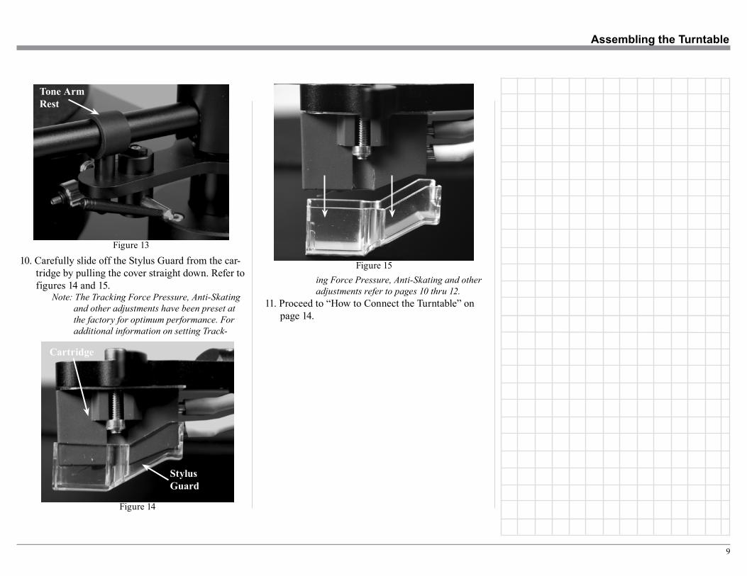
10. Carefully slide off the Stylus Guard from the car-tridge by pulling the cover straight down. Refer to figures 14 and 15.
Note: The Tracking Force Pressure, Anti-Skating and other adjustments have been preset at the factory for optimum performance. For additional information on setting Track-
Figure 14
StylusGuard
Cartridge
Figure 13
Tone ArmRest
Assembling the Turntable
ing Force Pressure, Anti-Skating and other adjustments refer to pages 10 thru 12.
11. Proceed to “How to Connect the Turntable” on page 14.
Figure 15
10
CAUTION: To prevent possible damage to the turn-table platter bearing, do not move the MT2 Precision Turntable with the platters installed.
In the event a non-supplied Phono Cartridge is to be installed into the McIntosh MT2 Turntable, please fol-low the steps below:
Note: It is recommended that the Professionals at your McIntosh Dealer, who are skilled in all aspects of installation and adjustment of the McIntosh MT2 Precision Turntable, perform the assembly, installation and adjustments.
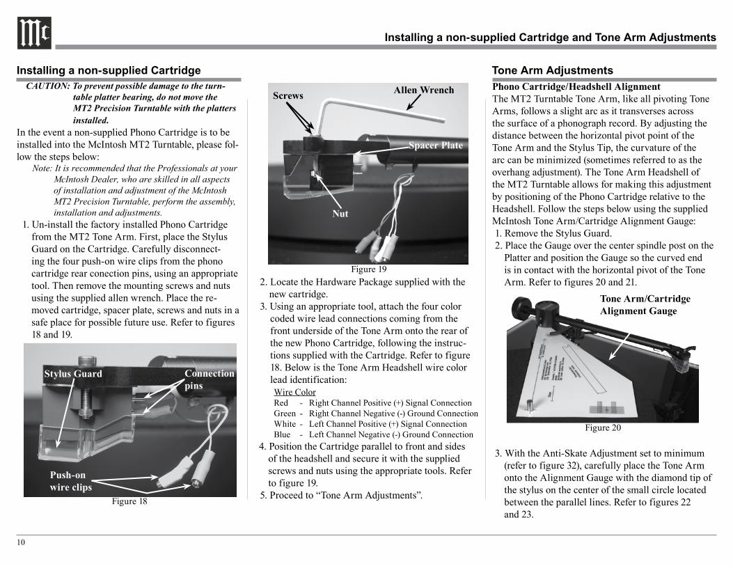
1. Un-install the factory installed Phono Cartridge from the MT2 Tone Arm. First, place the Stylus Guard on the Cartridge. Carefully disconnect-ing the four push-on wire clips from the phono cartridge rear conection pins, using an appropriate tool. Then remove the mounting screws and nuts using the supplied allen wrench. Place the re-moved cartridge, spacer plate, screws and nuts in a safe place for possible future use. Refer to figures 18 and 19.
2. Locate the Hardware Package supplied with the new cartridge.
3. Using an appropriate tool, attach the four color coded wire lead connections coming from the front underside of the Tone Arm onto the rear of the new Phono Cartridge, following the instruc-tions supplied with the Cartridge. Refer to figure 18. Below is the Tone Arm Headshell wire color lead identification:
Wire Color Red - Right Channel Positive (+) Signal Connection Green - Right Channel Negative (-) Ground Connection White - Left Channel Positive (+) Signal Connection Blue - Left Channel Negative (-) Ground Connection4. Position the Cartridge parallel to front and sides
of the headshell and secure it with the supplied screws and nuts using the appropriate tools. Refer to figure 19.
5. Proceed to “Tone Arm Adjustments”.
Installing a non-supplied Cartridge Tone Arm AdjustmentsPhono Cartridge/Headshell AlignmentThe MT2 Turntable Tone Arm, like all pivoting Tone Arms, follows a slight arc as it transverses across the surface of a phonograph record. By adjusting the distance between the horizontal pivot point of the Tone Arm and the Stylus Tip, the curvature of the arc can be minimized (sometimes referred to as the overhang adjustment). The Tone Arm Headshell of the MT2 Turntable allows for making this adjustment by positioning of the Phono Cartridge relative to the Headshell. Follow the steps below using the supplied McIntosh Tone Arm/Cartridge Alignment Gauge:1. Remove the Stylus Guard.2. Place the Gauge over the center spindle post on the
Platter and position the Gauge so the curved end is in contact with the horizontal pivot of the Tone Arm. Refer to figures 20 and 21.
3. With the Anti-Skate Adjustment set to minimum (refer to figure 32), carefully place the Tone Arm onto the Alignment Gauge with the diamond tip of the stylus on the center of the small circle located between the parallel lines. Refer to figures 22 and 23.
Installing a non-supplied Cartridge and Tone Arm Adjustments
Figure 18
Push-on wire clips
Connection pins
Stylus Guard
Figure 19
Spacer Plate
Nut
Screws Allen Wrench
Figure 20
Tone Arm/Cartridge Alignment Gauge

11
Note: It may be necessary to slide the Phono Car-tridge forward or backward in the headshell to position the stylus in the center of the circle.
4. It is important the Front and Sides of the Cartridge Body line up with these parallel lines when look-ing down over the top of the Tone Arm. Refer to figures 23 and 24. If it is not parallel, loosen the mounting hardware securing the Phono Cartridge to the Tone Arm. Reposition the Phono Cartridge so the tip of the stylus is in the center of the small circle and the Front and Sides of the Phono Car-tridge are parallel to the lines on the Alignment Gauge. Tighten up the mounting hardware and verify the correct alignment.
Tone Arm HeightTo assure the best sound reproduction, it is very important the MT2 Tone Arm is parallel to the record surface during playback. The height of the Tone Arm is adjustable to accommodate the different Phono Car-tridge physical heights. To adjust for the proper Tone Arm Height, perform the following the steps:1. Release the Tone Arm from the Tone Arm Rest,
place it on a record and check to see if the Tone
Arm is parallel to the surface of the record. Refer to figure 25. With the Tone Arm parallel, no adjustment is needed and proceed to “Set-ting the Tracking Force Pressure”. If the Tone Arm is not parallel, note whether the rear of the Tone Arm needs to go up or down.
2. With the Tone Arm secured in the Tone Arm Rest, carefully loosen the set screw while supporting the rear of the Tone Arm. Reposition the Tone Arm based on findings in the previous step. Temporarily tighten one of the set screws. Refer to figure 26.
3. Release the Tone Arm from the rest and place it on a record and check to see if the Tone Arm is now parallel. Also check to make sure the Tone Arm is parallel to the record platter and the right side of the turntable base. Refer to figure 27.
Figure 22
Location of circle
Figure 21Horizontal pivot
Tone Arm/Cartridge Alignment Gauge
Figure 23
Stylus Tip in the center of the circle
Figure 24
Allen Wrench
Figure 26
Figure 25
Tone ArmHeight Set Screw
Figure 27
The Tone Arm Height is adjusted for the Arm to be parallel to the record surface

12
4. With the Tone Arm parallel to the record surface, record platter and turntable base, tighten the set screw, which was loosened in step 2. If not, repeat steps 1, 2 and 3 until the Tone Arm is parallel.
Setting the Tracking Force PressureThe MT2 is supplied with a Stylus Tracking Force Gauge for checking and adjusting the Stylus Track-ing Pressure. The Gauge uses the “Balance Scale” methodology for measurement. Place the Gauge on the record mat and perpendicular to the front of the Tone Arm, with the Stylus Tip over graduation marks. Set the Anti-Skate Adjustment to minimum (refer to
figure 32). Adjust the position of the Tone Arm Coun-terweight to establish a tracking force pressure in the middle of the recommend range from the Cartridge manufacturer as a starting place. Refer to figures 28 thru 31.
Note: Usually, adjusting the tracking force pressure closer to the maximum setting recommend by the Cartridge Manufacturer will produce better sound with less record and stylus wear. Refer to “Trackability Adjustments” for additional information.
Anti-Skating AdjustmentThe MT2 has adjustable Anti-Skating to equalize the pressure on both sides of the record groove wall by rotating the Anti-Skating Weight Up and Down the threaded shaft, refer to figure 32.
For additional information about Tracking Force Pres-sure and Anti-Skating refer to “Trackability Adjust-ments”.
Installing a non-supplied Cartridge and Tone Arm Adjustments
Trackability AdjustmentsDuring playback of Phonograph Recordings, the stylus assembly is subjected to all kinds of extreme operat-ing conditions. One of those conditions is the forces constantly trying to push the stylus up and out of the grooved wall of the recording. Another condition is the uneven side to side pressure applied to the stylus as it tries to stay in contact with both sides of the groove wall of the recording. Refer to figure 35.
The Anti-Skating Adjustment permits equalizing for even side to side pressure. The correct amount of Tracking Force Pressure and Anti-Skate Pressure var-ies with the exact shape of the Stylus Tip and finally the audio signal (both frequency and amplitude) con-tained in the groove wall of the record.
To achieve good performance and the least amount of Stylus Tip/Record Groove wear, use a Trackablity Test Record. Both Tracking Force and Anti-Skate Ad-justments are made as a result of listening to the test record to reduce different forms of audible distortions. Never exceed the manufacturers recommend Maxi-mum Tracking Force Pressure Setting.
Your McIntosh Dealer, using Test Measurement Equipment and Professional Test Recordings, can achieve via adjustments, the best possible sound qual-ity from your record collection and ensure the greatest longevity.
Figure 35
Figure 28
Stylus Force Gauge
Stylus Tip
Cartridge
Stylus Pressure Scale(Graduations are in grams)
Figure 29
Stylus Pressure Set higher than gauge marking
Figure 30
Stylus Pressure Set lower than gauge marking
Figure 31
Stylus Pressure Set the same as gauge marking
Figure 32
AntiskatingWeight
Antiskating Adjustment
Maximum
Minimum
13
Rear Panel Connections and Adjustments
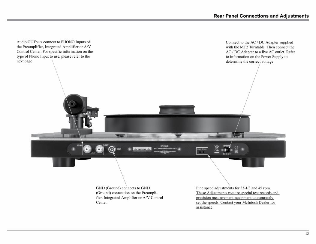
Connect to the AC / DC Adapter supplied with the MT2 Turntable. Then connect the AC / DC Adapter to a live AC outlet. Refer to information on the Power Supply to determine the correct voltage
Audio OUTputs connect to PHONO Inputs of the Preamplifier, Integrated Amplifier or A/V Control Center. For specific information on the type of Phono Input to use, please refer to the next page
Fine speed adjustments for 33-1/3 and 45 rpm. These Adjustments require special test records and precision measurement equipment to accurately set the speeds. Contact your McIntosh Dealer for assistance
GND (Ground) connects to GND (Ground) connection on the Preampli-fier, Integrated Amplifier or A/V Control Center

14
How to Connect the Turntable
How to Connect the Turntable1. Connect a wire from the MT2 GND (Ground)
Post to the GND (Ground) Post on the McIntosh Preamplifier, Integrated Amplifier or A/V Control Center.
2. Connect Audio Cables from the MT2 OUT LEFT and RIGHT Jacks to the MC (Moving Coil) Inputs on a McIntosh Preamplifier, Integrated Amplifier or A/V Control Center.
Notes: 1. The MT2 Turntable with the Blue Point No. 2 High Output Moving Coil Car-tridge may also be connected to most McIntosh Preamplifiers, Integrated Amplifiers or A/V Control Centers with a Moving Magnet Phono Input.
2. For additional information about ob-taining optimum performance from the installed phono cartridge, refer to page 16 “Phono Cartridge Loading”.
3. Contact your McIntosh Dealer for ad-ditional information and assistance.
3. Connect the supplied AC / DC Adapter to the MT2 DC IN 12V socket and the Power Supply to a live AC outlet.
Preamplifier
MT2 AC/ DC Adapter

15
Switch, Lever and Record Clamp
Power and Speed Switch turns AC Power OFF or On with selection of 33 1/3 rpm or 45 rpm Playback speed
Record clamp helps to keep the phono-graph recording flat during playback
Raises and lowers the Tuntable Tone Arm

16
Tone Arm LiftThe McIntosh MT2 Precision Turntable has a Tone Arm Lift Mechanism for safe placement and removal of the cartridge stylus on the phonograph record. Per-form the following steps:1. Push on the top part of the Tone Arm Lift Lever
towards the rear of the turntable. Refer to figure 37.
2. Release the Tone Arm from the Tone Arm Holder.3. Position the Tone Arm over the desired spot of the
Phonograph record.4. Pull on the top part of the Tone Arm Lift Lever to-
wards the front of the turntable to begin playback.
Power and Speed SelectionRotate the POWER and SPEED Switch to select the playback speed (33-1/3 rpm or 45 rpm) of the phonograph record to be played. Refer to figure 36.
Power Off - The Top Panel illu-mination is switched OFF and there is no Turntable Platter rotation.
Power 33 - The Top Panel is illumination and the Turntable Platter is rotating at the 33-1/3 rpm speed.
Power 45 - The Top Panel is illumination and the Turntable Platter is rotating at the 45 rpm speed.
Phono Cartridge LoadingFor optimum performance it is important the Phono-Cartridge be connected to the correct load impedance. Refer to the respective Owner’s Manual for the Pream-plifier, Integrated Amplifier or Audio/Video Control Center used with the MT2 for additional information.
The Blue Point #2 Cartridge supplied with the MT2 Turntable is a Moving Coil Type with High Output. Set the load resistance to 1,000 Ohms (or the closest available value).
How to Operate the Turntable
How to Operate the Turntable
Figure 36
Figure 37
Tone Arm Holder
Tone Arm Lift Lever

17
Photo

18
General SpecificationsMT2 Turntable SpecificationsPlayback Speeds33 1/3 rpm and 45 rpm
Motor TypeDC Stainless Steel Brushes
Speed ControlServo System
Blue Point No.2 Cartridge SpecificationsCartridge TypeMoving Coil, High Output
Output Level2.5 mV at 5 cm/s
Load Impedance1000 ohms recommended (Preamp MC Input)
Frequency Response20Hz to 50,000Hz
Channel Separation35dB at 1kHz
Channel BalanceLess than 0.5 dB at 1kHz
Tracking Force Range1.6 to 2.0 grams
Recommended Tracking Force2.0 grams
Compliance15 x 10-6 cm/dyne
Total Mass6.3 grams
StylusElliptical Diamond
Cantilever MaterialAluminum
Specifications
Overall DimensionsWidth is 17-13/16 inches (45.2cm)Height is 5 inches (12.7cm) (without Dust Cover)
Note: The Turntable Height is affected by the type of Cartridge installed and the required Tone Arm Height Adjustment.
Height is 6 inches (15.2cm) (with Dust Cover)Depth is 17 inches (43.2cm) (including Cables)
Weight29 pounds (13.2Kg) net, 39 pounds (17.6Kg) in ship-ping carton
Shipping Carton DimensionsWidth is 22-1/4 inches (56.5cm)Depth is 18 inches (45.7cm)Height is 15-1/2 inches (39.4cm)

19
Packing Instructions
Packing Instructions
In the event it is necessary to repack the equipment for shipment, the equipment must be packed exactly as shown below. It is very important the four feet are still attached to the bottom of the equipment. This will en-sure the proper equipment location on the Platter foam pads. Failure to do this will result in shipping damage.
Use the original shipping carton and interior parts only if they are all in good serviceable condition. If a shipping carton or any of the interior part(s) are need-ed, please call or write Customer Service Department of McIntosh Laboratory. Refer to page 2. Please refer to the Part List below for the correct part numbers.
Quantity Part Number Description 1 310599SP Top Foam Packing 1 310598SP Foam Packing for Top of the Dust Cover 1 310596SP Foam Packing for Bottom of the Dust Cover 1 310597SP Foam Packing for Top of the Turntable 1 310595SP Foam Packing for Accessories and Outer Platter Set 1 310594SP Shipping carton only
Top FoamPacking
Record Matand CartridgeAlignment Gauge
Dust Cover
Turntable
Foam Packingfor Top of theTurntable
Shipping Carton
Air BubblePacking
Outer Platter
Foam Packingfor Top of theDust Cover
Foam Packingfor Bottom of theDust Cover
Foam Packingfor Accessoriesand Outer Platter Set

The continuous improvement of its products is the policy of McIntosh Laboratory Incorporated who reserve the right to improve design without notice.Printed in the U.S.A.
McIntosh Laboratory, Inc.2 Chambers Street
Binghamton, NY 13903www.mcintoshlabs.com
McIntosh Part No. 04176101