Embed Size (px)
Citation preview
MT103MT103MT103MT103----102102102102////1111----In, 3In, 3In, 3In, 3----Out VGAOut VGAOut VGAOut VGA----Type DType DType DType DAAAA Card Card Card Card User’s Guide
400-0107-006
1
Welcome!
We greatly appreciate your purchase of the MT103-102 1-In, 3-Out
VGA-Type Distribution Amplifier Card. We are sure you will find it reliable
and simple to use. Superior performance for the right price, backed by solid
technical and customer support is what ALTINEX has to offer.
We are committed to providing our customers with
Signal Management Solutions® to the most demanding audiovisual
installations at very competitive pricing and we welcome you to join the
ranks of our many satisfied customers throughout the world.
1. Precautions and Safety Warnings
Please read this manual carefully before using your MT103-102 and keep it
handy for future reference. These safety instructions are to ensure the long
life of your MT103-102 and to prevent fire and shock hazards. Please read
them carefully and heed all warnings.
1.1 General
• Qualified ALTINEX service personnel or its authorized representatives
must perform all service.
1.2 Installation Precautions
• Handle the MT103-102 carefully. Dropping or jarring can damage the
card.
• The MT103-102 contains components that are sensitive to electrostatic
discharge (ESD). Always use ESD safety precautions when touching the
card.
• To prevent fire or shock, do not expose this unit to water or moisture.
Do not place the MT103-102 in direct sunlight, near heaters, or
heat-radiating appliances, or near any liquid. Exposure to direct
sunlight, smoke, or steam can harm internal components.
• Do not pull any cables that are attached to the MT103-102.
1.3 Cleaning
• Clean only the connector area with a dry cloth. Never use strong
detergents or solvents such as alcohol or thinner. Do not use a wet cloth
or water to clean the card. Do not clean or touch any component or
PCB.
1.4 FCC Notice
• This device complies with Part 15 of the FCC Rules. Operation is
subject to the following two conditions: (1) This device may not cause
harmful interference, and (2) this device must accept any interference
received, including interference that may cause undesired operation.
• This equipment has been tested and found to comply with the limits for
a Class A digital device, pursuant to Part 15 of the FCC Rules. These
limits are designed to provide reasonable protection against harmful
interference when the equipment is operated in a commercial
environment. This equipment generates, uses, and can radiate radio
frequency energy and, if not installed and used in accordance with the
instructions found herein, may cause harmful interference to radio
communications. Operation of this equipment in a residential area is
likely to cause harmful interference in which case the user will be
required to correct the interference at his own expense.
• Any changes or modifications to the unit not expressly approved by
ALTINEX, Inc. could void the user’s authority to operate the
equipment.
2. Installation Procedures
Step 1. Turn off power to the MultiTasker® system and disconnect from AC power.
Step 2. Remove a slot cover (MT200-101) from one of the unused slots. Identify the slot number and note that it is for RS-232 control.
Step 3. Slide the MT103-102 into the MultiTasker enclosure in order to connect to the bus. Make sure that the card fits into place and then secure the card by
tightening the retainer screws located on the top and bottom of the card.
Step 4. Restore power to the MultiTasker system.
Step 5. The LED on the card panel will turn red indicating that the card is in full operation. A green LED indicates that an input signal is present.
Step 6. Connect a VGA cable from the video source to the input connector of the MT103-102. Connect the output connectors of the MT103-102 to the
display devices through VGA cables.
Step 7. The MT103-102 is now operational.
3. Limited Warranty/Return policies
Please see the ALTINEX website at www.altinex.comfor details on warranty and return policies.
MTMTMTMT103103103103----102102102102 User’s Guide
400-0107-006
2
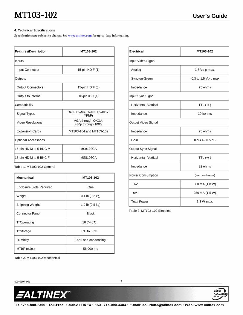
4. Technical Specifications
Specifications are subject to change. See www.altinex.com for up-to-date information.
Features/Description MT103-102
Inputs
Input Connector 15-pin HD F (1)
Outputs
Output Connectors 15-pin HD F (3)
Output to Internal 10-pin IDC (1)
Compatibility
Signal Types RGB, RGsB, RGBS, RGBHV, YPbPr
Video Resolutions VGA through QXGA, 480p through 1080i
Expansion Cards MT103-104 and MT103-109
Optional Accessories
15-pin HD M to 5-BNC M MS8102CA
15-pin HD M to 5-BNC F MS8106CA
Table 1. MT103-102 General
Mechanical MT103-102
Enclosure Slots Required One
Weight 0.4 lb (0.2 kg)
Shipping Weight 1.0 lb (0.5 kg)
Connector Panel Black
T° Operating 10°C-40°C
T° Storage 0°C to 50°C
Humidity 90% non-condensing
MTBF (calc.) 58,000 hrs
Table 2. MT103-102 Mechanical
Electrical MT103-102
Input Video Signal
Analog 1.5 Vp-p max.
Sync-on-Green -0.3 to 1.5 Vp-p max
Impedance 75 ohms
Input Sync Signal
Horizontal, Vertical TTL (+/-)
Impedance 10 kohms
Output Video Signal
Impedance 75 ohms
Gain 0 dB +/- 0.5 dB
Output Sync Signal
Horizontal, Vertical TTL (+/-)
Impedance 22 ohms
Power Consumption (from enclosure)
+6V 300 mA (1.8 W)
-6V 250 mA (1.5 W)
Total Power 3.3 W max.
Table 3. MT103-102 Electrical
MTMTMTMT103103103103----102102102102 User’s Guide
400-0107-006
3
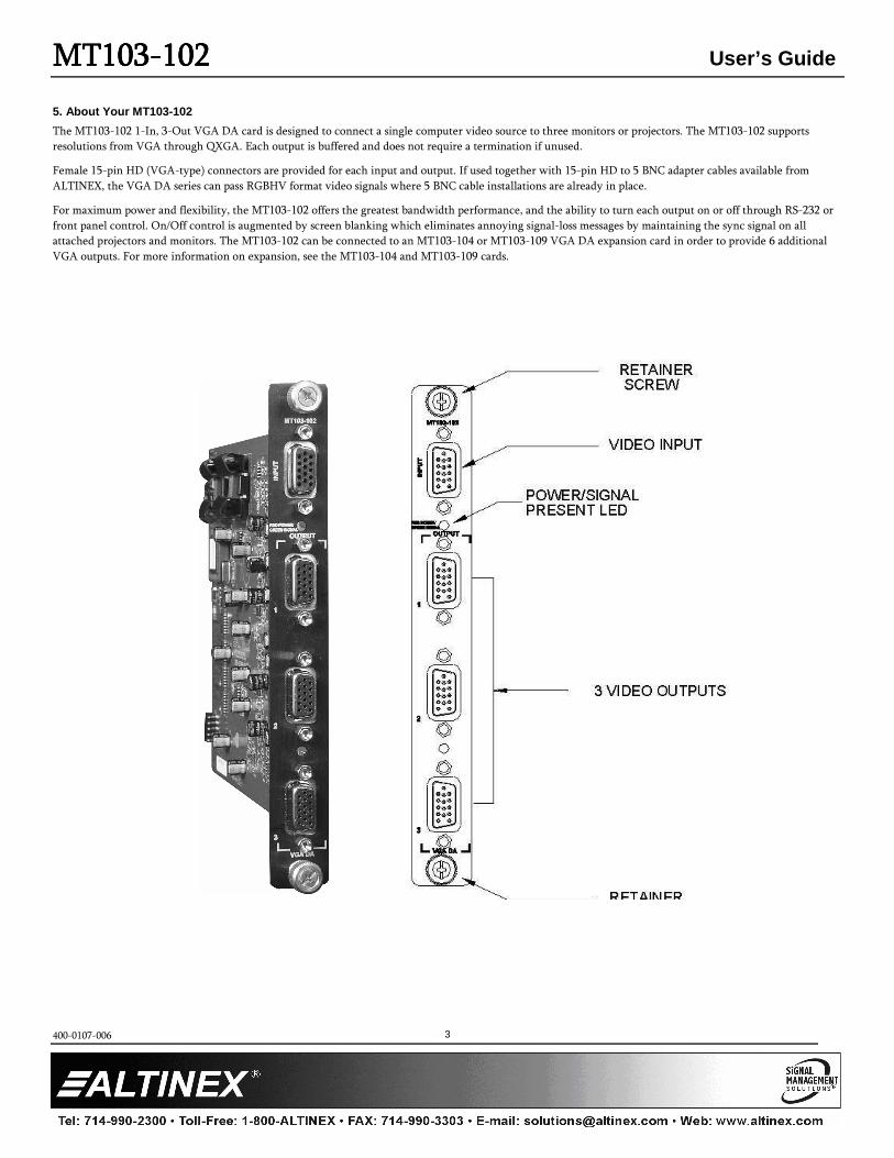
5. About Your MT103-102
The MT103-102 1-In, 3-Out VGA DA card is designed to connect a single computer video source to three monitors or projectors. The MT103-102 supports
resolutions from VGA through QXGA. Each output is buffered and does not require a termination if unused.
Female 15-pin HD (VGA-type) connectors are provided for each input and output. If used together with 15-pin HD to 5 BNC adapter cables available from
ALTINEX, the VGA DA series can pass RGBHV format video signals where 5 BNC cable installations are already in place.
For maximum power and flexibility, the MT103-102 offers the greatest bandwidth performance, and the ability to turn each output on or off through RS-232 or
front panel control. On/Off control is augmented by screen blanking which eliminates annoying signal-loss messages by maintaining the sync signal on all
attached projectors and monitors. The MT103-102 can be connected to an MT103-104 or MT103-109 VGA DA expansion card in order to provide 6 additional
VGA outputs. For more information on expansion, see the MT103-104 and MT103-109 cards.
MTMTMTMT103103103103----102102102102 User’s Guide
400-0107-006
4
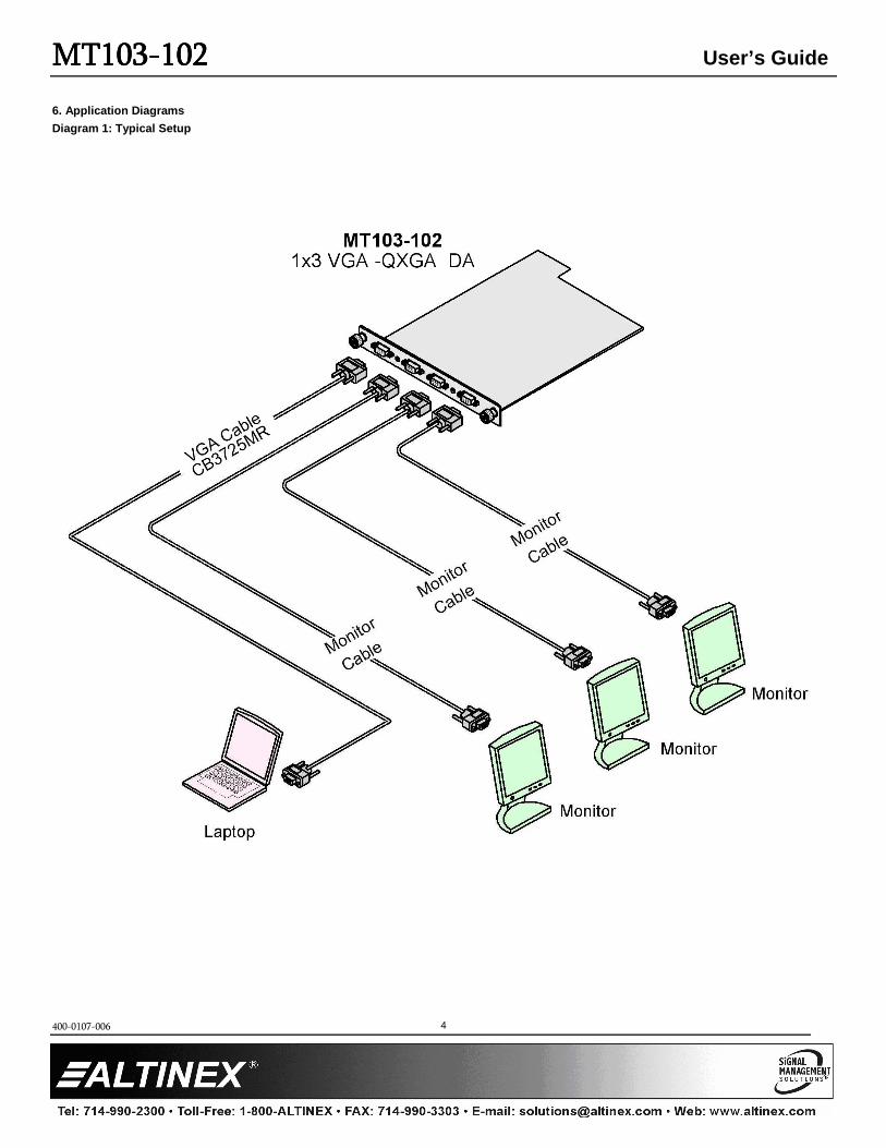
6. Application Diagrams
Diagram 1: Typical Setup
MTMTMTMT103103103103----102102102102 User’s Guide
400-0107-006
5
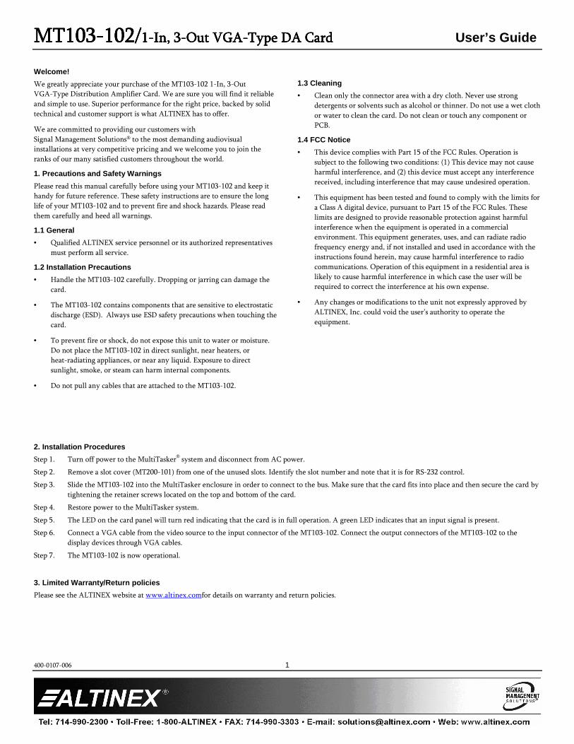
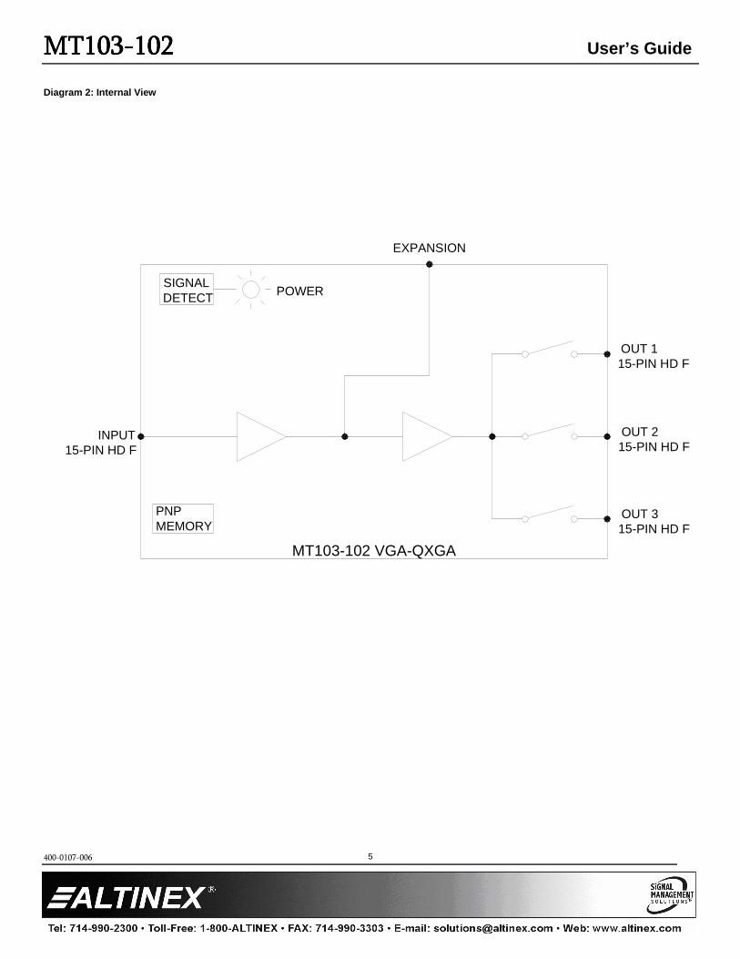
Diagram 2: Internal View
SIGNAL DETECT POWER
PNPMEMORY
INPUT
OUT 3
OUT 2
OUT 1
EXPANSION
15-PIN HD F
15-PIN HD F
15-PIN HD F
15-PIN HD F
MT103-102 VGA-QXGA
MTMTMTMT103103103103----102102102102 User’s Guide
400-0107-006
6
7. Operation
7.1 RS-232 Control
The MT103-102 has many advanced remote-control capabilities accessible
through standard RS-232 communication using a computer, control
system, or any device capable of RS-232 communication.
7.1.1 RS-232 Interface
The control commands for the MT106-103 are in a simple ASCII
character format.
1. Square brackets "[ ]" are part of the command.
2. Use uppercase letters for all commands.
3. Spaces are NOT legal characters.
The cards in a MultiTasker are capable of performing various
functions, as well as providing feedback to the user or control system.
Commands instruct a card to perform specific actions or request
information from the card. Some commands do both simultaneously.
A command that instructs the card only to perform an action will
generate feedback of "[ ]". The open bracket immediately followed by
a closed bracket indicates the card received a valid command. If the
command requested information from the card, the feedback
generated by the card is the acknowledgement of having received a
valid command. Invalid commands generate feedback that includes
"ERR" plus an error code.
Example 1: [ERR001] Error number
Example 2: [ERRC04] Card error C4
Commands ending in "S" will be saved into memory. Commands not
ending in "S" are executed, but not restored at reset or powered-up.
7.1.2 Conventions Used in this Manual
Card IDs:
In this manual, cards are referenced by their card ID; typically
equivalent to the slot number:
C1, C2, C3, C4 ... C99
Group IDs:
Groups are referenced by their group ID:
G1, G2, G3 ... G8
Unit IDs:
Units are referenced by their unit ID:
U0, U1, U2 ... U20
Examples for each command in the following sections do not
include the unit ID. Commands sent to a MultiTasker without a
unit ID are executed by all MultiTaskers connected to the
RS-232 bus. It is only necessary to include the unit ID when
there is more than one MultiTasker connected to the bus and
the command is intended for cards in that MultiTasker only.
[VERC3]: Executed by all MultiTaskers on the RS-232 bus.
[VERC3U1]: Executed by MultiTasker unit ID U1 only.
7.2 Description of Commands
Each command consists of three parts: Function, Card ID, and Unit ID.
[[[[ Function , Card ID , Unit ID ]]]]
Example: [VERC3U2]
VER = Function
C3 = Card ID or Group ID
U2 = Unit ID (optional for Unit ID 0)
For Function, see a detailed explanation under each description.
The card ID is a unique identifier. It is equal to the enclosure slot
number, or it may be an assigned value. As the slot number, the value
can range from 1-4 up to 1-20 depending on the enclosure. If the value
is assigned, the ID may be a maximum of 99. Card ID 0 (C0) is used for
the controller and cannot be reassigned.
The group ID is a number representing a group of cards defined with
the [WR] command. When using the group ID, all cards in the group
perform the given instruction.
Changing the position of a card significantly affects the commands
recorded on software definitions or third-party control systems.
Example:
[VERC3]: For U0 or all MultiTaskers on the bus.
[VERC3Ui]: For IDs other than U0 or all MultiTaskers.
[VERC3]: Equivalent to [VERC3U0] for U0.
Command Organization
The RS-232 commands in this section are organized into the following 5
categories:
Basic Commands
Feedback Control
Card Control
Card IDs
Groups
See the Summary of Commands (Section 7.3) for one-line descriptions of
each command.
MTMTMTMT103103103103----102102102102 User’s Guide
400-0107-006
7
Basic Commands
The basic commands are used to provide general information about the
card. These commands are most useful during the initial stages of setting
up and operating the card.
1. [VER]
This command displays the software version and model number for a
card.
Command Format: [VERCn]
Cn = Card ID (n = slot # from 1 to max slots)
Example:
An MT103-102 card is in slot 4. Send [VERC4], and receive feedback
similar to the following:
[MT103-102 690-0125-013 C04]
MT103-102 = the card model
690-0125-013 = the software version
2. [C]
This command displays the status of the card.
Command Format: [Cn]
Cn = Card ID (n = # from 1 to max slots)
Example:
Send [C4] to receive the card status:
ON: 1,2,3 C04
ON: 1,2,3 = Outputs 1-3 are enabled
C4 = Card ID is C4
If there is no card in slot 4, sending [C4] will not return any feedback.
3. [CnS]
This command saves the output on/off settings. This configuration will
be restored after the system is reset or powered off then on.
Command Format: [CnS]
Cn = Card ID (n = # from 1 to max slots)
S = save configuration
Example:
Input 1 of the card in slot 4 is enabled. Save the card's state by
sending the command [C4S]. The feedback will be as follows:
ON: 1 C04 [SAVED]
4. […S]
This command saves the configuration command being sent in
memory. Send the command [ON1C4S] to enable the output and save
the setting. After reset or power-up, Output 1 of C4 will be enabled.
5. [TEST]
This command performs a series of tests on the internal memory and
displays a pass message if successful. Otherwise, failures are indicated.
MEMORY IS GOOD
Otherwise, failures will be indicated.
Command Format: [TESTCn]
Cn = Card ID (n = slot # from 1 to max slots)
Example:
In order to test the internal memory of C4, send [TESTC4].
6. [HELP]
This command displays information available for the card functions.
Command Format: [HELPCn]
Cn = Card ID (n = # from 1 to max slots)
Example:
Display the RS-232 commands for the MT103-102 C4 by sending
[HELPC4]. The commands and a brief description will be displayed.
Feedback Control
The next commands are a function of both the card and the front panel and
allow flexibility over when and how card information is displayed.
7. [FBD]
This command turns feedback delay on or off. It is necessary when
installing some newer cards in older systems. If the system does not
receive all of the feedback from the card, the card may be
communicating too fast. This command will slow down the card's
communication rate.
Command Format: [FBDm]
m = Delay (0= no delay, 1= delay 100mS)
Example:
[HELPC4] is sent to C4. Some of the file is displayed, but most is
missing. Send [FBD1] to slow down the card's communication rate.
8. [?]
This command displays information about a MultiTasker and its cards.
Command Format: [?Ui]
Ui = Unit ID (i = from 0 to 20)
Example:
A MultiTasker with unit ID 1 has a front panel with part number
MT101-101 and contains an MT103-102 and MT106-103. Send the
command [?U1] and receive the following feedback:
[(MT101-101U1)(MT103-102C01)(MT106-103C03)]
MT101-101U1 = Panel number/unit ID
MT103-102C01 = MT103-102 is in slot 1
MT106-103C03 = MT106-103 is in slot 3
MTMTMTMT103103103103----102102102102 User’s Guide
400-0107-006
8
9. [?C]
This command displays general information about a card and its status.
Command Format: [?Cn]
Cn = Card ID (n = # from 1 to max slots)
Example:
The MT103-102 in slot 4 has Output 1 enabled, and Outputs 2 and 3
disabled. Send [?C4] and receive feedback similar to the following.
[(MT103-102C04)(VR690-0125-013C04) (ON100C04)]
All status feedback is enclosed in brackets, "[ ]". Each data field within
the status is enclosed in parentheses. The first two characters identify
the status type. The last three characters are the card’s ID.
MT103-102 = Card model number
VR690-0125-013 = Firmware version
ON100 = Output On/Off status
The On/Off status line is read from left to right as Outputs 1-3. A "1"
indicates the output is on and a "0" indicates the output is off.
10. [STA1]
This command enables automatic feedback from the front panel. The
command affects any card with auto-feedback capability, not just the
MT103-102. The default at power on or reset is STA0, Off. For more
details, see the [?Cn] command definition.
Command Format: [STA1]
Feedback Prefix Definitions:
MT Card model number
VR Firmware version
ON Output on/off
Example:
Command = [ON1C4]
Feedback = (ON111C04)
ON = Output ON/OFF status
100 = Out 1=On, Out 2,3=Off
C04 = Card ID 11. [STA0]
This command disables automatic feedback from the card and front
panel. The command affects any card with auto-feedback capability,
not just the MT103-102 card.... The default at power on or reset is
STA0, Off.
Command Format: [STA0]
12. […F]
After processing a command, an "OK" or "[ERR001]" will be returned
as feedback if ‘F’ is included at the end of a command string.
Card Control
Card control commands allow the main functions of the card to be
executed over the RS-232 bus, or from the front panel’s programmable
keys.
13. [SIG]
The Signal Present command tests for an input signal and displays a
"1" if a signal is present or a "0" if no signal is present.
Command Format: [SIGCn]
Cn = Card ID (n = # from 1 to max slots)
Example:
An input signal is applied to the card in slot 4. Send [SIGC4] and the
feedback will be "[ ] 1" immediately following the command sent:
[SIGC4] [ ] 1 [ ] = command executed
1 = signal detected
14. [ON]
This command enables one or more outputs of a single card, or a group
of cards.
Singe Card Operation
Command Format: [ONmCn]
m = Output no. (m = # from 1 to 3)
Cn = Card ID (n = # from 1 to max slots)
Example:
There is an MT103-102 card in slot 4. All of the outputs on the card
are off.
1) [ON1C4]: Turn on Output 1 only.
2) [ON12C4]: Turn on Outputs 1 and 2.
3) [ONC4]: Turn on All outputs.
Group Operation
This command enables output "m" for each card in group "k".
Command Format: [ONmGk]
m = Output no. (m = # from 1-3)
Gk = Group no. (k = # from 1-8)
Example:
1) [ON1G1]: Turn on Output 1 only.
2) [ON12G1]: Turn on Outputs 1 and 2.
3) [ONG1]: Turn on All outputs.
MTMTMTMT103103103103----102102102102 User’s Guide
400-0107-006
9
Path Operation
This command will set the path for the output, but it is not active until
the switch command, [SW], is executed. Commands ending in "P" are
not executed immediately. The path for outputs on multiple cards or
the same card may be preloaded.
Command Format: [ONmCnP]
m = Output no. (m = # from 1 to 3)
Cn = Card ID (n = slot # from 1 to max slots)
P = Path
Example:
There are two MT103-102 cards, C6 and C7. Enable Output 1 of C6
and Output 3 of C7 simultaneously by sending:
[ON1C6P]
[ON3C7P]
[SW]
15. [OFF]
This command disables outputs on a card or group of cards.
Single Card Operation
Command Format: [OFFmCn]
m = Output no. (m = # from 1 to 3)
Cn = Card ID (n = # from 1 to max slots)
Example:
An MT103-102 card is in slot 4 and all of the outputs are on.
1) [OFF1C4]: Turn off Output 1 only.
2) [OFF12C4]: Turn off Outputs 1 and 2.
3) [OFFC4]: Turn off All outputs.
Group Operation
This command disables output "m" for each card in group "k".
Command Format: [OFFmGk]
m = Output no. (m = # from 1-3)
Gk = Group ID (k = # from 1-8)
Example:
1) [OFF1G1]: Turn off Output 1 only.
2) [OFF12G1]: Turn off Outputs 1 and 2.
3) [OFFG1]: Turn off All outputs.
Path Operation
This command sets the path for the output, but it is not active until
the switch command, [SW], is sent. Commands ending in "P" are not
executed immediately. The path for multiple cards may be preloaded.
Command Format: [OFFmCnP]
m = Output no. (m = # from 1 to 3)
Cn = Card ID (n = # from 1 to max slots)
P = Path
Example:
There are two MT103-102 cards, C6 and C7. Disable Output 1 of C6
and Output 3 of C7 simultaneously using the following commands:
[OFF1C6P]
[OFF3C7P]
[SW]
16. […P]
This command will set the path for the output, but it is not active until
the switch command, [SW], is executed. Commands ending in "P" are
not executed immediately. The path for outputs on multiple cards or
the same card can be loaded. See examples in On and Off commands.
Example:
There is an MT103-102 in slot 4. Output 1 is ON and Outputs 2 and 3
are Off. The Path command has been used to set Output 1 to Off and
set Outputs 2 and 3 to On. If checking the status prior to sending the
[SW] command, the feedback will appear as follows for the above
connection settings:
ON: 1 C04 P=1,2,3
The notation "P=" at the end of the line indicates the path condition is
active. "P=1,2,3" on the status line indicates that after the [SW]
command, each output will change state. In this case, since Output 1 is
already on, it will turn off. Since Outputs 2 and 3 are off, they will
turn on.
17. [SW]
This command immediately connects inputs and outputs previously
set with the Path command. The command switches all paths set on
this card and all other cards in the enclosure.
Example:
[ON1C6P]
[OFF3C7P]
[SW]
MTMTMTMT103103103103----102102102102 User’s Guide
400-0107-006
10
ID Commands
The default card ID is the same as the card slot number. The next several
commands allow the user to change the card ID to a value other than the
slot number. Once the ID is changed, moving the card to another slot will
not change the card ID. If a card in slot 4 is set to ID 1, then moved to slot
10, its ID will remain 1. The [RSI] command forces each installed card to
take its slot number as its ID number, regardless of the slot in which it is
installed.
Some cards require more than one slot in the MultiTasker system. As an
example, some matrix switcher cards require 4 slots. If 5 of these cards are
installed, they would be numbered C4, C8, C12, C16, and C20. Changing
the ID allows the user to define the cards as C1, C2, C3, C4, and C5.
Another use for changing the card ID is to be able to use multiple systems
without having to set each unit to a different unit ID. All systems may be
left as unit ID 0 for ease of programming. The cards in the first unit may be
numbered 1-10 and in the second unit 11-20.
18. [RSI]
This command resets the card IDs in the system. After sending this
command, each card ID in the system will match the slot number of
the card. If the card is moved to another slot, its ID number will be the
new slot number.
Command Format: [RSI]
Example:
Send the command [RSI] to the system with
Unit ID 0. The card in slot 1 will have ID 1, the card in slot 2 will have
ID 2, and so on. If the card in slot 1 is then moved to slot 4, the card
ID will then be 4.
19. [SIDn]
This command sets all the cards installed in the MultiTasker system to
the same card ID. After sending this command, all cards will be
addressed with the same ID. Use caution when sending this command
to a system with multiple board types.
Command Format: [SIDn]
n = Card ID (n = # from 1 to 99)
Example:
Send the command [SID1] to the system. All the cards in the system
now have ID 1. Any commands that are sent to card ID 1 will be
received and executed by each card.
20. [SIDnCi]
This command sets the ID of a single card to a number from 1 to 99.
Command Format: [SIDnCi]
n = Card ID (n = # from 1 to 99)
Ci = Slot Number (i = # from 1 to max slots)
Example:
Send the command [SID50C10] to set the ID of the card in slot 10 to
an ID of 50.
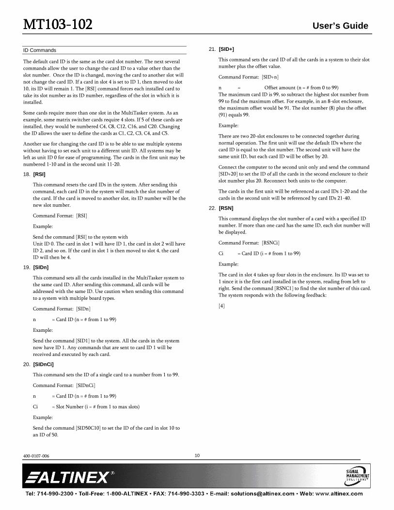
21. [SID+]
This command sets the card ID of all the cards in a system to their slot
number plus the offset value.
Command Format: [SID+n]
n = Offset amount (n = # from 0 to 99)
The maximum card ID is 99, so subtract the highest slot number from
99 to find the maximum offset. For example, in an 8-slot enclosure,
the maximum offset would be 91. The slot number (8) plus the offset
(91) equals 99.
Example:
There are two 20-slot enclosures to be connected together during
normal operation. The first unit will use the default IDs where the
card ID is equal to the slot number. The second unit will have the
same unit ID, but each card ID will be offset by 20.
Connect the computer to the second unit only and send the command
[SID+20] to set the ID of all the cards in the second enclosure to their
slot number plus 20. Reconnect both units to the computer.
The cards in the first unit will be referenced as card IDs 1-20 and the
cards in the second unit will be referenced by card IDs 21-40.
22. [RSN]
This command displays the slot number of a card with a specified ID
number. If more than one card has the same ID, each slot number will
be displayed.
Command Format: [RSNCi]
Ci = Card ID (i = # from 1 to 99)
Example:
The card in slot 4 takes up four slots in the enclosure. Its ID was set to
1 since it is the first card installed in the system, reading from left to
right. Send the command [RSNC1] to find the slot number of this card.
The system responds with the following feedback:
[4]
MTMTMTMT103103103103----102102102102 User’s Guide
400-0107-006
11
Group Commands
Group commands allow several cards to be controlled simultaneously with
a single command. Up to 8 groups (G1-G8) may be defined. These
commands apply to all cards, not only the MT103-102.
23. [WR]
This command adds cards to a group. In MultiTasker systems with
audio and video cards, the groups are typically as follows:
Group 1 = Video Cards
Group 2 = Audio Cards
Group 3 = Video and Audio Cards
Command Format: [WRCn1Cn2…Gk]
Cn = Card ID (n = slot # from 1 to max slots)
Gk = Group ID (k = # from 1-8)
Example:
Add C2, C4, and C6 to G5 by sending the command [WRC2C4C6G5].
After executing this command, G5 will consist of C2, C4, and C6.
Now add C8 to G5 by sending [WRC8G5]. C8 is added to G5, and G5
is not overwritten. View the contents of G5 by sending [RDG5] and
receiving the following feedback:
[G5=C2C4C6C8]
24. [RMC]
This command removes one or more cards from a group.
Command Format: [RMCn1Cn2…Gk]
Cn = Card ID (n= # from 1 to max slots)
Gk = Group ID (k = # from 1-8)
Example:
G5 consists of C2, C4, C6, and C8. Remove C6 and C8 by sending
[RMC6C8G5]. View the contents of G5 by sending [RDG5] and
receiving the following feedback:
[G5=C2C4]
25. [RMG]
This command deletes one or all groups.
Command Format: [RMGk]
Gk = Group ID (k = # from 1-8, * for all)
Example:
Remove all cards from G5 by sending [RMG5]. The system will return
the following feedback:
[G5=0]
Example 2:
Remove all cards from all groups, effectively deleting all groups, by
sending [RMG*]. The system will return the following feedback:
G1-G8: EMPTY
26. [RD]
This command reads and then displays the members in a group.
Command Format: [RDGk]
Gk = Group ID (k = # from 1-8)
Example:
C2, C4, and C6 make up G5. Read the member data for G5 by sending
the command [RDG5]. The system will return feedback as follows:
[G5=C2C4C6]
The feedback shows G5 and then the cards that make up G5. In this
case, G5 includes C2, C4, and C6.
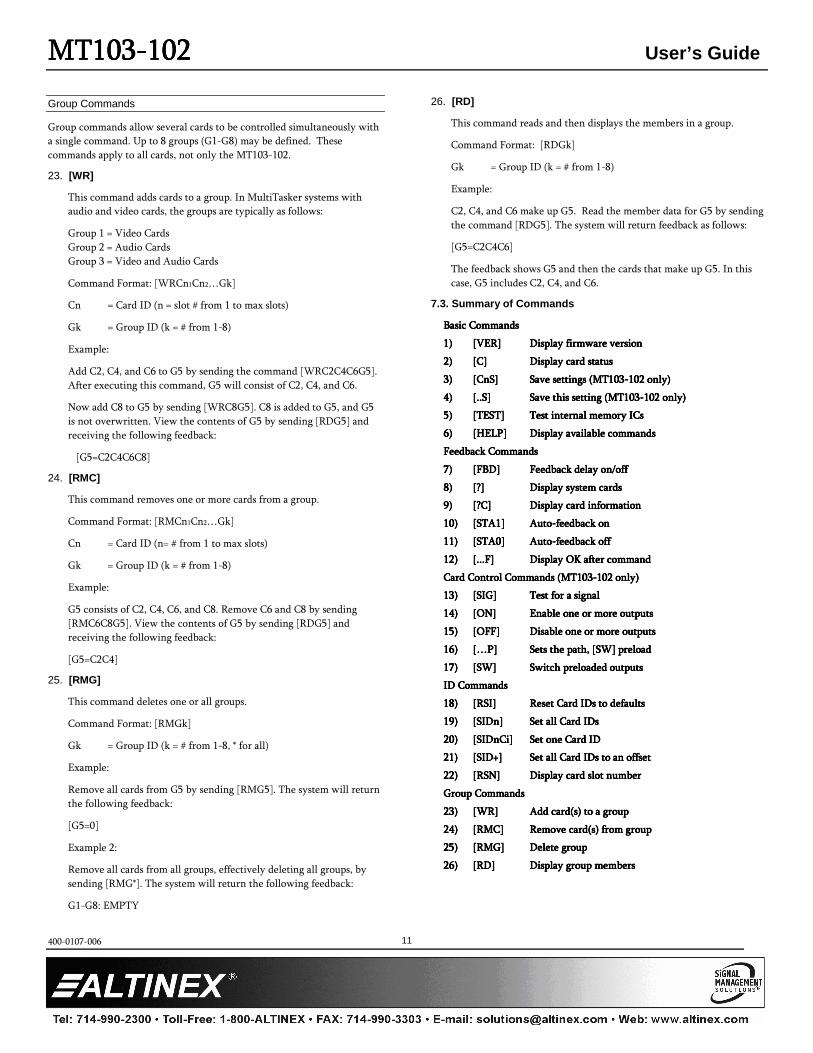
7.3. Summary of Commands
Basic CommandsBasic CommandsBasic CommandsBasic Commands
1)1)1)1) [VER][VER][VER][VER] Display firmware versionDisplay firmware versionDisplay firmware versionDisplay firmware version
2)2)2)2) [C][C][C][C] Display card statusDisplay card statusDisplay card statusDisplay card status
3)3)3)3) [CnS][CnS][CnS][CnS] Save settings (MT103Save settings (MT103Save settings (MT103Save settings (MT103----102 only)102 only)102 only)102 only)
4)4)4)4) [..S][..S][..S][..S] Save this setting (MT103Save this setting (MT103Save this setting (MT103Save this setting (MT103----102 only)102 only)102 only)102 only)
5)5)5)5) [TEST][TEST][TEST][TEST] Test internal memory ICsTest internal memory ICsTest internal memory ICsTest internal memory ICs
6)6)6)6) [HELP][HELP][HELP][HELP] Display available commandsDisplay available commandsDisplay available commandsDisplay available commands
FeFeFeFeedback Commandsedback Commandsedback Commandsedback Commands
7)7)7)7) [FBD][FBD][FBD][FBD] Feedback delay on/offFeedback delay on/offFeedback delay on/offFeedback delay on/off
8)8)8)8) [?][?][?][?] Display system cardsDisplay system cardsDisplay system cardsDisplay system cards
9)9)9)9) [?C][?C][?C][?C] Display card informationDisplay card informationDisplay card informationDisplay card information
10)10)10)10) [STA1][STA1][STA1][STA1] AutoAutoAutoAuto----feedback onfeedback onfeedback onfeedback on
11)11)11)11) [STA0][STA0][STA0][STA0] AutoAutoAutoAuto----feedback offfeedback offfeedback offfeedback off
12)12)12)12) [...F][...F][...F][...F] Display OK after commandDisplay OK after commandDisplay OK after commandDisplay OK after command
Card Control Commands (MT103Card Control Commands (MT103Card Control Commands (MT103Card Control Commands (MT103----102 only)102 only)102 only)102 only)
13)13)13)13) [SIG][SIG][SIG][SIG] Test fTest fTest fTest for a signalor a signalor a signalor a signal
14)14)14)14) [ON][ON][ON][ON] Enable one or more outputsEnable one or more outputsEnable one or more outputsEnable one or more outputs
15)15)15)15) [OFF][OFF][OFF][OFF] Disable one or more outputsDisable one or more outputsDisable one or more outputsDisable one or more outputs
16)16)16)16) […P][…P][…P][…P] Sets the path, [SW] preloadSets the path, [SW] preloadSets the path, [SW] preloadSets the path, [SW] preload
17)17)17)17) [SW][SW][SW][SW] Switch preloaded outputsSwitch preloaded outputsSwitch preloaded outputsSwitch preloaded outputs
ID CommandsID CommandsID CommandsID Commands
18)18)18)18) [RSI][RSI][RSI][RSI] Reset Card IDs to defaultsReset Card IDs to defaultsReset Card IDs to defaultsReset Card IDs to defaults
19)19)19)19) [SIDn][SIDn][SIDn][SIDn] Set all Card IDsSet all Card IDsSet all Card IDsSet all Card IDs
20)20)20)20) [SIDnCi][SIDnCi][SIDnCi][SIDnCi] Set one CSet one CSet one CSet one Card IDard IDard IDard ID
21)21)21)21) [SID+][SID+][SID+][SID+] Set all Card IDs to an offsetSet all Card IDs to an offsetSet all Card IDs to an offsetSet all Card IDs to an offset
22)22)22)22) [RSN][RSN][RSN][RSN] Display card slot numberDisplay card slot numberDisplay card slot numberDisplay card slot number
Group CommandsGroup CommandsGroup CommandsGroup Commands
23)23)23)23) [WR][WR][WR][WR] Add card(s) to a groupAdd card(s) to a groupAdd card(s) to a groupAdd card(s) to a group
24)24)24)24) [RMC][RMC][RMC][RMC] Remove card(s) from groupRemove card(s) from groupRemove card(s) from groupRemove card(s) from group
25)25)25)25) [RMG][RMG][RMG][RMG] Delete groupDelete groupDelete groupDelete group
26)26)26)26) [RD][RD][RD][RD] Display group membersDisplay group membersDisplay group membersDisplay group members
MTMTMTMT103103103103----102102102102 User’s Guide
400-0107-006
12
8. Troubleshooting Guide
We have carefully tested and found no problems in the supplied
MT103-102; however, we would like to offer suggestions for the following:
8.1 LED is Not Lit
The LED should be on and red when power is applied and there is no video
signal present. If the LED is on and green, the unit is receiving power and a
SYNC signal
Cause 1: Card cage is not plugged in.
Solution: Plug in the card cage. If the LED lights the problem is solved.
If the LED is still not on, see Cause 2.
Cause 2: Card is not plugged in all the way.
Solution: Push the card in all the way. If the LED is still not on, see
Cause 3.
Cause 3: Card cage slot has a problem.
Solution 1: Test the card in other slots of the card cage. If the slot was
damaged, the card may work in other slots. If the card works
in other slots and the LED lights, the problem is the card cage
slot. The card cage may require service, please call ALTINEX at
(714) 990-2300. If the other slots do not work and the LED is
still not on, see Solution 2.
Solution 2: Take any other known good card with an LED and verify that
the slot used is good by seeing if the other card’s LED lights in
that slot. If it lights, then the original card may be the source
of the problem. Call ALTINEX at (714) 990-2300.
8.2 No Display
Cause 1: The source has a problem.
Solution: Check the source and make sure that there is a signal present
and all source connections are correct. If the source is working
and there is still no display, see Cause 2.
Cause 2: The card output is not enabled.
Solution: Turn on the card outputs. See RS-232 accessible commands in
Section 7. If no display is present, see Cause 3.
Cause 3: Cable connections are incorrect.
Solution: Make sure that cables are properly connected. Also, make sure
that the continuity and wiring are good. If there is still no
display present, see Cause 4.
Cause 4: The display has a problem.
Solution: Make sure the display is powered and turned on. If there is
still no display, please call ALTINEX at (714) 990-2300.
8.3 Card is Not Recognized
Cause 1: The card is not recognized.
Solution: Reset the card cage by sending the [RES] command, or turning
the system power off and then on again. Send the [C]
command to see if there is communication with the card. If
there is no feedback, see Cause 2.
Cause 2: Card is not plugged in all the way.
Solution: Push the card in all the way. Reset the system and send the [C]
command. If the card is still not recognized, see Cause 3.
Cause 3: Card cage slot has a problem.
Solution 1: Test the card in other slots of the card cage. If the slot was
damaged, the card may work in other slots. If other slots work
and the card is recognized, the problem is the card cage slot.
The card cage may require service; call ALTINEX at
(714) 990-2300. If the other slots do not work, see Solution 2.
Solution 2: Take any other known good card and verify that the slot used
is good by seeing if the other car is recognized in that slot. If it
is, then the original card may be the source of the problem.
Call ALTINEX at (714) 990-2300.