Embed Size (px)
Citation preview
Hot Runner Systems
NOZZLES
CATALOGUE 2003
MT SERIES
SuperSeded
MTTR – TORPEDO TIP RETROFIT�
�
Features as per MTT, MTB, MTS, MIT,MOT etcAllows MTT retro-fitting to Sb Seriesnozzles
__________________page 1.2.5-1.2.6
MTB – TORPEDO BUSH�
�
�
�
�
�
Pinpoint gating with insertGood flow, colour changeLeaves witness ring on partProvides easy installationSaves cavity gate wear/replaceableCarbide tips available for abrasive materials
_________________page 1.2.9-1.2.10
MIB – ONE HOLE TORPEDO BUSH�
�
�
�
Features as per MTB, except for colourchangeCarbide tips available for abrasive materialsEliminates flow lines from nozzleLeaves witness ring on part
_________________page 1.2.9-1.2.10
Hot Runner Systems
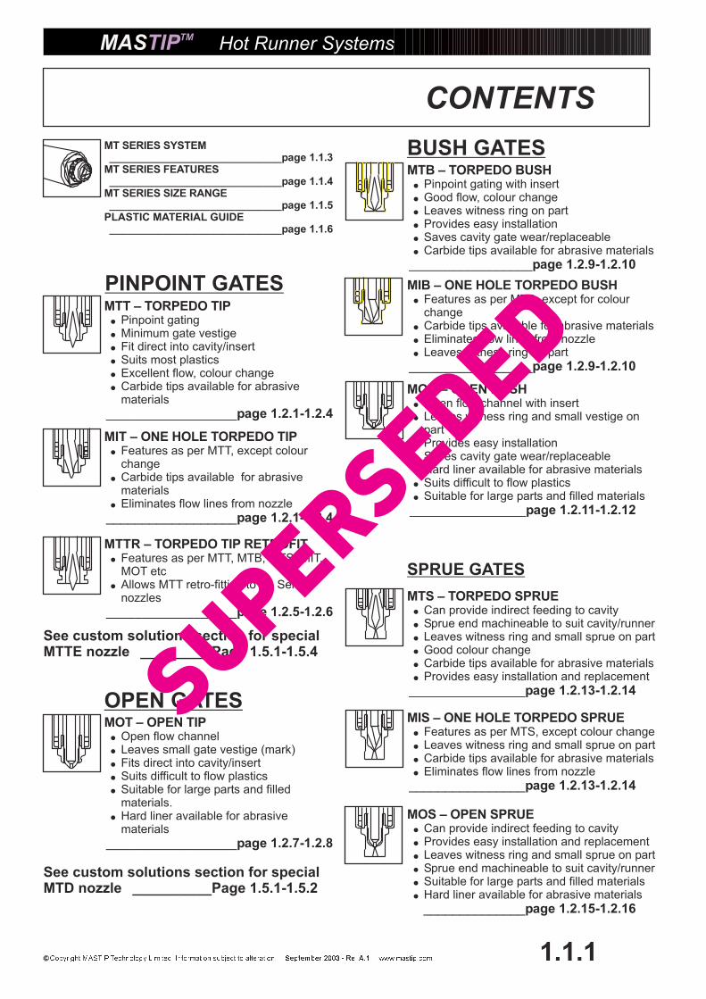
CONTENTS
1.1.1
MIS – ONE HOLE TORPEDO SPRUE�
�
�
�
Features as per MTS, except colour changeLeaves witness ring and small sprue on partCarbide tips available for abrasive materialsEliminates flow lines from nozzle
________________page 1.2.13-1.2.14
MT SERIES SYSTEM
MT SERIES FEATURES
MT SERIES SIZE RANGE
PLASTIC MATERIAL GUIDE
_____________________________page 1.1.3
_____________________________page 1.1.4
_____________________________page 1.1.5
_____________________________page 1.1.6
MTT – TORPEDO TIP�
�
�
�
�
�
Pinpoint gatingMinimum gate vestigeFit direct into cavity/insertSuits most plasticsExcellent flow, colour changeCarbide tips available for abrasivematerials
__________________page 1.2.1-1.2.4
PINPOINT GATES
SPRUE GATES
BUSH GATES
MOT – OPEN TIP�
�
�
�
�
�
Open flow channelLeaves small gate vestige (mark)Fits direct into cavity/insertSuits difficult to flow plasticsSuitable for large parts and filledmaterials.Hard liner available for abrasivematerials
__________________page 1.2.7-1.2.8
OPEN GATES
MIT – ONE HOLE TORPEDO TIP�
�
�
Features as per MTT, except colourchangeCarbide tips available for abrasivematerialsEliminates flow lines from nozzle
__________________page 1.2.1-1.2.4
See custom solutions section for specialMTTE nozzle _________Page 1.5.1-1.5.4
See custom solutions section for specialMTD nozzle __________Page 1.5.1-1.5.2
MOS – OPEN SPRUE�
�
�
�
�
�
Can provide indirect feeding to cavityProvides easy installation and replacementLeaves witness ring and small sprue on partSprue end machineable to suit cavity/runnerSuitable for large parts and filled materialsHard liner available for abrasive materials
______________page 1.2.15-1.2.16
MTS – TORPEDO SPRUE�
�
�
�
�
�
Can provide indirect feeding to cavity
Leaves witness ring and small sprue on partGood colour changeCarbide tips available for abrasive materialsProvides easy installation and replacement
cavity/runnerSprue end machineable to suit
________________page 1.2.13-1.2.14
MOB – OPEN BUSH�
�
�
�
�
�
�
Open flow channel with insertLeaves witness ring and small vestige onpartProvides easy installationSaves cavity gate wear/replaceableHard liner available for abrasive materialsSuits difficult to flow plasticsSuitable for large parts and filled materials
________________page 1.2.11-1.2.12
SuperSeded

Hot Runner Systems
1.1.2
CONTENTS
MST/MSO – TORPEDO BUSH(INCH SERIES)� Features as per MTB but in inch sizes
_____________________page 1.2.17
MSTL/MOSL – TORPEDO SPRUE(INCH SERIES)� Features as per MTS but in inch sizes
_____________________page 1.2.18
MEG – EDGE GATE�
�
�
�
Excellent technical materialsExcellent colour changeTorpedo type tip/replaceableRequires special cavity & installation
_____________________page 1.2.19
MSW – SIDE GATE�
�
For smaller center distancesSuitable only for ‘easy’ filling plastics
ie PP, PE, PS
_____________________page 1.2.20
MMG – MULTI-GATE TORPEDO�
�
�
�
Excellent technical materialsExcellent colour changeTorpedo type tip/replaceableSmall center distances
________________page 1.2.21-1.2.22
MSM – MULTI-GATE TIP�
�
Small center distancesSuitable only for ‘easy’ filling plastics i.e.PP, PE, PS
_____________________page 1.2.23
MMC-MMCF – MACHINE NOZZLE�
�
�
Open flow channelDesigned to suit any machineOptional In-built filter
________________page 1.2.26-1.2.27
MTV – TORPEDO VALVE GATE�
�
�
�
Guided valve pinExcellent flow, colour changeSuits most plasticsTapered gate pin seat
__________________page 1.3.2-1.3.3
MOV – OPEN VALVE GATE�
�
�
�
�
�
Unguided valve pinSuitable for difficult filling materialsIdeal for extra large pin sizesGood for large parts, or where flow linesare a problemHard liner available for abrasive materials.Tapered gate pin seat.
__________________page 1.3.4-1.3.5
MOVB – OPEN VALVE GATE BUSH�
�
�
�
�
�
Unguided valve pinReplaceable gateEasy installation and replacementTapered gate seatLeaves witness ring on partHard liner available for abrasive materials
__________________page 1.3.8-1.3.9
MTVB – TORPEDO VALVE GATE BUSH�
�
�
�
�
�
Guided valve pinEasy installation and replacementExcellent flow, colour changeReplaceable gateTapered gate seatLeaves witness ring on part
__________________page 1.3.6-1.3.7
ACCESSORIES
Heaters
Tips
Nuts
Thermocouples and Metal O-Rings
KEY NOZZLE COMPONENTS__________________________page 1.4.1
__________________________page 1.4.2
__________________________page 1.4.3
__________________________page 1.4.4
__________________________page 1.4.5
__________________________page 1.4.6
�
�
�
�
� Shut Off Valve Parts
MULTI TIPS
INCH SERIESMVC – STANDARD SHUT OFF VALVEASSEMBLIES�
�
�
Pneumatic or Hydraulic operationFour sizes of actuatorsStandard components
VALVE GATES
MMM – MINI MANIFOLD�
�
Completely pre-assembled partChoice of nozzles and configurations
________________page 1.2.24-1.2.25
FITTING
___________________Page 1.3.10-1.3.17Valve gate installation details.�
� Single nozzle installation details_________________________page 1.3.18
SuperSeded

Hot Runner Systems
MT SERIES SYSTEM
1.1.3
MTVBMTVMTSMTT
MOT MOB MOS MOV MOVB
MTVOB
MIT
MTVO
MTB
RFlat O-Ring
MULTI-CAVITYOPTIONS
SINGLE CAVITYOPTIONS
SuperSeded

Hot Runner Systems
MT SERIES FEATURES
1.1.4
�
�
�
�
�
�
�
�
Suits virtually any plastic materialFast colour changes (with MTT)Ideal for technical, glass filled and fiberreinforced plasticsInterchangeable, replaceable components
5 grams — 3.5 kgs capacity36 Standard nozzle lengths14 Standard gate options7 Standard nozzle series
MASTIP
Accurate temperaturecontrol and even heat
throughout Nozzlemonitored
by FeCuNi/type JThermocouple
Unique torpedo tip/gate design eliminatesstatic plastic material, resulting in excellent
colour changing and molding of eventhe most difficult technical plastics
Easy Tip replacementwith standard sockets
ref = xxx
Replaceable coilheater 230V, flat sectionvariable wattage density
Unique thermallyconductive, replaceableinner core/tip – torpedo
or open flow
Interchangeable gate optionsHardened tip holding/locating nutschange any nozzle from pinpoint to
bush, sprue
Special high temperatureretaining circlip
Fast heater replacementwithout tip/nut removal
Reflectiveheat shield
Optional locating dowelto stop rotation during
molding
Interchangeablehigh precision
tolerances
Each nozzle – singleor multi-cavity
optional flat, radiusor O-ring back
Robust H13 steelhardened body
Unique balanced material flowtorpedo -reduces injection
pressure
Tip material optionsMTT, MIT, MOT - BeCu (Std)MTTC, MTTH - Carbide tips.
MOTH - D2 liner
�
�
�Take care to accurately machinegate area! Refer to relevant pagesin catalogue for dimensions
Do not operate HCM 10 tips attemperatures over 300 C for extendedperiods.
Maximum working pressure @ for HCM 10 tips230 C -1500 bar.260 C -1400 bar.275 C -1300 bar.290 C -1200 bar.300 C -1100 bar.Maximum working pressure @400 C - 1500 bar. (Carbide)
�
SuperSeded
Hot Runner Systems
1.1.5
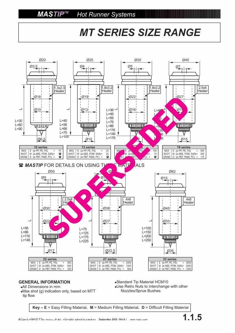
MT SERIES SIZE RANGE
�
�
Standard Tip Material HCM10Use Retro Nuts to interchange with other
Nozzles/Sprue Bushes
L=75L=125L=175L=225
Ø50
Ø9
Ø30
Ø22
Ø17
L=56L=86L=116L=146
L
2.5x4Heater
Ø50
Ø12
Ø38
Ø27
Ø22.5
L
4x6Heater
Ø62
Ø15
Ø45
Ø33
Ø26
L=100L=150L=200L=250
L
4x6Heater
33 seriesMAX E (ie PP, PE, PS) = 3500
SHOT M (ie ABS, POM, SAN)= 2500GRAM D (ie PBT, PA66, PC) = 1500
27 seriesMAX E (ie PP, PE, PS) = 2000
SHOT M (ie ABS, POM, SAN)= 1200GRAM D (ie PBT, PA66, PC) = 800
22 seriesMAX E (ie PP, PE, PS) = 900
SHOT M (ie ABS, POM, SAN)= 600GRAM D (ie PBT, PA66, PC) = 300
Ø20
Ø3.5
Ø16
Ø10
Ø6.5
L=30L=60L=90
L
1.3x2.3Heater
10 seriesMAX E (ie PP, PE, PS) = 15
SHOT M (ie ABS, POM, SAN)=GRAM D (ie PBT, PA66, PC) =
�
�
1.8x3.2Heater
Ø25
Ø4
Ø19
Ø13
Ø10
L=45L=56L=66L=75L=105
L
13 seriesMAX E (ie PP, PE, PS) = 30
SHOT M (ie ABS, POM, SAN)= 20GRAM D (ie PBT, PA66, PC) = �
Ø30
Ø5
Ø22
Ø16
Ø12
L=36L=46L=56L=76L=86L=116L=146L=176
L
1.8x3.2Heater
16 seriesMAX E (ie PP, PE, PS) = 100
SHOT M (ie ABS, POM, SAN)= 70GRAM D (ie PBT, PA66, PC) = �
Ø40
Ø7
Ø27
Ø19
Ø15
L=46L=56L=66L=76L=96L=126L=156L=186
L
2.5x4Heater
19 seriesMAX E (ie PP, PE, PS) = 500
SHOT M (ie ABS, POM, SAN)= 300GRAM D (ie PBT, PA66, PC) = 175
Key – E M D= Easy Filling Material, = Medium Filling Material, = Difficult Filling Material
FOR DETAILS ON USING THESE MATERIALS� MASTIP
GENERAL INFORMATION�
�
All Dimensions in mmMax shot (g) indication only, based on MTTtip flow
SuperSeded

Plastic MTT MTB MTS MTD MTV(O)MTVB(O) MIT MOT MOB MOS MOV MOVB MMG MSM MMM MEG MSW
PP
PE
� � � � � � � � � � � � � � � �
� � � � � � � � � � � � � � � �
�
�
� � � � � � � � � � � � � � � � �
� � � � � � � � � � � � � � � � �
� � � � � � � � � � � � � � � � �
� � � � � � � � � � � � � � � �
� � � � � � � � � � � � � � � �
� � � � � � � � � � � � � � � �
� � � � � � � � �
� � � � � � � � � � � � � � � �
� � � � � � � � � � � � � � � �
� � � � � � � � � � � � � � � �
� � � � � � � � � � � � � � � �
� � � � � � � � � � � �
� � � � � � � � � � � �
� � � � � � � � � � �
� � � � � � � � � � � �
� � � � � � � � � � � �
� � � � � � � � � � � �
� � � � � � � � � �
� � � � � � � � �
� � � � � � � � � � � � � � � �
� � � � � � � � � � � �
� � � � � � � � � � � �
� � � � � � � � � � � �
� � � � � � � � � � � � � � �
� � � � � �
� � � � � � � � � � � � �
TH
PS
SB
EVA
ABS
POM
SAN
PA6
PMMA
ASA
CAB
TPE
PBT
PA66
PC
PC/ABS
PPS
PES
PPO
PSU
PVC-soft
LCP
PEI
�
�
�
�
�
�
�
�
�
�
�
�
�
�
�
�
�
�
�
� � � �
� � � �
TH TH TH TH
TH TH TH TH
TH TH TH TH
TH TH TH TH
TH TH TH TH
TH TH TH TH
TH TH TH TH
TH TH TH TH TH TH TH
TH TH TH
TH TH TH TH
TH TH TH TH TH TH TH
Colour Change
Cosmetic Gate
Glass Fibre (GF)
Flame Ret’dant (FR)
� � � � � � �
�
� �
� � � � �
� �
Mediu
mF
illin
g
M
Hot Runner Systems
1.1.6
PLASTIC MATERIAL GUIDE
MASTIP Nozzle Selection
Difficult
Fill
ing
D
Easy
Fill
ing
E
Key: = Good, = OK, = No Good, = Tel ,� � � � MASTIP TH = Use Full Carbide or D2 tips
Recommendations OnlyContact before using D and M materials with MT 10 and MT 13 series nozzlesFor thin walled / high pressure / high speed applications contact for recommendations.
�
�
�
�
MASTIPMASTIP
This chart is designed to be a basic guide only, specific nozzle selection is dependent on theapplication and part details.Do not operate the standard HCM 10 tips at temperatures over 300 C for extended periods of time.
SuperSeded
GATE ‘C’
q J
GATE ‘B’
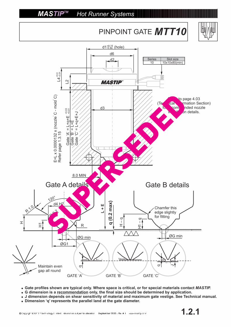
MTT10PINPOINT GATE
Hot Runner Systems
1.2.1
�
�
�
�
Gate profiles shown are typical only. Where space is critical, or for special materials contactG dimension is a only, the final size should be determined by application.J dimension depends on shear sensitivity of material and maximum gate vestige. See Technical manual.Dimension ‘q’ represents the parallel land at the gate diameter.
MASTIP.recommendation
q(0
.2m
ax)
H1
–q
H–
q
L+
E
ØG min
H1H
ØG1
ØG min
120°
R0.2R
1.0
R
GATE ‘A’
Gate A details Gate B details
d4 H7
E=
Lx
0.0
00
01
32
x(n
ozzle
C-
mo
ldC
)R
efe
rpa
ge
1.3
.15
d2L4
L2
8.0 MIN
d3
Series10
Slot size10x10x80(min)
Gate
‘A’
=L+
q+
EG
ate
‘B’=
L+
EG
ate
‘C’ =
L+
q+
E+
J
d1 (hole)
q
Chamfer thisedge slightlyfor fitting
Maintain evengap all round
d6
Refer to page 4.03(Technical Information Section)
for recommended nozzleinstallation details.
SuperSeded

MTT
Example Order — 1 x MTT10090 – O-Ring /FlatMulti 4 x MTT10090 – O-Ring/Flat
Hot Runner Systems
1.2.2
MTT10PINPOINT GATE
Flat O-RingMTT10 SERIES NOZZLES�
�
�
Use where minimum gate vestige andgood colour change are important.Ideal for high cavity tooling and wherethere is gateprofile.Not recommended for single nozzleapplications without Hot Runnermanifold.
limited room around the
SHOT
SIZE
(GRAMS) EASY MEDIUM DIFFICULT
MT10 0.5-15 � 6
� L d1 d2 d3 d4 d6 L2 L4 G G1
H
+0.0
- 0.1
H1
+0.0
- 0.1
RE@� �
� 200 C
E@� �� 250 C
MTT10030 30 20 3.5 17 6.5 17.5 8 10 10 0.8 5.7 4.7 3.5 5 0.08 0.10 115WMTT10060 60 0.16 0.20 280WMTT10090 90 0.24 0.30 400W
SuperSeded

MTT/MIT 13-33PINPOINT GATE
d2
L4
L2
d6
8.0 MIN
d3
dw
d1 (hole)10
Gate
‘A’
=L+
q+
EG
ate
‘B’=
L+
EG
ate
‘C’ =
L+
q+
E+
J
Series13,16,19,22
27,33
Slot size12x12x80(min)15x12x80(min)
MT22 -MT33
MT13 -MT19
d4 H7
Hot Runner Systems
1.2.3
90°
R
M
M–
q
H1
–q
H–
q
ØG min
H1H
ØG1
ØG min
120°
R0.2R
3.0
GATE ‘A’
q J
GATE ‘C’GATE ‘B’
Gate A details Gate B details
K (ref)
S(r
ef)
�
�
�
�
Gate profiles shown are typical only. Where space is critical, or for special materials contactG dimension is a only, the final size should be determined by application.J dimension depends on shear sensitivity of material and maximum gate vestige. See Technical manual.
MASTIP.recommendation
Dimension ‘q’ represents the parallel land at the gate diameter.
Chamfer thisedge slightlyfor fitting
q
S-
q(r
ef)
q(0
.2m
ax)
L+
E
E=
Lx
0.0
00
01
32
x(n
ozzle
C-
mo
ldC
)R
efe
rpa
ge
1.3
.15
Maintain evengap all round
Refer to page 4.03(Technical Information Section)
for recommended nozzleinstallation details.
SuperSeded
� L d1 d2 d3 d4 d6 L2 L4 dw M G G1
H
+0.0
- 0.1
H1
+0.0
- 0.1
S K RE@� T=
200 C
E@� T=
250 C
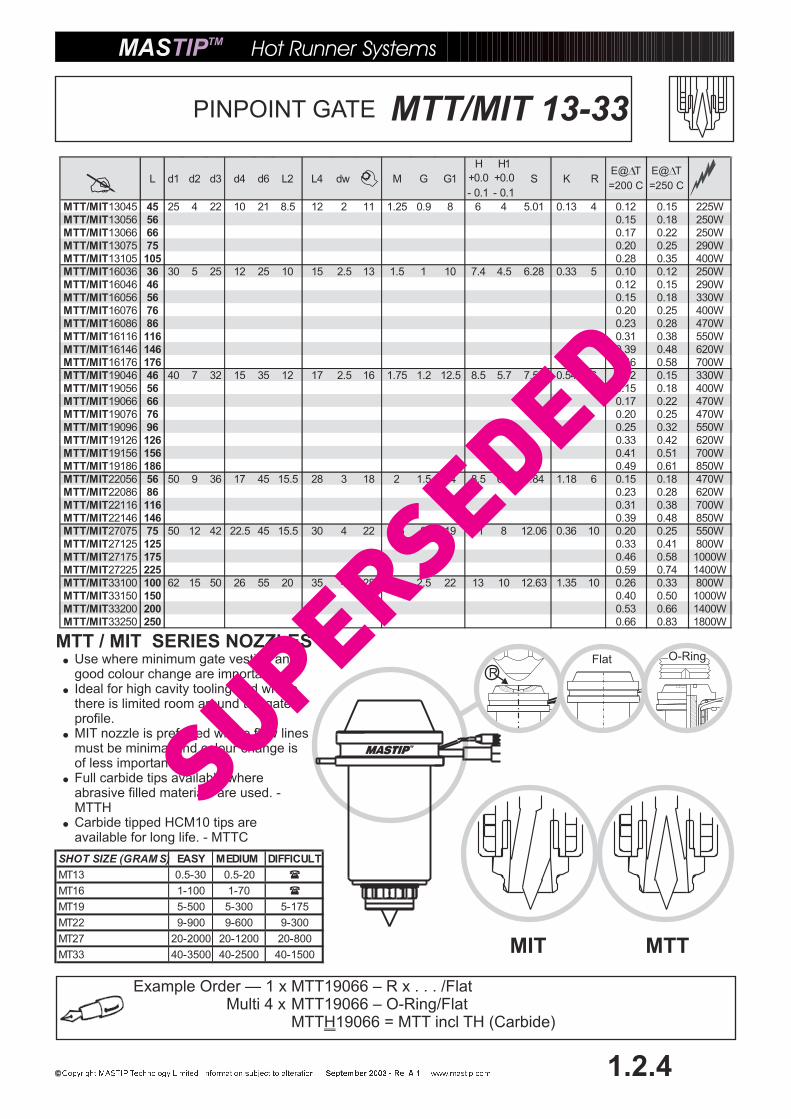
MTT/MIT13045 45 25 4 22 10 21 8.5 12 2 11 1.25 0.9 8 6 4 5.01 0.13 4 0.12 0.15 225WMTT/MIT13056 56 0.15 0.18 250WMTT/MIT13066 66 0.17 0.22 250WMTT/MIT13075 75 0.20 0.25 290WMTT/MIT13105 105 0.28 0.35 400WMTT/MIT16036 36 30 5 25 12 25 10 15 2.5 13 1.5 1 10 7.4 4.5 6.28 0.33 5 0.10 0.12 250WMTT/MIT16046 46 0.12 0.15 290WMTT/MIT16056 56 0.15 0.18 330WMTT/MIT16076 76 0.20 0.25 400WMTT/MIT16086 86 0.23 0.28 470WMTT/MIT16116 116 0.31 0.38 550WMTT/MIT16146 146 0.39 0.48 620WMTT/MIT16176 176 0.46 0.58 700WMTT/MIT19046 46 40 7 32 15 35 12 17 2.5 16 1.75 1.2 12.5 8.5 5.7 7.53 0.54 6 0.12 0.15 330WMTT/MIT19056 56 0.15 0.18 400WMTT/MIT19066 66 0.17 0.22 470WMTT/MIT19076 76 0.20 0.25 470WMTT/MIT19096 96 0.25 0.32 550WMTT/MIT19126 126 0.33 0.42 620WMTT/MIT19156 156 0.41 0.51 700WMTT/MIT19186 186 0.49 0.61 850WMTT/MIT22056 56 50 9 36 17 45 15.5 28 3 18 2 1.5 14 8.5 6.4 7.84 1.18 6 0.15 0.18 470WMTT/MIT22086 86 0.23 0.28 620WMTT/MIT22116 116 0.31 0.38 700WMTT/MIT22146 146 0.39 0.48 850WMTT/MIT27075 75 50 12 42 22.5 45 15.5 30 4 22 2.5 2 19 11 8 12.06 0.36 10 0.20 0.25 550WMTT/MIT27125 125 0.33 0.41 800WMTT/MIT27175 175 0.46 0.58 1000WMTT/MIT27225 225 0.59 0.74 1400WMTT/MIT33100 100 62 15 50 26 55 20 35 4 28 3 2.5 22 13 10 12.63 1.35 10 0.26 0.33 800WMTT/MIT33150 150 0.40 0.50 1000WMTT/MIT33200 200 0.53 0.66 1400WMTT/MIT33250 250 0.66 0.83 1800W
MIT MTT
Example Order — 1 x MTT19066 – R x . . . /FlatMulti 4 x MTT19066 – O-Ring/Flat
MTT 19066 = MTT incl TH (Carbide)H
Hot Runner Systems
1.2.4
MTT/MIT 13-33PINPOINT GATE
RFlat O-Ring
MTT / MIT SERIES NOZZLES�
�
�
�
�
Use where minimum gate vestige andgood colour change are important.Ideal for high cavity tooling and wherethere is limited room around the gateprofile.MIT nozzle is preferred where flow linesmust be minimal and colour change isof less importance.Full carbide tips available whereabrasive filled materials are used. -MTTHCarbide tipped HCM10 tips areavailable for long life. - MTTC
SHOT SIZE (GRAM S) EASY MEDIUM DIFFICULT
MT13 0.5-30 0.5-20 �
MT16 1-100 1-70 �
MT19 5-500 5-300 5-175
MT22 9-900 9-600 9-300
MT27 20-2000 20-1200 20-800
MT33 40-3500 40-2500 40-1500
E@ T
=200 C
E@ T
=250 C
SuperSeded

Hot Runner Systems
1.2.5
d2
L2
d6
d4 H7
8.0 MIN
d3
dw
10 d1 (hole)
MTTRPINPOINT RETRO GATE
Series13,16,19,22
Slot size12x12x80(min)
M
M–
q
H1
–q
H–
q
ØG min
H1H
ØG1
ØG min
120°
90°R
0.2R3.0
R
Gate A details Gate B details
Remove material fromstandard Sb gate profile
Conversion machiningdetail for Sb to MTT
Gate
‘A’
=L+
q+
EG
ate
‘B’=
L+
EG
ate
‘C’ =
L+
q+
E+
J
L4
q
GATE ‘A’
q J
GATE ‘C’GATE ‘B’
K (ref)
MT22 -MT33
MT13 -MT19
S(r
ef)
S-
q(r
ef)
�
�
�
�
Gate profiles shown are typical only. Where space is critical, or for special materials contactG dimension is a only, the final size should be determined by application.
Mastip.recommendation
J dimension depends on shear sensitivity of material and maximum gate vestige. See Technical manual.Dimension ‘q’ represents the parallel land at the gate diameter.
Chamfer thisedge slightlyfor fitting
q(0
.2m
ax)
L+
E
E=
Lx
0.0
00
01
32
x(n
ozzle
C-
mo
ldC
)R
efe
rpa
ge
1.3
.15
Maintain evengap all round
Refer to page 4.03(Technical Information Section)
for recommended nozzleinstallation details.
SuperSeded

�L d1 d2 d3 d4 d6 L2 L4 dw M G G1
H+0.0
- 0.1
H1+0.0
- 0.1
S K RE@� T
= 200 C
E@� T
= 250 C
MTTR13045 45 25 4 22 12.5 21 8.5 12 2 11 1.25 0.9 10 6.7 4 5.24 1.2 4 0.12 0.15 225WMTTR13056 56 0.15 0.18 250WMTTR13066 66 0.17 0.22 250WMTTR13075 75 0.20 0.25 290WMTTR13105 105 0.28 0.35 400WMTTR16036 36 30 5 25 16 25 10 15 2.5 13 1.5 1 11 8.0 4.5 6.41 0.88 5 0.10 0.12 250WMTTR16046 46 0.12 0.15 290WMTTR16056 56 0.15 0.18 330WMTTR16076 76 0.20 0.25 400WMTTR16086 86 0.23 0.28 470WMTTR16116 116 0.31 0.38 550WMTTR19046 46 40 7 32 19 35 12 17 2.5 16 1.75 1.2 14.5 9.7 5.7 7.72 1.6 6 0.12 0.15 330WMTTR19056 56 0.15 0.18 400WMTTR19066 66 0.17 0.22 470WMTTR19076 76 0.20 0.25 470WMTTR19096 96 0.25 0.32 550WMTTR19126 126 0.33 0.42 620WMTTR22056 56 50 9 36 22 45 15.5 28 3 18 2 1.5 16.5 9.9 6.4 8 2.47 6 0.15 0.18 470WMTTR22086 86 0.23 0.28 620WMTTR22116 116 0.31 0.38 700WMTTR22146 146 0.39 0.48 850W
RFlat O-Ring
Hot Runner Systems
1.2.6
NOTE: Retro nozzles are also available in the following configurations.MITR/MITRC - One hole TorpedoMTBR/MIBR(C) - Bush nut RetroMTSR/MISR(C) - Sprue nut RetroMOTR/MOTRH - Open tip RetroMOBR/MOBRH - Open bush RetroMOSR/MOSRH - Open sprue Retro
MTTRPINPOINT RETRO GATE
Example Order — 1 x MTTR19066 – R x . . . /FlatMulti 4 x MTTR19066 – O-Ring/Flat
MTTR 19066 = MTTR incl TH (Carbide)H
MTTR SERIES NOZZLES�
�
�
�
Use to allow retro-fitting of the new MTstyle nozzles into the SB style nozzlecavities.Full carbide tips are available forabrasive filled materials - MTTRH.Carbide tipped HCM10 tips are availablefor long life. - MTTRCHard liners are available for open tip forglass filled materials - MOTRH
SHOT SIZE (GRAM S) EASY MEDIUM DIFFICULT
MT13 0.5-30 0.5-20 �
MT16 1-100 1-70 �
MT19 5-500 5-300 5-175
MT22 9-900 9-600 9-300
MTTR
SuperSeded
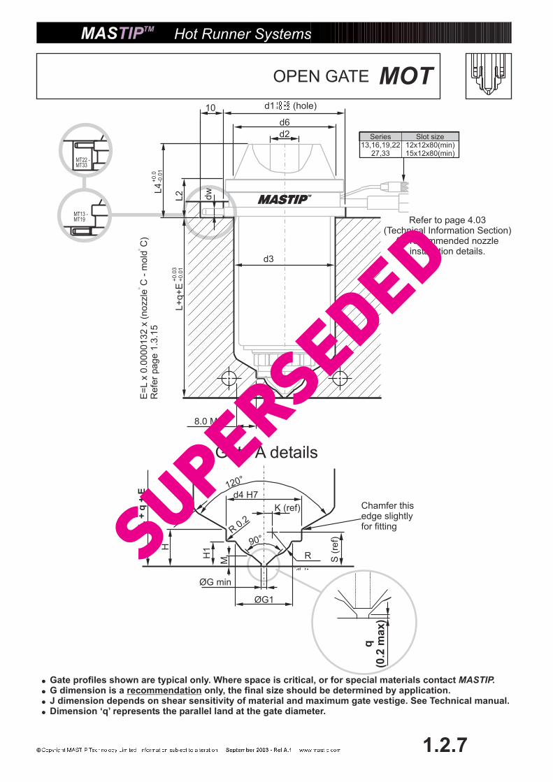
MOTOPEN GATE
d2
L2
L+
q+
E
d6
8.0 MIN
d3
dw
10 d1 (hole)
Series13,16,19,22
27,33
Slot size12x12x80(min)15x12x80(min)
Hot Runner Systems
1.2.7
H
H1
M
120°
90°
R
q(0
.2m
ax)
ØG min
ØG1
R3.0
R0.2
Gate A details
d4 H7
MT22 -MT33
MT13 -MT19
K (ref)
S(r
ef)
�
�
�
�
Gate profiles shown are typical only. Where space is critical, or for special materials contactG dimension is a only, the final size should be determined by application.J dimension depends on shear sensitivity of material and maximum gate vestige. See Technical manual.
MASTIP.recommendation
Dimension ‘q’ represents the parallel land at the gate diameter.
L4
Chamfer thisedge slightlyfor fittingL
+q
+E
E=
Lx
0.0
00
01
32
x(n
ozzle
C-
mo
ldC
)R
efe
rpa
ge
1.3
.15
Refer to page 4.03(Technical Information Section)
for recommended nozzleinstallation details.
SuperSeded

MOTOPEN GATE
RFlat O-Ring
Hot Runner Systems
1.2.8
Example Order — 1 x MOT19066 – R x . . . /FlatMulti 4 x MOT19066 – O-Ring/Flat
MOT 19066 = MOT incl OHH
�L d1 d2 d3 d4 d6 L2 L4 dw M G G1
H+0.0
-0.1
H1+0.0
- 0.1
S K RE@� T
= 200 C
E@� T
= 250 C
MOT13045 45 25 4 22 10 21 8.5 12 2 11 1.25 0.9 8 6 4 5.01 0.13 4 0.12 0.15 225WMOT13056 56 0.15 0.18 250WMOT13066 66 0.17 0.22 250WMOT13075 75 0.20 0.25 290WMOT13105 105 0.28 0.35 400WMOT16036 36 30 5 25 12 25 10 15 2.5 13 1.5 1 10 7.4 4.5 6.28 0.33 5 0.10 0.12 250WMOT16046 46 0.12 0.15 290WMOT16056 56 0.15 0.18 330WMOT16076 76 0.20 0.25 400WMOT16086 86 0.23 0.28 470WMOT16116 116 0.31 0.38 550WMOT16146 146 0.39 0.48 620WMOT16176 176 0.46 0.58 700WMOT19046 46 40 7 32 15 35 12 17 2.5 16 1.75 1.2 12.5 8.5 5.7 7.53 0.54 6 0.12 0.15 330WMOT19056 56 0.15 0.18 400WMOT19066 66 0.17 0.22 470WMOT19076 76 0.20 0.25 470WMOT19096 96 0.25 0.32 550WMOT19126 126 0.33 0.42 620WMOT19156 156 0.41 0.51 700WMOT19186 186 0.49 0.61 850WMOT22056 56 50 9 36 17 45 15.5 28 3 18 2 1.5 14 8.5 6.4 7.84 1.18 6 0.15 0.18 470WMOT22086 86 0.23 0.28 620WMOT22116 116 0.31 0.38 700WMOT22146 146 0.39 0.48 850WMOT27075 75 50 12 42 22.5 45 15.5 30 4 22 2.5 2 19 11 8 12.06 0.36 10 0.20 0.25 550WMOT27125 125 0.33 0.41 800WMOT27175 175 0.46 0.58 1000WMOT27225 225 0.59 0.74 1400WMOT33100 100 62 15 50 26 55 20 35 4 28 3 2.5 22 13 10 12.63 1.35 10 0.26 0.33 800WMOT33150 150 0.40 0.50 1000WMOT33200 200 0.53 0.66 1400WMOT33250 250 0.66 0.83 1800W
MOT SERIES NOZZLES�
�
�
�
Use where an open flow channel isimportant to maximize flow and minimize theeffects of flow lines.MOT nozzles have a slower colour changethan the MTT and leave a small gate vestige(mark).Ideal for high cavity tooling and where thereis limited room around the gate profileA hard liner is available for abrasivematerials - MOTH. (MT19-MT33 only)
SHOT SIZE (GRAM S) EASY MEDIUM DIFFICULT
MT13 0.5-30 0.5-20 0.5-10
MT16 1-100 1-70 1-35
MT19 5-500 5-300 5-175
MT22 9-900 9-600 9-300
MT27 20-2000 20-1200 20-800
MT33 40-3500 40-2500 40-1500
MOT
SuperSeded
MT22 -MT33
MT13 -MT19
Hot Runner Systems
1.2.9
q
H
H–
q
120°
R3.0
GATE ‘A’ GATE ‘B’
Gate A details Gate B details
d4 H7
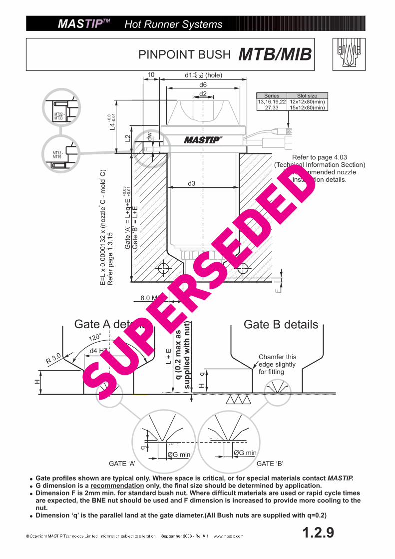
MTB/MIBPINPOINT BUSH
d1 (hole)
d6
10
8.0 MIN
dw
F
d2
L4
L2
d3
Series13,16,19,22
27,33
Slot size12x12x80(min)15x12x80(min)
Gate
‘A’
=L+
q+
EG
ate
‘B’=
L+
E
ØG minØG min
Chamfer thisedge slightlyfor fitting
�
�
�
�
Gate profiles shown are typical only. Where space is critical, or for special materials contactG dimension is a only, the final size should be determined by application.
MASTIP.recommendation
Dimension F is 2mm min. for standard bush nut. Where difficult materials are used or rapid cycle timesare expected, the BNE nut should be used and F dimension is increased to provide more cooling to thenut.Dimension ‘q’ is the parallel land at the gate diameter.(All Bush nuts are supplied with q=0.2)
L+
E
q(0
.2m
ax
as
su
pp
lied
wit
hn
ut)
E=
Lx
0.0
00
01
32
x(n
ozzle
C-
mo
ldC
)R
efe
rpa
ge
1.3
.15
Refer to page 4.03(Technical Information Section)
for recommended nozzleinstallation details.
SuperSeded

RFlat O-Ring
Hot Runner Systems
1.2.10
� L+q d1 d2 d3 d4 d6 L2 L4 dw GH
+0.0
- 0.1
E@ � T
= 200 C
E@ � T
= 250 C
M TB/M IB13045 45.2 25 4 22 10 21 8.5 12 2 11 0.9 6 0.12 0.15 225WM TB/M IB13056 56.2 0.15 0.19 250WM TB/M IB13066 66.2 0.17 0.22 250WM TB/M IB13075 75.2 0.20 0.25 290WM TB/M IB13105 105.2 0.28 0.35 400WM TB/M IB16036 36.2 30 5 25 12 25 10 15 2.5 13 1 7.4 0.10 0.12 250WM TB/M IB16046 46.2 0.12 0.15 290WM TB/M IB16056 56.2 0.15 0.19 330WM TB/M IB16076 76.2 0.20 0.25 400WM TB/M IB16086 86.2 0.23 0.28 470WM TB/M IB16116 116.2 0.31 0.38 550WM TB/M IB16146 146.2 0.39 0.48 620WM TB/M IB16176 176.2 0.47 0.58 700WM TB/M IB19046 46.2 40 7 32 15 35 12 17 2.5 16 1.2 8.5 0.12 0.15 330WM TB/M IB19056 56.2 0.15 0.19 400WM TB/M IB19066 66.2 0.17 0.22 470WM TB/M IB19076 76.2 0.20 0.25 470WM TB/M IB19096 96.2 0.25 0.32 550WM TB/M IB19126 126.2 0.33 0.42 620WM TB/M IB19156 156.2 0.41 0.52 700WM TB/M IB19186 186.2 0.49 0.61 850WM TB/M IB22056 56.2 50 9 36 17 45 15.5 28 3 18 1.5 8.5 0.15 0.19 470WM TB/M IB22086 86.2 0.23 0.28 620WM TB/M IB22116 116.2 0.31 0.38 700WM TB/M IB22146 146.2 0.39 0.48 850WM TB/M IB27075 75.2 50 12 42 22.5 45 15.5 30 4 22 2 11 0.20 0.25 550WM TB/M IB27125 125.2 0.33 0.41 800WM TB/M IB27175 175.2 0.46 0.58 1000WM TB/M IB27225 225.2 0.59 0.74 1400WM TB/M IB33100 100.2 62 15 50 26 55 20 35 4 28 2.5 13 0.26 0.33 800WM TB/M IB33150 150.2 0.40 0.50 1000WM TB/M IB33200 200.2 0.53 0.66 1400WM TB/M IB33250 250.2 0.66 0.83 1800W
MTB/MIB
MTB MIB
Example Order — 1 x MTB19066 – R x . . . /FlatMulti 4 x MTB19066 – O-Ring/Flat
MTB 19066 = MTB incl TH (Carbide)H
MTB/MIB SERIESNOZZLES�
�
�
�
�
Use where minimum gate vestige andgood colour change are important.For easy gate installation andreplacement.Use MIB nozzles when flow lines mustbe minimal and colour change is lessimportantFull carbide tips are available forabrasive filled materials. - MTBHCarbide tipped HCM10 tips availablefor long life. - MTBC
SHOT SIZE (GRAM S) EASY MEDIUM DIFFICULT
MT13 0.5-30 0.5-20 �
MT16 1-100 1-70 �
MT19 5-500 5-300 5-175
MT22 9-900 9-600 9-300
MT27 20-2000 20-1200 20-800
MT33 40-3500 40-2500 40-1500
PINPOINT BUSH
SuperSeded
d2
L4
L2
L+
q+
E
d6
8.0 MIN
d3
F
10
dw
d1 (hole)
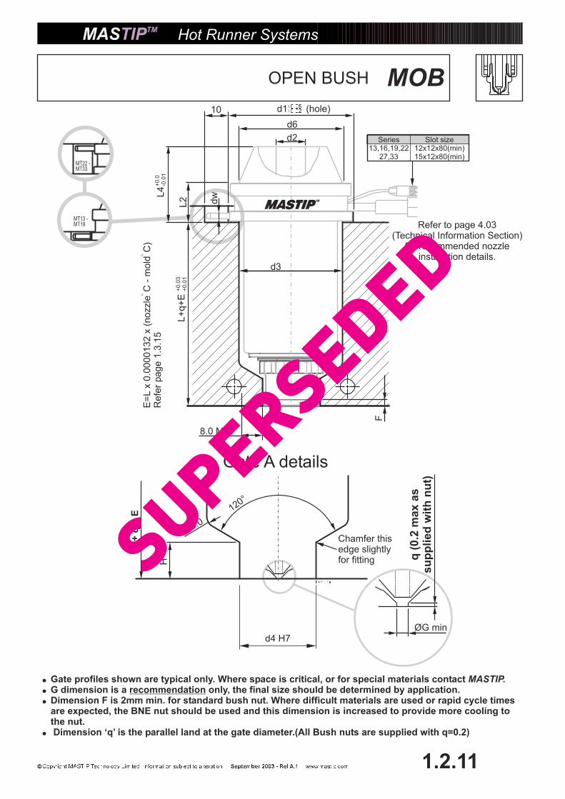
Series13,16,19,22
27,33
Slot size12x12x80(min)15x12x80(min)
Hot Runner Systems
1.2.11
H
120°
R 3.0
Gate A details
MOBOPEN BUSH
MT22 -MT33
MT13 -MT19
q(0
.2m
ax
as
su
pp
lied
wit
hn
ut)
ØG min
�
�
�
�
Gate profiles shown are typical only. Where space is critical, or for special materials contactG dimension is a only, the final size should be determined by application.
MASTIP.recommendation
Dimension F is 2mm min. for standard bush nut. Where difficult materials are used or rapid cycle timesare expected, the BNE nut should be used and this dimension is increased to provide more cooling tothe nut.Dimension ‘q’ is the parallel land at the gate diameter.(All Bush nuts are supplied with q=0.2)
Chamfer thisedge slightlyfor fitting
L+
q+
E
d4 H7
E=
Lx
0.0
00
01
32
x(n
ozzle
C-
mo
ldC
)R
efe
rpa
ge
1.3
.15
Refer to page 4.03(Technical Information Section)
for recommended nozzleinstallation details.
SuperSeded

RFlat O-Ring
Hot Runner Systems
1.2.12
MOB
Example Order — 1 x MOB19066 – R x . . . /FlatMulti 4 x MOB19066 – O-Ring/Flat
MOB 19066 = MOB incl THH
�L+q d1 d2 d3 d4 d6 L2 L4 dw G
H+0.0
-0.1
E@� T=
200 C
E@� T=
250 C
M OB13045 45.2 25 4 22 10 21 8.5 12 2 11 0.9 6 0.12 0.15 225WM OB13056 56.2 0.15 0.19 250WM OB13066 66.2 0.17 0.22 250WM OB13075 75.2 0.20 0.25 290WM OB13105 105.2 0.28 0.35 400WM OB16036 36.2 30 5 25 12 25 10 15 2.5 13 1 7.4 0.10 0.12 250WM OB16046 46.2 0.12 0.15 290WM OB16056 56.2 0.15 0.19 330WM OB16076 76.2 0.20 0.25 400WM OB16086 86.2 0.23 0.28 470WM OB16116 116.2 0.31 0.38 550WM OB16146 146.2 0.39 0.48 620WM OB16176 176.2 0.47 0.58 700WM OB19046 46.2 40 7 32 15 35 12 17 2.5 16 1.2 8.5 0.12 0.15 330WM OB19056 56.2 0.15 0.19 400WM OB19066 66.2 0.17 0.22 470WM OB19076 76.2 0.20 0.25 470WM OB19096 96.2 0.25 0.32 550WM OB19126 126.2 0.33 0.42 620WM OB19156 156.2 0.41 0.52 700WM OB19186 186.2 0.49 0.61 850WM OB22056 56.2 50 9 36 17 45 15.5 28 3 18 1.5 8.5 0.15 0.19 470WM OB22086 86.2 0.23 0.28 620WM OB22116 116.2 0.31 0.38 700WM OB22146 146.2 0.39 0.48 850WM OB27075 75.2 50 12 42 22.5 45 15.5 30 4 22 2 11 0.20 0.25 550WM OB27125 125.2 0.33 0.41 800WM OB27175 175.2 0.46 0.58 1000WM OB27225 225.2 0.59 0.74 1400WM OB33100 100.2 62 15 50 26 55 20 35 4 28 2.5 13 0.26 0.33 800WM OB33150 150.2 0.40 0.50 1000WM OB33200 200.2 0.53 0.66 1400WM OB33250 250.2 0.66 0.83 1800W
MOB SERIES NOZZLES�
�
�
�
Use where an open flow channel isimportant to maximize flow and minimizeeffects of flow lines.MOB nozzles have a slower colour changethan the MTB and leaves a small gatevestige (mark).Use for easy gate installation andreplacement.A hard liner is available for abrasivematerials - MOBH (MT19-MT33 only)
SHOT SIZE (GRAM S) EASY MEDIUM DIFFICULT
MT13 0.5-30 0.5-20 0.5-10
MT16 1-100 1-70 1-35
MT19 5-500 5-300 5-175
MT22 9-900 9-600 9-300
MT27 20-2000 20-1200 20-800
MT33 40-3500 40-2500 40-1500 MOB
OPEN BUSH
SuperSeded

MTS/MISPINPOINT SPRUE
d2
L4
L2
d6
8.0 MIN
d3
dw
10
Series13,16,19,22
27,33
Slot size12x12x80(min)15x12x80(min)
d1 (hole)
MT22 -MT33
MT13 -MT19
Gate
‘A’
=L+
q+
EG
ate
‘D’ =
L+
q+
E–M
OD
Hot Runner Systems
1.2.13
Gate
A=
HG
ate
D=
H-M
OD
5m
mM
AX
MO
DIF
ICA
TIO
NA
RE
A(M
OD
)
120°
ØG minR
3.0
Gate A/D details
�
�
�
�
Gate profiles shown are typical only. Where space is critical, or for special materials contactG dimension is a only, the final size should be determined by application.
Mastip.recommendation
Dimension F is 2mm min. for standard sprue nut. Where difficult materials are used or rapid cycle timesare expected, the SNE nut should be used and this dimension is increased to provide more cooling tothe nut.Dimension ‘q’ is the parallel land at the gate diameter.(q=0.2 maximum)
F
Chamfer thisedge slightlyfor fitting
Gate
A=
L+
q+
EG
ate
D=
L+
q+
E-M
OD
The extra 5mm on endof the sprue tip shouldbe modified to suit tooldesign, or used to add asprue to a standard gateprofile
d4 H7
E=
Lx
0.0
00
01
32
x(n
ozzle
C-
mo
ldC
)R
efe
rpa
ge
1.3
.15
Refer to page 4.03(Technical Information Section)
for recommended nozzleinstallation details.
SuperSeded
MTS/MIS
RFlat O-Ring
Hot Runner Systems
1.2.14
MTS MIS
�L+q d1 d2 d3 d4 d6 L2 L4 dw G
H+0.0
- 0.1
E@ � T=
200 C
E@ � T=
250 C
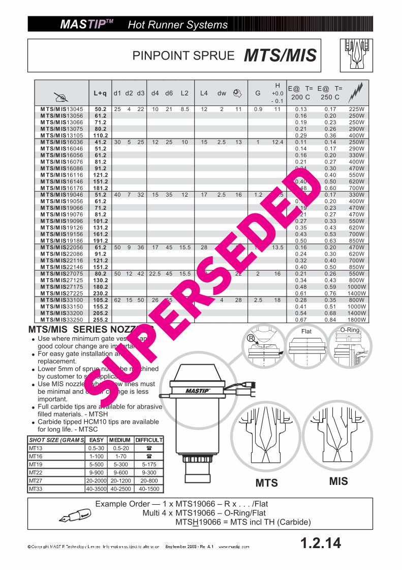
M TS/M IS13045 50.2 25 4 22 10 21 8.5 12 2 11 0.9 11 0.13 0.17 225WM TS/M IS13056 61.2 0.16 0.20 250WM TS/M IS13066 71.2 0.19 0.23 250WM TS/M IS13075 80.2 0.21 0.26 290WM TS/M IS13105 110.2 0.29 0.36 400WM TS/M IS16036 41.2 30 5 25 12 25 10 15 2.5 13 1 12.4 0.11 0.14 250WM TS/M IS16046 51.2 0.14 0.17 290WM TS/M IS16056 61.2 0.16 0.20 330WM TS/M IS16076 81.2 0.21 0.27 400WM TS/M IS16086 91.2 0.24 0.30 470WM TS/M IS16116 121.2 0.32 0.40 550WM TS/M IS16146 151.2 0.40 0.50 620WM TS/M IS16176 181.2 0.48 0.60 700WM TS/M IS19046 51.2 40 7 32 15 35 12 17 2.5 16 1.2 13.5 0.14 0.17 330WM TS/M IS19056 61.2 0.16 0.20 400WM TS/M IS19066 71.2 0.19 0.23 470WM TS/M IS19076 81.2 0.21 0.27 470WM TS/M IS19096 101.2 0.27 0.33 550WM TS/M IS19126 131.2 0.35 0.43 620WM TS/M IS19156 161.2 0.43 0.53 700WM TS/M IS19186 191.2 0.50 0.63 850WM TS/M IS22056 61.2 50 9 36 17 45 15.5 28 3 18 1.5 13.5 0.16 0.20 470WM TS/M IS22086 91.2 0.24 0.30 620WM TS/M IS22116 121.2 0.32 0.40 700WM TS/M IS22146 151.2 0.40 0.50 850WM TS/M IS27075 80.2 50 12 42 22.5 45 15.5 30 4 22 2 16 0.21 0.26 550WM TS/M IS27125 130.2 0.34 0.43 800WM TS/M IS27175 180.2 0.48 0.59 1000WM TS/M IS27225 230.2 0.61 0.76 1400WM TS/M IS33100 105.2 62 15 50 26 55 20 35 4 28 2.5 18 0.28 0.35 800WM TS/M IS33150 155.2 0.41 0.51 1000WM TS/M IS33200 205.2 0.54 0.68 1400WM TS/M IS33250 255.2 0.67 0.84 1800W
Example Order — 1 x MTS19066 – R x . . . /FlatMulti 4 x MTS19066 – O-Ring/Flat
MTS 19066 = MTS incl TH (Carbide)H
MTS/MIS SERIES NOZZLES�
�
�
�
�
�
Use where minimum gate vestige andgood colour change are important.For easy gate installation andreplacement.Lower 5mm of sprue nut to be machinedby customer to suit application.Use MIS nozzles where flow lines mustbe minimal and colour change is lessimportant.Full carbide tips are available for abrasivefilled materials. - MTSHCarbide tipped HCM10 tips are availablefor long life. - MTSC
SHOT SIZE (GRAM S) EASY MEDIUM DIFFICULT
MT13 0.5-30 0.5-20 �
MT16 1-100 1-70 �
MT19 5-500 5-300 5-175
MT22 9-900 9-600 9-300
MT27 20-2000 20-1200 20-800
MT33 40-3500 40-2500 40-1500
PINPOINT SPRUE
SuperSeded

5m
mM
AX
120°
ØG minR
3.0
Gate A/D details
d2
L2
d6
8.0 MIN
d3
dw
10 d1 (hole)
Series13,16,19,22
27,33
Slot size12x12x80(min)15x12x80(min)
Gate
‘A’
=L+
q+
EG
ate
‘D’ =
L+
q+
E-M
OD
Hot Runner Systems
1.2.15
MOSOPEN SPRUE
MT22 -MT33
MT13 -MT19
d4 H7
�
�
�
�
Gate profiles shown are typical only. Where space is critical, or for special materials contactG dimension is a only, the final size should be determined by application.
MASTIP.recommendation
Dimension F is 2mm min. for standard sprue nut. Where difficult materials are used or rapid cycle timesare expected, the SNE nut should be used and this dimension is increased to provide more cooling tothe nut.Dimension ‘q’ is the parallel land at the gate diameter.(q=0.2 maximum)
L4
Chamfer thisedge slightlyfor fitting
F
E=
Lx
0.0
00
01
32
x(n
ozzle
C-
mo
ldC
)R
efe
rpa
ge
1.3
.15
MO
DIF
ICA
TIO
NA
RE
A(M
OD
)
Gate
A=
L+
q+
EG
ate
D=
L+
q+
E-M
OD
Gate
A=
HG
ate
D=
H-M
OD
The extra 5mm on endof the sprue tip shouldbe modified to suit tooldesign, or used to add asprue to a standard gateprofile
Refer to page 4.03(Technical Information Section)
for recommended nozzleinstallation details.
SuperSeded
RFlat O-Ring
Hot Runner Systems
1.2.16
� L+q d1 d2 d3 d4 d6 L2 L4 dw GH
+0.0
-0.1
E@� T
= 200 C
E@� T
= 250 C
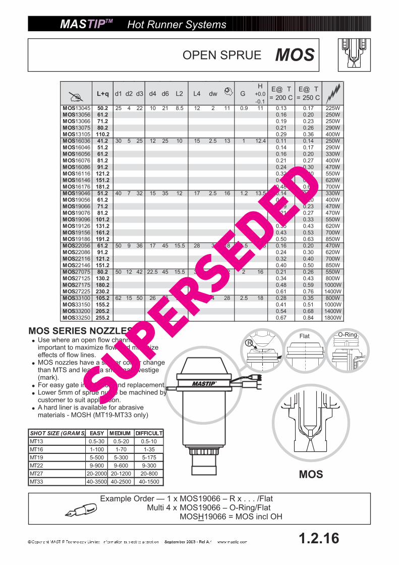
MOS13045 50.2 25 4 22 10 21 8.5 12 2 11 0.9 11 0.13 0.17 225WMOS13056 61.2 0.16 0.20 250WMOS13066 71.2 0.19 0.23 250WMOS13075 80.2 0.21 0.26 290WMOS13105 110.2 0.29 0.36 400WMOS16036 41.2 30 5 25 12 25 10 15 2.5 13 1 12.4 0.11 0.14 250WMOS16046 51.2 0.14 0.17 290WMOS16056 61.2 0.16 0.20 330WMOS16076 81.2 0.21 0.27 400WMOS16086 91.2 0.24 0.30 470WMOS16116 121.2 0.32 0.40 550WMOS16146 151.2 0.40 0.50 620WMOS16176 181.2 0.48 0.60 700WMOS19046 51.2 40 7 32 15 35 12 17 2.5 16 1.2 13.5 0.14 0.17 330WMOS19056 61.2 0.16 0.20 400WMOS19066 71.2 0.19 0.23 470WMOS19076 81.2 0.21 0.27 470WMOS19096 101.2 0.27 0.33 550WMOS19126 131.2 0.35 0.43 620WMOS19156 161.2 0.43 0.53 700WMOS19186 191.2 0.50 0.63 850WMOS22056 61.2 50 9 36 17 45 15.5 28 3 18 1.5 13.5 0.16 0.20 470WMOS22086 91.2 0.24 0.30 620WMOS22116 121.2 0.32 0.40 700WMOS22146 151.2 0.40 0.50 850WMOS27075 80.2 50 12 42 22.5 45 15.5 30 4 22 2 16 0.21 0.26 550WMOS27125 130.2 0.34 0.43 800WMOS27175 180.2 0.48 0.59 1000WMOS27225 230.2 0.61 0.76 1400WMOS33100 105.2 62 15 50 26 55 20 35 4 28 2.5 18 0.28 0.35 800WMOS33150 155.2 0.41 0.51 1000WMOS33200 205.2 0.54 0.68 1400WMOS33250 255.2 0.67 0.84 1800W
MOS
Example Order — 1 x MOS19066 – R x . . . /FlatMulti 4 x MOS19066 – O-Ring/Flat
MOS 19066 = MOS incl OHH
MOS SERIES NOZZLES�
�
�
�
�
Use where an open flow channel isimportant to maximize flow and minimizeeffects of flow lines.MOS nozzles have a slower colour changethan MTS and leave a small gate vestige(mark).For easy gate installation and replacement.Lower 5mm of sprue nut to be machined bycustomer to suit application.A hard liner is available for abrasivematerials - MOSH (MT19-MT33 only)
SHOT SIZE (GRAM S) EASY MEDIUM DIFFICULT
MT13 0.5-30 0.5-20 0.5-10
MT16 1-100 1-70 1-35
MT19 5-500 5-300 5-175
MT22 9-900 9-600 9-300
MT27 20-2000 20-1200 20-800
MT33 40-3500 40-2500 40-1500MOS
OPEN SPRUE
2
SuperSeded

RFlat O-Ring
MST/MSO SERIES NOZZLES�
�
�
These are imperial sized nozzles.The MST/MSO nozzles have similarcharacteristics to the MTB/MOB.Bush Nut allows for easy gateinstallation and are replaceable to allowfor gate wear.
Hot Runner Systems
1.2.17
�L+q d4
E@� T=
200 C
E@� T=
250 C
MST19137 1.375 0.750 0.0036 0.0045 330W
MST19187 1.875 0.0050 0.0062 400W
MST19237 2.375 0.0063 0.0078 470W
MST19287 2.875 0.0076 0.0095 550W
MST19337 3.375 0.0089 0.0111 550W
MST19387 3.875 0.0102 0.0128 620W
MST19437 4.375 0.0116 0.0144 620W
MST25137 1.375 1.000 0.0036 0.0045 330W
MST25187 1.875 0.0050 0.0062 400W
MST25237 2.375 0.0063 0.0078 470W
MST25287 2.875 0.0076 0.0095 550W
MST25337 3.375 0.0089 0.0111 550W
MST25387 3.875 0.0102 0.0128 620W
MST25437 4.375 0.0116 0.0144 620W
d4” H7
+0
.00
15
+0
.00
05
Ø2.0” (hole)
Ø1.732”
Ø0.315”
L+
q+
E
0.1
575”
0.5
”x
0.5
”x
3.2
5”
Ø1.18”
1.0
”
0.6
25”
0.31” MIN
0.0
79”
R0.118”
Example Order —Multi 4 x MST25137 – O-Ring/Flat
MST/MSOINCH SERIES PINPOINTGATE & OPEN BUSH
0.39”
�
�
0.079” gate dimension is a only, the final size should be determined by application.Dimension q represents the parallel land at the gate diameter.
recommendation(MST/MSO are supplied with q=0.008”
=0.7086”
MSO
q(0
.008”
MA
X)
Ø0.079”(min)
MST
q(0
.008”
MA
X)
Ø0.079”(min)
SHOT SIZE
(GRAM S) EASY M EDIUM DIFFICULT
MST/MSO 5-500 5-300 5-175
Chamfer thisedge slightlyfor fitting
All sizes are in inches
E=
Lx
0.0
00
01
32
x(n
ozzle
C-
mo
ldC
)R
efe
rpa
ge
1.3
.15
Refer to page 4.03(Technical Information Section)
for recommended nozzleinstallation details.
E@ T
=200 C
E@ T
=250 C
SuperSeded

Example Order —Multi 4 x MSTL25137 – O-Ring/Flat
Refer to page 4.03(Technical Information Section)
for recommended nozzleinstallation details.
MSTL/MSOL SERIESNOZZLES�
�
�
�
These are imperial sized nozzles.The MSTL/MSOL have similarcharacteristics to the MTS/MOS.Sprue Nut allows for easy gateinstallation and are replaceable to allowfor gate wear.The lower 0.25” of the sprue nut is to bemachined by the customer.
Hot Runner Systems
1.2.18
�L+q d4
E@� T=
200 C
E@� T=
250 C
MSTL19137 1.625 0.750 0.0043 0.0054 330W
MSTL19187 2.125 0.0056 0.0070 400W
MSTL19237 2.625 0.0069 0.0087 470W
MSTL19287 3.125 0.0083 0.0103 550W
MSTL19337 3.625 0.0096 0.0120 550W
MSTL19387 4.125 0.0109 0.0136 620W
MSTL19437 4.625 0.0122 0.0153 620W
MSTL25137 1.625 1.000 0.0043 0.0054 330W
MSTL25187 2.125 0.0056 0.0070 400W
MSTL25237 2.625 0.0069 0.0087 470W
MSTL25287 3.125 0.0083 0.0103 550W
MSTL25337 3.625 0.0096 0.0120 550W
MSTL25387 4.125 0.0109 0.0136 620W
MSTL25437 4.625 0.0122 0.0153 620W
RFlat O-Ring
Ø2.0” (hole)
Ø1.732”
Ø0.315”
Ø1.18”
0.1
575”
0.5
”x
0.5
”x
3.2
5”
MSTL/MSOLINCH SERIES PINPOINT& OPEN SPRUE
1.0
”
0.6
25”
0.31” MIN
+0
.00
15
+0
.00
05
d4” H7
0.0
79”
R0.118”
MSTLGate D
MSOLGate D
0.39”
=0.7086”
Gate
A=
L+
q+
EG
ate
D=
L+
q+
E-M
OD
SHOT SIZE
(GRAM S) EASY M EDIUM DIFFICULT
MST/MSO 5-500 5-300 5-175
�
�
0.079” gate dimension is a only, the final size should be determined by application.recommendationDimension q represents the parallel land at the gate diameter. (q=0.008” maximum)
All sizes are in inches
Chamfer thisedge slightlyfor fitting
E=
Lx
0.0
00
01
32
x(n
ozzle
C-
mo
ldC
)R
efe
rpa
ge
1.3
.15
0.2
50”
MA
X
Ø0.079”(min)
q(0
.008”
MA
X)
0.2
50”
MA
X
Ø0.079”(min)
q(0
.008”
MA
X)
E@ T
=200 C
E@ T
=250 C
SuperSeded
2 TIP
3 TIP
4 TIP
© Copyright Mastip Technology Limited
RFlat O-Ring
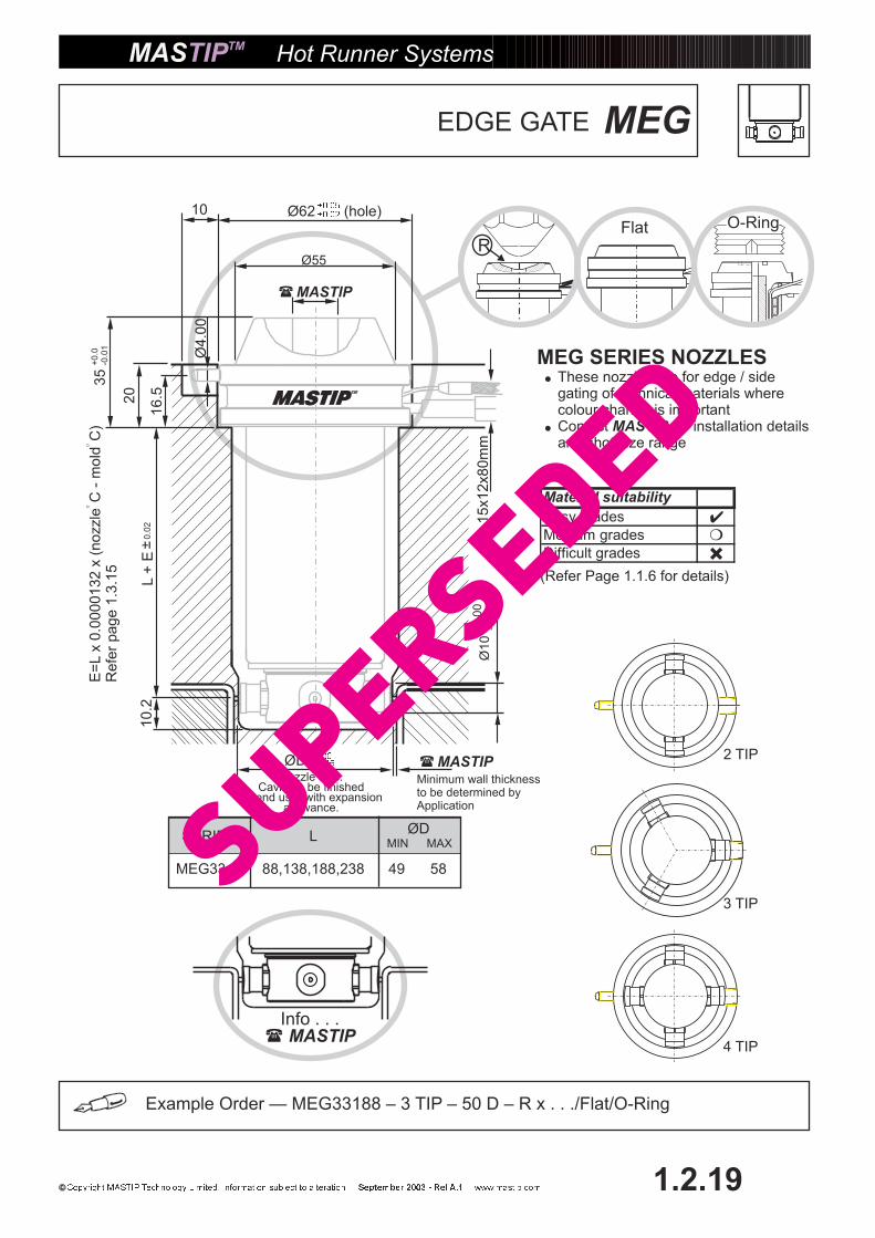
MEG SERIES NOZZLES�
�
These nozzles are for edge / sidegating of technical materials wherecolour change is importantContact for installation detailsand shot size range
MASTIP
Hot Runner Systems
1.2.19
16.5
L+
E
20
Ø55
Ø10
Ø4.0
010
35
ØDNozzle size.
Cavity to be finishedby end user with expansion
allowance.
15x12x80m
m
SERIES L
MEG33.... 88,138,188,238 49 58
ØDMIN MAX
Example Order — MEG33188 – 3 TIP – 50 D – R x . . ./Flat/O-Ring
Info . . .� MASTIP
�MASTIP
�MASTIP
Ø62 (hole)
Minimum wall thicknessto be determined byApplication
MEGEDGE GATE10.2
+0.0
0-0
.02
E=
Lx
0.0
00
01
32
x(n
ozzle
C-
mo
ldC
)R
efe
rpa
ge
1.3
.15
(Refer Page 1.1.6 for details)
Material suitability
�
�
�
Easy grades
Medium grades
Difficult grades
SuperSeded

dw
MT27,MT33
MT19–MT22
REF – Page 1.2.3 - 1.2.4MTT 19, 22, 27, 33
d1, d3, d6, L2, L3, dw
Example Order — MSW19066 – 3 TIP – 17 D – R x . . ./Flat/O-Ring
SERIES L
MSW19... 16 18.5
MSW22... 18 21.5
MSW27... 21 26.5
MSW33... 25 32.5
46,6696,126
56,86116,146
75,125175,225
100,150200,250
D
L+
E±0.0
2
ØD ±0.02
© Copyright Mastip Technology Limited
Minimum thicknessto be determined byapplication
MSWSIDE GATE
RFlat O-Ring
Series19,2227,33
Slot size12x12x80(min)15x12x80(min)
120
3 TIP
1 TIP 2 TIP
4 TIP
ØD ±0.02
ØD ±0.02ØD ±0.02
ØD ±0.02
Info . . .MASTIP�
Hot Runner Systems
1.2.20
�MASTIP
�MASTIP
MSW SERIES NOZZLES�
�
These nozzles are for edge / sidegating of easy filling materials wherecolour change is important.notContact for installationdetails and shot sizes
MASTIP
Nozzle size.Cavity to be finished
by end user with expansionallowance.
E=
Lx
0.0
00
01
32
x(n
ozzle
C-
mo
ldC
)R
efe
rpa
ge
1.3
.15
(Refer Page 1.1.6 for details)
Material suitability
�
�
�
Easy grades
Medium grades
Difficult grades
SuperSeded
Info . . .� MASTIP
FOR DETAILSON SPECIAL LENGTHS� MASTIP
RFlat O-Ring
PCD
MIN=18, MAX=20
PCD
MIN=16, MAX=20
PCD
MIN=15, MAX=20
16.520
Ø55
Ø4.0
0
10
Ø50
35
L+
q+
E+
0.0
3
SERIES L
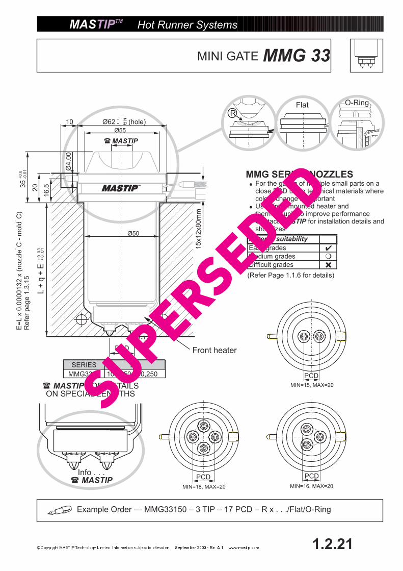
MMG33.... 100,150,200,250
Hot Runner Systems
1.2.21
Ø62 (hole)
Example Order — MMG33150 – 3 TIP – 17 PCD – R x . . ./Flat/O-Ring
15x12x80m
m
MMG 33MINI GATE
�MASTIP
MMG SERIES NOZZLES�
�
�
For the gating of multiple small parts on aclose PCD using technical materials wherecolour change is importantUses front mounted heater andthermocouple to improve performanceContact for installation details andshot sizes
MASTIP
E=
Lx
0.0
00
01
32
x(n
ozzle
C-
mo
ldC
)R
efe
rpa
ge
1.3
.15 (Refer Page 1.1.6 for details)
PCD Front heater
Material suitability
�
�
�
Easy grades
Medium grades
Difficult grades
SuperSeded

PCD
MIN=15, MAX=16
PCD
MIN=15, MAX=16
RFlat O-Ring
2.5
15.5
Ø45
Ø3.0
0
10
Ø42
20
+0
.03
SERIES L
MMG27.... 60,110,160,210
Hot Runner Systems
1.2.22
Ø50 (hole)
Example Order — MMG27060 – 3 TIP – 15 PCD – R x . . ./Flat/O-Ring
15x12x80m
m
MMG 27MINI GATE
�MASTIP
L+
q+
E
E=
Lx
0.0
00
01
32
x(n
ozzle
C-
mo
ldC
)R
efe
rpa
ge
1.3
.15
PCD
FOR DETAILSON SPECIAL LENGTHS� MASTIP
Info . . .� MASTIP
Front heater
MMG SERIES NOZZLES�
�
�
For the gating of multiple small parts on aclose PCD using technical materials wherecolour change is importantUses front mounted heater andthermocouple to improve performanceContact for installation details andshot sizes
MASTIP
(Refer Page 1.1.6 for details)
Material suitability
�
�
�
Easy grades
Medium grades
Difficult grades
SuperSeded
Series19,2227,33
Slot size12x12x80(min)15x12x80(min)
REF – Page 1.2.3 - 1.2.4MTT 19, 22, 27 33
d1, d3, d6, L2, L3, dw
dw
MT27,MT33
MT19–MT22
RFlat O-Ring
Info . . .� MASTIP
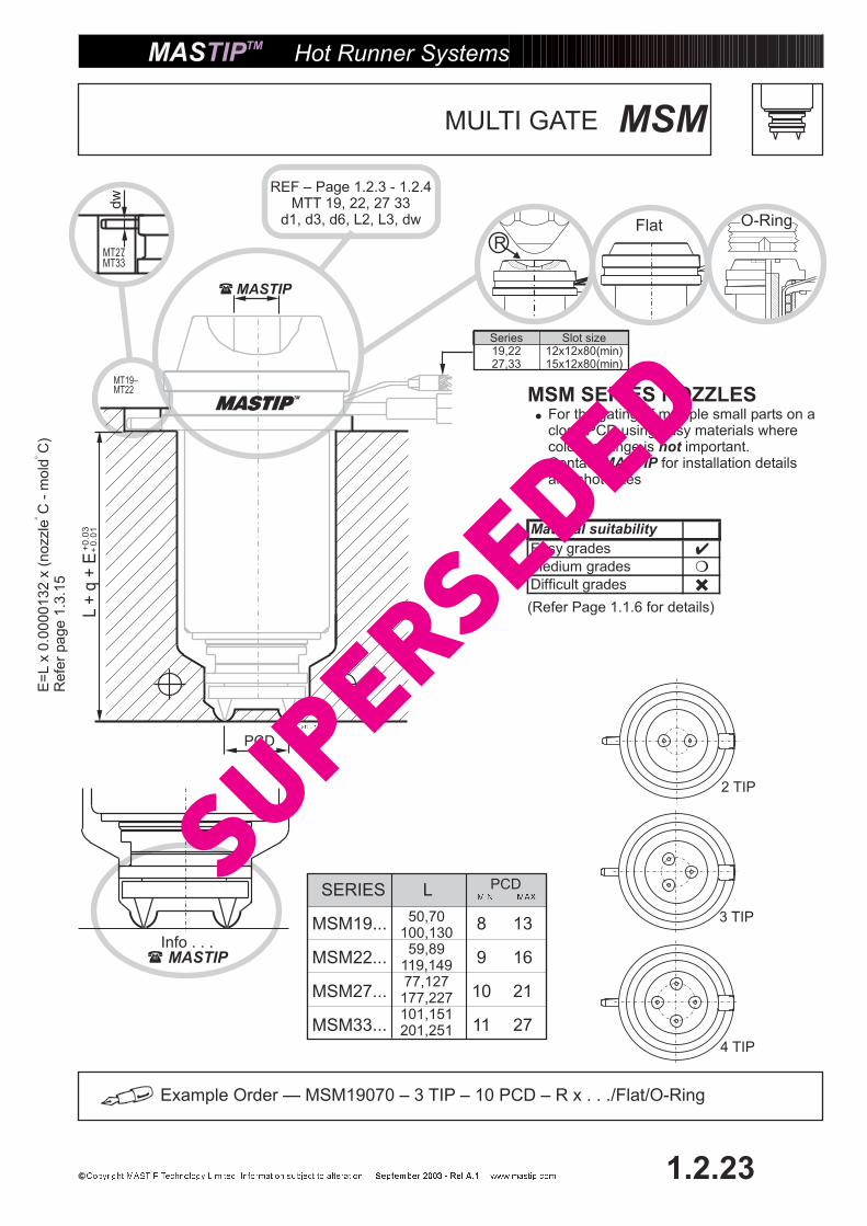
SERIES L
MSM19... 8 13
MSM22... 9 16
MSM27... 10 21
MSM33... 11 27
50,70100,13059,89
119,14977,127177,227101,151201,251
PCD
Example Order — MSM19070 – 3 TIP – 10 PCD – R x . . ./Flat/O-Ring
L+
q+
E+
0.0
3
PCD
MSM SERIES NOZZLES�
�
For the gating of multiple small parts on aclose PCD using easy materials wherecolour change is important.notContact for installation detailsand shot sizes
MASTIP
4 TIP
3 TIP
2 TIP
Hot Runner Systems
1.2.23
MSMMULTI GATE
�MASTIP
E=
Lx
0.0
00
01
32
x(n
ozzle
C-
mo
ldC
)R
efe
rpa
ge
1.3
.15
(Refer Page 1.1.6 for details)
Material suitability
�
�
�
Easy grades
Medium grades
Difficult grades
SuperSeded

Example Order — MMM13045 – 3 TIP – 40 PCD – R x . . ./Flat/O-Ring
© Copyright Mastip Technology Limited
Hot Runner Systems
1.2.24
MMMMINI MANIFOLD
Info . . .
....5 tip – 6 tip ....� MASTIP
PCD2 TIP
PCD3 TIP
PCD4 TIP
5
6
20
12
50
L3Counter boredholes forclampingto mold.
Nozzle wire exits.Refer Nozzle fittingfor detailsPage 1.2.1-1.2.4D
3
D1
D2
Ø30
L2
D (Hole size)+0.04+0.02
L1
L+
q+
E+
0.0
3+
0.0
1
� For dimension q refer to Nozzle details on page 1.2.1 - 1.2.4
E=
Lx
0.0
00
01
32
x(n
ozzle
C-
mo
ldC
)R
efe
rpa
ge
1.3
.15
PCD
Nozzle PCD Nozzle L1 L2 L3 D D1 D2 D3 POWER SERIES MAX MIN PCD MIN PCD MIN PCD
Less than (<) 40mm MT10 16 50 70 80 90 6-8 108 500W PCD 2 TIP 3 TIP 4 TIP
MT13 18 6-10 MT 10 58 30 30 32
MT16 21 6-10
Greater than (> =) 40mm MT10 16 50 80 90 100 6-8 118 600W MT 13 55 35 35 40
MT13 18 6-10
MT16 21 6-10 MT 16 50 39 39 46
SuperSeded
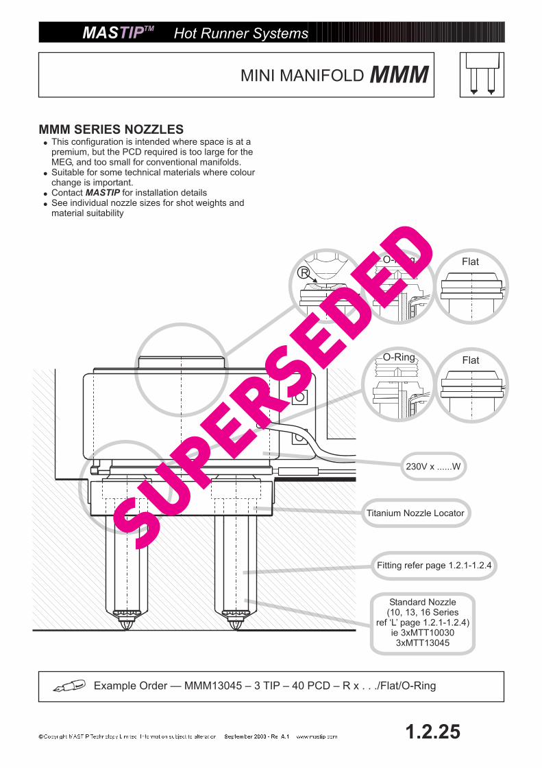
Titanium Nozzle Locator
Fitting refer page 1.2.1-1.2.4
230V x ......W
Standard Nozzle(10, 13, 16 Series
ref ‘L’ page 1.2.1-1.2.4)ie 3xMTT100303xMTT13045
O-Ring Flat
R
O-Ring Flat
Example Order — MMM13045 – 3 TIP – 40 PCD – R x . . ./Flat/O-Ring
© Copyright Mastip Technology Limited
Hot Runner Systems
1.2.25
MMMMINI MANIFOLD
MMM SERIES NOZZLES�
�
�
�
This configuration is intended where space is at apremium, but the PCD required is too large for theMEG, and too small for conventional manifolds.Suitable for some technical materials where colourchange is important.Contact for installation detailsSee individual nozzle sizes for shot weights andmaterial suitability
MASTIP
SuperSeded

KEY DESCRIPTION PCS
1 NOZZLE BODY SPECIAL 1
2 NOZZLE TIP SPECIAL 1
3 HEATER (NOT SHOWN) MT33xxxH 1
4 HEATER COVER MT33xxxHC 1
5 CIRCLIP MT3300C 1
6 THERMOCOUPLE (NOT SHOWN) MT6015TC 1
MMC & MMCF�
�
Machine Nozzles are based on the MT33 seriesnozzles and share some interchangeable partssuch as heaters, thermocouple, heater cover andcirclip.To order the following details and dimensions mustbe provided.
R1
Example Order — MMC33100D1= 8mm R1 = 19mm,D2=12,D3=25mmThread = M45 x3, L2= 40mmL3=35mm,L4=5mm,A/F=40mm
1
2
OL L2
30
4
644.5
A/F
5 4 3
TH
RE
AD
D3
D2
L4L3
Hot Runner Systems
1.2.26
MMCMACHINE NOZZLE
Ø33,4
D1
POWER OL L2 L3 L4 D1 D2 D3 THREAD R1 A/FMMC33100 800W 159
MMC33150 1000W 209
MMC33200 1400W 259
MMC33250 1800W 309
M50
or
2”
Max.T
hre
ad
Internal profile can be altered to suit molding machine
SuperSeded
1
2
Hot Runner Systems
1.2.27
MMCFMACHINE NOZZLE FILTER
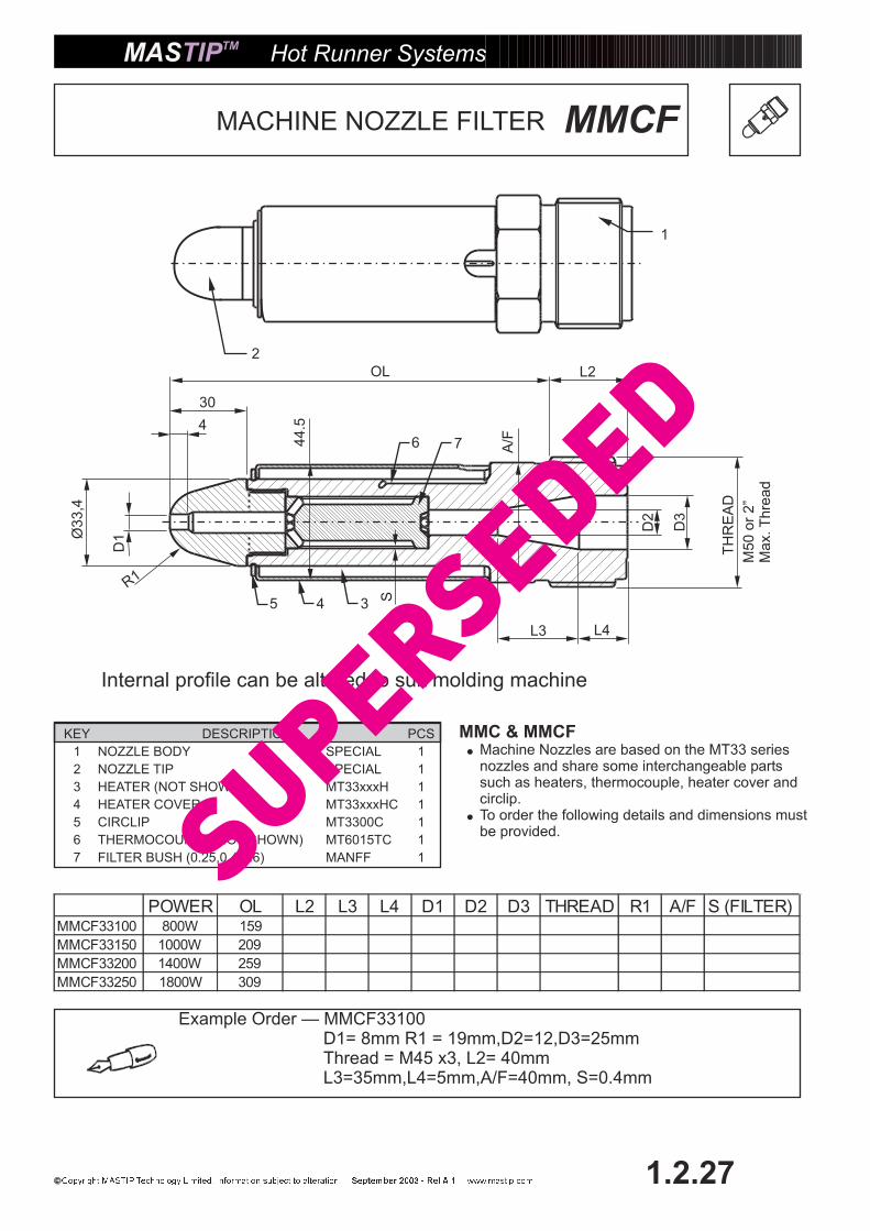
KEY DESCRIPTION PCS
1 NOZZLE BODY SPECIAL 1
2 NOZZLE TIP SPECIAL 1
3 HEATER (NOT SHOWN) MT33xxxH 1
4 HEATER COVER MT33xxxHC 1
5 CIRCLIP MT3300C 1
6 THERMOCOUPLE (NOT SHOWN) MT6015TC 1
7 FILTER BUSH (0.25,0.4,0.6) MANFF 1
POWER OL L2 L3 L4 D1 D2 D3 THREAD R1 A/F S (FILTER)MMCF33100 800W 159
MMCF33150 1000W 209
MMCF33200 1400W 259
MMCF33250 1800W 309
Ø33,4
D1
R1
44.5
5 4
30
4
OL L2
6 7
L4L3
3
D2
A/F
TH
RE
AD
D3
S
Example Order — MMCF33100D1= 8mm R1 = 19mm,D2=12,D3=25mmThread = M45 x3, L2= 40mmL3=35mm,L4=5mm,A/F=40mm, S=0.4mm
M50
or
2”
Max.T
hre
ad
MMC & MMCF�
�
Machine Nozzles are based on the MT33 seriesnozzles and share some interchangeable partssuch as heaters, thermocouple, heater cover andcirclip.To order the following details and dimensions mustbe provided.
Internal profile can be altered to suit molding machine
SuperSeded

MASTIP VALVE SYSTEMS
PNEUMATICCYLINDER
HYDRAULICCYLINDER
Hot Runner Systems
1.3.1
STANDARD.VALVE
ASSEMBLY
SuperSeded
d2
L2
d6
d4 H7
8.0 MIN
d3
L+
E
d1 (hole)
dw
10
H
H1
M
N
120°
90°
R3.0
R0.
2
R
G1
ØG min
40°
P+0.5
P
Hot Runner Systems
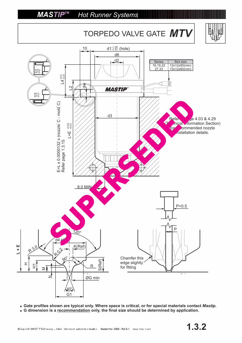
1.3.2
MTVTORPEDO VALVE GATE
Series16,19,22
27,33
Slot size12x12x80(min)15x12x80(min)MT22 -
MT33
MT13 -MT19
K(Ref)
S(R
ef)
�
�
Gate profiles shown are typical only. Where space is critical, or for special materials contactG dimension is a only, the final size should be determined by application.
Mastip.recommendation
L4
Chamfer thisedge slightlyfor fitting
L+
E
E=
Lx
0.0
00
01
32
x(n
ozzle
C-
mo
ldC
)R
efe
rpa
ge
1.3
.15
Refer to page 4.03 & 4.29(Technical Information Section)
for recommended nozzleinstallation details.
SuperSeded
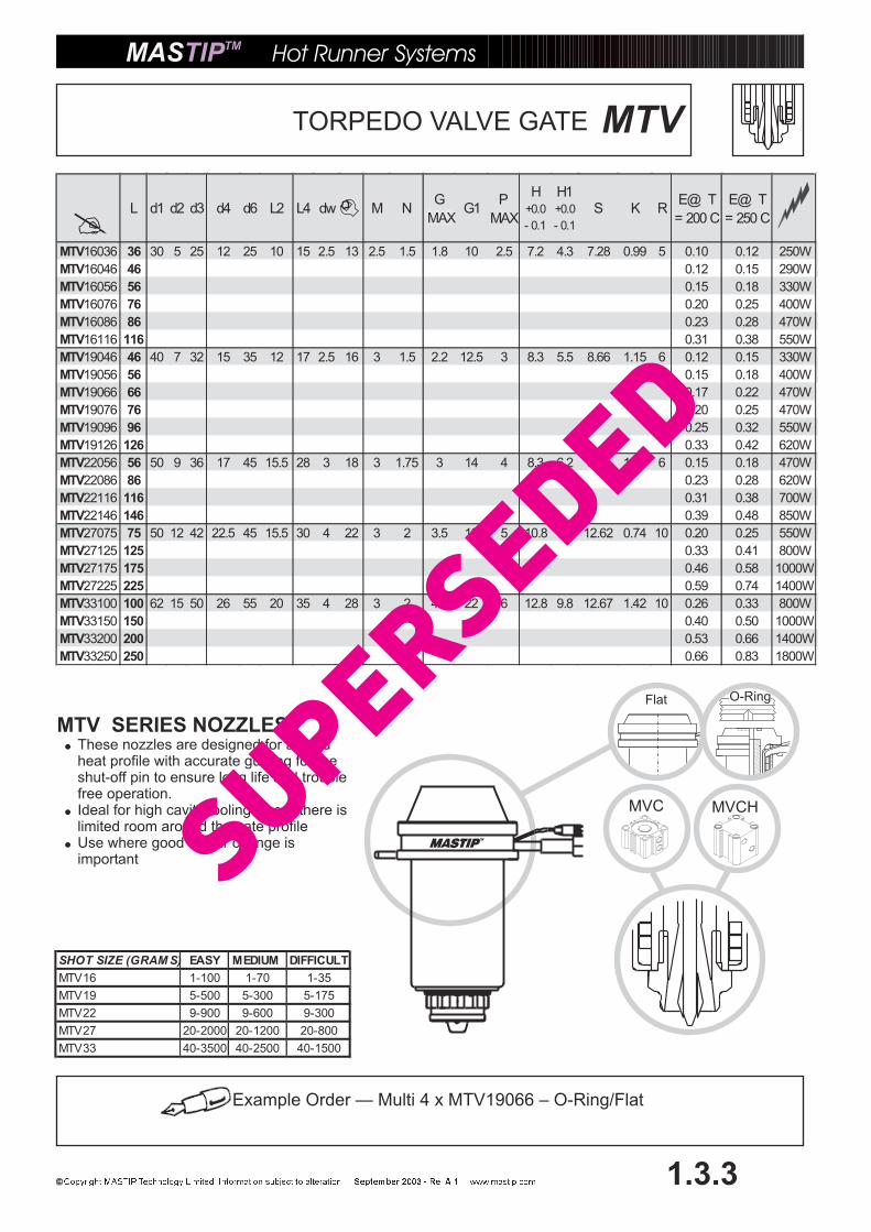
�L d1 d2 d3 d4 d6 L2 L4 dw M N
G
MING1
P
MAX
H+0.0
- 0.1
H1+0.0
- 0.1
S K RE@� T
= 200 C
E@� T
= 250 C
MTV16036 36 30 5 25 12 25 10 15 2.5 13 2.5 1.5 1.8 10 2.5 7.2 4.3 7.28 0.99 5 0.10 0.12 250W
MTV16046 46 0.12 0.15 290W
MTV16056 56 0.15 0.18 330W
MTV16076 76 0.20 0.25 400W
MTV16086 86 0.23 0.28 470W
MTV16116 116 0.31 0.38 550W
MTV19046 46 40 7 32 15 35 12 17 2.5 16 3 1.5 2.2 12.5 3 8.3 5.5 8.66 1.15 6 0.12 0.15 330W
MTV19056 56 0.15 0.18 400W
MTV19066 66 0.17 0.22 470W
MTV19076 76 0.20 0.25 470W
MTV19096 96 0.25 0.32 550W
MTV19126 126 0.33 0.42 620W
MTV22056 56 50 9 36 17 45 15.5 28 3 18 3 1.75 3 14 4 8.3 6.2 8.71 1.55 6 0.15 0.18 470W
MTV22086 86 0.23 0.28 620W
MTV22116 116 0.31 0.38 700W
MTV22146 146 0.39 0.48 850W
MTV27075 75 50 12 42 22.5 45 15.5 30 4 22 3 2 3.5 19 5 10.8 7.8 12.62 0.74 10 0.20 0.25 550W
MTV27125 125 0.33 0.41 800W
MTV27175 175 0.46 0.58 1000W
MTV27225 225 0.59 0.74 1400W
MTV33100 100 62 15 50 26 55 20 35 4 28 3 2 4.5 22 6 12.8 9.8 12.67 1.42 10 0.26 0.33 800W
MTV33150 150 0.40 0.50 1000W
MTV33200 200 0.53 0.66 1400W
MTV33250 250 0.66 0.83 1800W
Flat O-Ring
Example Order — Multi 4 x MTV19066 – O-Ring/Flat
Hot Runner Systems
1.3.3
MTV
MVC MVCH
MTV SERIES NOZZLES�
�
These nozzles are designed for a goodheat profile with accurate guiding for theshut-off pin to ensure long life and troublefree operation.
Use where good colour change isimportant
� Ideal for high cavity tooling where there islimited room around the gate profile
SHOT SIZE (GRAM S) EASY MEDIUM DIFFICULT
MTV16 1-100 1-70 1-35
MTV19 5-500 5-300 5-175
MTV22 9-900 9-600 9-300
MTV27 20-2000 20-1200 20-800
MTV33 40-3500 40-2500 40-1500
TORPEDO VALVE GATE
MAX
SuperSeded

d2
L2
d6
d4 H7
8.0 MIN
d3
L+
E
dw
10 d1 (hole)
Hot Runner Systems
1.3.4
MOVOPEN VALVE GATEH
H1
M
N
120°
R3.0
R
G1
ØG min
40°
R0.
2
P
P+0.5
Series16,19,22
27,33
Slot size12x12x80(min)15x12x80(min)
K(Ref)
S(R
ef)90°
MT22 -MT33
MT13 -MT19
Chamfer thisedge slightlyfor fitting
�
�
Gate profiles shown are typical only. Where space is critical, or for special materials contactG dimension is a only, the final size should be determined by application.
Mastip.recommendation
L4
L+
E
E=
Lx
0.0
00
01
32
x(n
ozzle
C-
mo
ldC
)R
efe
rpa
ge
1.3
.15
Refer to page 4.03 & 4.29(Technical Information Section)
for recommended nozzleinstallation details.
SuperSeded
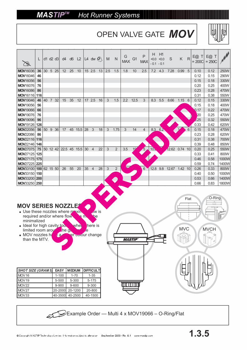
�L d1 d2 d3 d4 d6 L2 L4 dw M N
G
MING1
P
MAX
H+0.0
- 0.1
H1+0.0
- 0.1
S K RE@� T
= 200C
E@� T
= 250C
MOV16036 36 30 5 25 12 25 10 15 2.5 13 2.5 1.5 1.8 10 2.5 7.2 4.3 7.28 0.99 5 0.10 0.12 250W
MOV16046 46 0.12 0.15 290W
MOV16056 56 0.15 0.18 330W
MOV16076 76 0.20 0.25 400W
MOV16086 86 0.23 0.28 470W
MOV16116 116 0.31 0.38 550W
MOV19046 46 40 7 32 15 35 12 17 2.5 16 3 1.5 2.2 12.5 3 8.3 5.5 8.66 1.15 6 0.12 0.15 330W
MOV19056 56 0.15 0.18 400W
MOV19066 66 0.17 0.22 470W
MOV19076 76 0.20 0.25 470W
MOV19096 96 0.25 0.32 550W
MOV19126 126 0.33 0.42 620W
MOV22056 56 50 9 36 17 45 15.5 28 3 18 3 1.75 3 14 4 8.3 6.2 8.71 1.55 6 0.15 0.18 470W
MOV22086 86 0.23 0.28 620W
MOV22116 116 0.31 0.38 700W
MOV22146 146 0.39 0.48 850W
MOV27075 75 50 12 42 22.5 45 15.5 30 4 22 3 2 3.5 19 5 10.8 7.8 12.62 0.74 10 0.20 0.25 550W
MOV27125 125 0.33 0.41 800W
MOV27175 175 0.46 0.58 1000W
MOV27225 225 0.59 0.74 1400W
MOV33100 100 62 15 50 26 55 20 35 4 28 3 2 4.5 22 6 12.8 9.8 12.67 1.42 10 0.26 0.33 800W
MOV33150 150 0.40 0.50 1000W
MOV33200 200 0.53 0.66 1400W
MOV33250 250 0.66 0.83 1800W
Flat O-Ring
Example Order — Multi 4 x MOV19066 – O-Ring/Flat
Hot Runner Systems
1.3.5
MOVOPEN VALVE GATE
MVC MVCH
MOV SERIES NOZZLES�
�
�
Use these nozzles where maximum flow isrequired and/or where flow lines must beminimalizedIdeal for high cavity tooling where there islimited room around the gate profileMOV nozzles have a slower colour changethan the MTV.
SHOT SIZE (GRAM S) EASY MEDIUM DIFFICULT
MOV16 1-100 1-70 1-35
MOV19 5-500 5-300 5-175
MOV22 9-900 9-600 9-300
MOV27 20-2000 20-1200 20-800
MOV33 40-3500 40-2500 40-1500
MAX
SuperSeded

d2
L2
L+
E
d6
d4 H7
8.0 MIN
d3
F
d1 (hole)
dw
10
Hot Runner Systems
1.3.6
MTVBTORPEDO VALVE BUSH
P
ØG min
40°
P+0.5
H
120°
R3.0
Series16,19,22
27,33
Slot size12x12x80(min)15x12x80(min)
�
�
�
Gate profiles shown are typical only. Where space is critical, or for special materials contactG dimension is a only, the final size should be determined by application.
Mastip.recommendation
Dimension F is 2mm min. for standard bush nut. Where difficult materials are used or rapid cycle timesare expected, the VBNE nut should be used and this dimension is increased to provide more cooling tothe nut.
MT22 -MT33
MT13 -MT19
L4
Chamfer thisedge slightlyfor fitting
L+
E
E=
Lx
0.0
00
01
32
x(n
ozzle
C-
mo
ldC
)R
efe
rpa
ge
1.3
.15
Refer to page 4.03 & 4.29(Technical Information Section)
for recommended nozzleinstallation details.
SuperSeded

�L d1 d2 d3 d4 d6 L2 L4 dw
G
MIN
P
MAX
H+0.0
-0.1
E@� T
= 200C
E@� T
= 250C
MTVB16036 36 30 5 25 12 25 10 15 2.5 13 1.8 2.5 7.2 0.10 0.12 250W
MTVB16046 46 0.12 0.15 290W
MTVB16056 56 0.15 0.18 330W
MTVB16076 76 0.20 0.25 400W
MTVB16086 86 0.23 0.28 470W
MTVB16116 116 0.31 0.38 550W
MTVB19046 46 40 7 32 15 35 12 17 2.5 16 2.2 3 8.3 0.12 0.15 330W
MTVB19056 56 0.15 0.18 400W
MTVB19066 66 0.17 0.22 470W
MTVB19076 76 0.20 0.25 470W
MTVB19096 96 0.25 0.32 550W
MTVB19126 126 0.33 0.42 620W
MTVB22056 56 50 9 36 17 45 15.5 28 3 18 3 4 8.3 0.15 0.18 470W
MTVB22086 86 0.23 0.28 620W
MTVB22116 116 0.31 0.38 700W
MTVB22146 146 0.39 0.48 850W
MTVB27075 75 50 12 42 22.5 45 15.5 30 4 22 3.5 5 10.8 0.20 0.25 550W
MTVB27125 125 0.33 0.41 800W
MTVB27175 175 0.46 0.58 1000W
MTVB27225 225 0.59 0.74 1400W
MTVB33100 100 62 15 50 26 55 20 35 4 28 4.5 6 12.8 0.26 0.33 800W
MTVB33150 150 0.40 0.50 1000W
MTVB33200 200 0.53 0.66 1400W
MTVB33250 250 0.66 0.83 1800W
Flat O-Ring
Example Order — Multi 4 x MTVB19066 – O-Ring/Flat
Hot Runner Systems
1.3.7
MTVB
MVC MVCH
MTVB SERIES NOZZLES�
�
�
These nozzles are designed for a goodheat profile, with accurate guiding forthe shut-off pin to ensure long life andtrouble free operation.For easy gate installation andreplacement.Use where good colour change isimportant
SHOT SIZE (GRAM S) EASY MEDIUM DIFFICULT
MTVB16 1-100 1-70 1-35
MTVB19 5-500 5-300 5-175
MTVB22 9-900 9-600 9-300
MTVB27 20-2000 20-1200 20-800
MTVB33 40-3500 40-2500 40-1500
TORPEDO VALVE BUSH
MAX
SuperSeded
dw
10 d1 (hole)
d2
L2
L+
E
d6
d4 H7
8.0 MIN
d3
F
P+0.5
H
120°
P
ØG min
R3.0
40°
Series16,19,22
27,33
Slot size12x12x80(min)15x12x80(min)
Hot Runner Systems
1.3.8
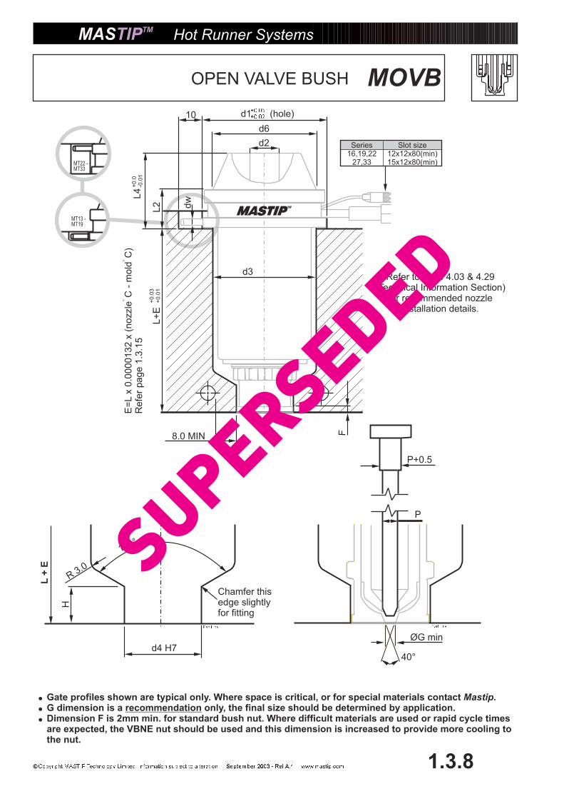
MOVBOPEN VALVE BUSH
�
�
�
Gate profiles shown are typical only. Where space is critical, or for special materials contactG dimension is a only, the final size should be determined by application.
Mastip.recommendation
Dimension F is 2mm min. for standard bush nut. Where difficult materials are used or rapid cycle timesare expected, the VBNE nut should be used and this dimension is increased to provide more cooling tothe nut.
MT22 -MT33
MT13 -MT19
L4
Chamfer thisedge slightlyfor fitting
L+
E
E=
Lx
0.0
00
01
32
x(n
ozzle
C-
mo
ldC
)R
efe
rpa
ge
1.3
.15
Refer to page 4.03 & 4.29(Technical Information Section)
for recommended nozzleinstallation details.
SuperSeded

Flat O-Ring
� L d1 d2 d3 d4 d6 L2 L4 dwG
MIN
P
MAX
H+0.0
- 0.1
E@� T
= 200 C
E@� T
= 250 C
MOVB16036 36 30 5 25 12 25 10 15 2.5 13 1.8 2.5 7.2 0.10 0.12 250W
MOVB16046 46 0.12 0.15 290W
MOVB16056 56 0.15 0.18 330W
MOVB16076 76 0.20 0.25 400W
MOVB16086 86 0.23 0.28 470W
MOVB16116 116 0.31 0.38 550W
MOVB19046 46 40 7 32 15 35 12 17 2.5 16 2.2 3 8.3 0.12 0.15 330W
MOVB19056 56 0.15 0.18 400W
MOVB19066 66 0.17 0.22 470W
MOVB19076 76 0.20 0.25 470W
MOVB19096 96 0.25 0.32 550W
MOVB19126 126 0.33 0.42 620W
MOVB22056 56 50 9 36 17 45 15.5 28 3 18 3 4 8.3 0.15 0.18 470W
MOVB22086 86 0.23 0.28 620W
MOVB22116 116 0.31 0.38 700W
MOVB22146 146 0.39 0.48 850W
MOVB27075 75 50 12 42 22.5 45 15.5 30 4 22 3.5 5 10.8 0.20 0.25 550W
MOVB27125 125 0.33 0.41 800W
MOVB27175 175 0.46 0.58 1000W
MOVB27225 225 0.59 0.74 1400W
MOVB33100 100 62 15 50 26 55 20 35 4 28 4.5 6 12.8 0.26 0.33 800W
MOVB33150 150 0.40 0.50 1000W
MOVB33200 200 0.53 0.66 1400W
MOVB33250 250 0.66 0.83 1800W
MOVB
Example Order — Multi 4 x MOVB19066 – O-Ring/Flat
Hot Runner Systems
1.3.9
MVC MVCH
MOVB SERIES NOZZLES�
�
�
Use these nozzles where maximum flow isrequired and/or where flow lines must beminimalized.For easy gate installation andreplacement.MOVB nozzles have a slower colourchange than the MTVB.
SHOT SIZE (GRAM S) EASY MEDIUM DIFFICULT
MTV16 1-100 1-70 1-35
MTV19 5-500 5-300 5-175
MTV22 9-900 9-600 9-300
MTV27 20-2000 20-1200 20-800
MTV33 40-3500 40-2500 40-1500
OPEN VALVE BUSH
MAX
SuperSeded

Hot Runner Systems
1.3.10
Backing plate
Cylinder
Titanium spacer
Steel spacer
Shut off pin retainer
Shut off pin
Shut off pin Bush
Half nut
VALVE GATE ACTUATOR SELECTION
Pneumatic Actuation Hydraulic Actuation
Nozzle Assembly Code Pin Size Stroke Nozzle Assembly Code Pin Size Stroke
MTV16 MVC5235-2.5 2.5 5 MTV16 MVCH2505-2.5 2.5 5
MOV16 MOV16 MVCH2505-2.5 5
MTV19 MVC5235-3 3 5 MTV19 MVCH2505-3 3 5
MOV19 MOV19 MVCH2505-3 5
MTV22 MVC7746-4 4 10 MTV22 MVCH2505-4 4 5
MOV22 MOV22 MVCH2510-4 10
MTV27 MVC7746-5 5 10 MTV27 MVCH2505-5 5 5
MOV27 MOV27 MVCH2510-5 10
MTV33 MVC7746-6 6 10 MTV33 MVCH2505-6 6 5
MOV33 MOV33 MVCH2510-6 10
SuperSeded

MVC5235
Hot Runner Systems
1.3.11
© Copyright Mastip Technology Limited
Example Order — MVC 5235 ASSEMBLYTo suit MTV16/MOV16/MTVB16 etc. nozzles
45
.5
Ø22 MIN
60
+0
.3+
0.2
80+0.3+0.2
=66=
=56=
=5
6=
POCKET FOR
CYLINDER
4 HOLES DRILL
& TAP
M6 X 15MM
24
RE
F
=4
0=
6.0
0.0
0-0
.02
15
.00
29
.0
14
69
.50
29
.5
18" BSPT
R4.0M
AX
X(R
EF
ER
MA
NIF
OL
D
DIM
EN
SIO
N)
L+
L4+
E
OV
ER
ALL
PIN
LE
NG
TH
=L+
L4+
E+
X+
15.0
0+
2.0
PNEUMATIC
Installation details
SuperSeded

MVC7746
Hot Runner Systems
1.3.12
Example Order — MVC 7746 ASSEMBLYTo suit MTV33/MOV33/MTVB33 etc. nozzles
R5.0 MAX6
.00.0
0-0
.02
16
.5
37
57
.0
88
.00
14" BSPT
36
.0 Ø24 MIN
OV
ER
AL
LP
INLE
NG
TH
86
+0
.3+
0.2
=6
0=
=8
2=
POCKET FOR
CYLINDER
110+0.3+0.2
=92=
=82=
4 HOLES DRILL
& TAP
M8 X 15 DEEP
15
.00
30
RE
F
PNEUMATIC
X(R
EF
ER
MA
NIF
OL
D
DIM
EN
SIO
N)
L+
L4+
E
L+
L4+
E+
X+
15.0
0+
4.5
Installation details
SuperSeded

For MOV22-33 series valve gate nozzles refer to pages 1.3.16 - 1.3.17
MVC2505H
Hot Runner Systems
1.3.13
Example Order — MVC-2505 ASSEMBLYTo suit MTV16-MTV19 nozzles
58
.0+
0.3
+0
.2
80.0+0.3+0.2
86
.00
39
18
1/8" BSP
30
.0
R5M
ax
OV
ER
AL
LP
INLE
NG
TH
=
61
=54=
=65.0=
Ø24 min.
6.0
0.0
0-0
.02
4 HOLES
DRILL & TAP
M6 X 15 DEEP
POCKET FOR
CYLINDER
15
.00
=5
4=
=3
6=
HYDRAULIC
X(R
EF
ER
MA
NIF
OL
D
DIM
EN
SIO
N)
L+
L4+
E
L+
L4+
E+
X+
15.0
0+
3.5
Installation details
SuperSeded

MVC2510H
Hot Runner Systems
1.3.14
Example Order — MVC-2510 ASSEMBLYTo suit MTV22-MTV33 nozzles
80.0+0.3+0.2
96
.00
44
18
1/8" BSP
35
.0
R5
Max
OV
ER
AL
LP
INLE
NG
TH
=
66
=54=
=65.0=
Ø24 min.
6.0
0.0
0-0
.02
4 HOLES
DRILL & TAP
M6 X 15 DEEP
POCKET FOR
CYLINDER
15
.00
=5
4=
=3
6=
58
.0+
0.3
+0.2
HYDRAULIC
X(R
EF
ER
MA
NIF
OL
D
DIM
EN
SIO
N)
L+
L4+
E
L+
L4+
E+
X+
15.0
0+
3.5
Installation details
SuperSeded

Hot Runner Systems
1.3.15
MT SERIES – SINGLE NOZZLEEXPANSION CALCULATION
E = L x 0.0000132 x (nozzle C-mold C)To calculate E (Temperature expansion)
3. Multiply by the working temperature of the the emperature.(the temperature)
4. This gives the E value to calculate the depth of the nozzle cavity.Using this value at the working temperature of the nozzle, the front of the tip will move into correctposition relative to the gate opening.
L=36mmq= 0.2mmHot Nozzle temp = 230 deg. C Total Depth =Mold Temperature = 40 deg. C
1. Take the L dimension from catalogue for the nozzle.2 Multiply by 0.0000132 (expansion factor).
E= 36mm x 0.0000132 x (230 C - 40 C)E = 0.09mm
.nozzle mold tminus
difference
Example
L+q+E in mold = 36.29mm
MA
X.
4m
m
MASTIP
MIN 1mm
Tota
ldepth
=L+
q+
E
Radius to Customer Specification
SuperSeded

MT... ONpage 1.4.4
Hot Runner Systems
1.4.1
ACCESSORIES
Example Order — Replacement heater for MTT27075Order: MT27075H
MT... TTpage 1.4.3
MT... TCpage 1.4.5
MT... Hpage 1.4.2
MT... B
MT... C
MT... HC
MT 27075 71234 MT 27075 71234
Mastip ComponentCode
Diameter of theNozzle
‘L’ Length
Production JobCode
TIP & NUT OPTIONS
TIP NUT TYPES
OPEN
(ONT)
BUSH
(BN)
BUSH FULL
CONTACT
(BNE)
SPRUE
(SN)
SPRUE FULL
CONTACT
(SNE)
RETRO
OPEN
(RN)
RETRO
BUSH
(RB)
RETRO
SPRUE
(RS)
VALVE
BUSH
VBN
VALVE
BUSH
VBNE
VALVE
RETRO
BUSH
VRN
TT (TORPEDO TIP) � � � � � � � � � � �
IT (ONE HOLE TIP) � � � � � � � � � � �
OT (OPEN TIP) � � � � � � � � � � �
TV (TORPEDO
VALVE) � � � � � � � � � � �
OV (OPEN VALVE) � � � � � � � � � � �
HARD TIPS
TC (CARBIDE
TIPPED HMC10) � � � � � � � � � � �
TH (CARBIDE
TORPEDO TIP) � � � � � � � � � � �
ITH (CARBIDE 1
HOLE TIP) � � � � � � � � � � �
MOTH (OPEN TIP
D2 LINER) � � � � � � � � � � �
T
SuperSeded

55 MAX
1000
Flat Coil Heater
MIN
R10
35*
10 max
*This length can notbe formed.
Hot Runner Systems
1.4.2
ACCESSORIES
(V230)
MT10030H 115w
MT10060H 280w
MT10090H 400w
MT13045H 225w
MT13056H 250w
MT13066H 250w
MT13075H 290w
MT13105H 400w
MT16036H 250w
MT16046H 290w
MT16056H 330w
MT16076H 400w
MT16086H 470w
MT16116H 550w
MT16146H 620w
MT16176H 700w
MT19046H 330w
MT19056H 400w
MT19066H 470w
MT19076H 470w
MT19096H 550w
MT19126H 620w
MT19156H 700w
MT19186H 850w
MT22056H 470w
MT22086H 620w
MT22116H 700w
MT22146H 850w
MT27075H 550w
MT27125H 800w
MT27175H 1000w
MT27225H 1400w
MT33100H 800w
MT33150H 1000w
MT33200H 1400w
MT33250H 1800w
HEATERS
SuperSeded

Example Order — MT19066 TT
Hot Runner Systems
1.4.3
ACCESSORIES
TC
TH
CARBIDE
CARBIDE TIPED
HCM10
OH
D2LINER
MG
HCM10
SM
HCM10
EG
HCM10
SW
HCM10
SERIES L
MTTH, MTBH, MTSH,
MITH, MIBH, MISH
MTTC, MTBC, MTSC,
MITC, MIBC, MISC
MOTH, MOBH,
MOSH MMG MSM MEG MSW
MT13 45, 56, 66, 75, 105 � � � � � � �
MT16 36, 46, 56, 76, 86 � � � � � � �
116, 146, 176
MT19 46, 56, 66, 76, 96 � � � � � � �
126, 156, 186
MT22 56, 86, 116, 146 � � � � � � �
MT27 75, 125, 175, 225 � � � � � � �
MT33 100,150, 200, 250 � � � � � � �
TIPS
SERIES L MTT MTB MTS MIT MIB MIS MOT MOS MOB MTV MTVB MOV MOVB
MT10 30,60,90 � � � � � � � � � � � � �
MT13 45, 56, 66, 75, 105 � � � � � � � � � � � � �
MT16 36, 46, 56, 76, 86, � � � � � � � � � � � � �
116, 146, 176
MT19 46, 56, 66, 76, 96, � � � � � � � � � � � � �
126, 156, 186
MT22 56, 86, 116, 146 � � � � � � � � � � � � �
MT27 75, 125, 175, 225 � � � � � � � � � � � � �
MT33 100,150, 200, 250 � � � � � � � � � � � � �
TTHCM 10
ITHCM 10
OTHCM 10
TVHCM 10
OVHCM 10
SuperSeded
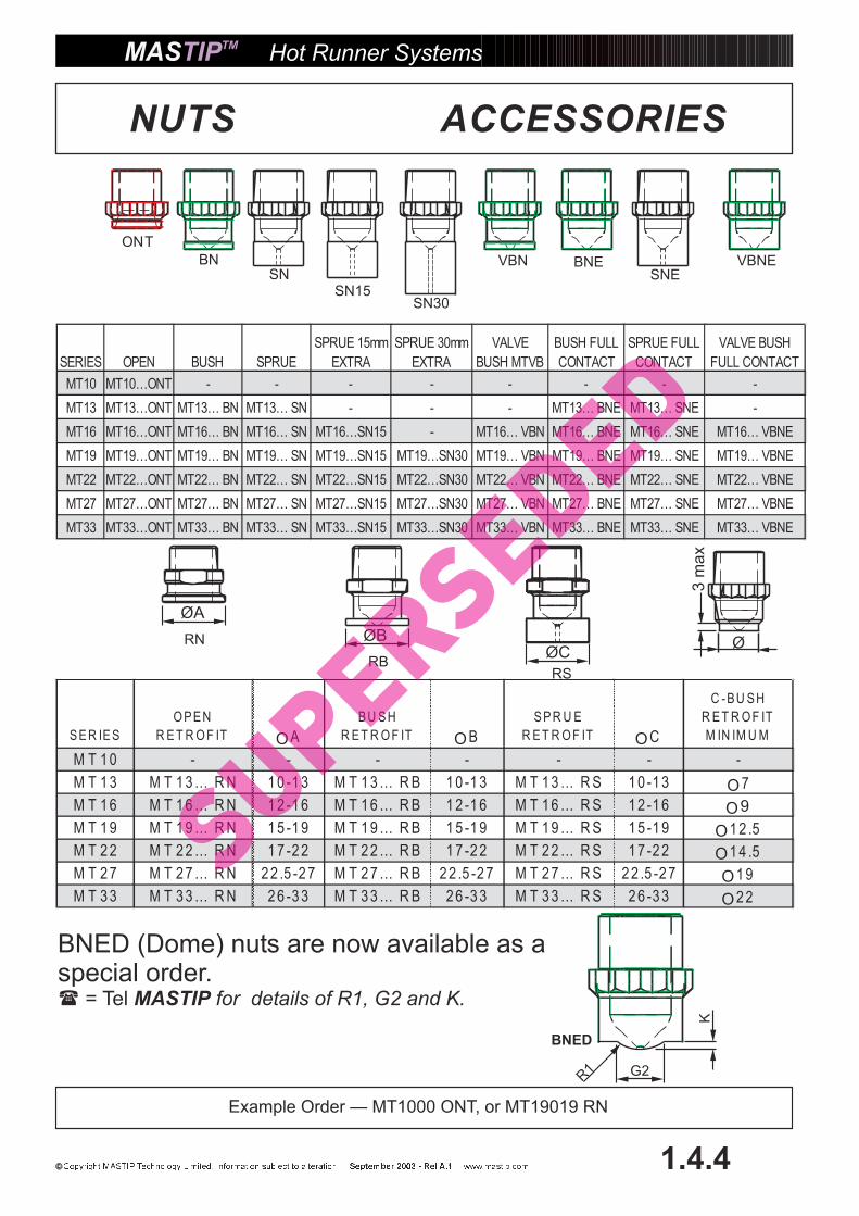
SERIES OPEN BUSH SPRUE
SPRUE 15mm
EXTRA
SPRUE 30mm
EXTRA
VALVE
BUSH MTVB
BUSH FULL
CONTACT
SPRUE FULL
CONTACT
VALVE BUSH
FULL CONTACT
MT10 MT10…ONT - - - - - - - -
MT13 MT13…ONT MT13… BN MT13… SN - - - MT13… BNE MT13… SNE -
MT16 MT16…ONT MT16… BN MT16… SN MT16…SN15 - MT16… VBN MT16… BNE MT16… SNE MT16… VBNE
MT19 MT19…ONT MT19… BN MT19… SN MT19…SN15 MT19…SN30 MT19… VBN MT19… BNE MT19… SNE MT19… VBNE
MT22 MT22…ONT MT22… BN MT22… SN MT22…SN15 MT22…SN30 MT22… VBN MT22… BNE MT22… SNE MT22… VBNE
MT27 MT27…ONT MT27… BN MT27… SN MT27…SN15 MT27…SN30 MT27… VBN MT27… BNE MT27… SNE MT27… VBNE
MT33 MT33…ONT MT33… BN MT33… SN MT33…SN15 MT33…SN30 MT33… VBN MT33… BNE MT33… SNE MT33… VBNE
Example Order — MT1000 ONT, or MT19019 RN
BNED (Dome) nuts are now available as aspecial order.� = Tel MASTIP for details of R1, G2 and K.
Hot Runner Systems
1.4.4
ACCESSORIES
ØA
ØBØC
Ø
3m
ax
RN
RBRS
SNSN15
SN30
SNEBN VBN BNE VBNE
BNED
G2
K
R1
NUTS
ONT
SER IES
O P E N
R ET R O F IT OA
BU SH
R ET R O F IT OB
SPR U E
R ET R O F IT OC
C -BU SH
R ET R O F IT
M IN IM U M
M T 1 0 - - - - - - -
M T 1 3 M T 1 3 … R N 1 0 -1 3 M T 1 3 … R B 1 0 -1 3 M T 1 3 … R S 1 0 -1 3 O7
M T 1 6 M T 1 6 … R N 1 2 -1 6 M T 1 6 … R B 1 2 -1 6 M T 1 6 … R S 1 2 -1 6 O9
M T 1 9 M T 1 9 … R N 1 5 -1 9 M T 1 9 … R B 1 5 -1 9 M T 1 9 … R S 1 5 -1 9 O1 2 .5
M T 2 2 M T 2 2 … R N 1 7 -2 2 M T 2 2 … R B 1 7 -2 2 M T 2 2 … R S 1 7 -2 2 O1 4 .5
M T 2 7 M T 2 7 … R N 2 2 .5 -2 7 M T 2 7 … R B 2 2 .5 -2 7 M T 2 7 … R S 2 2 .5 -2 7 O1 9
M T 3 3 M T 3 3 … R N 2 6 -3 3 M T 3 3 … R B 2 6 -3 3 M T 3 3 … R S 2 6 -3 3 O2 2
SuperSeded

SERIES L d
MT 6010 TC(STD) 10, 13, 16, 19 60 1.0
MT 12010 TC 10, 13, 16, 19 120 1.0
MT 6015 TC(STD) 22, 27, 33 60 1.5
MT 15015 TC 22, 27, 33 150 1.5
SERIES d1 h d2 g t
MT 500 MR 10,13,16 12.6 1.59 12.9 2.3 1.20
MT 610 MR 19, 22 17.4 1.59 17.7 2.3 1.20
MT 620 MR 27 20.7 1.59 20.9 2.3 1.20
MT 640 MR 33 27.2 1.59 27.5 2.3 1.20
THERMOCOUPLE–FeCuNi Type J
METAL O-RING
960
(+)
(–)
40.0
Ø4.0
L
d
R=3mm MINIMUM DO NOT KINK OR SQUASH!
A=0.25mm
Tmax = 600°C Tmax = 260°C Tmax = 260°C
d1
h
d2 - H10g min
R 0.4 MAX
t
Material – Stainless Steel
ACCESSORIES
NOTE: NEVER REUSE OLD O-RINGS
Earth
To test thermocouple with a multimeter ensure that + and - areisolated from the earth.
Hot Runner Systems
1.4.5
EuropeanBlue (-)Red (+)
USARed (-)White (+)
Type K available on request.
SuperSeded

Hot Runner Systems
1.4.6
MVCP + MVCPG ASSEMBLYShut off pins + Pin guidePin Material - M2 Thru Hardened Steel, TiNi CoatedPin guide – M2 Thru Hardened Steel
MT SERIES PART CODE � D � D1 � D2 L L1 L2
MT 16 MVCP & G 2.5 2.5 3 7 250 75 4
MT 19 MVCP & G 3 3 3.5 8 250 75 4
MT 22 MVCP & G 4 4 4.5 9 300 75 6
MT 27 MVCP & G 5 5 5.5 10 350 75 6
MT 33 MVCP & G 6 6 6.5 11 400 75 6
SHUT OFF VALVE PARTS
NOTE: SHUT OFF PIN AND PIN GUIDEARE SUPPLIED AS A SET.ONLY
Modify length and end profileto suit valve gate profile.
L
L2
L1
D2
D1
D16
22.5
M10
Ø16SuperSeded
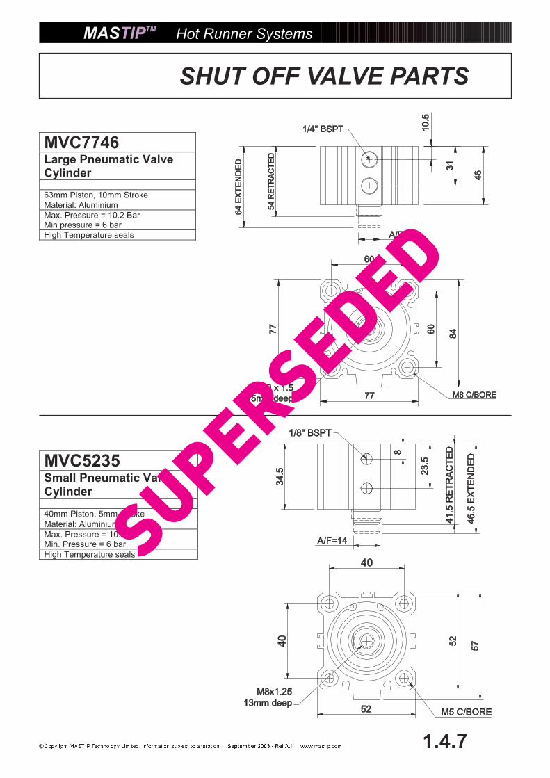
Hot Runner Systems
1.4.7
SHUT OFF VALVE PARTS
1/4" BSPT
46
54
RE
TR
AC
TE
D
64
EX
TE
ND
ED
77
84
77
A/F=17
31
60
60
10.5
M8 C/BOREM10 x 1.5
15mm deep
52
57
52
40
34
.5
41
.5R
ET
RA
CT
ED
46
.5E
XT
EN
DE
D
8
23
.5
40
M5 C/BORE
A/F=14
M8x1.25
13mm deep
1/8" BSPT
MVC7746Large Pneumatic ValveCylinder
63mm Piston, 10mm Stroke
Material: Aluminium
Max. Pressure = 10.2 BarMin pressure = 6 bar
High Temperature seals
MVC5235Small Pneumatic ValveCylinder
40mm Piston, 5mm Stroke
Material: Aluminium
Max. Pressure = 10.2 barMin. Pressure = 6 bar
High Temperature sealsSuperSeded

Hot Runner Systems
1.4.8
SHUT OFF VALVE PARTS
M10X1.5
20 DEEP
49
49C
12
17
8 8
Ø14
A/F12
1/8” BSP
36
36
4 THRU HOLES
M5 C/BORE
B(R
ET
RA
CT
ED
)
A(E
XT
EN
DE
D)
MVC2510 & MVC2505Hydraulic Valve Cylinder
25mm Piston, 10mm & 5mm Stroke
Material: Aluminium
Max. Pressure = 200 bar
A B C STROKE
MVC2505 63 58 50 5
MVC2510 73 63 55 10
SuperSeded