Embed Size (px)
Citation preview
CAD/CAM 3(1-2), AIT-UG (January’ 2018) 1
MT 21_CAD/CAM 3(1-2)
Than Lin, Ph.D. Assistant Professor
Asian Institute of Technology
Lecture: Week_10

CAD/CAM 3(1-2), AIT-UG (January’ 2018) 2
Computer Assisted Part Programming
One alternative to manual part programming is to use high-level programming languages.
These languages are based on common English words and easy-to-use mathematical notations. Programming an NC controller with one of the high-level programming involves use of the following procedure to obtain G-code. ----?
CAD/CAM 3(1-2), AIT-UG (January’ 2018) 3
Computer Assisted Part Programming
Programming an NC controller with one of the high-level programming involves use of the following procedure to obtain G-code. - To identify the part geometry, general cutter motions, feeds, speeds, and cutter parameters. - To code the part geometry, cutter motions, and general machine instructions. This code is called a source. (APT for this purpose will be describe in next section) - The source is compiled to produce the machine-independent list of cutter movements and auxiliary machine control information known as the cutter location data file (CL data file). It is ISO format. - The CL data are processed by a post-processor to generate machine control data for the particular machine.
CAD/CAM 3(1-2), AIT-UG (January’ 2018) 4
Automatically Programmed Tool
It is most comprehensive and widely used part programming language.
– First prototype system APT I was developed at MIT in 1956. – APT II was developed in 1958, sponsored by Aerospace Industries Associa
tion. – APT III came out in 1961. – The capabilities of APT are being continuously expanded; the present APT
language can control machines with as many as five motion axes.
Other automated part programming languages more or less followed APT’s ideas. Some of them are: ADAPT, AUTOSPOT, EXAPT, COMPACT,
SPLIT.
(APT) Pg-20

CAD/CAM 3(1-2), AIT-UG (January’ 2018) 5
A long series of instruction for a computer which specify the path that the tool must follow in order to produce a part
Geometry statements Geometry description is included in the program
Motion statements Specifies the way that the tool should move along geometry
APT Programming

CAD/CAM 3(1-2), AIT-UG (January’ 2018) 6
Point geometry description ■ by coordinates POINT/X coordinate Y coordinate Z coordinate
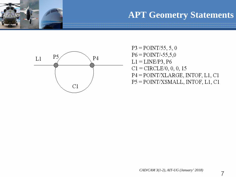
■ by intersection of two lines POINT/INTOF, symbol for a line, symbol for a line
■ by a centre of a circle POINT/CENTER, symbol for a circle
■ by intersection of a line and a circle POINT/D,(Pg-5) INTOF, symbol for a circle, symbol for a line (∆ is one of: Xsmall, Xlarge, Ysmall, Ylarge)
APT Geometry Statements
CAD/CAM 3(1-2), AIT-UG (January’ 2018) 7
APT Geometry Statements

CAD/CAM 3(1-2), AIT-UG (January’ 2018) 8
APT Geometry Statements
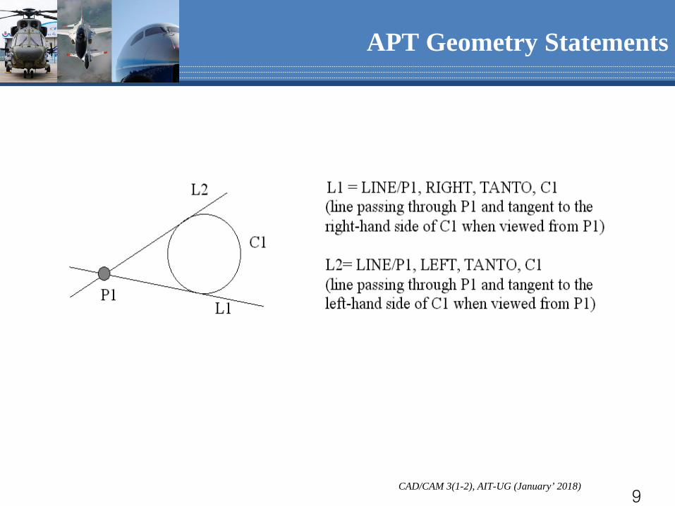
Line geometry description through two points LINE/symbol for a point, symbol for a point by a point and a tangent circle LINE/(Pg-7) symbol for a point, ,TANGTO, symbol for a circle through a point and an angle with another line LINE/symbol for a point, ATANGLE,value,symbol for a line
LEFT
RIGHT
CAD/CAM 3(1-2), AIT-UG (January’ 2018) 9
APT Geometry Statements
CAD/CAM 3(1-2), AIT-UG (January’ 2018) 10
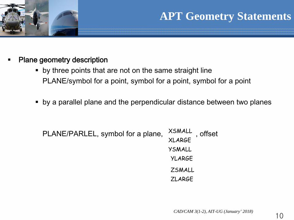
Plane geometry description by three points that are not on the same straight line PLANE/symbol for a point, symbol for a point, symbol for a point by a parallel plane and the perpendicular distance between two planes
PLANE/PARLEL, symbol for a plane, , offset
APT Geometry Statements
XLARGE XSMALL
YLARGE YSMALL
ZLARGE ZSMALL
CAD/CAM 3(1-2), AIT-UG (January’ 2018) 11
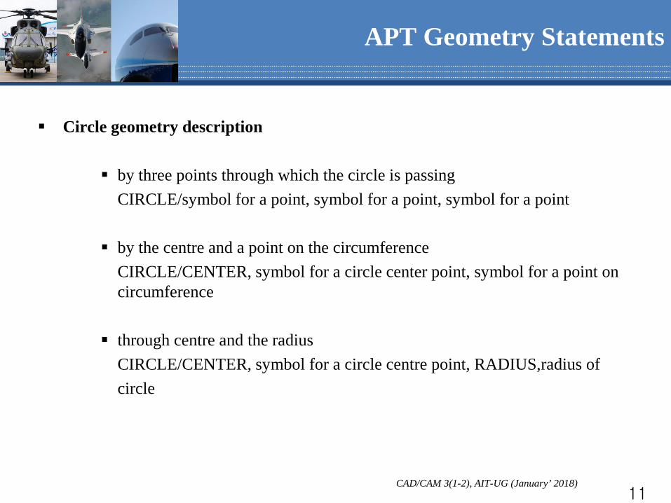
Circle geometry description by three points through which the circle is passing CIRCLE/symbol for a point, symbol for a point, symbol for a point by the centre and a point on the circumference CIRCLE/CENTER, symbol for a circle center point, symbol for a point on
circumference through centre and the radius CIRCLE/CENTER, symbol for a circle centre point, RADIUS,radius of circle
APT Geometry Statements

CAD/CAM 3(1-2), AIT-UG (January’ 2018) 12
APT Control Surfaces
Three controlling surfaces Part surface on which the end of the tool rides, usually a plane Drive surface along which the tool slides, defines the contour to cut Check surface determines the beginning or end of the tool’ motion
Reason for check surface: the tool needs three surfaces to completely determine its position
CAD/CAM 3(1-2), AIT-UG (January’ 2018) 13
Point-to-point motion statement indicates the initial position of the cutter centre FROM/symbol for a defined point positions the tool centre at a specific point GOTO/symbol for a defined point positions the cutter in the specific increment from its current location GODLTA/∆X, ∆Y, ∆Z
APT Motion Statements

CAD/CAM 3(1-2), AIT-UG (January’ 2018) 14
Contour motion statement (position) GO/M1, Drive surface, M2, Part surface, M3, Check surface M1, M2 in {TO, PAST, ON}(Pg-13); M3 in {TO, PAST, ON, TANTO};
they are the specifiers to indicate the desired location of the cutter with respect to the associated control surface. Without them, it is not sufficient.
APT Motion Statements

CAD/CAM 3(1-2), AIT-UG (January’ 2018) 15
- Specifiers for position statements - TO: Tool slides along DS from its current position and stops when it first touches CS ON: Tool slides along DS from its current position and stops when its tip point lies in CS PAST: Tool slides along DS from its current position and stops when it touches CS in the other side of CS
APT Motion Statements
CS
DS
CS
DS
CS
DS
CAD/CAM 3(1-2), AIT-UG (January’ 2018) 16
Contour motion statement (sliding) move left from the previous direction and along the drive surface GOLFT/ move right from the previous direction and along the drive surface GORGT/symbol for a defined point move up along the drive surface (i.e., away from the part surface) GOUP/ move down along the drive surface (i.e., away from the part surface) GODOWN/ move forward from a tangent position along a tangent direction GOFWD/ move backward from a tangent position along a tangent direction GOBACK/
APT Motion Statements

CAD/CAM 3(1-2), AIT-UG (January’ 2018) 17
An Example FROM/SP GO/TO, L1, TO, PS, ON L4 GORGT/L1, PAST, L2 GOLFT/L2, PAST, L3 GOLFT/L3, PAST, C1 GOLFT/C1, PAST, L3 GOLFT/L3, PAST, L4 GOLFT/L4, PAST, L1 GOTO/SP (Part surface PS is assumed to be on the plane z=1)
APT Motion Statements
SP
L1
L2
L3
C1
L3
L4

CAD/CAM 3(1-2), AIT-UG (January’ 2018) 18
Additional APT statements – Postprocessor statement MACHIN/postprocessor name COOLNT/ON SPINDL/ON FEDRAT/feedrate SPINDL/spindle speed, CCLW TOOLNO/tool number, length END
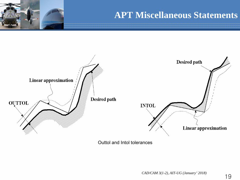
– Tolerance and cutter specification OUTTOL/(Pg-17) outer tolerance INTOL/ (Pg-17) inner tolerance TOLER/outer and inner tolerance CUTTER/cutter size
APT Miscellaneous Statements
CAD/CAM 3(1-2), AIT-UG (January’ 2018) 19
Outtol and Intol tolerances
APT Miscellaneous Statements
CAD/CAM 3(1-2), AIT-UG (January’ 2018) 20
Additional APT statements – Initial and termination statement PARTNO/program name FINI (last statement)
APT Miscellaneous Statements

CAD/CAM 3(1-2), AIT-UG (January’ 2018) 21
APT Programming
Post-processing (drivers)
Part Geometry
APT Programming
Human Help
CLDADA
Driver 1
Driver 2
Driver n
Machine 1
Machine 2
Machine n

CAD/CAM 3(1-2), AIT-UG (January’ 2018) 22
APT Post-processing
CLDATA File – the CLDATA file forms the interface between the general purpose NC processors and their postprocessor – holds the information concerning the computed tool path and the auxiliary instructions for each part program, i.e. information which will be used by the
post processor to produce a G-M coded program – each logical record in the CLDATA file is a separate block of data – the first word of each record is the record sequence number – the second word is the classification code – the third and all subsequent words up to a maximum of 245 words are based on the particular classification code of the record – The task of the post processor program is to convert the CLDATA information
to the exact requirements of the particular machine and control system on which the component will be cut
CAD/CAM 3(1-2), AIT-UG (January’ 2018) 23
APT Post-processing
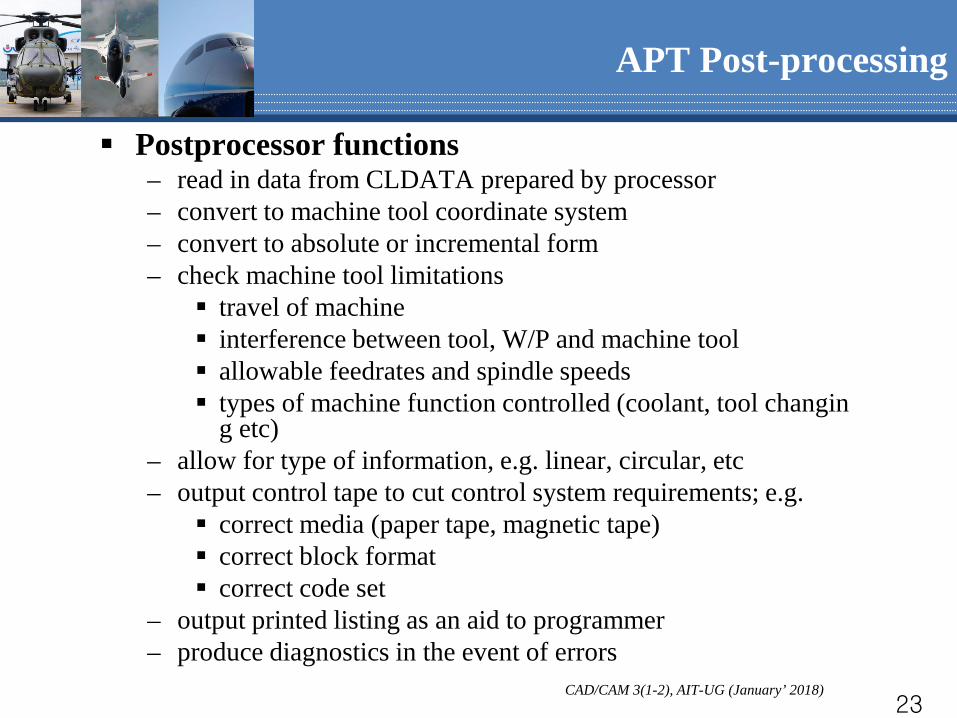
Postprocessor functions – read in data from CLDATA prepared by processor – convert to machine tool coordinate system – convert to absolute or incremental form – check machine tool limitations
travel of machine interference between tool, W/P and machine tool allowable feedrates and spindle speeds types of machine function controlled (coolant, tool changin
g etc) – allow for type of information, e.g. linear, circular, etc – output control tape to cut control system requirements; e.g.
correct media (paper tape, magnetic tape) correct block format correct code set
– output printed listing as an aid to programmer – produce diagnostics in the event of errors
CAD/CAM 3(1-2), AIT-UG (January’ 2018) 24
APT Post-processing
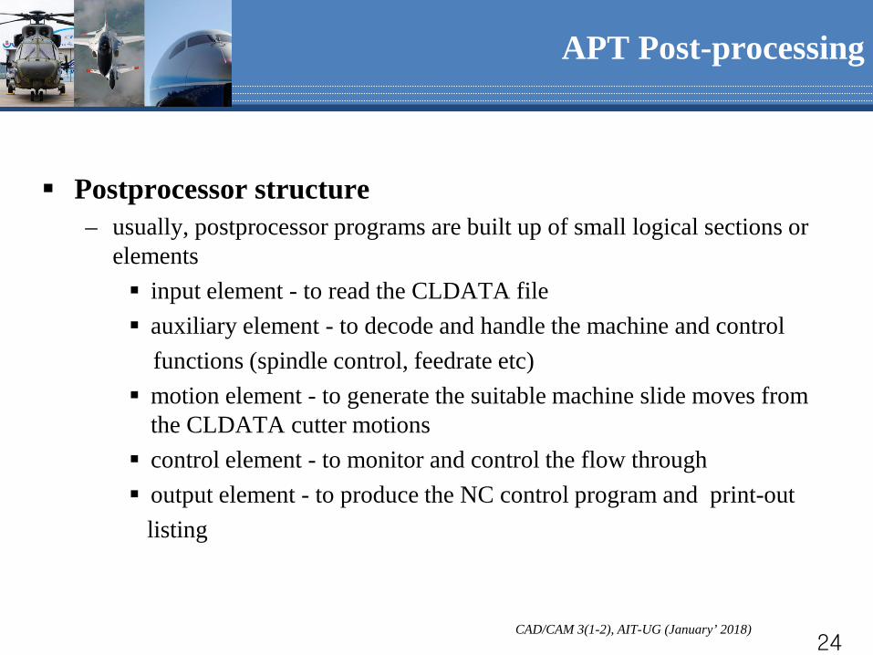
Postprocessor structure – usually, postprocessor programs are built up of small logical sections or
elements input element - to read the CLDATA file auxiliary element - to decode and handle the machine and control functions (spindle control, feedrate etc) motion element - to generate the suitable machine slide moves from
the CLDATA cutter motions control element - to monitor and control the flow through output element - to produce the NC control program and print-out listing

CAD/CAM 3(1-2), AIT-UG (January’ 2018) 25
APT Post-processing
Modular structure of postprocessor
Processor
e.g. APT etc
Control
element
Output
element
Motion
element
Auxiliary
element
Input
element
CAD/CAM 3(1-2), AIT-UG (January’ 2018) 26
APT Programming
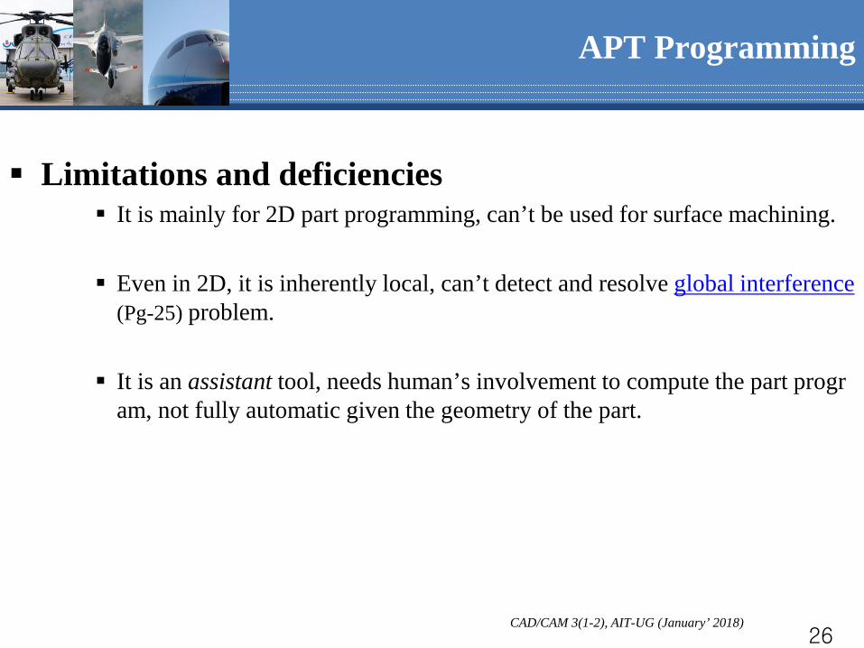
Limitations and deficiencies It is mainly for 2D part programming, can’t be used for surface machining.
Even in 2D, it is inherently local, can’t detect and resolve global interference
(Pg-25) problem.
It is an assistant tool, needs human’s involvement to compute the part program, not fully automatic given the geometry of the part.
CAD/CAM 3(1-2), AIT-UG (January’ 2018) 27
APT Programming
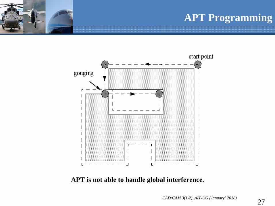
APT is not able to handle global interference.

CAD/CAM 3(1-2), AIT-UG (January’ 2018) 28
The tool axis remains fixed during the entire machining operation. It is widely used in NC machining
– Mature technique, stable and robust tool path generation algorithms. – Relatively inexpensive 3-axis machines.
Two major methods for tool path calculation – Contact point method (seldom, 5-axis only) – Drive-plane/Upper-envelope method (popular)
3-axis Surface Machining
CAD/CAM 3(1-2), AIT-UG (January’ 2018) 29
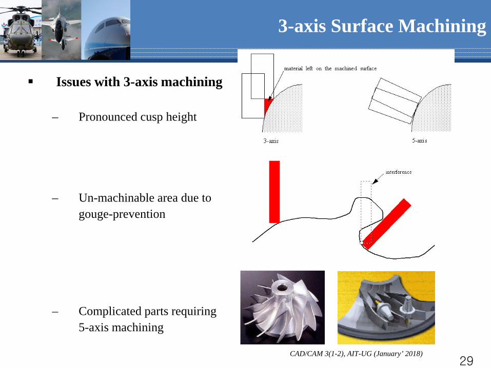
Issues with 3-axis machining
– Pronounced cusp height
– Un-machinable area due to gouge-prevention
– Complicated parts requiring 5-axis machining
3-axis Surface Machining
CAD/CAM 3(1-2), AIT-UG (January’ 2018) 30

CAD/CAM 3(1-2), AIT-UG (January’ 2018) 31

CAD/CAM 3(1-2), AIT-UG (January’ 2018) 32
CAD/CAM 3(1-2), AIT-UG (January’ 2018) 33