Embed Size (px)
Citation preview

AE10800VD2-01
MST-800VD
Serial No. 4001 and up
Unsafe use of this machine may cause serious injury or
death. Operators and maintenance personnel must read
this manual before operating or maintaining this
machine. This manual should be kept near the machine
for reference and periodically reviewed by all personnel
will come into contact with it.


A-1
CONTENTS
ITEM Page
FOREWORD 0- 1
1. Foreword 0- 2
2. Introduction 0- 3
3. Safety information 0- 4
4. Location of serial number 0- 5
SAFETY 1- 1
1. General precautions 1- 2
2. Precautions during inspection and maintenance 1- 4
3. Precautions before starting engine 1- 9
4. Precautions when starting engine 1-11
5. Precautions when traveling 1-12
6. Precautions for operation 1-15
7. Precautions for transportation 1-17
8. Position for attaching safety labels 1-18
OPERATION 2- 1
1. General view 2- 2
1.1 General view of machine 2- 2
1.2 General view of operator’s compartment 2- 4
1.3 General view of control panel box 2- 5
1.4 General view of monitor panel 2- 5
2. Explanation of components 2- 6
2.1 Meters and lamps on control panel box 2- 6
2.2 Meters and lamps on monitor panel 2- 8
2.3 Switches and levers on control panel box 2-11
2.4 Warning devices 2-13
2.5 Travel lever 2-14
2.6 Dump control lever 2-16
2.7 Dump body safety bar 2-16
2.8 Fuse box in control panel box 2-17
2.9 Fuses and fusible link inside wiring harness 2-18
2.10 Operator’ seat Applicable to Cab Specifications 2-19
2.10 Operator’ seat Applicable to Canopy Specifications 2-21
2.11 Seat belt 2-22
2.12 Cab door lock releasing lever Applicable to Cab Specifications 2-23
2.13 Opening and closing cab front door Applicable to Cab Specifications 2-23
2.14 Engine inspection cover 2-24
2.15 Battery inspection cover 2-24
2.16 Front grill 2-24
2.17 Undercover 2-25

A-2
ITEM Page
3. Operation 2-26
3.1 Check before starting engine 2-26
3.2 Operations and checks before starting engine 2-31
3.3 Starting engine 2-32
3.4 Moving machine off 2-35
3.5 Shifting speed range, changing between FORWARD and REVERSE 2-36
3.6 Steering machine 2-38
3.7 Stopping machine 2-40
3.8 Emergency stopping machine 2-40
3.9 Parking machine 2-41
3.10 Stopping engine 2-41
3.11 Checks after stopping engine 2-42
3.12 Locking 2-42
3.13 Precautions when traveling 2-43
4. Handling dump body 2-44
4.1 Dumping operation of dump body 2-44
4.2 Locking dump control lever 2-44
4.3 Operating safety bar 2-45
4.4 Precautions during operation 2-46
5. Manual release parking brake 2-47
5.1 Outline of parking brake 2-47
5.2 Method for manual release of parking brake 2-47
6. Handling rubber crawler 2-49
6.1 Features of rubber crawler 2-49
6.2 Prohibited operations for rubber crawler 2-49
6.3 Precautions when using rubber crawler 2-50
7. Transportation 2-51
7.1 Loading, unloading work 2-51
7.2 Precautions for loading 2-51
7.3 Precautions for transportation 2-51
8. Cold weather operation 2-52
8.1 Precautions for low temperature 2-52
8.2 After completion of work 2-53
8.3 After cold weather 2-53
9. Long-term storage 2-54
9.1 Before storage 2-54
9.2 Precautions during storage 2-54
9.3 Precautions after storage 2-54

A-3
ITEM Page
10. Handling battery 2-55
10.1 Precautions when handling battery 2-55
10.2 Removal and installation of battery 2-56
10.3 Precautions when charging battery 2-56
10.4 Starting engine with booster cable 2-57
11. Troubleshooting 2-58
11.1 Problems with engine related parts 2-58
11.2 Problems with chassis related parts 2-59
11.3 Problems with electric related parts 2-60
MAINTENANCE 3- 1
1. Basic outline of maintenance 3- 2
2. Precautions for maintenance 3- 4
3. Use of fuel and lubricants according to ambient temperature 3- 6
3.1 Fuel, coolant, and lubricant table 3- 6
4. Tools and tightening torques 3-8
4.1 Introduction of necessary tools 3-8
4.2 Torque list for bolts and nuts 3-9
5. Periodic replacement of critical parts 3-10
5.1 Periodic replacement interval (every 2 years) 3-10
5.2 Periodic inspection 3-10
5.3 Specified periodic replacement parts 3-11
6. Maintenance schedule chart 3-12
7. Service procedure 3-13
7.1 Outline of inspection and maintenance procedures 3-13
7.2 Initial 100 hours service 3-13
7.3 Initial 500 hours service 3-13
7.4 When required 3-14
7.5 Check before starting 3-26
7.6 Every 50 hours service 3-31
7.7 Every 250 hours service 3-31
7.8 Every 500 hours service 3-32
7.9 Every 1500 hours service 3-36
SPECIFICATIONS 4- 1
1. Dimension drawing 4- 2
2. Specifications table 4- 3

A-4

0-1
FOREWORD
1. FOREWORD 0- 2
2. INTRODUCTION 0- 3
3. SAFETY INFORMATION 0- 4
4. LOCATION OF SERIAL NUMBER 0- 5

0-2
1. FOREWORD
Thank you for purchasing this Morooka Rubber Crawler Carrier.
This manual describes procedures for operation, handling, testing, and maintenance.
It will help the operator realize many years of faithful service from the machine.
Please read this manual carefully BEFORE operating the machine. This will enable
you to realize the peak performance of the machine.
For details of handling the engine, please see the separate engine operation manual
for any item not given in this manual.
• Improper operation and maintenance of this machine can be hazardous and could result in serious injury or death.
• Operators and maintenance personnel should read this manual thoroughly before beginning operation or maintenance. Always keep this manual on the machine and be sure to read and understand it thoroughly before performing operation and maintenance.
• Some actions involved in operation and maintenance of the machine can cause a serious accident if they are not done in the manner described in this manual.
• Keep this manual handy and have all personnel read it periodically. • If this manual has been lost or has become dirty and cannot be read, request a replacement manual from Morooka or your Morooka distributor.
• If you lend this machine to another person, always have that person read the operation manual and make sure that they understand the content of the manual before starting operation.Be particularly careful to ensure that they follow the safety regulations when operating.
• Continuing improvements in the design of this machine can lead to changes in detail which may not be reflected in this manual. Consult Morooka or your Morooka distributor for the latest available information of your machine or for questions regarding information in this manual.
• The description of safety is given in SAFETY INFORMATION on page 0-3 and in SAFETY from page 1-1.

0-3
2. INTRODUCTION
1. FEATURES OF THE MACHINE
• Low-ground-pressure rubber crawler type that can travel easily on uneven ground, soft ground,
or snow.
• Long, wide rubber crawler to provide powerful and stable drawbar pull .
• Hydraulic drive (HST) to allow travel operations to be carried out with a single lever to give
forward and reverse with stepless gear shifting, as well as turning and stopping.
2. BREAKING IN THE MACHINE
Your Morooka machine has been thoroughly adjusted and tested before shipment.
However, operating the machine under severe conditions at the beginning can adversely affect
the performance and shorten the machine life.
Be sure to break in the machine for the initial 100 hours (as indicated by the hourmeter). Proper
breaking in will allow the machine to give you many years of service.
During breaking in, pay particular attention to the following points.
• After starting the engine, idle it for 5 minutes to carry out the warming -up operation.
• Avoid operation with heavy loads or at high speeds.
• Avoid sudden starts, sudden acceleration, sudden steering and sudden stops except in cases
of emergency.
3. WARRANTY
If any failure that is considered to be the responsibility of Morooka should occur within 6 months
of delivery of the new machine or within 600 hours on the hourmeter, whichever comes sooner,
repairs will be carried out free of charge in accordance with the warranty.

0-4
3. SAFETY INFORMATION
Most accidents are caused by the failure to follow fundamental safety rules for the operation and
maintenance of machines.
To avoid accidents, read, understand and follow all precautions and warnings in this manual and
on the machine before performing operation and maintenance.
Do not operate or carry out maintenance of this machine unless you are sure that yo u
understand the explanations and procedures completely.
To identify safety messages in this manual and on machine labels, the following signal words are
used.
This word is used on safety messages and safety labels where there
is a high probability of serious injury or death if the hazard is not
avoided. These safety messages or labels usually describe
precautions that must be taken to avoid the hazard. Failure to avoid
this hazard may also result in serious damage to the machine.
This word is used on safety messages and safety labels where there
is a potentially dangerous situation which could result in serious
injury or death if the hazard is not avoided. These safety messages
or labels usually describe precautions that must be taken to avoid the
hazard. Failure to avoid this hazard may also result in serious
damage to the machine
This word is used on safety messages and safety labels for hazards which could
result in minor or moderate injury if the hazard is not avoided. This word might also
be word for hazards where the only result could be damage to the machine.
This word is used for precautions that must be taken to avoid actions which could
shorten the life of the machine.
Safety precautions are described in SAFETY from page 1-1.
Morooka cannot predict every circumstance that might involve a potential hazard in operation and maintenance.
Therefore the safety messages in this manual and on the machine may not include all possible safety precautions.
If any procedures or actions not specifically recommended or allowed in this manual are used, it is your
responsibility to be sure that you and others can do such procedures and actions safely and without damaging the
machine. If you are unsure about the safety of some procedures, contact your Morooka distributor.
NOTICE

0-5
4. LOCATION OF SERIAL NUMBER
On this machine, there is plate with the machine serial number
stamped on it stuck to the left side surface of the travel lever stand
inside the operator’s compartment in the position in the diagram on the
right.
For the position of the engine serial number, please see the separate engine operation manual.
When inquiring about service or ordering parts, please quote the machine serial number, engine serial number,
and hour-meter reading.

0-6

1-1
SAFETY
1. General precautions 1- 2
2. Precautions during inspection and maintenance 1- 4
3. Precautions before starting engine 1- 9
4. Precautions when starting engine 1-11
5. Precautions when traveling 1-12
6. Precautions during operation 1-15
7. Precautions for transportation 1-17
8. Position for attaching safety labels 1-18
Read and follow all safety precautions. Failure to do so may result in serious injury or death.
This safety section also contains precautions for optional equipment and attachments.

1-2
1. GENERAL PRECAUTIONS
SAFETY RULES
• Only trained and qualified personnel, or personnel authorized by the company (or superior) can operate and maintain the machine.
• Follow all safety rules, prohibitions, precautions, procedures, and instructions when operating or performing maintenance on the machine, and pay careful attention to safety.
• Operating the machine when you are not in good physical condition reduces the power of judgment needed to avoid danger and leads to accidents. People in the following conditions should not operate the machine. • People who cannot operate normally because they are tired, ill, or suffering from the effects of medication.
• People who have been drinking. • Pregnant women
SAFETY FEATURES
• Be sure that all guards and covers are in their proper position. Have guards and covers repaired if damaged.
• Use safety features such as safety lock levers and seat belts properly. • Improper use of safety features could result in serious bodily injury or death.
Parking brake switch : See “OPERATION 3.7 PARKING MACHINE”. Dump control lever lock : See “OPERATION 4.2 LOOCKING DUMP CONTROL LEVER”. Seat belt : See “OPERATION 2.11 SEAT BELT”.
WEAR SUITABLE CLOTHING
• Always wear properly fitting clothes which allow ease of movement. If there are buttons, always button the cuffs.
• Avoid loose clothing, towels, jewelry, and loose long hair. They can catch on controls or in moving parts and cause serious injury or death.
• Also, do not wear oily clothes, they can easily catch fire. • Wear a hard hat, safety glasses, non-slip safety shoes, and gloves when operating or maintaining the machine.
FIRE EXTINGUISHER AND FIRST AID KIT
• Be sure that fire extinguishers have been provided and read the labels to ensure that you know how to use them.
• Provide a first aid kit at the storage point. • Know what to do in the event of a fire. • Be sure that you know the phone numbers of persons you should contact in case of an emergency.

1-3
UNAUTHORIZED MODIFICATION
• Any modification made without authorization from Morooka can adversely affect the performance of the machine, and may also create hazards.
• Before making a modification, consult your Morooka distributor. Morooka will not be responsible for any injury or damage caused by any unauthorized modification.
FIRE PREVENTION FOR FUEL, OIL, AND ANTIFREEZE
Fuel, oil, and antifreeze can be ignited by a flame. Fuel is particularly flammable and can be hazardous. • Use well-ventilated areas for adding or storing oil and fuel. • Keep oil and fuel in the determined place and do not allow un�authorized persons to enter.
• Tighten all fuel and oil caps securely. • Keep any flame away from flammable fluids. • Do not leave any cloths or rags soaked in oil or fuel lying in the fuel or oil storage area. Clean such materials up immediately.
• Stop the engine and do not bring lighted cigarettes or cigarette lighters close when refueling.
USE HANDRAILS AND STEPS FOR GET ON OR OFF
Get on or off the machine as follows. • Never jump on or off the machine. Never get on or off a moving machine.
• When getting on or off the machine, always face the machine and use the handrails and steps.
• If there is any oil, grease, or mud on the handrails or steps, wipe it off immediately. Always keep these parts clean.

1-4
2. PRECAUTIONS DURING INSPECTION AND MAINTENANCE
NO UNAUTHORIZED PERSONS
Never allow unauthorized persons into the area when carrying out inspection and maintenance. When leaving the operator’s seat to carry out operations, hang a “DO NOT OPERATE ! ” sign (Part No.: 1-41010-1210) on the control lever to prevent any other person from operating the machine.
USE SUITABLE TOOLS
Always use tools that are designed for the purpose. Do not use broken or deteriorated tools, or tools that are designed for other purposes.
STOP ENGINE WHEN INSPECTION AND MAINTENANCE
When carrying out inspection and maintenance, always follow the precautions below. • Select firm, level ground to park the machine. • Lower the dump body, apply the parking brake, then stop the engine.
• Check that the travel lever is at the N position. • If the engine must be started to carry out inspection or maintenance, take steps to ensure that the engine can be stopped at any moment.
• When carrying out the operation with two or more workers, determine the order of operation and fix signals, and follow the instructions of the person in charge.
ALWAYS KEEP MACHINE CLEAN
Always do the following to keep the machine clean. • Always keep the floor, steps, and handrails free of oil, grease, mud, or water. There is danger that you may slip and be injured. Always wipe off any oil, grease, mud or water.
• Do not leave tools or parts lying around on the floor or steps. There is danger that you may trip over them. Always clear up tools and parts immediately.
• Dry wood chips, leaves, grass, paper, oil, and other flammable materials around the engine, muffler, battery, or hydraulic tank may cause fire. Always remove any flammable objects and wipe off any oil.
• Always remove any mud accumulated around the undercarriage. There is danger that you may slip and fall when stepping on to the rubber crawler.
1-5
VENTILATION FOR ENCLOSED AREAS
Exhaust fumes from the engine can kill. • If it is necessary to start the engine within an enclosed area, open the doors and windows to provide adequate ventilation.
KEEP AWAY FROM ROTATING AND MOVING PARTS
• Do not go close to the fan when it is rotating. Do not bring anything that can be caught up in the fan close to the fan.
• Do not come close to the dump body when it is moving. There is danger of getting caught or crushed.
KEEP AWAY FROM FLAME WHEN ADDING FUEL
When filling the fuel tank with fuel, or when draining the water, always follow the precautions below. • Stop the engine. • Do not bring any lighted cigarette or cigarette lighter close to the fuel tank.
• After adding fuel, tighten the cap securely and wipe up any spilled fuel.
• Do not bend the fuel hose or hit it with any sharp object. • If any hose is loose or damaged, always repair or replace it.
1-6
DO NOT TOUCH HIGH-TEMPERATURE, HIGH-PRESSURE PARTS IMMEDIATELY AFTER STOPPING ENGINE
Immediately after stopping the engine, many parts are at high temperature or under high pressure. If parts are removed or touched carelessly, there is danger of burns or other injury. For the following parts particularly, always wait for the machine to cool down before inspecting. • Radiator and radiator cap • Hydraulic tank and hydraulic hoses • Muffler and all parts of engine.
WAIT FOR ENGINE TO COOL BEFORE CHANGING ENGINE OIL
When changing the engine oil, always follow the precautions below. • Stop the engine and wait for the engine and oil temperature to go down before changing the oil.
• After adding oil, tighten the cap and drain valve securely and wipe up any oil that was spilled.
WAIT FOR WATER TEMPERATURE TO GO DOWN BEFORE ADDING COOLANT
Do not add water to the radiator. Always follow the precautions below. • Stop the engine and wait for the water temperature to go down. • Raise the lever attached to the radiator cap to release the internal pressure before removing the cap.
• After adding water, tighten the cap securely and wipe up any water that was spilled.
WAIT FOR PRESSURE TO GO DOWN BEFORE ADDING HYDRAULIC OIL
When adding oil to the hydraulic tank or when changing the oil, always follow the precautions below. • Lower the dump body and stop the engine. • Loosen the hydraulic tank cap slowly to release the internal pressure completely, then remove the cap.
• After adding oil, tighten the cap and drain plug securely and wipe up any oil that was spilled.

1-7
TAKE CARE WHEN HANDLING HIGH PRESSURE HOSES
Remember that oil is always flowing under high pressure in the hydraulic hoses. Do not remove the hoses before the internal pressure has been released. When handling the high-pressure hoses, always follow the precautions below. • Do not bend the high-pressure hoses or hit them with any sharp object.
• If any hose is loose or damaged, repair or replace it. • It is extremely dangerous if oil is leaking from even small holes in the hoses or hydraulic equipment. If such a problem occurs, please contact your Morooka distributor.
BE CAREFUL OF HIGH-PRESSURE GREASE WHEN ADJUSTING RUBBER CRAWLER ATTENTION
The rubber crawler tension adjuster is filled with grease. The grease is kept under high pressure by the recoil spring inside the tension adjuster. Always follow the precautions below when adjusting the tension. If these precautions are not followed, the valve may fly out and cause serious injury. • Do not loosen the tension adjustment valve more than one turn. There is danger that the valve may fly out.
• When adjusting the tension, do not stand directly in front of the valve; stand to the side to avoid danger.
USE SAFETY BAR UNDER DUMP BODY
When going under the dump body to carry out operations, always follow the precautions below. • Hang a "DO NOT OPERATE !" sign (Part No.: 1-41010-1210) in the operator’s compartment to prevent any one else from operating the machine.
• Apply the lock of the dump control lever to prevent the truck box from lowering when the lever is touched inadvertently by an unauthorized person.
Dump control lever lock: See “OPERATION 4.2 LOCKING DUMP CONTROL LEVER OPERATING”.
• Always use the safety bar when going under the dump body. Safety bar: See “OPERATION 4.3 OPERATING SAFETY BAR”.
BE CAREFUL WHEN HANDLING BATTERY
• When checking or repairing the electrical system, always remove the negative (-) terminal from the battery to stop the flow of electricity. Failure to do this may cause fire or short circuit.
• Be careful not to get battery electrolyte on your skin or clothes. If the battery electrolyte gets on you, wash it off immediately with water.
1-8
DO NOT SPRAY WATER ON ELECTRICAL COMPONENTS
When washing the machine, do not spray water on the electrical components. If water gets into the electrical system, it will cause defective operations which may lead to malfunctions. Cover the following parts with a sheet to prevent water from getting on them. • Instrument panel and control panel, switches, sensors, connectors • Starting motor, alternator, sensors, connectors around the engine • Battery, relay, connectors at front right of machine
DISPOSE OF WASTE MATERIAL CORRECTLY
• When draining and changing the oil, always put a container under the engine and tank to catch the oil.
• Do not drain the oil directly into the ground or throw it into rivers or the sewage system.
• When disposing of oil, fuel, coolant, solvent, filters, batteries, and other harmful objects, always use a suitable method or procedure.

1-9
3. PRECAUTIONS BEFORE STARTING ENGINE
ALWAYS CARRY OUT CHECKS BEFORE STARTING
Before starting the engine, always carry out the walk-around checks and inspections given in this manual. • Check the ground under the machine to see if there is any trace of oil or water leakage.
• Be particularly careful to check the undercarriage for loose or missing nuts and bolts.
• If any abnormalities are found during the check, carry out simple repairs. If the repairs are difficult, please contact your Morooka distributor. The machine must not be used before repairs are carried out.
CHECK SAFETY PARTS AND LIGHTING
Check the operation of the following parts and devices needed for operation. • Check that the horn, buzzer, and turn signal lamps work normally. • Check that the front lamps light up normally. • Check that the side mirrors are adjusted so that they give a clear view from the operator’s seat.
• Clean the lights to ensure that they give good visibility. • Adjust the operator’s seat to a suitable position for operation. Always adjust the seat if it has been used by another operator.
• Check that the seat belt can be locked properly. Always adjust if it has been used by another operator.
Cab specifications
Canopy specifications
ALWAYS KEEP OPERATOR’S COMPARTMENT CLEAN
Always do the following to keep the operator’s compartment clean and tidy. • Always keep the floor, steps, and handrails free of oil, grease, mud, or water. There is danger that you may slip and be injured. Always wipe off any oil, grease, mud or water.
• Do not leave tools or parts lying around on the floor or steps. Keep these parts in the proper place to prevent them from obstructing operation.
FIRE PREVENTION
• Completely remove all wood chips, leaves, grass, paper and other flammable materials accumulated in the engine compartment. They could cause a fire.
• Check fuel, lubrication, and hydraulic systems for leaks. Have any leaks repaired. Wipe up any excess oil, fuel or other flammable fluids.

1-10
VENTILATION FOR ENCLOSED AREAS
Exhaust fumes from the engine can kill. • If it is necessary to start the engine within an enclosed area, open the doors and windows to provide adequate ventilation.
SAFETY AT WORKSITE
Before starting operations, thoroughly check the area for any unusual conditions that could be dangerous. • Check the terrain and condition of the ground at the worksite, and determine the best and safest method of operation.
• If there are any dangerous places, erect signs and take other steps to ensure safety.
• Check the depth and flow of water and the ground condition before operating in water or crossing a river. NEVER be in water which is in excess of the permissible water depth.
• If there are bridges or any other structure, check that they are of sufficient strength to support the weight of the machine.
• Inside the jobsite, do not allow any person other than the signalman to come close. Restrict the entry even of related workers.

1-11
4. PRECAUTIONS WHEN STARTING ENGINE
PLACE LEVERS AT NEUTRAL
Always place the levers at the following positions. • Place the travel lever at the N position. • Place the dump control lever at the HOLD position. • Set the parking brake switch to the STOP position.
• Sit properly in the operatorユs seat and fit the seat belt.
Cab specifications
Canopy specifications
CHECK FOR SAFETY IN SURROUNDING AREA
Always check that there are no people in the surrounding area. Be particularly careful to check under the machine. • Never start the engine if a warning tag has been attached to the controls. • When starting the engine, sound the horn to warn people in the area. • Do not allow anyone other than the operator to ride on the machine.

1-12
5. PRECAUTIONS WHEN TRAVELING
CHECK FOR SAFETY IN SURROUNDING AREA
Always check that there are no people in the surrounding area. Be particularly careful to check behind the machine. • If the dump body is raised, always lower it. • Sound the horn to warn people in the area that you are about to start the machine.
AVOID SUDDEN OPERATIONS EXCEPT IN EMERGENCIES
Do not suddenly start, suddenly stop, or suddenly turn the machine or carry out any other operation suddenly. Such operations may cause the crawler to come off and the machine to tip over. • When starting or turning the machine, operate the travel lever slowly. Run the engine at low speed.
• Return the travel lever slowly to the N position. Apply the brake to stop the machine.
• If the travel lever is moved too far beyond the N position to the REVERSE (or FORWARD) position, the engine will run in reverse, or other problems will occur.
• Do not use the parking brake to stop the machine. • If a dangerous state occurs by any possibility, and when it becomes necessary to stop the machine urgently, press the parking brake switch to set it to the STOP position or turn the engine starting switch to the OFF position to stop the engine.
TRAVEL CAREFULLY ON UNEVEN GROUND OR ON CURVES
When traveling on uneven ground or in places where there are many curves, reduce the travel speed and travel carefully. If the machine is traveling at high speed it may turn over or crawler may come off.
NO TRAVELING ON PUBLIC ROADS
This machine is not permitted to travel on public roads. When moving the machine, always transport it by truck or trailer.
BE CAREFUL OF ROAD SHOULDERS
When traveling on narrow agricultural roads, always follow the precautions below. • Do not travel too close to the road shoulder, and travel at reduced speed.
• Do not travel on any soft road shoulder or place covered with grass. • During or after rain, the danger of landslides and falling rocks increases. Always travel at low speed and check that the area is safe.

1-13
AVOID OBSTACLES
Avoid traveling over obstacles or earth embankments as far as possible. If the machine has to travel over an obstacle, do as follows. Never travel over large boulders, breakable objects, pieces of concrete, or other sharp objects. • Reduce the travel speed and travel carefully. • Steer the machine so that the center of the rubber crawler passes directly over the obstacle. Mount the obstacle slowly, and when the machine goes over the top and starts to tip forward, stop the machine. Then slowly start the machine again. Never change direction when doing this.
• Earth embankments may collapse under the weight or vibration of the machine and cause the machine to slip, so drive the machine slowly and do not change speed or direction. Be particularly careful when traveling over freshly dug ditches. They may collapse.
TRAVELING ON SLOPES
When traveling on hills or slopes, always follow the precautions below. •Do not travel at an angle on a hill or slope, or parallel to the slope. Such action could result in the machine tipping over or slipping.
• When traveling up hills or slopes, always travel directly up the slope. Set the travel speed to a low range and keep the travel lever close to the N position (low speed).
• Do not suddenly change speed on the slope. There is danger that the direction of the machine may suddenly change and the machine may slip.
• When traveling down slopes, set the travel speed to a low range, run the engine at low idling, and operate the travel lever to a position less than 1/2 of the full stroke from the N position. If the machine travels too fast, there is danger that the engine will overrun and the machine may slip.
• Do not travel on grass, fallen leaves, wet steel plates, or other slippery objects.
• If a dangerous state occurs by any possibility, and when it becomes necessary to stop the machine urgently, press the parking brake switch to set it to the STOP position or turn the engine starting switch to the OFF position to stop the engine.
ENSURE GOOD VISIBILITY
When working in dark places or at night, turn on the head lamps. Turn on the lights in mist, snow, or rain.

1-14
OPERATE CAREFULLY ON SNOW
• When working on snow or icy roads, even a slight slope may cause the machine to slip to the side, so always travel at low speed and avoid sudden starting, stopping, or turning.
• When there has been heavy snow, the road shoulder and objects placed beside the road are buried in the snow and cannot be seen, so always carry out operations carefully.
PARKING MACHINE
Park the machine on firm, level ground. Select a place where there is no problem of falling rocks, landslides, or floods. If the machine has to be parked on a slope, do as follows. • Stop the machine facing directly up or down the slope. • Always put blocks under the tracks to prevent the machine from moving.
• Lower the dump body fully.
REMOVE KEY WHEN LEAVING MACHINE
When leaving the machine, always do as follows. • Lower the dump body fully. • Apply the parking brake, then stop the engine. • Lock the dump control lever. • Remove the starting key and always take it with you.

1-15
6. PRECAUTIONS FOR OPERATION
USE SIGNALS
When carrying out work with one or more workers, or when using a signalman, determine the signals and the person in charge before starting work, and always follow the agreed procedure. Even when using a signalman, always pay careful attention to the following. • When working in confined spaces or indoors, be careful not to hit the surroundings or the ceiling.
• When operating in urban areas or on roads, put up fences around the jobsite and take steps to ensure the safety of passing traffic and pedestrians.
MAKE JOBSITE FLAT
Make the jobsite flat. This will not only increase the efficiency but will also ensure safety. If the jobsite is dusty, spray water to ensure the visibility.
OPERATE DUMP BODY CAREFULLY
When carrying out dumping operations, be careful of the following. • Check that there is no person or obstacle near the dump body. • Stop the machine at the determined point and operate the dump in accordance with signals from the signalman.
• Block the tracks to prevent the machine from moving in reverse. • When dumping on slopes, there is danger of the machine tipping over. If it is felt that there is danger to the machine, stop the operation immediately.
NO OVERLOADING
Never load the machine above its capacity. Overloading will not only cause failures, but will also cause overrunning and tipping over on slopes.
LOAD DUMP BODY EVENLY
• Do not load the dump body on one side. Always spread the load to maintain the balance in the dump body.
• When carrying long objects, such as timber or steel beams, give careful consideration to the position of the center of gravity of the load, and secure with ropes.
• When stacking U-shaped ditch liners or concrete blocks, lay a plate down first and secure with ropes to prevent the load from slipping.

1-16
DO NOT GO CLOSE TO HIGH-VOLTAGE CABLE
When carrying out operations on jobsites where there are power cables, use a signalman and take steps to protect the electric cables. Check with the electricity company before starting operations. • Going close to high-voltage cables can cause electric shock, even if the machine does not touch the cables. Always maintain the safe distance given below between the machine and the electric cable.
• If the dump body should touch the electric cable, the operator should not leave the operator’s compartment. He should call another worker to report the situation. The following actions are effective in preventing accidents. (1) Wear shoes with rubber soles. (2) Use a signalman to give warning if the machine approaches too
close to the electric cables. • When carrying out operations near high-voltage cables, do not let anyone come close to the machine.
Voltage of
Electrical Cable Minimum Safe
Distance
Low voltage (Distribution line)
100 • 200V 2m
6,600V 2m
Special (Transmission
line)
22,000V 3m
66,000V 4m
154,000V 5m
187,000V 6m
275,000V 7m
500,000V 11m

1-17
7. PRECAUTIONS FOR TRANSPORTATION
USE SAFE RAMPS
Always use ramps which fulfill the following conditions. • Strong ramps which can fully support the weight of the machine. • Ramps with a width greater than the width of the crawlers. • Ramps of a length which will not form a steep angle when placed against the platform of the truck or trailer to be used for transportation. If the ramps are too long and they bend excessively, use blocks to support the ramps as necessary.
• Ramps with hooks and non-slip surface. • Be sure that the ramp surface is clean and free of grease, oil, ice and loose materials. Remove dirt from the machine tracks.
LOADING AND UNLOADING
Loading and unloading the machine always involves potential hazards. EXTREME CAUTION SHOULD BE USED. Always do as follows • Perform loading and unloading on firm level ground only. • Stop the engine of the haulage truck, apply the parking brake securely, then block the tires.
• Set the ramps parallel and in line with the width of the crawlers. • Fix the hooks of the ramps securely to the truck platform. • Set the machine to be loaded in line with the ramps, then approach the ramps at low speed.
• Do not correct the direction of travel when on the ramps. If it is necessary to change the direction, drive the machine off the ramps, and set the machine to the correct direction.
• After loading, put blocks under the front and rear of the crawlers to prevent the machine from moving, then tie the machine down with chains or wire rope.
SHIPPING
• When shipping the machine on a hauling vehicle, obey all state and local laws governing the weight, width, and length of a load. Also obey all applicable traffic regulations.
• Take into account the width, height and weight of the load when determining the shipping route.
1-18
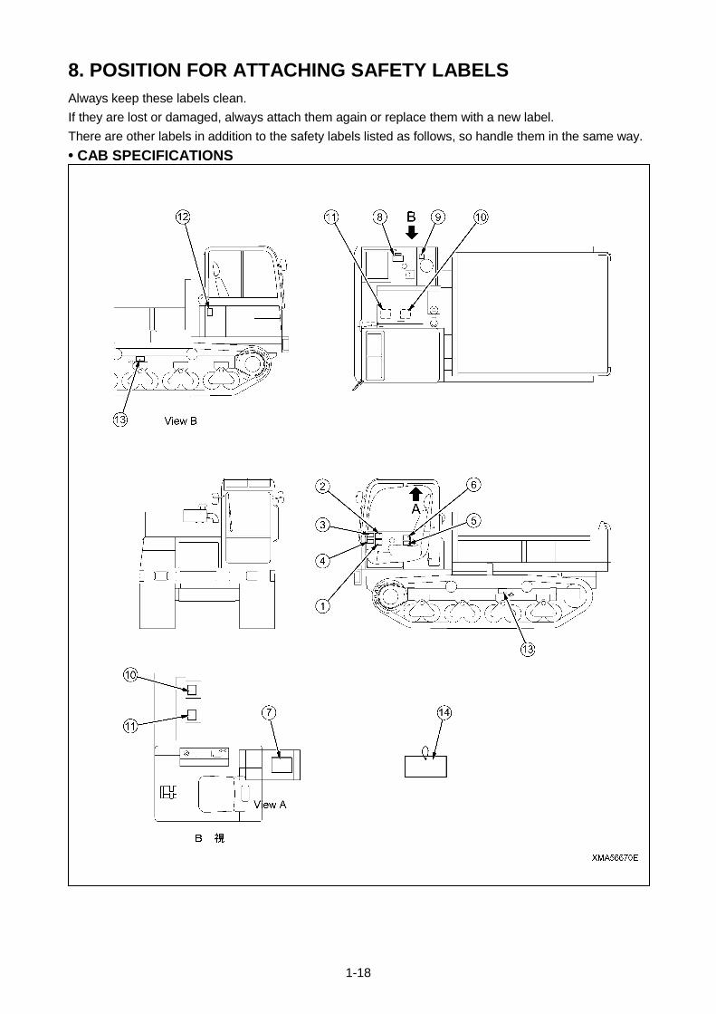
8. POSITION FOR ATTACHING SAFETY LABELS
Always keep these labels clean.
If they are lost or damaged, always attach them again or replace them with a new label.
There are other labels in addition to the safety labels listed as follows, so handle them in the same way.
• CAB SPECIFICATIONS

1-19
8. POSITION FOR ATTACHING SAFETY LABELS
Always keep these labels clean.
If they are lost or damaged, always attach them again or replace them with a new label.
There are other labels in addition to the safety labels listed as follows, so handle them in the same way.
• CANOPY SPECIFICATIONS
1-20
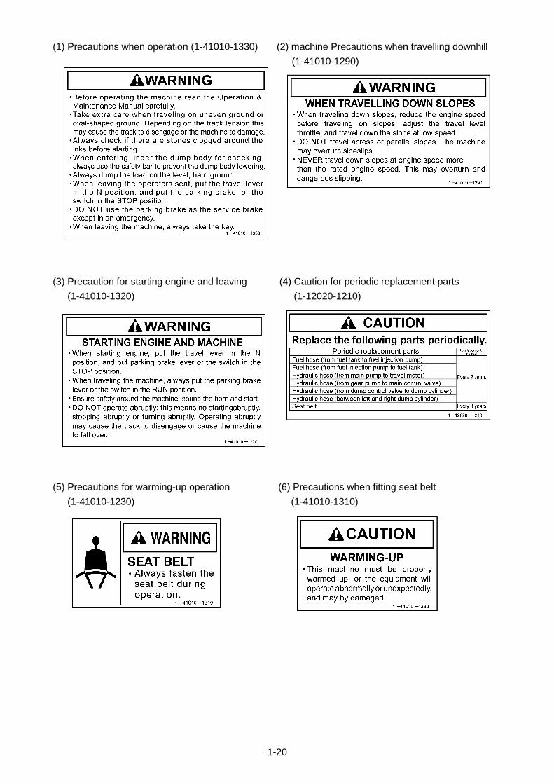
(1) Precautions when operation (1-41010-1330) (2) machine Precautions when travelling downhill
(1-41010-1290)
(3) Precaution for starting engine and leaving (4) Caution for periodic replacement parts
(1-41010-1320) (1-12020-1210)
(5) Precautions for warming-up operation (6) Precautions when fitting seat belt
(1-41010-1230) (1-41010-1310)

1-21
(7) Precautions for slope alarm (1-41010-1360) (8) Precautions when adding fuel (1-41010-1280)
(9) Precautions for oil inside hydraulic tank (10) Beware of rotating fan and pulley
(1-41010-1250) (1-41010-1260)
(11) Beware of high-temperature coolant (12) Beware of rotating crawler (1-41010-1240)
(1-41010-1300)
(13) Precautions for crawler adjustment valve (14) Warning tag to prevent operation during maintenance
(1-41010-1270) (1-41010-1210)

1-22

2-1
OPERATION
1. General view 2- 2
2. Explanation of components 2- 6
3. Operation 2-26
4. Handling dump body 2-44
5. Manual release of parking brake 2-47
6. Handling rubber crawler 2-49
7. Transportation 2-51
8. Cold weather operation 2-52
9. Long-term storage 2-54
10. Handling battery 2-55
11. Troubleshooting 2-58

2-2
1. GENERAL VIEW
1.1 GENERAL VIEW OF MACHINE Cab Specifications
(1) Battery box
(2) Rear view mirror
(3) Fuel tank
(4) Hydraulic tank
(5) Cab
(6) Operator’s seat
(7) Dump body
(8) Safety bar
(9) Rear idler
(10) Carrier roller
(11) Track roller
(12) Dump control lever
(13) Travel motor, sprocket
(14) Rubber crawler
(15) Turn signal lamp
(16) Head lamp
2-3
1. GENERAL VIEW
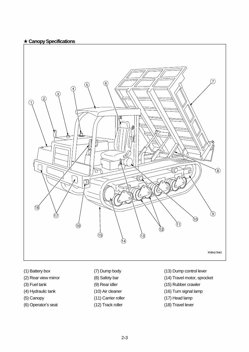
1.1 GENERAL VIEW OF MACHINE Canopy Specifications
(1) Battery box
(2) Rear view mirror
(3) Fuel tank
(4) Hydraulic tank
(5) Canopy
(6) Operator’s seat
(7) Dump body
(8) Safety bar
(9) Rear idler
(10) Air cleaner
(11) Carrier roller
(12) Track roller
(13) Dump control lever
(14) Travel motor, sprocket
(15) Rubber crawler
(16) Turn signal lamp
(17) Head lamp
(18) Travel lever
2-4
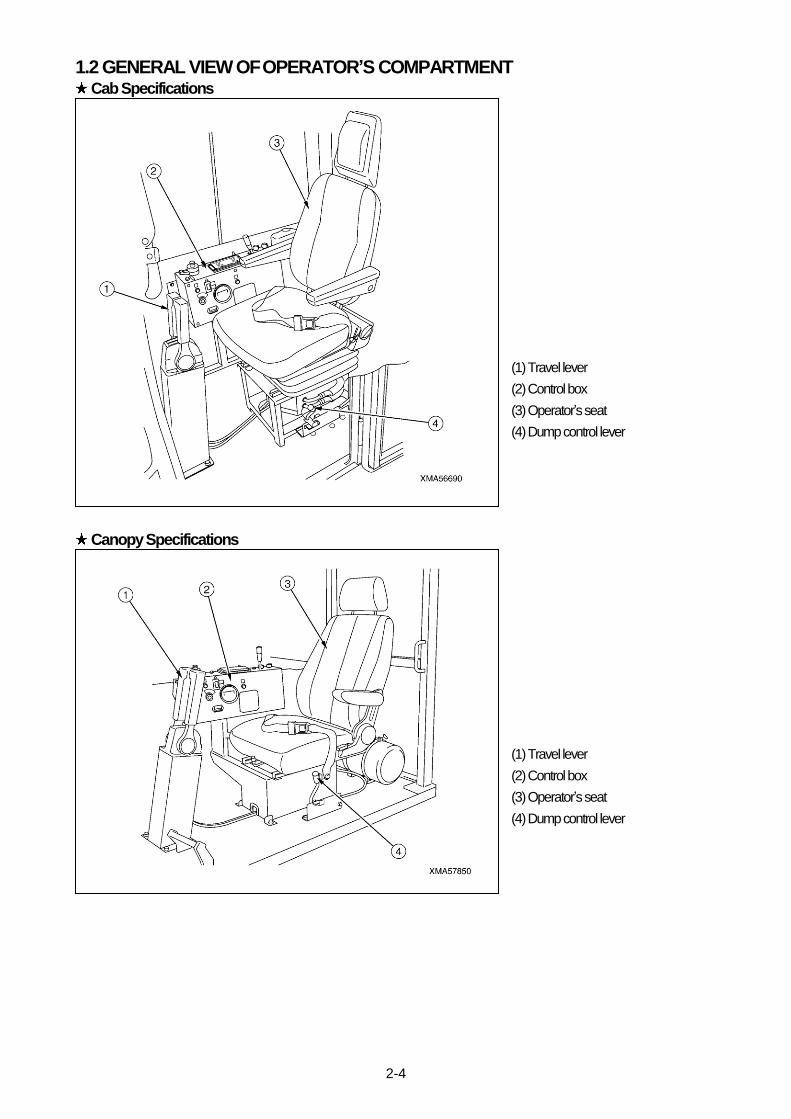
1.2 GENERAL VIEW OF OPERATOR’S COMPARTMENT Cab Specifications
(1) Travel lever
(2) Control box
(3) Operator’s seat
(4) Dump control lever
Canopy Specifications
(1) Travel lever
(2) Control box
(3) Operator’s seat
(4) Dump control lever

2-5
1.3 GENERAL VIEW OF CONTROL PANEL BOX
(1) Turn signal pilot lamp (Right)
(2) Combination switch
(3) Head lamp high beam pilot lamp
(4) Monitor panel
(5) Hi-Lo speed range selector switch
(6) Engine throttle lever
(7) Heater switch
(8) Wiper switch
(9) Fuse box cover
(10) Slope caution lamp
(11) Tachometer
(12) Hourmeter
(13) Parking brake switch
(14) Starter switch
(15) Preheating indicator lamp
(16) Turn signal pilot lamp (Left)
1.4 GENERAL VIEW OF MONITOR PANEL
(1) Engine water temperature gauge
(2) Battery charge lamp
(3) Engine oil pressure caution lamp
(4) HST oil temperature caution lamp
(5) HST oil pressure caution lamp
(6) Fuel gauge
(7) Over-run danger lamp
(8) Over-run caution lamp
(9) Parking brake pilot lamp
(10) High speed travel pilot lamp

2-6
2. EXPLANATION OF COMPONENTS
The following is an explanation of devices needed for operating the machine.
To carry out suitable operations correctly and safely, it is important to understand fully the methods of operating the equipment
and the meanings of the displays.
2.1 METERS AND LAMPS ON CONTROL PANEL BOX [1] TACHOMETR
When traveling uphill or downhill, be sure to regularly check the tachometer to ensure the engine is running at an appropriate speed. In particular, when traveling downhill, run the machine at a slow speed as much as possible to prevent an overrun.
This shows the engine speed.
Immediately after the engine started, the tachometer indication is unstable
for a few seconds, but after that, it should show the correct value.
[2] HOURMETER
This shows the total number of hours of the operation of the machine.
When the starting switch is at the ON position, the meter will advance even if
the machine is not moving.
Use the hourmeter reading as the standard for periodic inspection and
maintenance.
When you stop the engine, always turn the starting switch to the OFF
position.
[3] SLOPE CAUTION LAMP
If this lamp lights up when traveling downhill, the machine has exceeded the permissible range of the slope angle. To prevent the danger of overrun, carry out the following operations quickly and continue to travel downhill. 1. Return the travel lever to the N position and set the travel speed to a range where it does not naturally increase. 2. Operate the engine throttle lever to reduce the engine speed. 3. If the OVERRUN CARE lamp on the monitor panel lights up even when the above operation is carried out, it
means that the machine is exceeding the safe travel speed. Stop the machine immediately and reduce the load on the dump body.
This lamp warns the operator that the machine has entered the danger zone
for the angle of the slope.
If the machine exceeds the permissible slope angle (9 deg) when traveling, the
slope alarm buzzer under the operator’s seat will sound for 5 seconds and the
monitor lamp will light up.

2-7
[4] PREHEATING INDICATOR LAMP
This informs the operator of the actuation condition of the preheating.
When the starting switch is turned to HEAT, it lights up and then goes out to
inform the operator that the preheating of the engine is completed.
Use the HEAT position of the starting switch when starting in cold weather
on when it is difficult to start the engine.
[5] TURN SIGNAL PILOT LAMP
This shows the operation of the turn signal switch in the combination switch.
When the turn signal switch is turned to LEFT side, the left side turn signal
lamp and pilot lamp flashes.
When the turn signal switch is turned to RIGHT side, the right side turn signal
lamp and pilot lamp flashes.
[6] HEAD LAMP HIGH BEAM PILOT LAMP
This shows the operation of the light switch in the combination switch.
When the light switch is turned to HI BEAM, the high beam pilot lamp lights up.
[7] ROOM LAMP (WITH SWITCH) Applicable to Cab Specifications
This room lamp is installed to left side of the cab.
Operate the room lamp switch (1) as follows.
• OFF: Room lamp goes out.
• DOOR: Room lamp lights up when open the door.
• ON: Room lamp lights up.

2-8
2.2 METERS AND LAMPS ON MONITOR PANEL [1] ENGINE WATER TEMPERATURE GAUGE
This indicates the temperature of the engine cooling water.
During operation, the indicator point s should be in the green range.
If the indicator point s is red range, run the engine at low speed and wait for the
indicator point s to go down to the green range.
★After stopping the engine, check for leakage of water from the radiator, and
clogging of the radiator core.
Check also that the fan belt tension and check damage to the fan belt.
[2] FUEL GAUGE
This indicates the amount of fuel remaining in the fuel tank.
When the starting switch is at the ON position, if the indicator points to the E,
there is little fuel remaining, so fill the tank.
Make it a rule to fill the tank (to the point where the indicator points to F when
completing the work at the end of each day.
[3] PARKING BRAKE LAMP
This shows the operation of the parking brake.
If the parking brake switch is set to the ON (STOP) position when the engine is
running, the lamp lights up.
If the parking brake switch is set to the OFF (RUN) position when the engine is
running, the lamp goes out.
[4] HIGH-SPEED TRAVEL PILOT LAMP
This lights up to inform the operator that the machine is in the high speed travel
range.
When the Hi-Lo speed range selector switch is set to the HIGH SPEED, the
lamp lights up.
When the Hi-Lo speed range selector switch is set to the LOW SPEED, the
lamp goes out.
[5] BATTERY CHARGE LAMP
This shows the condition of the charging system.
It lights up when the starting switch is turned ON, and when the engine is
started and the speed rises, it should go out.
If it lights up during operations, there is an abnormality in the charging system.
Stop the engine immediately and check for the problem.
Check the alternator and fan belt tension.
If the inspection shows that there is no abnormality, please contact your
distributor.
2-9
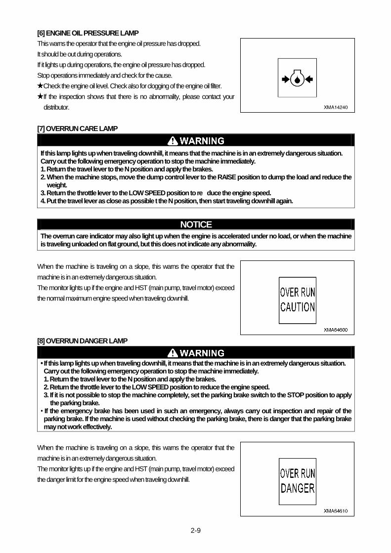
[6] ENGINE OIL PRESSURE LAMP
This warns the operator that the engine oil pressure has dropped.
It should be out during operations.
If it lights up during operations, the engine oil pressure has dropped.
Stop operations immediately and check for the cause.
Check the engine oil level. Check also for clogging of the engine oil filter.
If the inspection shows that there is no abnormality, please contact your
distributor.
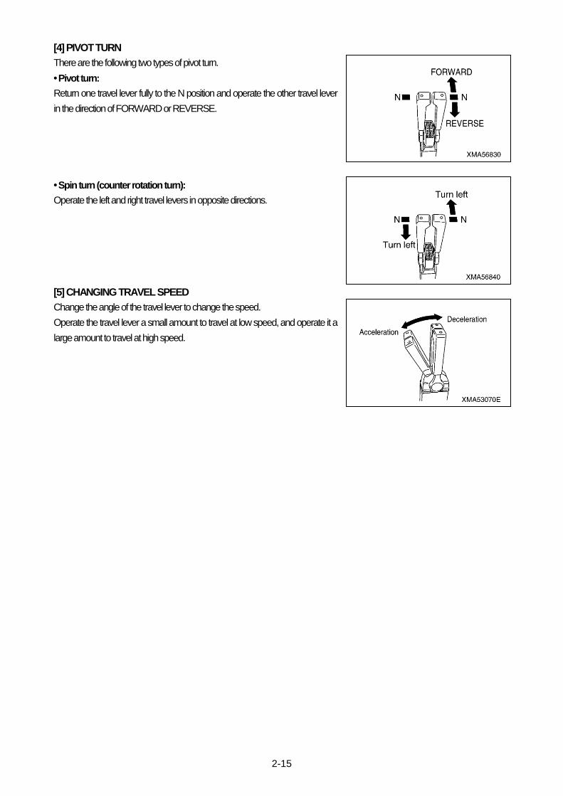
[7] OVERRUN CARE LAMP
If this lamp lights up when traveling downhill, it means that the machine is in an extremely dangerous situation. Carry out the following emergency operation to stop the machine immediately. 1. Return the travel lever to the N position and apply the brakes. 2. When the machine stops, move the dump control lever to the RAISE position to dump the load and reduce the
weight. 3. Return the throttle lever to the LOW SPEED position to re�duce the engine speed. 4. Put the travel lever as close as possible t the N position, then start traveling downhill again.
NOTICE The overrun care indicator may also light up when the engine is accelerated under no load, or when the machine is traveling unloaded on flat ground, but this does not indicate any abnormality.
When the machine is traveling on a slope, this warns the operator that the
machine is in an extremely dangerous situation.
The monitor lights up if the engine and HST (main pump, travel motor) exceed
the normal maximum engine speed when traveling downhill.
[8] OVERRUN DANGER LAMP
• If this lamp lights up when traveling downhill, it means that the machine is in an extremely dangerous situation. Carry out the following emergency operation to stop the machine immediately. 1. Return the travel lever to the N position and apply the brakes. 2. Return the throttle lever to the LOW SPEED position to reduce the engine speed. 3. If it is not possible to stop the machine completely, set the parking brake switch to the STOP position to apply
the parking brake. • If the emergency brake has been used in such an emergency, always carry out inspection and repair of the parking brake. If the machine is used without checking the parking brake, there is danger that the parking brake may not work effectively.
When the machine is traveling on a slope, this warns the operator that the
machine is in an extremely dangerous situation.
The monitor lights up if the engine and HST (main pump, travel motor) exceed
the danger limit for the engine speed when traveling downhill.

2-10
[9] HST OIL PRESSURE LAMP
This warns the operator that the HST oil pressure has dropped.
It should be out during operations.
If it lights up during operations, the HST oil pressure has dropped.
Stop operations immediately and check for the cause.
Check the line filter and strainer for clogging, check for oil leakage from the
hydraulic piping, and check the oil level in the hydraulic tank.
If the inspection shows that there is no abnormality, please contact your
distributor.
[10] HST OIL TEMPERATURE LAMP
This warns of an abnormality in the HST hydraulic oil temperature.
This lamp should be out during operations.
If it lights up during operations, the HST hydraulic oil temperature has dropped
below 20℃ or has risen to approx. 95℃.
If the HST hydraulic oil temperature is below 20℃, carry out the warming-up
operation until the monitor goes out.
If the HST hydraulic oil temperature has gone above 95℃, take steps to
reduce the load on the machine, such as reducing the payload, reducing the
engine speed, and avoiding continuous operation under load.

2-11
2.3 SWITCHES AND LEVERS ON CONTROL PANEL BOX [1] STARTING SWITCH
This switch is used to start and stop the engine.
• OFF: The starting key can be inserted and removed at this position. When
the key is turned to this position, all the switches for the electric circuits are
turned off, and the engine stops.
• ON : Electricity flows to the charging circuit and lamp circuit.
• START: This is the position for starting the engine (the starting motor turns).
When the engine starts, release the key.
The key will return automatically to the ON position.
• PREHEAT: When starting the engine in low temperatures, set the key to this position. The engine intake air is heated to make
it easier to start the engine.
When the preheating indicator lamp (glow indicator) lights up and the preheating is completed, turn the starting key quickly to
the START position to start the engine.
After the engine is started, do not turn the key to the OFF position except when stopping the engine.
[2] ENGINE THROTTLE LEVER
NOTICE • If the engine is stopped before it has cooled down properly, there is danger that the service life of the engine parts will be reduced. Never stop the engine suddenly except in cases of emergency.
• If the engine has overheated, do not suddenly stop it. Run the engine at a midrange speed and gradually cool it down before stopping it.
This lever is used to control the engine speed and output.
• Pulled back: Engine runs at high speed
• Pushed forward: Engine runs at low speed
[3] HI-LO SPEED RANGE SELECTOR SWITCH
• When traveling on slopes, always set the travel speed range to low speed. If the machine is driven in the high speed range, it will cause the engine to overrun.
• When traveling with a load, always set the travel speed range to low speed. If the machine is driven in the high speed range, it will cause the engine to overheat.
This switch is used to select the travel speed range.
When the switch is operated, the speed selection mechanism inside the travel
motor is actuated and the machine enters the high speed range or low speed
range.
In the high speed range and low speed range, if the engine speed and the
amount the travel lever is operated are the same, the travel speed changes.
• HIGH: The travel motor changes to the high speed range and the high speed
lamp on the instrument panel lights up.
• LOW: The travel motor changes to the low speed range and the high speed

2-12
[4] PARKING BRAKE SWITCH
NOTICE
Before starting the engine, always press the parking brake switch to set it to the STOP (parking) position. If it is not in this position, the engine cannot be started.
This switch is used to operate the parking brake inside the travel motor.
• ON (STOP): The parking brake is applied, the parking brake lamp lights up,
and the alarm buzzer sounds.
• OFF (RUN): The parking brake is released and the parking brake lamp goes
out.
[5] COMBINATION SWITCH
This switch is used to operate the horn, head lamps, lighting, and turn signal
lamps.
• Press center of switch: Horn sounds.
• Turn switch knob one stage clockwise: Head lamp (Lo) and instrument
lighting light up.
• Turn switch knob two stages clockwise: Head lamp (Hi) and instrument
lighting light up.
• Move lever back: Left turn signal lamp and turn signal pilot lamp on control
panel box flashes.
• Move lever forward: Right turn signal lamp and turn signal pilot lamp on
control panel box flashes.
[6] HEATER SWITCH Applicable to Cab Specifications
If the heating is used continuously for a long time, the quality of the air inside the operator’s compartment will deteriorate, so open the windows from time to let in fresh air.
This switch is used to operate the heater.
The switch can be pulled up in two stages to select the heating.
• OFF: Heater is stopped.
• Pull out one stage: Heater is actuated and air blows out at low volume.
• Pull out two stage: Heater is actuated and air blows out at high volume.
[7] WIPER, WASHER SWITCH Applicable to Cab Specifications
This switch is used to operate the wiper of the front window.
• Pull out: The wiper moves continuously.
• Push in: The wiper stops.

2-13
2.4 WARNING DEVICES [1] HORN
Horn (1) is installed inside the front grill to the frame on the left side of the
radiator.
When the starting switch is turned ON and the horn switch is pressed, horn (1)
will sound continuously.
Always sound the horn to warn the people in the surrounding area before
starting the engine or before moving the machine off.
[2] SLOPE ALARM BUZZER
Slope alarm buzzer (2) is installed under the operator’s seat.
If the angle of the slope goes above the set angle when the machine is
traveling, slope alarm buzzer (2) will automatically sound intermittently to warn
the operator that the angle is too large.
It is dangerous to continue traveling with the dump body loaded when slope
alarm buzzer (2) sounds.
When traveling downhill, do as follows to prevent any danger from
overrunning.
1. Operate the throttle lever to set the engine speed to low speed.
2. Set the travel lever as close as possible to the N position, then drive the
machine carefully.
3. If the load in the dump body exceeds the maximum payload or is near the
maximum payload, reduce the load.
[3] BACKUP BUZZER
Backup buzzer (3) is installed on the left side inside the frame at the rear of the chassis.
When the engine is started and the travel lever is operated to REVERSE, backup buzzer e will sound intermittently to warn the
operator that the travel lever is at the REVERSE position.
[4] PARKING BRAKE BUZZER
Parking brake buzzer (4) is installed inside the control box in the operator’s compartment.
When the starting switch is turned to ON position and the parking brake switch is operated to the ON (STOP) position, parking
brake buzzer (4) will sound intermittently to inform the operator that the parking brake is applied.
Applicable to Cab Specifications
Applicable to Canopy Specifications

2-14
2.5 TRAVEL LEVER
• Always stop the machine before switching the travel levers between FORWARD and REVERSE. If the direction of travel is suddenly changed, it may cause damage to the machine.
• Do not operate the travel levers by a large amount suddenly. Always operate them slowly. If they are suddenly operated, the machine and the operate will suffer a large shock.
• When stopping the machine, do not return the travel lever past the N (neutral) position. If the lever is moved past the N (neutral) position, it will cause failure such as reverse rotation of the engine.
• Do not make unnecessary counter rotation turns or sudden turns at high speed. There is danger that the crawlers and hydraulic equipment may be damaged, or that the machine may hit some other object.
The travel levers are used to drive the machine in forward or reverse, to stop or steer the machine, and to control the travel
speed.
The travel levers become heavier as they are operated in the direction of FORWARD or REVERSE, and become lighter as
they are operated back towards N (neutral).
[1] TRAVELING STRAIGHT OR STOPPING
Operate the left and right travel levers at the same time.
• FORWARD: Push the levers forward.
• REVERSE: Pull the levers back.
• STOP: Return the levers to the N position.
[2] TURNING (STEERING)
Operate the left and right travel levers at the same time, but operate one lever
more than the other.
• Traveling forward and turning left: Push the right travel lever forward and
return the left travel lever in the direction of N.
• Traveling forward and turning right: Push the left travel lever forward and
return the right travel lever in the direction of N.
• Traveling in reverse and turning left: Pull the right travel lever back and return
the left travel lever in the direction of N.
• Traveling in reverse and turning right: Pull the left travel lever back and return
the right travel lever in the direction of N.
[3] TURNING GRADUALLY
Operate the left and right travel levers by a different amount.
It there is a big difference between the two levers, the machine will turn rapidly.
It there is a small difference between the two levers, the machine will turn
gradually.
2-15
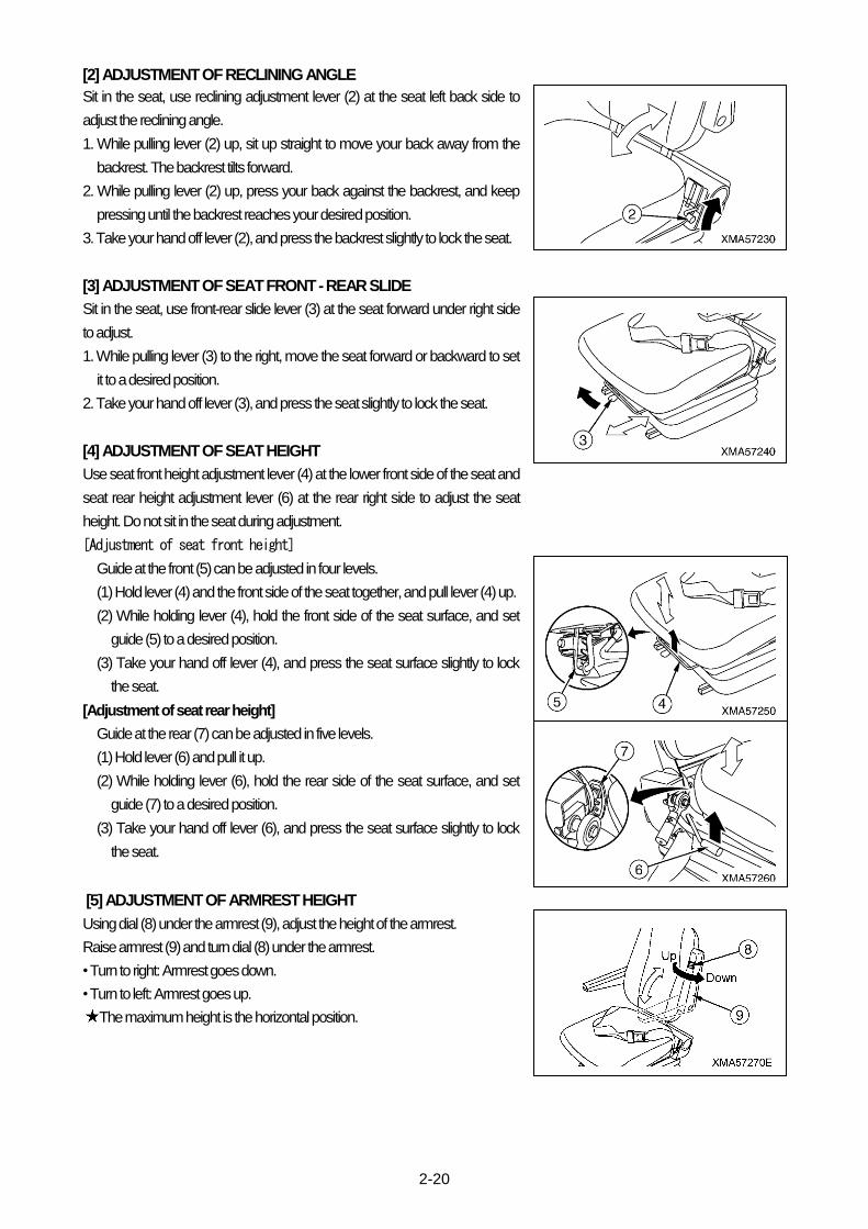
[4] PIVOT TURN
There are the following two types of pivot turn.
• Pivot turn:
Return one travel lever fully to the N position and operate the other travel lever
in the direction of FORWARD or REVERSE.
• Spin turn (counter rotation turn):
Operate the left and right travel levers in opposite directions.
[5] CHANGING TRAVEL SPEED
Change the angle of the travel lever to change the speed.
Operate the travel lever a small amount to travel at low speed, and operate it a
large amount to travel at high speed.

2-16
2.6 DUMP CONTROL LEVER
• Always stop the machine before operating the dump body to the dump position. • Position a signalman to ensure safety in the surrounding area, and follow his signals when carrying out the dumping operation.
• Always operate the dump control lever slowly. If the dump body is suddenly stopped or it is allowed to hit the frame when it is lowered, it will cause failures and will also cause problems of safety in the surrounding area.
• When leaving the operator’s compartment with the dump body raised, always lock the dump control lever. In addition, use the safety bar to prevent the dump body from coming down. Even when the engine is stopped, it is possible to lower the dump body.
[1] DUMP CONTROL LEVER
Dump control lever (1) is used to raise and lower the dump body.
There are three operating positions: RAISE, HOLD, and LOWER.
• RAISE: The dump body is raised.
• HOLD: The dump body is stopped and held in position.
• LOWER: The dump body is lowered.
When the control lever is released, it automatically returns to the HOLD
position.
[2] DUMP CONTROL LEVER LOCK
Lever lock (2) is used to hold the dump control lever at the HOLD position.
2.7 DUMP BODY SAFETY BAR
• If it is necessary to go under the dump body to carry out inspection and maintenance, always use the safety bar to prevent the dump body from coming down.
• When using the safety bar, check that the bar is fitted securely to the dump body holder. • The safety bar is a safety device used during inspection and maintenance. Do not use the safety bar to support the dump body when replacing the dump cylinder, valve, hydraulic hoses, or other equipment. In such cases always support the dump body with a crane.
Safety bar (1) is a device to ensure safety during operations, and is used when
going under the dump body to carry out inspection and maintenance.

2-17
2.8 FUSE BOX IN CONTROL PANEL BOX
• Always turn the starting switch to the OFF position before replacing the fuse. • If the fuse is blown, always check for the cause in that circuit and carry out repairs before replacing the fuse. • When replacing the fuse, always replace it with a fuse of the same capacity.
NOTICE
Fuses are devices to prevent electrical equipment and wiring from burning out. If a fuse is corroded or covered in white powder, always replace it.
1. Remove 4 bolts (1) under side of the control panel box, and remove
inspection cover (2).
2. Remove fuse box cover (3), and check or replace the fuses inside it.
3. The fuses inside the fuse box are for the circuits shown in the table below.
No. Capacity Name of circuit
1 3A Hourmeter, monitor lamps
2 15A
3 15A Combination switch, flasher relay, head right relay, horn relay
4 10A Wiper switch
5 10A Cab power source
6 15A Parking brake switch, parking brake buzzer, Safety relay
7 10A
8 10A Tachometer, High-low speed range selector switch, Backup buzzer, Slope warning unit, HST oil temperature alarm
9 10A Spare (2 pices)
10 15A Spare

2-18
2.9 FUSES AND FUSIBLE LINK INSIDE WIRING HARNESS
• Always turn the starting switch to the OFF position before replacing the fuse.
• If the fuse has melted, always check the circuit to find the cause, and carry out repairs before replacing the fuse.
• When replacing the fuse, always replace it with a fuse of the same capacity.
[1] SIGNS OF FAILURE
If these fuses and fusible links show any of the following signs, carry out inspection and replacement.
• Main fusible link (1)
If the power does not come on when the starting switch is turned to the ON
position, carry out inspection and replacement.
• Slow blow fuse (2) (50A)
If the battery charge lamp stays lighted up during operations, carry out
inspection and replacement.
• Fuse (3) (20A), Fuse (4) (5A)
If the engine does not start even when the starting switch is turned to the
START position, carry out inspection and replacement.
When this is done, the engine will not start if the parking brake switch is at the OFF (RUN) position. Always turn the parking
brake switch to the ON (STOP) position before carrying out operations.
[2] METHOD OF REPLACEMENT
Replace these fuses and fusible links as follows.
1. Open the battery inspection cover. For details, see 2.15 BATTERY INSPECTION COVER in the operation section.
2. Open the rubber cover inside the battery box and check each fuse or fusible link in the wiring harness.
• For main fusible link (1), disconnect the orange connector and carry out inspection and replacement of the red link.
• For slow blow fuse (2), disconnect the orange fuse case connector, take out the fuse, and carry out inspection and
replacement.
• Fuses (3) and (4), open the black cover, take out the fuse, then carry out inspection and replacement.

2-19
2.10 OPERATOR’S SEAT Applicable to Cab Specifications
• Adjust the operator’s seat before operations. Always adjust the operator’s seat after it has been used by another operator.
• Adjust the operator’s seat so that you can operate the travel lever easily with your back against the seat backrest. • Never adjust the seat when traveling. • Always lower the armrest before starting operation. The armrest is installed to prevent the danger of the operator falling from the operator’s seat if the machine tips at an angle when traveling.
(1) Suspension adjustment lever
(2) Reclining adjustment lever
(3) Front-rear slide lever
(4) Seat front height adjustment lever
(6) Seat rear height adjustment lever
(8) Arm rest height adjustment dial
(9) Arm rest
[1] ADJUSTMENT OF SEAT SUSPENSION (hardness)
Sit in the seat, use suspension adjustment lever (1) at the seat right back side
to adjust the suspension.
1. Sit in the seat, make sure that indicator (A) (in red) at the left side of the seat
aligns with red line (B) on the frame.
That indicator (A) aligns with red line (B) brings the most comfortable
hardness of the seat.
The position of indicator (A) changes according to the weight of an
operator on the seat. A lighter weight can move the indicator below red
line (B), and a heavier weight can move it above red line (B).
2. Sit in the seat, and if indicator (A) does not aligns with red line (B), use lever
(1) to adjust the suspension.
(1) Stretch and rotate the grip of lever (1) to select mark "+" or "-" in black.
"+": Select this if indicator (A) is below red line (B). The seat becomes
harder.
"-": Select this if indicator (A) is above red line (B). The seat becomes
softer.
(2) Hold the grip of lever (1) to move it up and down while looking at indicator
(A), and keep moving it until gauge (A) aligns with red line (B).
2-20
[2] ADJUSTMENT OF RECLINING ANGLE
Sit in the seat, use reclining adjustment lever (2) at the seat left back side to
adjust the reclining angle.
1. While pulling lever (2) up, sit up straight to move your back away from the
backrest. The backrest tilts forward.
2. While pulling lever (2) up, press your back against the backrest, and keep
pressing until the backrest reaches your desired position.
3. Take your hand off lever (2), and press the backrest slightly to lock the seat.
[3] ADJUSTMENT OF SEAT FRONT - REAR SLIDE
Sit in the seat, use front-rear slide lever (3) at the seat forward under right side
to adjust.
1. While pulling lever (3) to the right, move the seat forward or backward to set
it to a desired position.
2. Take your hand off lever (3), and press the seat slightly to lock the seat.
[4] ADJUSTMENT OF SEAT HEIGHT
Use seat front height adjustment lever (4) at the lower front side of the seat and
seat rear height adjustment lever (6) at the rear right side to adjust the seat
height. Do not sit in the seat during adjustment.
[Adjustment of seat front height]
Guide at the front (5) can be adjusted in four levels.
(1) Hold lever (4) and the front side of the seat together, and pull lever (4) up.
(2) While holding lever (4), hold the front side of the seat surface, and set
guide (5) to a desired position.
(3) Take your hand off lever (4), and press the seat surface slightly to lock
the seat.
[Adjustment of seat rear height]
Guide at the rear (7) can be adjusted in five levels.
(1) Hold lever (6) and pull it up.
(2) While holding lever (6), hold the rear side of the seat surface, and set
guide (7) to a desired position.
(3) Take your hand off lever (6), and press the seat surface slightly to lock
the seat.
[5] ADJUSTMENT OF ARMREST HEIGHT
Using dial (8) under the armrest (9), adjust the height of the armrest.
Raise armrest (9) and turn dial (8) under the armrest.
• Turn to right: Armrest goes down.
• Turn to left: Armrest goes up.
The maximum height is the horizontal position.

2-21
2.10 OPERATOR’S SEAT Applicable to Canopy Specifications
• Adjust the operator’s seat before operations. Always adjust the operator’s seat after it has been used by another operator.
• Adjust the operator’s seat so that you can operate the travel lever easily with your back against the seat backrest.
• Never adjust the seat when traveling. • Always lower the armrest before starting operation. The armrest is installed to prevent the danger of the operator falling from the operator’s seat if the machine tips at an angle when traveling.
[1] ADJUSTMENT OF SEAT FRONT - REAR SLIDE
Sit in the seat, use front-rear slide lever (1) at the seat forward under right side
to adjust.
1. While pulling lever (1) to the right, move the seat forward or backward to set
it to a desired position.
2. Take your hand off lever (1), and press the seat slightly to lock the seat.
[2] ADJUSTMENT OF RECLINING ANGLE
Sit in the seat, use reclining adjustment lever (2) at the seat left back side to
adjust the reclining angle.
1. While pulling lever (2) up, sit up straight to move your back away from the
backrest. The backrest tilts forward.
2. While pulling lever (2) up, press your back against the backrest, and keep
pressing until the backrest reaches your desired position.
3. Take your hand off lever (2), and press the backrest slightly to lock the seat.
[3] ADJUSTMENT OF ARMREST
Armrest (3) moves up and down.
When getting in or out of the operator’s compartment, raise the armrest.
When sitting in the operator’s seat and carrying out operations, always lower
the armrest.
[4] ADJUSTMENT OF HEADREST
Headrest (4) can be adjusted up or down.
While pressing knob (5), move headrest (4) up or down.
To remove the headrest, move it up all the way.

2-22
2.11 SEAT BELT
• Before fastening seat belt, always check that there is no abnormality in the belt mount or seat belt clamps. If there is any wear or damage, always replace the seat belt.
• Always adjust the seat belt and fasten it before starting operations. The seat belt is installed to prevent the danger of the operator falling from the operator’s seat if the machine tips at an angle when traveling.
• Do not use the left or right seat belts when they are twisted.
NOTICE
When the seat belt has been used for a long period, and the belt is damaged or starting to become fluffy, or if the clamps are broken or distorted, replace with a new seat belt. Always replace the seat belt once every three years even if there is no visible sign of abnormality.
[1] FITTING AND RELEASING SEAT BELT
1. Sit in the operator's seat, push your back against the back of the seat, and
adjust the operator's seat to a position where it is possible to operate the
travel lever easily. For details, see 2.10 OPERATOR'S SEAT in the
operation section
2. Hold seat belt buckle (1) and tongue (2) in your left and right hands, and
insert tongue (2) into buckle (1).
3. Pull the seat belt to check that the tongue and buckle are locked securely.
4. When removing the seat belt, press the center of buckle (1) and pull out
tongue (2).
[2] ADJUSTING SEAT BELT LENGTH
Adjust the seat belt so that it fits your body without twisting and so that the
buckle is in the center at the front.
• TO MAKE SHORTER
Holder stopper (3) of the seat belt on the tongue side, then pull the seat belt
at a point between tongue (2) and stopper (3) towards tongue (2).
This will move stopper (3) towards the seat mount and will shorten the seat
belt.
• TO MAKE LONGER
Holder stopper (3) of the seat belt on the tongue side, then pull the seat belt
at a point between tongue (2) and stopper (3) towards the seat belt mount.
This will move stopper (3) towards the tongue (2) and will lengthen the seat
belt.
Applicable to Canopy Specifications
Applicable to Cab Specifications

2-23
2.12 CAB DOOR LOCK RELEASING LEVER Applicable to Cab Specifications
When keeping the door open, open the door until it is locked securely in the latch on the cab.
Cab door lock releasing lever use
• Push door latch release lever (1) down.
The door latch is released and it is possible to close the door.
2.13 OPENING AND CLOSING CAB FRONT DOOR
Applicable to Cab Specifications
• When opening the front window, push it back fully into the roof. If it is not pushed in fully, the front window may suddenly return to its original position and cause an unexpected accident.
• When closing the front window, lower the front window slowly and be careful not to get your fingers caught. • After closing the front window, always set the lock lever to the LOCK position.
[1] METHOD OF OPENING FRONT WINDOW
1. Hold left and right lock levers (2) of the front window (1), and push down to
FREE position.
2. Hold left and right grips (3), and then pull front window (1) up slowly and
push it to the rear. Front window (1) is stored inside the roof.
[2] METHOD OF CLOSING FRONT WINDOW
1. Hold left and right grips (3) of front window (1) stowed in the roof, and then
pull front window (1) to front slowly and push it to the down.
2. Hold left and right lock levers (2) of the front window (1), and push up to
LOCK position.
When pushing up the lock lever (2) to LOCK position, check the pin (4) is
inserted to lock hole (A) securely.

2-24
2.14 ENGINE INSPECTION COVER When carrying out inspection and maintenance of the engine, do as follows to
open the inspection cover.
1. Release 2 catches (2) at the front and rear of inspection cover (1), then pull
handle (3) up.
The cover is held in the open position by the damper.
2. After completion of inspection and maintenance, grip handle (3) of the
inspection cover (1) and return it to the frame, then fit front and rear catches
(2).
2.15 BATTERY INSPECTION COVER When carrying out inspection and maintenance of the battery, do as follows to
open the inspection cover.
1. Release 2 catches (2) at the front and rear of inspection cover (1), then pull
catches (2) up.
The cover is held in the open position by the damper.
2. After completion of inspection and maintenance, grip front and rear catches
(2) of the inspection cover (1) and return it to the frame, then fit front and rear
catches (2).
2.16 FRONT GRILL When cleaning the radiator fins, oil cooler fins or inter cooler fins, do as follows
to remove the front grill.
1. Remove 7 mounting bolts (2), then remove front grill (1).
2. After completion of inspection and maintenance, follow the reverse
procedure to removal and install the front grill (1).
Applicable to Cab Specifications
Applicable to Cab Specifications
Applicable to Canopy Specifications
Applicable to Canopy Specifications

2-25
2.17 UNDERCOVER When changing the coolant, do as follows to remove the undercover.
1. Set a garage jack under the center of undercover (1).
Set a wooden block between the jack and the undercover to prevent
damage to the undercover.
2. Remove 3 mounting bolts (2), then lower the jack and open undercover (1).
3. After completion of inspection and maintenance, put undercover (1) on the
jack, set it at the mounting position under the machine, then tighten
mounting bolts (2).
Applicable to Cab Specifications
Applicable to Canopy Specifications
2-26
3. OPERATION
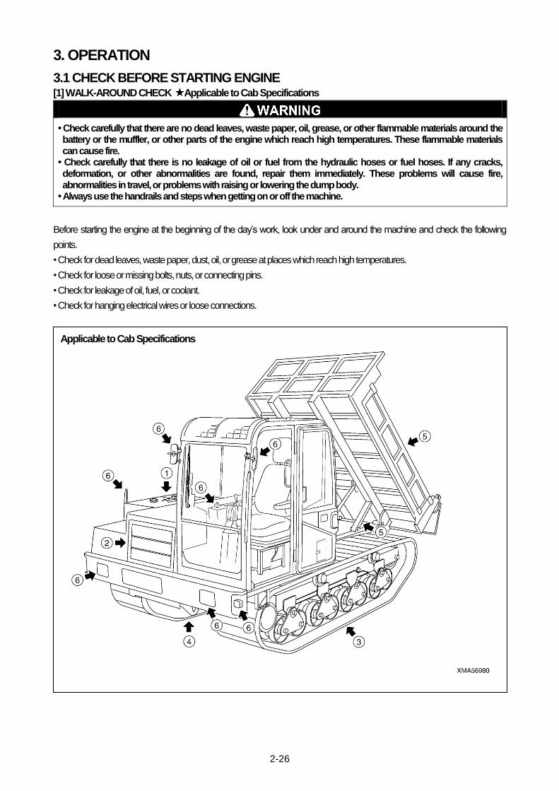
3.1 CHECK BEFORE STARTING ENGINE [1] WALK-AROUND CHECK Applicable to Cab Specifications
• Check carefully that there are no dead leaves, waste paper, oil, grease, or other flammable materials around the battery or the muffler, or other parts of the engine which reach high temperatures. These flammable materials can cause fire.
• Check carefully that there is no leakage of oil or fuel from the hydraulic hoses or fuel hoses. If any cracks, deformation, or other abnormalities are found, repair them immediately. These problems will cause fire, abnormalities in travel, or problems with raising or lowering the dump body.
• Always use the handrails and steps when getting on or off the machine.
Before starting the engine at the beginning of the day’s work, look under and around the machine and check the following
points.
• Check for dead leaves, waste paper, dust, oil, or grease at places which reach high temperatures.
• Check for loose or missing bolts, nuts, or connecting pins.
• Check for leakage of oil, fuel, or coolant.
• Check for hanging electrical wires or loose connections.
Applicable to Cab Specifications

2-27
(1) Check around engine
Check for dead leaves, waste paper, dust, oil, grease, or other flammable materials, and check for leakage of fuel, oil, or coolant
from the engine. Remove any flammable materials, and repair any abnormalities.
Check for hanging electrical wires, loose connections, or signs of burns around the starting motor, alternator, battery, or battery
relay. Repair any abnormality.
(2) Check inside front grill
Check the front surface of the radiator, oil cooler and inter cooler for dead leaves, waste paper, dust, or other flammable
materials or materials which cause clogging. Remove any such materials.
(3) Check undercarriage (rubber crawler, track roller, carrier roller, sprocket, idler)
Check for any wear, breaks, or cracks. Check for any loose or missing nuts or bolts. Tighten if necessary and repair any
abnormalities.
(4) Check under machine
Check the hydraulic tank and fuel tank for leakage, and check the ground under the machine for traces of oil, fuel, or coolant. If
any signs of leakage are found, check for the source of the leakage and repair any abnormality.
Check for loose or missing nuts and bolts from the undercover and other parts, and tighten if necessary.
(5) Check dump body, safety bar
Check for any wear, breaks, or cracks. Check for any loose or missing nuts, bolts, or connecting pins. Tighten if necessary and
repair any abnormalities.
Check for any leakage of oil from the hydraulic hoses or hydraulic cylinders, and repair any abnormality.
(6) Check mirrors, lamps, instrument panel
Check for any damage to the mirrors, lamps, or meters, and repair or replace if there is any abnormality.

2-28
[1] WALK-AROUND CHECK Applicable to Canopy Specifications
• Check carefully that there are no dead leaves, waste paper, oil, grease, or other flammable materials around the battery or the muffler, or other parts of the engine which reach high temperatures. These flammable materials can cause fire.
• Check carefully that there is no leakage of oil or fuel from the hydraulic hoses or fuel hoses. If any cracks, deformation, or other abnormalities are found, repair them immediately. These problems will cause fire, abnormalities in travel, or problems with raising or lowering the dump body.
• Always use the handrails and steps when getting on or off the machine.
Before starting the engine at the beginning of the day’s work, look under and around the machine and check the following
points.
• Check for dead leaves, waste paper, dust, oil, or grease at places which reach high temperatures.
• Check for loose or missing bolts, nuts, or connecting pins.
• Check for leakage of oil, fuel, or coolant.
• Check for hanging electrical wires or loose connections.
Applicable to Canopy Specifications

2-29
(1) Check around engine
Check for dead leaves, waste paper, dust, oil, grease, or other flammable materials, and check for leakage of fuel, oil, or coolant
from the engine. Remove any flammable materials, and repair any abnormalities.
Check for hanging electrical wires, loose connections, or signs of burns around the starting motor, alternator, battery, or battery
relay. Repair any abnormality.
(2) Check inside front grill
Check the front surface of the radiator, oil cooler and inter cooler for dead leaves, waste paper, dust, or other flammable
materials or materials which cause clogging. Remove any such materials.
(3) Check undercarriage (rubber crawler, track roller, carrier roller, sprocket, idler)
Check for any wear, breaks, or cracks. Check for any loose or missing nuts or bolts. Tighten if necessary and repair any
abnormalities.
(4) Check under machine
Check the hydraulic tank and fuel tank for leakage, and check the ground under the machine for traces of oil, fuel, or coolant. If
any signs of leakage are found, check for the source of the leakage and repair any abnormality.
Check for loose or missing nuts and bolts from the undercover and other parts, and tighten if necessary.
(5) Check dump body, safety bar
Check for any wear, breaks, or cracks. Check for any loose or missing nuts, bolts, or connecting pins. Tighten if necessary and
repair any abnormalities.
Check for any leakage of oil from the hydraulic hoses or hydraulic cylinders, and repair any abnormality.
(6) Check mirrors, lamps, instrument panel
Check for any damage to the mirrors, lamps, or meters, and repair or replace if there is any abnormality.

2-30
[2] CHECKS BEFORE STARTING
Before starting the engine at the beginning of the day’s work, carry out the following checks before starting and checks when
required.
For details of the checks before starting, checks when required, and other maintenance, see “MAINTENANCE”.
1. Checks when required
(1) Check, adjust rubber crawler tension
(2) Check rubber crawler for damage, wear
(3) Clean, replace air cleaner
(4) Clean inside of cooling system and change coolant
(5) Check, clean radiator fins, oil cooler fins, inter cooler fins
(6) Check window washer fluid level, add fluid
(7) Check battery electrolyte level, add distilled water
2. Checks before starting
(1) Check, add coolant
(2) Check, add fuel
(3) Check engine lubricating oil level, add oil
(4) Check, add oil to hydraulic tank
(5) Check dust indicator
(6) Check, adjust fan belt tension
(7) Check electrical wiring
(8) Check operation of switches, lamps, gauges
(9) Check operation of horn, alarm buzzer
[3] ADJUST OPERATOR’S SEAT
• Adjust the operator’s seat before operations. Always adjust the operator’s seat after it has been used by another operator.
• Adjust the operator’s seat so that you can operate the travel lever easily with your back against the seat backrest. • Never adjust the seat when traveling. • Always lower the armrest and fasten the seat belt before starting operation. The armrest and seat belt are installed to prevent the danger of the operator falling from the operator’s seat if the machine tips at an angle when traveling.
For details of adjusting the operator’s seat, see “2.10 OPERATOR’S SEAT”.

2-31
3.2 OPERATIONS AND CHECKS BEFORE STARTING ENGINE
1. Check that the left and right travel levers are at the N position.
2. Check that the parking brake switch is at the ON (STOP) position.
3. Check that the dump body is completely lowered and that dump control
lever (1) is at the HOLD position.
4. Check that lock lever (2) of the dump control lever is at the LOCK position.

2-32
3.3 STARTING ENGINE
Check that there are no persons or obstacles in the surrounding area, then sound the horn and start the engine.
NOTICE
• When starting the engine, be sure to press the parking brake switch to set it to the ON (STOP) position. The engine cannot be started without setting the parking brake switch to this ON (STOP) position.
• Do not crank the starting motor continuously for more than 15 seconds. If the engine does not start, wait for at least 2 minutes before trying to start again.
[1] NORMAL STARTING ENGINE
1. Pull the throttle lever back and set it to the low speed position.
2. Insert the key in the starting switch, and turn it to the START position.
3. After the engine starts, release the key.
The key will return automatically to the ON position.
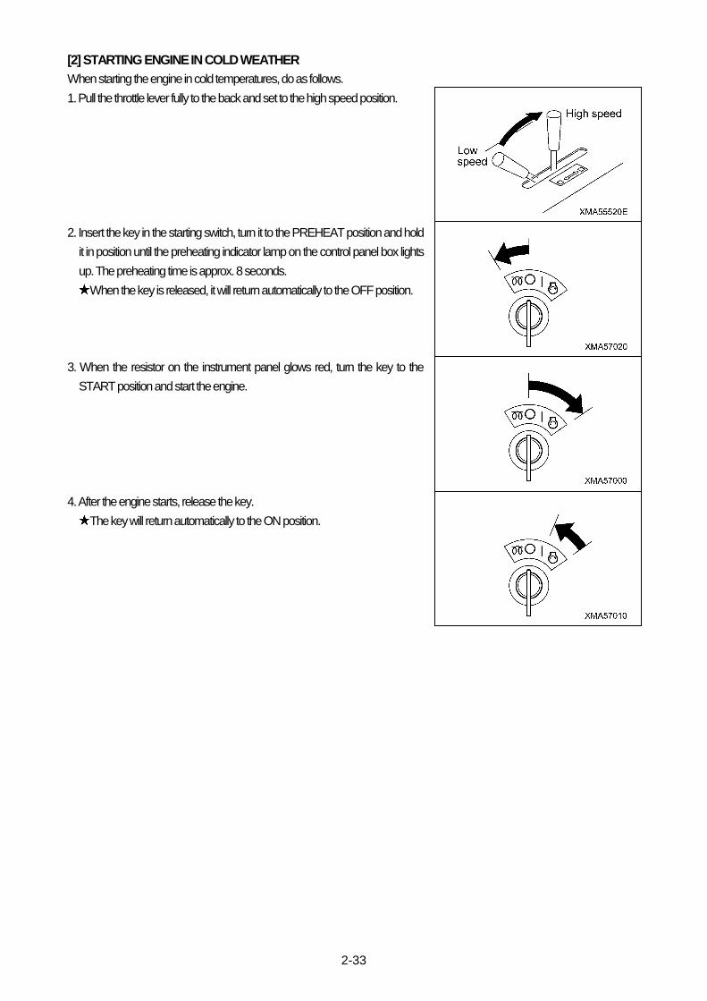
2-33
[2] STARTING ENGINE IN COLD WEATHER
When starting the engine in cold temperatures, do as follows.
1. Pull the throttle lever fully to the back and set to the high speed position.
2. Insert the key in the starting switch, turn it to the PREHEAT position and hold
it in position until the preheating indicator lamp on the control panel box lights
up. The preheating time is approx. 8 seconds.
When the key is released, it will return automatically to the OFF position.
3. When the resistor on the instrument panel glows red, turn the key to the
START position and start the engine.
4. After the engine starts, release the key.
The key will return automatically to the ON position.

2-34
[3] AFTER STARTING (warming-up operation)
NOTICE
Run the engine under light load until the engine coolant temperature is within a green range. Do not suddenly accelerate the engine.
After the engine starts, carry out the warming-up operation as follows.
1. Push the throttle lever forward, set the engine to low speed, and run for
approx. 5 minutes under no load.
2. Pull the throttle lever back, raise the engine to a mid-range speed, and run
for approx. 5 minutes under no load.
3. Operate dump control lever (1) to the RAISE position, raise the dump body
to the maximum height, and run the engine in this condition for approx. 5
minutes.
Keep dump control lever (1) at the RAISE position.
4. Keep dump control lever (1) at the RAISE position, turn the engine throttle
lever to the right (clockwise) further to run the engine at high speed, and run
the engine in this condition for 2 - 5 minutes.
This operation warms up the hydraulic oil and makes the operation of the
travel and dump body smooth.
5. Check that the instrument panel gauges, monitor, charge lamps, parking
brake buzzer, and backup buzzer work normally.
6. Check that there is no abnormality in the exhaust gas color, engine noise, or
vibration.

2-35
3.4 MOVING MACHINE OFF
• Check that there is no one in the area around the machine before starting. Check particularly carefully around the dump body at the rear of the machine.
• When starting the machine off, check that the surrounding area is safe, and sound the horn to inform people that you are starting.
• When starting the machine off, operate the travel lever gradually. The more the travel lever is operated, the faster the machine will travel. Do not start the machine off suddenly.
• When starting uphill on slopes, always start in the low speed range and run the engine at high speed. Keep the travel lever as close as possible to the N position.
• When traveling forward downhill, if the angle of the slope goes above a certain range, the SLOPE CAUTION lamp on the instrument panel lights up and the slope alarm buzzer at the rear of the operator's compartment sounds to warn the operator. It is dangerous to start the machine off with the dump body loaded if the slope alarm buzzer sounds. Reduce the engine to low speed, set the travel lever close to the N position, and start the machine off carefully.
1. Pull the throttle lever back and run the engine at a mid-range speed.
2. Set the parking brake switch to the OFF (RUN) position to release the
parking brake.
Check that the parking brake pilot lamp on the instrument panel goes out
and that the parking brake buzzer stops sounding.
3. Operate the left and right travel levers gradually and start the machine off
slowly.
When starting off in reverse, check that the backup buzzer sounds when
the travel lever is operated to the REVERSE position.

2-36
3.5 SHIFTING SPEED RANGE, CHANGING BETWEEN FORWARD AND REVERSE
• When traveling, select a travel speed to match the travel surface and ground condition. • When traveling on a slope, be sure to set the travel speed range to the low speed range. Also, when traveling on a slope, travel straight forward.
• When going down a slope, always travel in the low speed range. Run the engine at low speed and operate the travel lever a maximum of half way from the N position. Traveling at excessive speed is dangerous and will cause overrunning.
• When traveling up a slope, always travel in the low speed range. Run the engine at the rated speed and keep the travel lever close to the N position. Always travel directly up the slope.
• When traveling forward downhill, if the angle of the slope goes above a certain range, the SLOPE CAUTION lamp on the instrument panel lights up and the slope alarm buzzer at the rear of the operator's compartment sounds to warn the operator. It is dangerous to start the machine off with the dump body loaded if the slope alarm buzzer sounds. Reduce the engine to low speed, set the travel lever close to the N position, and start the machine off carefully.
• If a dangerous state occurs by any possibility, and when it becomes necessary to stop the machine urgently, press the parking brake switch to set it to the ON (STOP) position or turn the engine starting switch to the OFF position to stop the engine.
• When switching between FORWARD and REVERSE, always stop the machine before shifting direction. If the direction of travel is shifted suddenly between FORWARD and REVERSE, it will cause failures such as reverse rotation of the engine.
• When switching the travel speed range, always stop the machine first before operating the switch.
[1] CHANGING SPEED
The travel speed can be changed by changing the amount that the travel lever
is operated.
• The closer the travel lever is to the N position, the lower the travel speed.
• The further the travel lever is from the N position, the higher the travel speed.
[2] SHIFTING BETWEEN FORWARD AND REVERSE
The direction of travel can be changed by changing the direction of operation of
the travel lever.
• When the travel lever is pushed forward, the machine will travel forward.
• When the travel lever is pulled back, the machine will travel in reverse.
Check that the backup buzzer sounds when the travel lever is operated to
the REVERSE position.

2-37
[3] SWITCHING BETWEEN HIGH AND LOW SPEED RANGES
The travel speed range is changed by operating the Hi-Lo speed range
selector switch.
• When the switch is pressed, the mechanism inside the travel motor is
switched and the machine changes to the high speed range.
At the same time, the high-speed lamp on the instrument panel lights up to
show that the machine is traveling in the high speed range.
• If the switch is pressed again, the mechanism inside the travel motor returns
to its original position, and the machine travels in the low speed range.
At the same time, the high-speed lamp on the instrument panel goes out to
show that the machine is traveling in the low speed range.

2-38
3.6 STEERING MACHINE
• Do not turn the machine sharply at high speed; do not carry spin turns unless necessary. This will damage the crawler and hydraulic equipment, and there is also danger that the machine may hit other objects.
• The machine may slip to the side if it is turned on a slope, so avoid turning on slopes as far as possible. Be particularly careful about turning on soft ground of clay ground.
• When traveling forward downhill, if the angle of the slope goes above a certain range, the SLOPE CAUTION lamp on the instrument panel lights up and the slope alarm buzzer at the rear of the operator's compartment sounds to warn the operator. It is dangerous to turn with the dump body loaded if the slope alarm buzzer sounds. Dump the load immediately to empty the dump body, then turn slowly.
• If a dangerous state occurs by any possibility, and when it becomes necessary to stop the machine urgently, press the parking brake switch to set it to the ON (STOP) position or turn the engine starting switch to the OFF position to stop the engine.
[1] GRADUAL TURN
The radius of the turn is determined by the difference in the amount that the left
and right travel levers are operated. The larger the difference between the left
and right travel levers, the smaller the radius of the turn will be.
[Turning while increasing speed]
• To make a gradual turn when traveling forward, push the travel lever forward
a small amount on the opposite side to the direction of the turn.
To make a rapid turn when traveling forward, push the travel lever forward a
large amount on the opposite side to the direction of the turn.
When turning to the left, push the right travel lever forward.
When turning to the right, push the left travel lever forward.
• To make a gradual turn when traveling in reverse, pull the travel lever back a
small amount on the opposite side to the direction of the turn.
To make a rapid turn when traveling in reverse, pull the travel lever back a
large amount on the opposite side to the direction of the turn.
When turning to the left, pull the right travel lever back.
When turning to the right, pull the left travel lever back.

2-39
[Turning while decreasing speed]
• To make a gradual turn when traveling forward, pull the travel lever back a
small amount in the direction of STOP on the same side as the direction of
the turn.
To make a rapid turn when traveling forward, pull the travel lever back a large
amount on the same side as the direction of the turn.
When turning to the left, pull the left travel lever back towards STOP.
When turning to the right, pull the right travel lever back towards STOP.
• To make a gradual turn when traveling in reverse, push the travel lever back
a small amount in the direction of STOP on the same side as the direction of
the turn.
To make a rapid turn when traveling forward, push the travel lever back a
large amount on the same side as the direction of the turn.
When turning to the left, push the left travel lever back towards STOP.
When turning to the right, push the right travel lever back toward
[2] PIVOT TURN
Operate the travel lever on one side and set the other lever at the N position.
Only the crawler on the side that is operated will rotate, so the machine will
make a pivot turn.
To turn to the left when traveling forward, push the right travel lever forward.
To turn to the right when traveling forward, push the left travel lever forward.
To turn to the left when traveling in reverse, pull the right travel lever back.
To turn to the right when traveling in reverse, pull the left travel lever back.
[3] SPIN TURN (Counter rotation turn)
Operate the left and right travel levers in opposite directions. The left and right
crawlers will rotate in opposite directions and the machine will make a spin turn.
To turn to the left, push the right travel lever forward and pull the left travel
lever back.
To turn to the right, push the left travel lever forward and pull the left travel
lever back.

2-40
3.7 STOPPING MACHINE
• Avoid stopping suddenly. Always leave room to spare when stopping. • Never use the parking brake to stop the machine. Using the parking brake will cause the machine to stop suddenly and will also damage the machine.
• When stopping the machine, return the left and right travel levers at the same time to the N position. If the left and right levers are not operated at the same time, there is danger that the brakes will pull to one side.
• When stopping, do not return the travel lever past the N position. If the travel lever is moved past the N position, it will cause failures such as reverse rotation of the engine.
Return the left and right travel levers to the N position.
The hydraulic brake is automatically applied and the machine will stop.
3.8 EMERGENCY STOPPING MACHINE
If a dangerous state occurs by any possibility, and when it becomes necessary to stop the machine urgently, press the parking brake switch to set it to the ON (STOP) position or turn the engine starting switch to the OFF position to stop the engine.
There are following 2 methods when making an emergency stop of the
machine.
• Push in the parking brake switch to apply the parking brake.
• Turn back the starting switch key to the OFF position to stop the engine.

2-41
3.9 PARKING MACHINE
Choose firm, level ground to park the machine. If the machine must be parked on the slope, apply the parking brake and block the tracks to prevent the machine from moving.
Set the parking brake switch to the ON (STOP) position to apply the parking
brake.
Check that the parking brake lamp on the instrument panel lights up and that
the parking brake buzzer sounds.
3.10 STOPPING ENGINE NOTICE
• Do not stop the engine before it has properly cooled down. Stopping the machine before it cools down will shorten the service life of the engine. Never stop the engine suddenly except in emergency.
• If the engine has overheated, do not stop it suddenly. Run the engine at a mid-range speed and gradually cool it down before stopping the engine.
1. Push the throttle lever to the front to reduce the engine speed and run the
engine at idling for 5 minutes to cool the engine down.
2. Return the key in the starting switch to the OFF position.

2-42
3.11 CHECKS AFTER STOPPING ENGINE • Carry out a walk-around check and check the undercarriage, dump body,
and bodywork; check also for leakage of oil and water. If any abnormality is
found, repair it.
• Fill the fuel tank with fuel.
• Remove any dead leaves, waste paper, or other flammable materials from
around the engine that may cause fire.
• Remove any mud or snow stuck to the undercarriage or dump body.
3.12 LOCKING To prevent vandalism, the following locations can be locked.
(1) Cab door Applicable to Cab Specifications
(2) Fuel tank filler cap

2-43
3.13 PRECAUTIONS WHEN TRAVELING
Always follow these precautions when traveling. Failure to follow these precautions may lead to a serious injury or accident.
[1] PERMISSIBLE WATER DEPTH
When operating in water, do not let the bottom surface of the engine oil pan go
below the water surface.
[2] USE OF PARKING BRAKE
When stopping the machine, return the travel lever to the N position. The
hydraulic brake inside the HST is automatically applied to stop the machine.
Never use the parking brake to stop the machine.
Using the parking brake will not only stop the machine suddenly, but will also
cause failure of the travel motor.
Do not use the parking brake to stop the machine except when it is necessary
to stop the machine suddenly in emergencies.
[3] PAY ATTENTION TO ANGLE ALARM BUZZER
If the angle exceeds a certain angle on slopes, the SLOPE CAUTION lamp
on the control panel box lights up and the slope alarm buzzer under the
operator’s seat sounds to warn the operator. It is dangerous to travel with the
dump body loaded if the angle alarm buzzer sounds. Reduce the engine to
low speed, set the travel lever close to the N position, and drive the machine
carefully.
[4] PRECAUTIONS WHEN ENGINE STOPS ON SLOPES
If the engine stops on a slope, do as follows.
1. Return the travel lever to the N position.
2. Press the parking brake switch to the ON (STOP) position.
Check that the parking brake lamp lights up.
3. Start the engine again.
[5] PRECAUTIONS WITH FUEL LEVEL ON SLOPES
If the fuel level in the fuel tank is low and the machine is on a slope or there is
swaying, the engine may suck in air, which may cause the engine to stop.
Always maintain a sufficient level of fuel in the fuel tank.
[6] PRECAUTIONS FOR OIL LEVELS ON SLOPES
When traveling or carrying out operations on steep slopes, check the oil level in
the hydraulic tank and engine, and add oil to the high level.
This will prevent failure caused by lack of oil.

2-44
4. HANDLING DUMP BODY
4.1 OPERATING DUMP BODY
• Always stop the machine before operating the dump body to the dump position. • Position a signalman to ensure safety in the surrounding area, and follow his signals when carrying out the dumping operation.
• Always operate the dump control lever slowly. If the dump body is suddenly stopped or it is allowed to hit the frame when it is lowered, it will cause failures and will also cause problems of safety in the surrounding area.
• When leaving the operator’s compartment with the dump body raised, always lock the dump control lever. In addition, use the safety bar to prevent the dump body from coming down. Even when the engine is stopped, it is possible to lower the dump body.
Operate the dump body as follows.
The further the dump control lever is operated, the faster the dump body will
move.
When the dump control lever is released, it automatically returns to the
HOLD position.
1. Stop the machine completely. For details, see “3.7 STOPPING MACHINE”.
2. Pull the throttle lever back and raise the engine speed sufficiently.
3. Pull the dump control lever (1) up. The dump body will rise.
When the dump body comes near to the max. height, push the dump
control lever down to reduce the speed of the dump body.
4. Push the dump control lever (1) down. The dump body will go down.
When the dump body comes near to the frame, pull the dump control
lever up to reduce the speed of the dump body.
4.2 LOCKING DUMP CONTROL LEVER
If you leave the operator’s seat with the dump track raised, always lock the dump control lever. The dump body can be lowered even when the engine is stopped.
Lock the dump control lever as follows.
1. Release dump control lever (1) and set it to the HOLD position.
2. Push lock lever (2) to inside. This will lock dump control lever (1).
3. To release the lock from the dump control lever, pull lock lever (2) to the
outside. This will release the lock from dump control lever (1).

2-45
4.3 OPERATING SAFETY BAR
• If it is necessary to go under the dump body to carry out inspection and maintenance, always use the safety bar to prevent the dump body from coming down.
• When using the safety bar, check that the bar is fitted securely to the dump body holder. • The safety bar is a safety device used during inspection and maintenance. Do not use the safety bar to support the dump body when replacing the dump cylinder, valve, hydraulic hoses, or other equipment. In such cases always support the dump body with a crane.
NOTICE
When setting the safety bar in position, never start the engine and operate the dump control lever to the LOWER position. If this is done, the safety bar will hit the dump body and may break.
[1] INSTALLING SAFETY BAR
1. Raise the dump body to at least 45 degrees. For details, see “4.1
OPERATING DUMP BODY”.
2. Raise safety bar (1) and set it in holder (2) in the bottom surface of the dump
body.
3. Stop the engine and push the dump control lever down. The dump body will
go down under its own weight.
If the dump body does not go down under it own weight, start the engine
and operate the dump control lever to lower it to a point where the dump
body and safety bar still do not come into contact.
[2] REMOVING SAFETY BAR
1. Raise the dump body fully. For details, see “4.1 OPERATING DUMP
BODY”.
2. Return safety bar (1) to the fixed position on top of the frame.

2-46
4.4 PRECAUTIONS DURING OPERATION
Always follow these precautions when carrying out operations. Failure to follow these precautions may lead to a serious injury or accident.
[1] PRECAUTIONS FOR JOBSITES
• As far as possible, select firm, level ground.
When working on slopes or extremely uneven ground, the change in the center of gravity when the dump is operated may
cause the machine tip over.
• As far as possible, avoid the edge of cliffs or ground which may collapse.
If work must be carried out in such places, set up blocks to prevent the machine from going near the edge or near retaining
walls, or position a signalman and take other necessary steps for ensuring safety.
• When dumping a load from a high point, always position a signalman and follow the signals.
The signalman must always check the safety of the dumping point carefully.
[2] PRECAUTIONS FOR LOAD
• Do not overload the machine.
Do not fit side racks or plates, or make other modifications to extend the size of the dump body to increase the load.
• When loading the dump body, always spread the load uniformly.
Loading the dump body unevenly will cause instability and may cause the machine to tip over.
• Be careful not to let the loading bucket or crane hook hit the dump body or flaps.
• When loading large rocks, first load the dump body with fine soil, then load the rocks on top of that.
• When handling long objects, such as logs or steel beams, load carefully and pay careful consideration to the center of gravity
so that the load does not collapse or sway excessively during hauling operations.
Tie down such loads securely with rope.
If necessary, use blocks and take steps to prevent the rope from slipping.
• When loading stacks of U-shaped ditch liners or concrete blocks, lay a steel sheet and secure with rope, and take other steps
to prevent the load from slipping.

2-47
5. MANUAL RELEASE OF PARKING BRAKE
5.1 OUTLINE OF PARKING BRAKE The parking brake is built into the left and right travel motors.
When the parking brake is released under normal conditions, the parking brake switch is operated and uses the hydraulic
power generated when the engine is running.
If the engine is stopped and there is no hydraulic power, even if the parking brake switch is set to the RUN position, the parking
brake will remain applied.
If any failure should occur in the HST (pump, motor) or engine, and the engine cannot be started again, release the parking
brake manually.
5.2 METHOD FOR MANUAL RELEASE OF PARKING BRAKE
• When releasing the parking brake manually, loosen the hydraulic tank cap slowly, then remove it and wait for the oil temperature to go down fully.
• The circuit inside the HST is still under internal pressure, so when removing plugs and hoses, do not stand directly in front of them; loosen them gradually before removing.
• When the hoses are removed, a large quantity of oil will come out, so always catch the oil in an oil container. • When releasing the parking brake manually, the operation involves dangerous work, such as removing high-pressure hoses, so always pay careful attention to safety during the operation and contact your distributor before starting the operation.
[1] PROCEDURE FOR RELEASING PARKING BRAKE MANUALLY.
When releasing the parking brake manually, do as follows.
1. Remove the undercover. For details, see “2.20 UNDER COVER”.
2. Remove plugs (1) (2 on each side) from the left and right travel motors.
3. Set washer (3) to the supplied bolt (2) (M10 x 100), then pass the bolt
through the plug hole.
4. Turn bolt (2) clockwise to screw it into the thread of brake piston (4) inside the
travel motor.
Screw in bolt (2) until the seat surface of washer (3) contacts the cover.
5. Turn bolt (2) two more turns clockwise.
When this is done, the brake piston is pulled towards the cover and the
parking brake is released.

2-48
[2] PREPARATIONS FOR MOVING FAILED MACHINE
NOTICE
When moving a machine which has had its parking brake released manually, the distance of movement should be only the few meters needed to move it to a safe place. Moving the machine a long distance will cause failure of the HST. When moving a failed machine, carry out the following preparatory work.
Go under the machine and turn adjustment screw (7) of multi-function valves
(6) (4 places) at the bottom of main pump (5) approx. 3.5 turns to the left.
The oil inside the HST circuit will flow freely.
When starting normal operations again after completion of repair of the
machine, always turn adjustment screw (7) of multi-function valve (6) approx.
3.5 turns to the right to return it to the original position.
If the multi-function valve is not returned to the original condition, the machine
will not move.
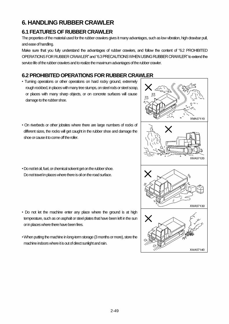
2-49
6. HANDLING RUBBER CRAWLER
6.1 FEATURES OF RUBBER CRAWLER The properties of the material used for the rubber crawlers gives it many advantages, such as low vibration, high drawbar pull,
and ease of handling.
Make sure that you fully understand the advantages of rubber crawlers, and follow the content of “6.2 PROHIBITED
OPERATIONS FOR RUBBER CRAWLER” and “6.3 PRECAUTIONS WHEN USING RUBBER CRAWLER” to extend the
service life of the rubber crawlers and to realize the maximum advantages of the rubber crawler.
6.2 PROHIBITED OPERATIONS FOR RUBBER CRAWLER • Turning operations or other operations on hard rocky ground, extremely
rough rockbed, in places with many tree stumps, on steel rods or steel scrap,
or places with many sharp objects, or on concrete surfaces will cause
damage to the rubber shoe.
• On riverbeds or other jobsites where there are large numbers of rocks of
different sizes, the rocks will get caught in the rubber shoe and damage the
shoe or cause it to come off the roller.
• Do not let oil, fuel, or chemical solvent get on the rubber shoe.
Do not travel in places where there is oil on the road surface.
• Do not let the machine enter any place where the ground is at high
temperature, such as on asphalt or steel plates that have been left in the sun
or in places where there have been fires.
• When putting the machine in long-term storage (3 months or more), store the
machine indoors where it is out of direct sunlight and rain.

2-50
6.3 PRECAUTIONS WHEN USING RUBBER CRAWLER
Always follow these precautions when using rubber crawlers. Failure to follow these precautions may lead to a serious injury or accident.
• Do not make sharp turns on concrete surfaces.
• Do not operate the machine in such away that the rubber track scrapes
against concrete walls.
• Sudden changes of direction will cause damage and premature wear to the
rubber shoes, so avoid sudden turns as far as possible.
• Avoid traveling and turning in places where there is a large ridge. When
traveling over a ridge, approach the ridge at a right angle.
• As far as possible, avoid handling loads that produce oil when crushed (soy
beans, corn, vegetables, etc.). If the machine is used for handling such
products, be sure to wash the track thoroughly after use.
• When handling loads such as salt, ammonium sulphate, potassium chloride,
potassium sulphate, or phosphates, be sure to wash the track thoroughly
after use.
• On snow or frozen road surfaces, the rubber shoe will slip very easily. Be
careful also of slipping when traveling or operating on slopes.
• To prevent the rubber shoe from coming off, always check that the tension is
correct.
If the tension is too loose, the rubber shoe will come off and there will be
abnormal wear of the steel core and sprocket.
If the tension is too tight, the travel speed will be reduced and there will be
premature wear or damage to the undercarriage.

2-51
7. TRANSPORTATION
7.1 LOADING, UNLOADING WORK
• Make sure the ramp has sufficient width, length and thickness to enable the machine to be safely loaded and unloaded. If the ramp sags appreciably, reinforce it with blocks, etc.
• When loading and unloading the machine, park the trailer on a flat firm roadbed. Keep a fairly long distance between the road shoulder and the machine.
• Remove the mud from the undercarriage to prevent the machine from slipping to the side on slopes. Be sure the ramp surface is clean and free of grease, oil, ice and loosen materials.
• Never change the direction of travel when on the ramps. If it is necessary to change direction, drive off the ramps and correct the direction, then drive on to the ramps again.
When loading or unloading, always use ramps or a platform and carry out the operations as follows.
1. Apply the brake securely to the truck or trailer and put blocks under the tires
to prevent the machine from moving.
2. Set the ramps so that the center of the machine is aligned with the truck or
trailer, and fix securely in position.
Check that the left and right ramps are at the same height.
3. Align the machine with the ramps, and drive up or down the ramps slowly to
the load or unload the machine.
4. To prevent the machine from moving during transportation, put wooden
blocks under the front and rear of the rubber crawler and secure the
machine with chains or wire rope.
Be particularly careful to secure it so that it cannot slip to the side.
7.2 PRECAUTIONS FOR LOADING
When loading and unloading the machine, park the trailer on a flat firm roadbed. Keep a fairly long distance between the road shoulder and the machine.
After loading the specified position, secure the machine as follows.
1. Lower the dump body slowly.
2. Push the parking brake switch in to apply the parking brake.
3. Return the engine throttle lever to the low-speed position, turn the starting switch to the OFF position and stop the engine.
Remove the starting key.
4. When transporting the machine, place rectangular timber underneath the front and rear track shoes to prevent the machine
from moving about. Also, hold it down with chains or rope. Be particularly careful to ensure that the machine does not slip
sideways.
7.3 PRECAUTIONS FOR TRANSPORTATION
Determine the route for transporting the machine by taking into account the width, height and weight of the machine.
Obey all state and local laws governing the weight, width and length of a load. Observe all regulations governing wide loads.

2-52
8. COLD WEATHER OPERATION
8.1 PRECAUTIONS FOR LOW TEMPERATURE If the temperature becomes low, it becomes difficult to start the engine, and the coolant may freeze, so do as follows.
[1] FUEL AND LUBRICANTS
Change to fuel and oil with low viscosity for all components.
For details of the specified viscosity, see “MAINTENANCE 3. USE OF FUEL, COOLANT AND LUBRICANTS
ACCORDING TO AMBIENT TEMPERATURE”.
[2] COOLANT MIXTURE RATIO IN COOLING WATER
Antifreeze is flammable, so keep it away from flames. Never smoke when handling antifreeze. Antifreeze is added to the coolant to prevent the water from freezing when the machine is not being used.
NOTICE
Never use methanol, ethanol, or propanol-based antifreeze.
To prevent engine overheating, rust, corrosion or freezing in the cooling system, use a mixture of long life coolant with tap water
for engine cooling water.
The coolant serves anti-rust, anti-corrosion, and antifreeze. It should be used year around.
The coolant mixture ratio must be 30% or higher to ensure anti-rust and anti-corrosion properties.
[COOLANT MIXTURE RATIO]
Use the following table as a guide. The table shows examples when the amount of cooling water is "13 liters (3.43 US gal)
[2.86 UK gal]".
Item Unit
Min. temperature Deg C -10 -15 -20 -25
Deg F 14 5 -4 -13
Amount of coolant
Litter 3.9 3.9 4.5 5.3
US gal 1.03 1.03 1.19 1.40
UK gal 0.86 0.86 0.99 1.17
Amount of cooling water
Litter 9.1 9.1 8.5 7.7
US gal 2.40 2.40 2.24 2.03
UK gal 2.00 2.00 1.87 1.69
Coolant mixture ratio % 30 30 35 40
When the vehicle is delivered, the cooling water is mixed with 30% long life coolant of the brand as shown below.
COOLANT GREEN (ENEOS): Non-amine type

2-53
[3] BATTERY
• To avoid gas explosions, do not bring fire or sparks near the battery. • Battery electrolyte is dangerous. If it gets in your eyes or on your skin, wash it off with large amounts of water, and consult a doctor.
When the ambient temperature drops, the capacity of the battery will also drop. If the battery charge ratio is low, the battery
electrolyte may freeze. Maintain the battery charge as close as possible to 100%, and insulate it against cold temperature so
that the machine can be started easily the next morning.
Measure the specific gravity and calculate the rate of charge from the following conversion table.
Rated of charge (%) Temp. of battery electrolyte [deg C (deg F)]
20 (68) 0 (32) -10 (14) -20 (-4)
100 1.28 1.29 1.30 1.31
90 1.26 1.27 1.28 1.29
80 1.24 1.25 1.26 1.27
75 1.23 1.24 1.25 1.26
8.2 AFTER COMPLETION OF WORK To prevent mud, water, or the undercarriage from freezing and making it impossible for the machine to move on the following
morning, always observe the following precautions.
• Mud and water on the machine body should be completely removed. This is to prevent damage to the seal caused by mud
or dirt getting inside the seal with frozen drops of water.
• Park the machine on concrete or hard ground. If this is impossible, park the machine on wooden boards.
• Open the drain valve and drain any water collected in the fuel system to prevent it from freezing.
• As the battery capacity drops markedly in low temperatures, cover the battery or remove it from the machine, keep it in a
warm place, and install it again the next morning.
• If electrolyte level is found low, add distilled water in the morning before beginning work. Do not add the water after day’s work
so as to prevent fluid in the battery from freezing in the night.
8.3 AFTER COLD WEATHER When season changes and the weather becomes warmer, do as follows.
• Replace the fuel and oil for all parts with oil of the viscosity specified.
For details, see “MAINTENACE 3. USE OF FUEL, COOLANT AND LUBRICANTS ACCORDING TO AMBIENT
TEMPERATURE”.
• If for any reason permanent antifreeze cannot be used, and an ethyl glycol base antifreeze (winter, one season type) is used
instead, or if no antifreeze is used, drain the cooling system completely, then clean out the inside of the cooling system
thoroughly, and fill with fresh water.

2-54
9. LONG-TERM STORAGE
9.1 BEFORE STORAGE When putting the machine in storage for more than one month, do as follows.
• After every part is washed and dried, the machine shall be housed in a dry building. Never leave it outdoors.
In case it is indispensable to leave it outdoors, park the machine on the flat ground and cover it with canvas etc.
• Completely fill the fuel tank, lubricate and change the oil before storage.
• Apply a thin coat of grease to metal surface of the hydraulic piston rods and the idler adjusting rods.
• Disconnect the negative terminals of the battery and cover it, or remove it from the machine and store it separately.
• If the temperature will go below 0℃, add anti-freeze to the cooling water.
When not using anti-freeze, drain all the cooling water, and put a "No coolant" sign in the operator's compartment.
9.2 PRECAUTIONS DURING STORAGE
If warming-up operation must be carried out inside a building, open the windows and doors to ensure good ventilation and prevent gas poisoning.
• When the machine is in long-term storage, start the engine once a month and carry out the warming-up operation thoroughly.
In addition, move the machine for a short distance, and carry out the raise and lower operation thoroughly for the dump body.
If the cooling water has been drained from the machine, always fill with cooling water before starting the engine.
Before operating the dump body, wipe off the coat of grease from the piston rods of the hydraulic cylinders.
9.3 PRECAUTIONS AFTER STORAGE Carry out the following procedure when using the machine after long-term storage.
• Wipe off the coat of grease from the piston rods of the hydraulic cylinders.
• Remove the drain plugs from the hydraulic tank, fuel tank, engine oil pan, and travel motors, and drain the water.
• Drain the water from the engine oil filter, fuel filter, and hydraulic line filter.
• Carry out the checks before starting and warm up the machine thoroughly, then check all parts of the machine carefully.

2-55
10. HANDLING BATTERY
When handling batteries, always do as follows.
• Before working with the battery, stop the engine and turn the key in the starting switch to the OFF position.
• When working with the battery, always wear safety glasses. • Batteries generate hydrogen gas, so there is danger of explosion. Do not smoke, use a lighter, or create any spark near the battery.
• Battery electrolyte contains sulphuric acid. If you get acid on yourself, immediately flush the area with large amounts of water. If acid gets into your eyes, flush them immediately with large amounts of fresh water, then go to a doctor for treatment.
• When removing the battery, first disconnect the negative (-) terminal of the cable from the ground. When installing, install the positive (+) terminal first.
• If a tool touches the cable connecting the positive terminal and the chassis, there is danger that it will cause sparks. Do not carry tools in your breast pocket.
• Defective contact caused by loose battery terminals can generate sparks and lead to an explosion. Tighten the battery terminals securely.
10.1 PRECAUTIONS WHEN HANDLING BATTERY • Always be careful not to let the battery become discharged.
Do not wait for the battery to become discharged before recharging it; measure the specific gravity of the battery electrolyte
beforehand and charge the battery if necessary.
Always keeping the battery in good condition will extend the life of the battery.
• When operating the machine in high temperatures, check the level of the battery electrolyte at shorter intervals than specified
for periodic inspection and maintenance.
• When working in low temperatures, the capacity of the battery will drop considerably, so maintain the battery charge as close
as possible to 100%, and insulate it against cold temperatures so that the machine can be started easily the next morning.
When adding distilled water, to prevent the electrolyte from freezing, always add the distilled water immediately before starting
operations on the following morning.

2-56
10.2 REMOVAL AND INSTALLATION OF BATTERY The battery is installed in front of the fuel tank on the front right side of the machine.
[1] REMOVAL
1. Open the inspection cover. For details, see “2.15 BATTERY INSPECTION
COVER”.
2. Raise the rubber cover (1) on the battery and move it to inspection cover.
3. Remove locknuts (2) (left and right: x 2), then remove plate (3).
4. Disconnect the battery cable from negative (-) terminal (4) for the ground,
then disconnect at positive (+) terminal end (5) and cable (6) connecting the
batteries.
5. Remove 2 batteries (7).
[2] INSTALLATION
Install the batteries in the reverse order to removal.
When connecting the battery cables, always install the negative (-) terminal
(4) at the ground end last.
10.3 PRECAUTIONS WHEN CHARGING BATTERY If the battery becomes discharged or the battery charge is low, charge the battery.
To charge the battery when it is still mounted on the machine, do as follows.
It is dangerous if the temperature of the battery electrolyte exceeds 45℃ during charging, so stop charging and
wait for the temperature to go down.
• Disconnect the wiring from the battery terminals before charging.
There is danger of abnormal voltage being applied to the alternator and damaging it.
When disconnecting the wiring, always disconnect the negative (-) terminal wiring first; and when connecting the wiring,
always connect the negative (-) terminal wiring last.
• During charging, remove all the plugs from the battery cells to allow any gas to escape.
• When the charging is completed, stop the charging immediately.
If the battery is overcharged, overheating of the battery will cause damage to the battery.
Reference: Measure the specific gravity and calculate the rate of charge from the following conversion table.
Rated of charge (%) Temp. of battery electrolyte [deg C (deg F)]
20 (68) 0 (32) -10 (14) -20 (-4)
100 1.28 1.29 1.30 1.31
90 1.26 1.27 1.28 1.29
80 1.24 1.25 1.26 1.27
75 1.23 1.24 1.25 1.26

2-57
10.4 STARTING ENGINE WITH BOOSTER CABLE If the battery is discharged and booster cables are used to start the engine, do
as follows
• Be careful not to let the normal machine and problem machine contact each other.
• When connecting the cables, never let the positive (+) and negative (-) terminals contact each other.
• Make sure that there is no mistake in the booster cable connection. When the final connection is made to the negative (-) terminal, sparks will be generated, so do not connect to the negative (-) terminal of the battery on the problem machine. Connect to the engine block.
• When starting the engine with a booster cable, always wear safety glasses.
NOTICE
• The size of the booster cable and clip should be suitable for the battery capacity. Check that they are not corroded or damaged.
• The battery on the normal machine must be the same capacity as that on the problem machine.
[1] CONNECTING THE BOOSTER CABLES
★The numbers in the diagram on the right show the order for
connecting the cables.
1. Make sure that the starting switches of the normal machine and
problem machine are both at the OFF position.
2. Connect the clips at the ends of booster cable A to the positive (+)
terminal of the problem machine and the normal machine.
3. Connect one clip of booster cable B to the negative (-) terminal of the
normal machine.
4. Connect the other clip of booster cable B to the engine block of the
problem machine.
5. Start the problem machine.
[2] DISCONNECTING THE BOOSTER CABLE
★The numbers in the diagram on the right show the order for
connecting the cables.
When the engine on the problem machine starts, remove the cables in
the reverse order to connecting.

2-58
11. TROUBLESHOOTING
If it is felt that there is any abnormality, investigate the cause immediately and take the necessary action to prevent any serious
failure.
If the cause is unknown, please contact your distributor for repairs.
When contacting your distributor, please give the machine serial number and engine number.
11.1 PROBLEMS WITH ENGINE RELATED PARTS Problem Main causes Remedy
Starting motor does not turn when starting switch is turned to START
• Insufficient battery charge • Defective wiring • Failure in starting motor, relay
• Charge • Check, repair • Contact your distributor
Starting motor turns, but cranks engine slowly
• Insufficient battery charge • Defective ground connection wiring • Viscosity of engine oil is too high
• Charge • Check, repair • Change to proper viscosity
Starting motor turns, but engine does not start
• Lack of fuel • Air in fuel line • Failure in fuel injection pump •Failure in engine
• Check, add fuel • Bleed air • Contact your distributor • Contact your distributor
After warming-up operation, [Engine oil pressure lamp] on instrument panel stays lighted up even when engine speed is raised (Engine oil pressure does not rise)
• Lack of engine oil • Clogged engine oil filter • Failure in engine parts
• Check, add oil • Replace new parts • Contact your distributor
Engine water temperature gauge points to around red range, or steam spurts out from near radiator system
• Lack of coolant • Leakage of oil from coolant system • Loose fan belt • Clogged radiator fin • Defective thermostat • Overloading, operation under excessive load
• Check, add water • Check, repair or ccontact your distributor
• Check, adjust, or replace new belt • Check, clean • Replace new parts • Reduce to below max. payload
Engine water temperature gauge points does not reach around green range
• Defective thermostat • Defective engine water temperature gauge
• Replace new parts • Replace new parts
Engine exhaust color is white • Engine oil level is too high • Improper fuel
• Adjust to correct amount • Change to specified fuel
Engine exhaust color is too black • Clogged air cleaner • Improper fuel • Failure in engine
• Check, clean • Change to specified fuel • Contact your distributor

2-59
Problem Main causes Remedy
Engine does not run smoothly
• Air in fuel line
• Fuel filter clogged with dirt, water in
fuel filter
• Leakage of fuel from fuel system
• Failure in engine
• Bleed air
• Check, replace new parts, or repair
• Check, repair
• Contact your distributor
Engine stops when set to low speed • Failure in engine • Contact your distributor
Engine suddenly stops during operation
• Lack of fuel
• Lack of engine oil
• Failure in engine
• Check, add fuel
• Check, add oil
• Contact your distributor
11.2 PROBLEMS WITH CHASSIS RELATED PARTS Problem Main causes Remedy
Machine does not move
• Parking brake still applied • Leakage of oil from hydraulic system • Travel lever cable disconnected • Failure in hydraulic equipment
• Release parking brake, or check brake piping
• Check, repair • Check, repair • Contact your distributor
HST oil pressure lamp on instrument panel lights up during operation (HST oil pressure is lowered)
• Clogged hydraulic line filter • Clogged strainer inside hydraulic tank
• Defective wiring • Failure in hydraulic equipment
• Check, clean • Check, clean • Check, repair • Contact your distributor
Abnormal noise generated from around pump
• Clogged strainer inside hydraulic tank
• Leakage of oil from hydraulic system • Failure in hydraulic equipment
• Check, clean, or replace new parts • Check, repair • Contact your distributor
HST oil temperature lamp on instrument panel lights up during operation (Hydraulic oil temperature rises too high)
• Lack of oil inside hydraulic tank • Loose fan belt • Clogged oil cooler fins • Leakage of oil from hydraulic system • Operation under excessive load
• Check, add oil • Check, adjust or replace • Check, clean • Check, repair • Operate within max. payload
Rubber crawler comes off • Rubber crawler tension too loose • Check, adjust
Abnormal wear of sprocket • Rubber crawler tension too tight • Check, adjust

2-60
11.3 PROBLEMS WITH ELECTRIC RELATED PARTS Problem Main causes Remedy
Battery charge lamp on instrument panel lights up during operation (Battery is not charging)
• Defective wiring • Blown fuse at rear of instrument panel
• Loose fan belt • Defective alternator • Defective battery function
• Check, repair • Check, replace • Check, adjust or replace • Contact your distributor • Check, repair or replace
Head lamp is not bright • Battery charge is too low • Defective alternator
• Charge • Contact your distributor
No lamps light up • Blown fuse • Defective wiring • Defective lamp switch
• Check, replace • Check, repair • Check, replace
Individual head lamps, gauge lamps do not light up
• Blown bulb • Defective wiring
• Replace • Check, repair
Horn does not sound • Blown fuse • Defective wiring • Defective horn
• Check, replace • Check, repair • Check, replace
Left, right turn signal lamps do not flash
• Blown fuse • Defective wiring • Defective flasher relay • Defective flasher switch
• Check, replace • Check, repair • Check, replace • Check, replace
Parking brake buzzer does not sound
• Blown fuse • Defective wiring • Defective buzzer • Defective parking brake switch
• Check, replace • Check, repair • Check, replace • Check, replace
Backup buzzer does not sound
• Blown fuse • Defective wiring • Defective buzzer • Defective backup switch
• Check, replace • Check, repair • Check, replace • Check, adjust or replace
Slope alarm buzzer does not sound
• Blown fuse • Defective wiring • Defective buzzer • Defective slope alarm unit
• Check, replace • Check, replace • Contact your distributor • Contact your distributor

3-1
MAINTENANCE
1. Basic outline of maintenance 3- 2
2. Precautions for maintenance 3- 4
3. Use of fuel and lubricants according to ambient temperature 3- 6
4. Tools and tightening torques 3-8
5. Periodic replacement of critical parts 3-10
6. Maintenance schedule chart 3-12
7. Service procedure 3-13

3-2
1. BASIC OUTLINE OF MAINTENANCE
[1] OIL
• Oil is used under extremely heavy-duty conditions (high temperature, high pressure) in the engine, hydraulic pump, motor,
and work equipment. Therefore, it deteriorates as time passes.
Always use the grade of oil and the oil which matches the ambient temperature listed in this operation manual.
Even if the oil is not dirty, always change it at the specified interval.
• When adding oil, do not mix oils of different grades or brands.
• Always add oil to the specified oil level. Too much oil and too little oil are both the cause of problems.
• When changing the oil, always replace the related oil filter at the same time.
• Always be careful when handling oil to prevent water, dirty, or other impurities from getting into the oil.
A large proportion of problems with the machine are caused by impurities getting into the oil, so be extremely careful not to let
impurities get into the oil: always store the oil indoors and carry out oil-filling operations in a dust-free environment.
• If the oil is a milky white, there is probably water or air in the circuit. In such cases, please contact your distributor.
[2] FUEL
• Do not use any fuel except diesel oil.
• Always use the fuel specified for the ambient temperature listed in this operation manual.
• The fuel pump is a precision instrument, so if fuel containing water or dirt is used, the fuel pump will stop working. Be extremely
careful not to let impurities get into the fuel: always store the fuel indoors and carry out refueling operations in a dust-free
environment.
• If fuel is stored in drum cans, store the drum cans on their sides so that the ports in the drum cans are in a straight line to the
side. This action will prevent damp air from being sucked in.
• To prevent moisture in the air from getting into the fuel tank, always fill the tank after the completion of each day's work.
• If the machine runs out of fuel, or when the fuel filter has been replaced, it is necessary to bleed the air the circuit.
Always read the separate operation manual for the engine when carrying out this operation.
[3] COOLANT
• Do not use river water, well water, or water from simple water lines as the coolant.
Such kinds of water contain many impurities, such as calcium and dirt, so scale will collect inside the engine and radiator. This
will cause improper heat exchange, and will lead to overheating.
• If the engine overheats, allow the engine to cool down, then add coolant.
• When using antifreeze, always follow the precautions given in the operation manual.
[4] GREASE
• Grease is used at the connecting points of the dump body or travel lever linkage to prevent gouging or noise.
• The grease nipples not listed in this manual are nipples used for overhaul, so there is no need to add grease to them.
However, if any gouging or noise occurs during use, add grease.
• When adding grease, pump in grease until the old grease is completely forced out, then wipe off all the old grease. Be
particularly careful to wipe off the grease at points where mud and dirty may stick and cause wear of the rotating parts.

3-3
[5] FILTERS
• Filters are used to prevent trouble caused when impurities in the oil, fuel, or air enter important equipment. When the
replacement interval listed in this manual is reached, always replace or clean the filters.
However, when using this machine under heavy-duty conditions, replace the filters before the specified replacement interval
has passed.
• Do not wash and reuse oil filters or fuel filters. Always replace them with new parts.
• When replacing the oil filter, check the old filter for any metal particles or pieces of rubber from the hoses.
If any rubber or metal is found, please contact your distributor. This action is important to prevent any failure before it occurs.
• When using new filters, do not remove the wrapping until immediately before using them.
[6] ELECTRICAL COMPONENTS
• It is extremely dangerous if electrical components become wet or the film covering them is broken. This may lead to electrical
leakage and may cause misoperation of the machine. When washing the machine, take care not to get water onto electrical
components.
• Never remove any electrical components from the machine or disassemble them.
• Always contact your distributor before installing additional electrical equipment to your machine.
• After the machine has been used near the sea or after it has been used for spreading fertilizer, wipe the electrical components
carefully with a dry cloth to prevent corrosion.
[7] HYDRAULIC SYSTEM
• The hydraulic equipment is at high temperature and high pressure during operations and immediately after operations have
been completed.
When carrying out inspection and maintenance of the hydraulic equipment, always do as follows.
(1) Stop the machine on level ground, and lower the work equipment to the ground so that there is no pressure in the
hydraulic cylinder circuit.
(2) Always stop the engine.
(3) Loosen the hydraulic tank cap slowly, then remove it.
(4) Always wait for the temperature to go down before starting maintenance. Even when the temperature goes down, the
circuits are still under internal pressure, so when removing plugs or hoses, do not stand directly in front of them, and loosen
the connections slowly before removing.
• If high-pressure hoses, connections, or hydraulic equipment have been removed, always replace the O-ring.
• When replacing or cleaning the hydraulic line filter or strainer, or when replacing or repairing the hydraulic equipment or hoses,
always bleed the air from the circuit after completion of the operation.

3-4
2. PRECAUTIONS FOR MAINTENANCE
• Before carrying out inspection and maintenance, always read “2. PRECAUTIONS FOR INSPECTION AND MAINTENANCE in the SAFETY” volume and make sure that you understand the safety procedures for operations.
• Do not carry out any operation not listed in this manual for inspection and maintenance. When carrying out inspection and maintenance of the engine, always read the separate engine operation manual and make sure that you understand it.
[1] CHECK HOURMETER
• Read the hourmeter every day to check if the required interval has been reached for any maintenance item.
[2] USE GENUINE PARTS
• When replacing parts, always use the genuine parts specified in the parts list.
[3] PRECAUTIONS WHEN ADDING OR CHANGING OIL OR GREASE
• When adding or changing fuel, oil, or grease, always use the type specified by Morooka. Be sure to use the viscosity specified
for the ambient temperature.
• Never mix types of oil or brands of oil from different makers.
• The oil used when the machine is shipped from the factory is as shown in the table below.
Item Type Brand
Engine oil pan CF class DH-1 10W-30 -
Hydraulic tank Hydraulic oil ISO VG46 Idemitsu Kosan Super Hydro X 46
Travel motor reduction gear case SAE90 GL-5 Shin Nihon Sekiyu Gear Lube SP 90
[4] PRECAUTIONS WHEN WASHING OR CLEANING MACHINE
1. Wash or clean the machine to make it easier to locate problem points. In particular, wash the oil filler, level gauge, and
greasing plugs to prevent dirt or mud from entering when adding oil or grease.
2. Cover electrical parts, such as the starting motor or alternator, with a sheet to prevent water from getting on them.
3. Do not carry out high-pressure washing for the radiator or oil cooler parts.
[5] BE CAREFUL OF OIL AND COOLANT TEMPERATURE
1. It is dangerous to drain the oil or coolant or replace the filters immediately after stopping the engine. Wait for the machine to
cool down before carrying out such operations.
2. When draining the oil, warm up the oil to a suitable temperature (approx. 20 – 40 deg C) before carrying out the operation.
[6] PRECAUTIONS WHEN CHECKING OIL LEVEL, ADDING OIL
1. When checking the oil level or adding oil, choose a place where there is no dust to prevent dirt from entering the oil line.
2. Use clean oil and grease. Use a clean container to prevent dirt from getting in.
3. If there is a strainer fitted to the oil filler port, do not remove the strainer when adding oil.
4. Check that the lubricating oil is at the correct level. The oil level should not be too high or too low.

3-5
[7] CHECKING DRAINED OIL, FILTER
• When the oil has been changed or the filter replaced, always check the drained oil and removed filter to check for metal
particles or other foreign materials.
[8] SETTING UP WARNING SIGNS
• When the oil or coolant has been drained, put warning signs (Part No.: 1-41010-1210) in the operator's compartment to
prevent anyone from starting the engine by mistake.
[9] PRECAUTIONS WHEN WASHING PARTS
• When washing parts, use a non-flammable washing agent or diesel oil.
When using diesel oil, do not bring lighted cigarettes or cigarette lighters close.
[10] PRECAUTIONS WHEN INSTALLING PARTS
• When O-rings, gaskets, or other seals are used for the mounting surface, clean the mounting surface and always replace the
seal with a new part.
[11] PRECAUTIONS WHEN CARRYING OUT INSPECTION AND MAINTENANCE OF A MACHINE AFTER
OPERATIONS IN DUSTY AREAS
• Check carefully for clogging of the air cleaner, and clean the air cleaner element more frequently.
• Clean the radiator core, oil cooler core and inter cooler core more frequently to prevent clogging.
• Replace the fuel filter more frequently.
• Clean electrical parts carefully (in particular, the starting motor or alternator) to prevent dust from collecting.
[12] PRECAUTIONS WHEN CARRYING OUT INSPECTION AND MAINTENANCE ON MACHINES BEFORE
STARTING OPERATIONS IN SWAMPY AREAS, RAIN, RIVERBEDS, OR SNOW
• Before starting operations, check that the drain plug under the engine and the greasing plugs for the track rollers are securely
tightened.
• After completion of operations, wash the machine carefully and check for cracks and damage, and for loose or missing nuts
and bolts.

3-6
3. USE OF FUEL AND LUBRICANTS ACCORDING TO AMBIENT
TEMPERATURE
3.1 FUEL, COOLANT, AND LUBRICANT TABLE NOTICE
• The quality of engine oil influences significantly on the engine performance and start ability. Always use the engine oil of CG-4 class or CAT diesel engine oil Cat DEO and of specified viscosity (refer to the table below) according to the ambient temperatures.
• Always use diesel fuel. Never use additives such as anti-freeze and water-removing agents. Otherwise, the fuel injection system may be damaged. Never use kerosene, as it may cause a trouble.
• Select the fuel and oil from the table below according to the ambient temperature.
• The specified capacity is the total amount of oil, including the oil in the piping of the various components.
• The refill capacity is the amount of oil added when changing the oil during inspection and maintenance.
• When starting the engine in an ambient temperature of lower than 0 deg C, always use a grade specified for temperatures
below 0 deg C, even if the temperature goes up to 10 deg C during the daytime.
• For the coolant mixture ratio of cooling water, see "Operation 8. Cold Weather Operation" in "[2] Coolant Mixture Ratio in
Cooling Water ".

3-7
REMARK
• When fuel sulphur content is less than 0.5 %, change oil in the oil pan every periodic maintenance hours described in this
manual.
Change oil according to the following table if fuel sulphur content is above 0.5%.
Fuel sulphur content Change interval of oil in engine oil pan
0.5 to 1.0% 1/2 of regular interval
Above 1.0% 1/4 of regular interval
• When starting the engine in an atmospheric temperature of lower than 0 deg C, be sure to use engine oil of SAE10W-30 and
SAE15W-40, even though an atmospheric temperature goes up to 10 deg C more or less in the day time.
• Use API classification CD as engine oil and if API classification CC, reduce the engine oil change interval to half.
• There is no problem if single grade oil is mixed with multigrade oil (SAE10W-30, 15W-40), but be sure to add single grade oil
that matches the temperature in the table.
• We recommend genuine oil which has been specifically formulated and approved for use in engine and hydraulic work
equipment applications.
Specified capacity: Total amount of oil including oil for components and oil in piping.
Refill capacity: Amount of oil needed to refill system during normal inspection and maintenance.
ASTM: American Society of Testing and Material
SAE: Society of Automotive Engineers
API: American Petroleum Institute
• Hydraulic oil: Nihon Sekiyu Highland Wide KV46.
When changing the hydraulic oil, please contact your distributor.

3-8
4. TOOLS AND TIGHTENING TORQUES
4.1 INTRODUCTION OF NECESSARY TOOLS The following tools are needed when carrying out maintenance.
If the tools are broken or worn, please order new tools from your distributor.
No. Name of tool Part No. Remarks
1 Wrench set 0-9100-00000 Width across flats (S1 x S2)
0-9100-00709 7mm x 9mm
0-9100-00810 8mm x 10mm
0-9100-01113 11mm x 13mm
0-9100-01214 12mm x 14mm
0-9100-01719 17mm x 19mm
0-9100-02224 22mm x 24mm
2 Wrench 0-9105-04600 Width across flats 46mm
3 Screw driver (+) 0-9210-00150
4 Screw driver (-) 0-9200-00200

3-9
4.2 TORQUE LIST FOR BOLTS AND NUTS Unless otherwise specified, tighten the metric bolts and nuts to the torque shown
in the table below.
The tightening torque is determined by the width across flats (b) of the nut and
bolt.
NOTICE
When tightening panels or other parts with tightening fixtures made of plastic, be careful not to use excessive tightening torque. Tightening excessively will damage the plastic parts. Be extremely careful when tightening.
Thread diameter x Width across thread pitch flats
(a) (mm x mm)
Width across flats (b) (mm)
Tightening torque (kgf-m) {N-m}
Tensile strength 4T Tensile strength 11T
3x0.5 5.5 0.05 {0.5} 0.2 {1.8}
4x0.7 7 0.1 {1.0} 0.4 {4.1}
5x0.8 8 0.2 {2.2} 0.8 {8.2}
6x1.0 10 0.4 {3.6} 1.4 {14.0}
8x1.25 13 0.9 {8.9} 3.5 {34.0}
10x1.5 17 1.8 {17.7} 6.9 {67.4}
12x1.75 19 3.2 {30.9} 12.0 {117}
14x2.0 22 5.0 {49.1} 19.1 {187}
16x2.0 24 7.8 {76.7} 29.7 {291}
18x2.5 27 10.7 {105} 40.9 {401}
20x2.5 30 15.3 {149} 58.1 {570}
22x2.5 32 20.8 {203} 79.0 {775}
24x3.0 36 26.4 {258} 100 {983}
27x3.0 41 38.6 {378} 147 {1440}
30x3.5 46 52.4 {513} 199 {1955}
33x3.5 50 71.3 {699} 271 {2660}
36x4.0 55 91.6 {898} 348 {3416}
39x4.0 60 119 {1162} 451 {4421}

3-10
5. PERIODIC REPLACEMENT OF CRITICAL PARTS
5.1 PERIODIC REPLACEMENT INTERVAL (EVERY 2 YEARS) In order to further increase the safety of the machine Morooka recommends periodic inspection and replacement of critical
parts (hydraulic hoses, fuel hoses, etc.) which are related to causes of fire and to efficiency in the raising and lowering of the
dump body and traveling and stopping functions of the machine.
With these parts, the material changes as time passes, and they easily wear or deteriorate. However, it is difficult to judge the
condition of the parts simply by periodic maintenance, so they should always be replaced after a fixed time has passed,
regardless of their condition. Always replace them with new genuine parts to ensure that the machine always maintains its
function completely.
5.2 PERIODIC INSPECTION
• Check the hydraulic hoses and fuel hoses carefully to check for cracks, deterioration, or other damage, and to check that there is no leakage from the connections. When carrying out checks before starting, always check the ground under the machine to check for traces of oil leakage.
• When replacing the hydraulic hoses or fuel hoses, always order genuine parts. Never use any imitation or substitute parts.
• When any hydraulic hose is replaced, always replace the O-rings at the same time. Failure to do this will cause oil leakage.
If the monthly inspection or checks before starting show any abnormality, such as leakage of oil or deformation and cracking,
tighten the parts immediately or replace them with new genuine parts.
When doing this, check the hose clamps at the same time, and replace them if they are deformed or cracked.
Check and repair any hydraulic hoses, even if they are not listed as critical parts.
The table below shows the checks to be carried out during periodic maintenance.
Periodic maintenance interval Inspection items
Checks before starting • Leakage of oil from caulked portions, connections of fuel hoses, hydraulic hoses
Monthly inspection • Leakage of oil from caulked portions, connections of fuel hoses, hydraulic hoses • Damage to fuel hoses, hydraulic hoses (cracks, wear, gouging, swelling, crushing) • Interference with other parts
Every 2 years inspection
• Replacement of critical parts • Leakage of oil from caulked portions, connections of fuel hoses, hydraulic hoses
• Damage to fuel hoses, hydraulic hoses (cracks, wear, gouging, swelling, crushing) • Interference with other parts

3-11
5.3 SPECIFIED PERIODIC REPLACEMENT PARTS
• The list of periodic replacement parts specified by Morooka does not include the fuel hoses on the engine. Refer to the separate engine parts list (parts book) and carry out replacement in the same way as for the periodic replacement parts specified by Morooka.
• For details of the part numbers for periodic replacement parts specified by Morooka, see the parts list (parts book), and contact your distributor to place orders.
As the periodic replacement parts, the parts shown in the table below should be used.
For details of the parts, see the parts list (parts book).
No. No. Periodic replacement parts Q’ty Replacement interval
1 Fuel hose (fuel pump to fuel injection pump) 1
Replace every 2 years
2 Fuel hose (fuel injection pump to fuel tank) 1
3 Hydraulic hose (main pump to/from travel motor) 4
4 Hydraulic hose (gear pump to main control valve) 1
5 Hydraulic hose (main control valve to dump cylinder) 2
6 Hydraulic hose (Between left and right dump cylinders) 2
7 Seat belt 1 Replace every 3 years

3-12
6. MAINTENANCE SCHEDULE CHART
Service item Page
7.2 INITIAL 100 HOURS SERVICE This is only after the first 100 hours for new machines 3-13
[1] Change engine lubricating oil, replace engine oil filter 3-33
[2] Replace hydraulic line filter 3-34
[3] Change oil in hydraulic tank 3-35
7.3 INITIAL 500 HOURS SERVICE This is only after the first 500 hours for new machines 3-13
[1] Change oil inside travel motor reduction gear case 3-36
7.4 WHEN REQUIRED If necessary, carry out these checks every day. 3-14
[1] Check, adjust rubber crawler tension 3-14
[2] Check rubber crawler for damage, wear 3-15
[3] Clean, replace air cleaner Applicable to external mounting type 3-16
[3] Clean, replace air cleaner Applicable to operator’s cab rear mounting type (Cab Specifications) 3-18
[3] Clean, replace air cleaner Applicable to operator’s seat rear mounting type (Canopy Specifications) 3-20
[4] Clean inside of cooling system and change coolant 3-22
[5] Check, clean radiator fins, oil cooler fins, inter cooler fins 3-24
[6] Check window washer fluid level, add fluid Applicable to Cab Specifications 3-24
[7] Check battery electrolyte level, add distilled water 3-25
7.5 CHECK BEFORE STARTING Always carry out the following checks before starting the engine. 3-26
[1] Check coolant level, add water 3-26
[2] Check fuel level, add fuel 3-26
[3] Check engine lubricating oil level, add oil 3-27
[4] Check oil level in hydraulic tank, add oil 3-27
[5] Check dust indicator 3-28
[6] Check, adjust fan belt tension 3-29
[7] Check electric wiring 3-30
[8] Check operation of switches, lamps, gauges 3-30
[9] Check operation of horn, alarm buzzer 3-30
7.6 EVERY 50 HOURS SERVICE 3-31
[1] Drain water, sediment from fuel tank 3-31
7.7 EVERY 250 HOURS SERVICE 3-31
[1] Grease all parts of dump cylinder 3-31
[2] Grease dump body rear side flap operation rod 3-31
[3] Grease dump body hinge pin 3-31
7.8 EVERY 500 HOURS SERVICE 3-32
[1] Replace fuel filter 3-32
[2] Change engine lubricating oil, replace engine oil filter 3-33
[3] Replace hydraulic line filter 3-34
[4] Change oil in hydraulic tank 3-35
7.9 EVERY 1500 HOURS SERVICE 3-36
[1] Change oil inside travel motor reduction gear case 3-36

3-13
7. SERVICE PROCEDURE
7.1 OUTLINE OF INSPECTION AND MAINTENANCE PROCEDURES This section explains the methods for inspection and maintenance operations listed in “6. MAINTENANCE SCHEDULE
CHART”.
Always observe the precautions related to safety for each item, and carry out the operation safely.
If the operation is difficult, do not try to carry it out; please contact your distributor.
• The operations in this section require the following parts to be removed or opened, and then installed or closed.
For details of the procedure, see the following sections.
(1) Engine inspection cover: See “OPERATION, 2.14 ENGINE INSPECTION COVER”.
(2) Battery inspection cover: See “OPERATION, 2.15 BATTERY INSPECTION COVER”.
(3) Front grill: See “OPERATION, 2.16 FRONT GRILL”.
(4) Undercover: See “OPERATION, 2.17 UNDERCOVER”.
7.2 INITIAL 100 HOURS SERVICE Carry out the following maintenance after the initial 100 hours breaking-in operation for new machines.
[1] CHANGE ENGINE LUBRICATING OIL, REPLACE ENGINE OIL FILTER
For details of the method of maintenance, see EVERY 500 HOURS SERVICE.
[2] REPLACE HYDRAULIC LINE FILTER
For details of the method of maintenance, see EVERY 500 HOURS SERVICE.
[3] CHANGE OIL IN HYDRAULIC TANK
For details of the method of maintenance, see EVERY 500 HOURS SERVICE.
7.3 INITIAL 500 HOURS SERVICE Carry out the following maintenance after the initial 500 hours breaking-in operation for new machines.
[1] CHANGE OIL INSIDE TRAVEL MOTOR REDUCTION GEAR CASE
For details of the method of maintenance, see EVERY 1500 HOURS SERVICE.

3-14
7.4 WHEN REQUIRED [1] CHECK, ADJUST RUBBER CRAWLER TENSION
The tension adjuster for the rubber crawler is charged with grease. The grease is kept under high pressure by the recoil spring inside the tension adjuster. Always follow the precautions given below. Failure to follow these precautions may cause the valve to fly out, resulting in serious injury or accident. • Never loosen the tension adjustment valve more than one turn. There is danger that the valve may fly out. • When adjusting the tension, never stand directly in front of the valve. It is dangerous.
• CHECKING TENSION
1. Drive the machine a short distance forward and backward, then stop the
engine.
2. Measure distance A from the rear end of the track frame to the center of the
idler, and check that it is within the following range.
Dimension A: 315 ± 5 mm
If the result of the measurement shows that dimension A is greater than the
specified range, adjust the rubber crawler tension. For details, see
“ADJUSTING TENSION”.
• ADJUSTING WHEN TENSION IS LOOSE (When measurement is below range for dimension A)
Before adjusting, prepare a grease pump.
1. Remove 2 bolts, then remove grease valve cover (1).
2. Using the grease pump, pump in grease through valve (2) until dimension A
is within the range given for “CHECKING TENSION”.
If dimension A does not enter the range above even when grease is
pumped in, the rubber crawler must be replaced, or there is probably
some abnormality in the tension adjuster, so please contact your
distributor.
3. Drive the machine a short distance forward and backward to make the
tension uniform, then repeat the steps for “CHECKING TENSION” to
measure dimension A.
4. Install grease valve cover (1), then tighten the bolts.
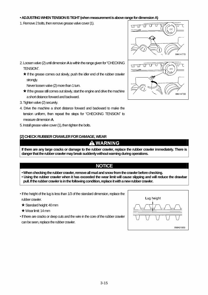
3-15
• ADJUSTING WHEN TENSION IS TIGHT (when measurement is above range for dimension A)
1. Remove 2 bolts, then remove grease valve cover (1).
2. Loosen valve (2) until dimension A is within the range given for “CHECKING
TENSION”.
If the grease comes out slowly, push the idler end of the rubber crawler
strongly.
Never loosen valve (2) more than 1 turn.
If the grease still comes out slowly, start the engine and drive the machine
a short distance forward and backward.
3. Tighten valve (2) securely.
4. Drive the machine a short distance forward and backward to make the
tension uniform, then repeat the steps for “CHECKING TENSION” to
measure dimension A.
5. Install grease valve cover (1), then tighten the bolts.
[2] CHECK RUBBER CRAWLER FOR DAMAGE, WEAR
If there are any large cracks or damage to the rubber crawler, replace the rubber crawler immediately. There is danger that the rubber crawler may break suddenly without warning during operations.
NOTICE
• When checking the rubber crawler, remove all mud and snow from the crawler before checking. • Using the rubber crawler when it has exceeded the wear limit will cause slipping and will reduce the drawbar pull. If the rubber crawler is in the following condition, replace it with a new rubber crawler.
• If the height of the lug is less than 1/3 of the standard dimension, replace the
rubber crawler.
Standard height: 40 mm
Wear limit: 14 mm
• If there are cracks or deep cuts and the wire in the core of the rubber crawler
can be seen, replace the rubber crawler.

3-16
[3] CLEAN, REPLACE AIR CLEANER
Applicable to external mounting type
• Never clean, or replace the air cleaner when the engine is running. • When using compressed air to clean the element, there is danger that dirt and dust may fly and get into eyes. Always wear safety glasses.
NOTICE
• When cleaning the outer element, do not hit it or knock it against other objects. • Do not use the outer element if the folds or seal are damaged. • Replace the outer element with a new part if it has been cleaned three or four times, or if it has been used for one year. When replacing the outer element, replace the inner element at the same time.
• After cleaning the outer element, if the engine exhaust gas color is black or there is lack of power, replace the outer element. When replacing the outer element, replace the inner element at the same time.
• CHECK AIR CLEANER
1. Raise the dump body. For details, see “OPERATION 4. OPERATING
DUMP BODY”.
2. If dust indicator (1) inside the air cleaner is red, clean the air cleaner element.
• METHOD OF CLEANING OUTER ELEMENT
1. Raise the dump body. For details, see “OPERATION 4. OPERATING
DUMP BODY”.
2. Loosen the air cleaner band (1), then remove the dust pan (2).
3. Remove the wing bolt (3) and take out the element (4).
4. Blow with dry compressed air (max. 0.68 MPa [7 kgf/cm2]) along the folds
from the inside of element (4).
Next, blow along the folds from the outside of the element, then blow from
the inside of the element again.

3-17
5. After cleaning, use a light bulb from inside the element to check if there are
any small holes or thin places in the element. Replace the element if such
places are found.
6. Remove the baffle (5) from the inside of the dust pan (2), then clean the
inside of the dust pan.
7. Set the element (4) in the body, then secure with the wing nut (3).
8. Assemble the buffer (5) to the dust pan (2).
9. Set the dust pan (2) to the body with the TOP mark on the bottom surface
facing up, then secure with the band (1).
• METHOD OF REPLACING ELEMENT
Follow the procedure in “METHOD OF CLEANING ELEMENT” to remove
the element, then install a new element.

3-18
[3] CLEAN, REPLACE AIR CLEANER
Applicable to operator’s cab rear mounting type (Cab Specifications)
• Never clean, or replace the air cleaner when the engine is running. • When using compressed air to clean the element, there is danger that dirt and dust may fly and get into eyes. Always wear safety glasses.
NOTICE
• When cleaning the outer element, do not hit it or knock it against other objects. • Do not use the outer element if the folds or seal are damaged. • Replace the outer element with a new part if it has been cleaned three or four times, or if it has been used for one year. When replacing the outer element, replace the inner element at the same time.
• After cleaning the outer element, if the engine exhaust gas color is black or there is lack of power, replace the outer element. When replacing the outer element, replace the inner element at the same time.
• CHECK AIR CLEANER
1. Raise the dump body. For details, see “OPERATION 4. OPERATING
DUMP BODY”.
2. Open the inspection cover (2) at the rear side of the cab, then check the air
cleaner inside the cover.
3. If dust indicator (1) inside the air cleaner is red, clean the air cleaner element.
• METHOD OF CLEANING OUTER ELEMENT
1. Open the cover (6) at the left side of the cab.
2. Loosen the air cleaner band (1), then remove the dust pan (2).

3-19
3. Remove the wing bolt (3) and take out the element (4).
4. Blow with dry compressed air (max. 0.68 MPa [7 kgf/cm2]) along the folds
from the inside of element (4).
Next, blow along the folds from the outside of the element, then blow from
the inside of the element again.
5. After cleaning, use a light bulb from inside the element to check if there are
any small holes or thin places in the element. Replace the element if such
places are found.
6. Remove the baffle (5) from the inside of the dust pan (2), then clean the
inside of the dust pan.
7. Set the element (4) in the body, then secure with the wing nut (3).
8. Assemble the buffer (5) to the dust pan (2).
9. Set the dust pan (2) to the body with the TOP mark on the bottom surface
facing up, then secure with the band (1).
10. Close the cover (6).
• METHOD OF REPLACING ELEMENT
Follow the procedure in “METHOD OF CLEANING ELEMENT” to remove
the element, then install a new element.
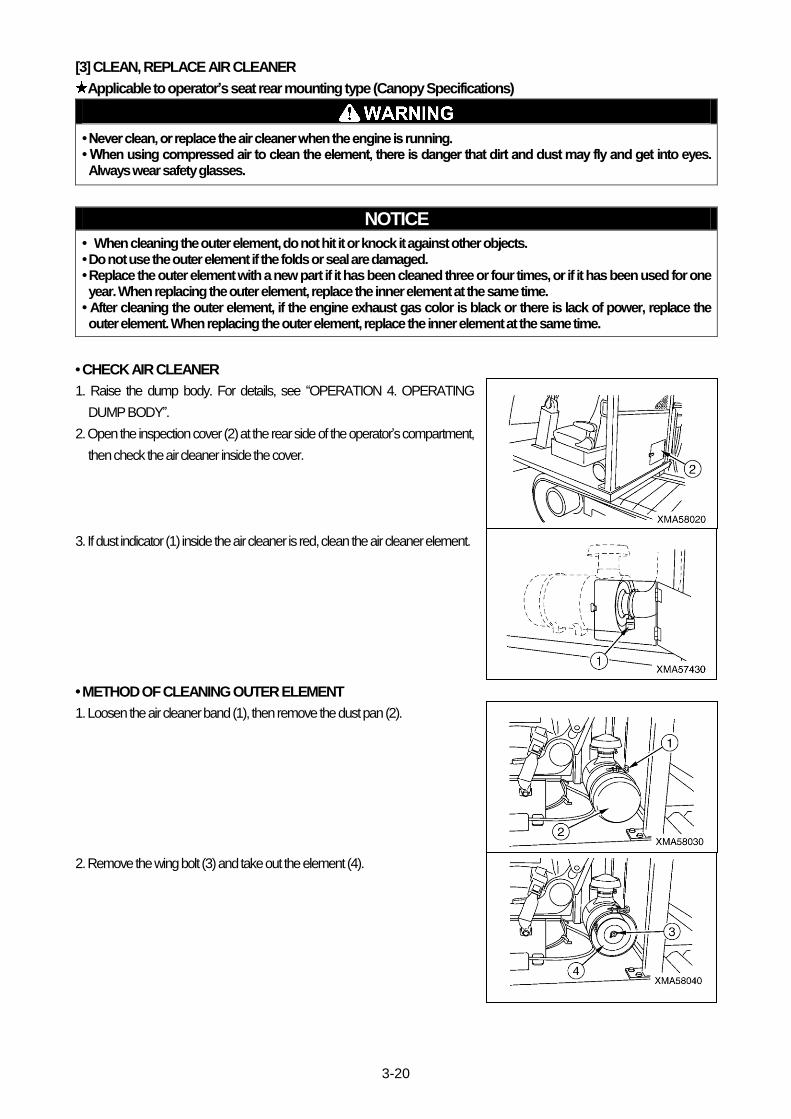
3-20
[3] CLEAN, REPLACE AIR CLEANER
Applicable to operator’s seat rear mounting type (Canopy Specifications)
• Never clean, or replace the air cleaner when the engine is running. • When using compressed air to clean the element, there is danger that dirt and dust may fly and get into eyes. Always wear safety glasses.
NOTICE
• When cleaning the outer element, do not hit it or knock it against other objects. • Do not use the outer element if the folds or seal are damaged. • Replace the outer element with a new part if it has been cleaned three or four times, or if it has been used for one year. When replacing the outer element, replace the inner element at the same time.
• After cleaning the outer element, if the engine exhaust gas color is black or there is lack of power, replace the outer element. When replacing the outer element, replace the inner element at the same time.
• CHECK AIR CLEANER
1. Raise the dump body. For details, see “OPERATION 4. OPERATING
DUMP BODY”.
2. Open the inspection cover (2) at the rear side of the operator’s compartment,
then check the air cleaner inside the cover.
3. If dust indicator (1) inside the air cleaner is red, clean the air cleaner element.
• METHOD OF CLEANING OUTER ELEMENT
1. Loosen the air cleaner band (1), then remove the dust pan (2).
2. Remove the wing bolt (3) and take out the element (4).

3-21
4. Blow with dry compressed air (max. 0.68 MPa [7 kgf/cm2]) along the folds
from the inside of element (4).
Next, blow along the folds from the outside of the element, then blow from
the inside of the element again.
5. After cleaning, use a light bulb from inside the element to check if there are
any small holes or thin places in the element. Replace the element if such
places are found.
6. Remove the baffle (5) from the inside of the dust pan (2), then clean the
inside of the dust pan.
7. Set the element (4) in the body, then secure with the wing nut (3).
8. Assemble the buffer (5) to the dust pan (2).
9. Set the dust pan (2) to the body with the TOP mark on the bottom surface
facing up, then secure with the band (1).
• METHOD OF REPLACING ELEMENT
Follow the procedure in “METHOD OF CLEANING ELEMENT” to remove
the element, then install a new element.

3-22
[4] CLEAN INSIDE OF COOLING SYSTEM AND CHANGE COOLANT
• Immediately after the engine is stopped, the coolant is at high temperature, so there is danger of burns if you drain the coolant immediately. Wait for the engine to cool down before draining the coolant.
• Do not suddenly remove the cap when the radiator water temperature is high. Boiling water will spurt out and cause burns. Wait for the water temperature to go down before removing the cap. When removing the cap, raise the lever attached to the cap to fully release the internal pressure, then remove the cap.
NOTICE
• Replace the cooling water (coolant) every year or 2000 running hours whichever comes first. • For the coolant mixture ratio of cooling water, see "Operation 8. Cold Weather Operation" in "[2] Coolant Mixture Ratio in Cooling Water ".
Clean the cooling water circuit as follows.
Use tap water for the coolant.
Do not use river water, well water, or untreated water supplies.
1. Stop the machine on level ground and stop the engine.
2. Open the engine inspection cover.
3. Raise the lever (1) attached to the radiator cap to release the internal
pressure before removing the radiator cap (2), then remove radiator cap (2).
4. Remove the undercover.
5. Drain the water from the following two places.
(1) Open the drain valve (3).
(2) Open the drain valve on the engine.
For details of the position of the drain valve on the engine, see the
separate engine operation manual.
If there is antifreeze in the coolant, put containers to catch the water under
each of the drain valves.
6. After draining the water, close the two drain valves opened in Step 5, then
add tap water through the water filler to fill the radiator.
7. Open the two drain valves in Step 5, then start the engine, run at low idling,
and run water through the system to flush it for 10 minutes.
While running water through the cooling system to flush it, be careful to
adjust the water flow so that the radiator is always full.
While running water through the cooling system to flush it, be careful that
the water supply hose does not slip out of the water filler.

3-23
8. After flushing the system, stop the engine, stop the water supply, then drain the water.
9. After draining the water, close the two drain valves in Step 5, then add cleaning agent through the water filler.
For details of the method of cleaning, see the instructions on the cleaning agent.
10. After flushing with cleaning agent, open the two drain valves in Step 5, drain the water, then start the engine, run at low idling,
and flush with water until clean water comes out.
While running water through the cooling system to flush it, be careful to adjust the water flow so that the radiator is always
full.
While running water through the cooling system to flush it, be careful that the water supply hose does not slip out of the
water filler.
11. When clean water comes out, stop the engine, and close the two drain valves in Step 5.
12. Add tap water through the water filler to fill the radiator.
13. Start the engine, run for 5 minutes at low idling, then run for a further 5 minutes at high idling to remove the air from the
coolant.
Leave the radiator cap removed when doing this.
14. Stop the engine, leave for approx. 3 minutes, then add tap water to near
the top of the water filler, and tighten the radiator cap (2).
15. Close the engine inspection cover.
16. Install the undercover.

3-24
[5] CHECK, CLEAN RADIATOR, OIL COOLER, INTER COOLER, A/C CONDENSOR FINS
• Never inspect or clean the fins when the engine is running. Always stop the engine before starting the operation. • When using compressed air to clean the fins, there is danger that dirt and dust may fly and get into eyes. Always wear safety glasses.
NOTICE
• When cleaning the fins, use compressed air at a pressure of less than 0.29Mpa {3 kgf/cm
2} , and stand away from the fins when
directing the compressed air. If the compressed air is blown directly against the radiator or is blown at high pressure, the fins will be damaged and this will cause leakage of water or oil.
• When cleaning the fins, do not use steam or water instead of compressed air. This causes clogging.
1. Remove the front grill.
2. From the front face of the front grill, check the radiator fins (1), oil cooler fins
(2) and intercooler fins (3) to see if there is any mud, dirt, dead leaves, or
paper clogging the fins.
3. If the result of the inspection shows that the fins are clogged, blow with dry
compressed air (0.29 MPa [3 kgf/cm2]) to clean.
4. After cleaning the fins, install the front grill.
[6] CHECK WINDOW WASHER FLUID LEVEL, ADD FLUID Applicable to Cab Specifications
• CHECKING, FILLING
If the window washer fluid does not come out, remove cap (2), and check the
level of the fluid in washer tank (1).
If the level is low, fill with automobile window washer fluid.
When filling with fluid, be careful not to let dirt get in.
The washer tank is installed to the outside at the rear of the cab.
• MIXING RATIO FOR WINDOW WASHER FLUID
Change the mixture ratio of the window washer fluid according to the ambient temperature.
Mix the concentrated window washer fluid with tap water according to the proportions given in the table below, then fill the
washer tank.
There are two types of concentrated window washer fluid: the general type for use at freezing temperatures of –10 deg C,
and a cold weather type for use in temperatures down to –30 deg C. Select the type according to the territory and season.
Territory, season Mixing proportion
Freezing temperature Concentrated fluid Tap water
Normal 1/3 2/3 –10°C (14°F)
Winter in cold area 1/2 1/2 -20°C (-4°F)
Winter in extremely cold area Use undiluted washer fluid None –30°C (-22°F)
Applicable to Canopy Specifications
Applicable to Cab Specifications

3-25
[7] CHECK BATTERY ELECTROLYTE LEVEL, ADD DISTILLED WATER
• If any tool touches between the battery positive (+) terminal and the chassis, there is danger that sparks will be caused. Do not put tools and other metal objects in your breast pocket. They may fall out.
• Be careful not to get battery electrolyte on yourself or on your clothes. • Do not bring any lighted cigarette or cigarette lighter close.
1. Open the battery inspection cover.
2. Look into indicator (1) of the battery.
If indicator (1) is in "blue", both the density and level of battery electrolyte
are within the normal ranges.
If indicator (1) is in "white", the battery electrolyte density drops below the
normal range.
If indicator (1) is in "red", the battery electrolyte level drops below the
normal range.
3. If indicator (1) is turned out to be "white", charge the battery.
If indicator (1) is turned out to be "red", remove all caps (2) and add distilled
water.
If indicator (1) does not turn "blue" even after adding water, charge the batt
ery.
If indicator (1) still does not turn "blue" even after the charge, replace the b
attery.
4. Close the battery inspection cover.
The battery is not a maintenance-free type. Check the battery approximately
every 100 hours.

3-26
7.5 CHECK BEFORE STARTING [1] CHECK COOLANT LEVEL, ADD WATER
Do not suddenly remove the cap when the radiator water temperature is high. Boiling water will spurt out and cause burns. Wait for the water temperature to go down before removing the cap. When removing the cap, raise the lever attached to the cap to fully release the internal pressure, then remove the cap.
NOTICE
If the result of the coolant level check shows that more water must be added than usual, there is probably a water leak, so search for the cause and repair the problem immediately.
1. Open the engine inspection cover.
2. Raise the lever (1) attached to the radiator cap to release the internal
pressure before removing the radiator cap (2), then remove radiator cap (2).
3. Check the coolant level is close to the bottom of the filler port.
If the coolant level is low, add tap water.
4. After adding water, tighten the radiator cap (2) securely.
5. Close the engine inspection cover.
[2] CHECK FUEL LEVEL, ADD FUEL
When adding fuel, never let the fuel overflow from the tank. This will cause fire.
1. Check the fuel level with level gauge (1)at the side face of the fuel tank.
2. Release the lock on the cap (2) with a key and remove the cap (2) from the
fuel tank and add fuel through the fuel filler.
3. Check the breather hole on the inside of the cap, and if it is clogged, wash it.
4. After adding fuel, tighten the cap (2) securely and lock up it with a key.
Always fill the fuel tank after completing the day’s operation.
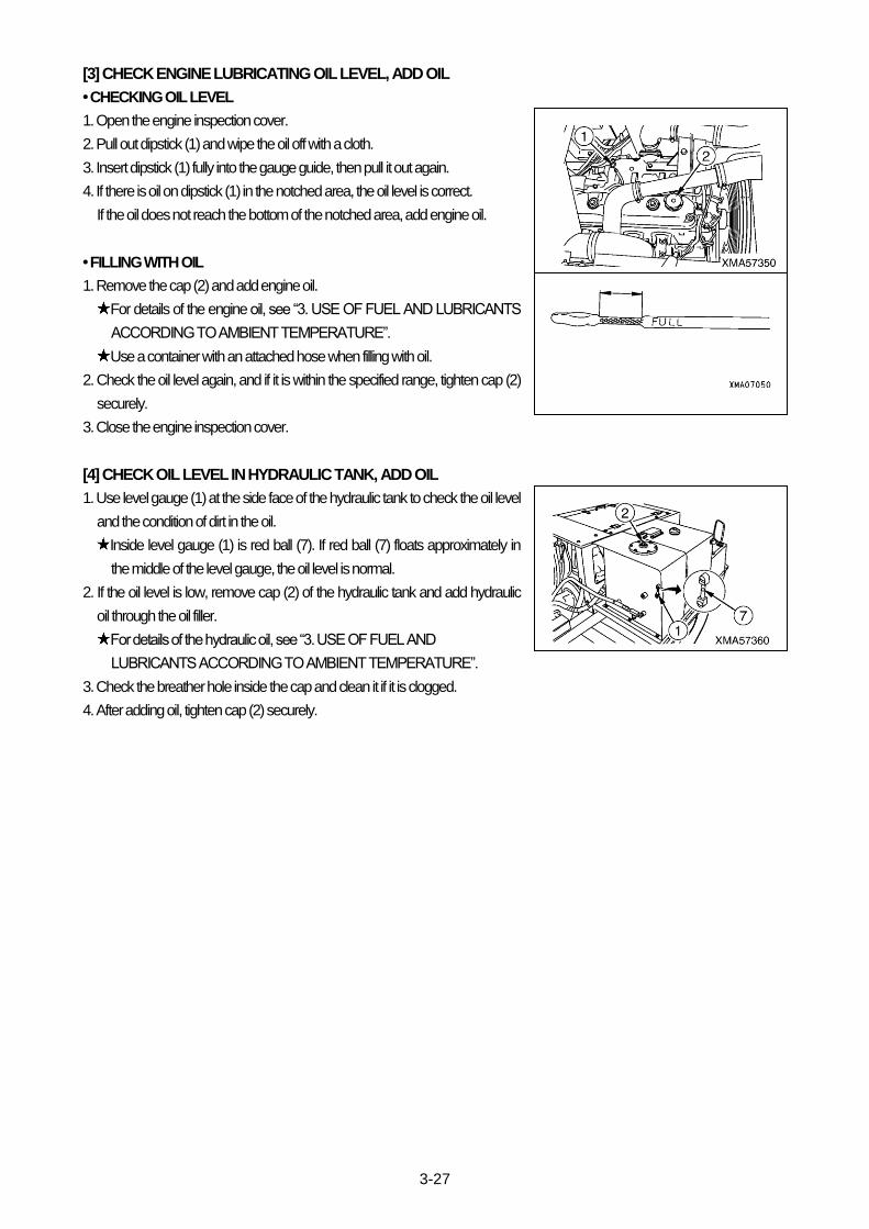
3-27
[3] CHECK ENGINE LUBRICATING OIL LEVEL, ADD OIL
• CHECKING OIL LEVEL
1. Open the engine inspection cover.
2. Pull out dipstick (1) and wipe the oil off with a cloth.
3. Insert dipstick (1) fully into the gauge guide, then pull it out again.
4. If there is oil on dipstick (1) in the notched area, the oil level is correct.
If the oil does not reach the bottom of the notched area, add engine oil.
• FILLING WITH OIL
1. Remove the cap (2) and add engine oil.
For details of the engine oil, see “3. USE OF FUEL AND LUBRICANTS
ACCORDING TO AMBIENT TEMPERATURE”.
Use a container with an attached hose when filling with oil.
2. Check the oil level again, and if it is within the specified range, tighten cap (2)
securely.
3. Close the engine inspection cover.
[4] CHECK OIL LEVEL IN HYDRAULIC TANK, ADD OIL
1. Use level gauge (1) at the side face of the hydraulic tank to check the oil level
and the condition of dirt in the oil.
Inside level gauge (1) is red ball (7). If red ball (7) floats approximately in
the middle of the level gauge, the oil level is normal.
2. If the oil level is low, remove cap (2) of the hydraulic tank and add hydraulic
oil through the oil filler.
For details of the hydraulic oil, see “3. USE OF FUEL AND
LUBRICANTS ACCORDING TO AMBIENT TEMPERATURE”.
3. Check the breather hole inside the cap and clean it if it is clogged.
4. After adding oil, tighten cap (2) securely.

3-28
[5] CHECK DUST INDICATOR
Applicable to external mounting type
1. Raise the dump body. For details, see “OPERATION 4. OPERATING
DUMP BODY”.
2. Check if the he red piston has appeared in the transparent portion of the
dust indicator (1).
If the red piston has appeared, clean or replace the element immediately.
For details of the method of cleaning the element, see “7.4 WHEN
REQUIRED”.
3. After checking, cleaning, or replacing, push the knob or dust indicator to
return the red piston to its original position.
[5] CHECK DUST INDICATOR
Applicable to operator’s cab rear mounting type (Cab Specifications)
1. Raise the dump body. For details, see “OPERATION 4. OPERATING
DUMP BODY”.
2. Open the inspection cover (2) at the rear side of the cab, then check the air
cleaner inside the cover.
3. Check if the he red piston has appeared in the transparent portion of the
dust indicator (1).
If the red piston has appeared, clean or replace the element immediately.
For details of the method of cleaning the element, see “7.4 WHEN
REQUIRED”.
4. After checking, cleaning, or replacing, push the knob or dust indicator to
return the red piston to its original position.

3-29
[5] CHECK DUST INDICATOR
Applicable to operator’s seat rear mounting type (Canopy Specifications)
1. Raise the dump body. For details, see “OPERATION 4. OPERATING
DUMP BODY”.
2. Open the inspection cover (2) at the rear side of the operator’s compartment,
then check the air cleaner inside the cover.
3. Check if the he red piston has appeared in the transparent portion of the
dust indicator (1).
If the red piston has appeared, clean or replace the element immediately.
For details of the method of cleaning the element, see “7.4 WHEN
REQUIRED”.
4. After checking, cleaning, or replacing, push the knob or dust indicator to
return the red piston to its original position.
[6] CHECK, ADJUST FAN BELT TENSION
• CHECKING TENSION
1. Open the engine inspection cover.
2. Push with your finger (approx. 58N {6kg}) at a point midway between the fan
pulley and alternator pulley.
The deflection should be approx. 10 mm.
3. If the deflection is too large, adjust the belt tension. For details, see
“ADJUSTING TENSION”.
• ADJUSTING TENSION
1. Loosen bolt (2) and lock nut (3) at the bottom of the alternator.
2. Turn adjustment bolt (4) clockwise to move the alternator to the tank end, to
adjust the belt deflection to approx. 10 mm.
3. Tighten bolt (4) at the bottom of the alternator first, and tighten lock nut (3).
4. Repeat the procedure for checking the tension to check the belt tension
again.
5. Close the engine inspection cover.

3-30
[7] CHECK ELECTRIC WIRING
If any tool touches between the battery positive (+) terminal and the chassis, there is danger that sparks will be caused. Do not put tools and other metal objects in your breast pocket. They may fall out.
• Open the battery inspection cover, and check for looseness of the battery terminal, looseness of the ground connection and
battery relay wiring, and for signs of short circuits.
• Open the engine inspection cover, and check for loose starting motor wiring and signs of short circuits.
• Open the engine inspection cover, and check loose alternator wiring and signs of short circuit.
[8] CHECK OPERATION OF SWITCHES, LAMPS, GAUGES
• Turn the starting switch to the ON position and check that the monitor lamps light up.
• Turn the starting switch to the ON position, operate the lamp switch and flasher switch (turn signal indicator) inside the
combination switch, and check that each lamp lights up.
If any lamp does not light up, the bulb is probably blown or there is a disconnection, so contact your distributor.
• Turn the starting switch to the ON position, operate the Hi-Lo speed range selector switch, and check that the high speed
travel lamp on the instrument panel lights up.
If high speed travel lamp does not light up, the bulb is probably blown or there is a disconnection, so contact your distributor.
• Turn the starting switch to the ON position, press the parking brake switch, and check that the parking lamp on the instrument
panel lights up.
If parking lamp does not light up, the bulb is probably blown or there is a disconnection, so contact your distributor.
• Turn the starting switch to the ON position, operate the wiper switch, and check that the wiper motor action.
Applicable to Cab Specifications.
If wiper motor does not acting, there is probably a failure or disconnection in the waiper motor, so contact your distributor.
• Turn the starting switch to the ON position, operate the heater switch, and check that the car heater function.
Applicable to Cab Specifications.
If car heater does not function, there is probably a failure or disconnection in the car heater, so contact your distributor.
[9] CHECK OPERATION OF HORN, ALARM BUZZER
• Turn the starting switch to the ON position, push the horn switch inside the combination switch, and check that the horn
sounds.
If the horn does not sound, there is probably a failure or disconnection in the horn, so contact your distributor.
• Turn the starting switch to the ON position, press the parking brake switch and check that the buzzer sounds.
If the parking brake buzzer does not sound, there is probably a failure or disconnection in the buzzer, so contact your
distributor.
• Turn the starting switch to the ON position, operate the travel lever to the REVERSE position and check that the backup
buzzer sounds.
If the backup buzzer does not sound, there is probably a failure or disconnection in the buzzer or backup buzzer switch, so
contact your distributor.
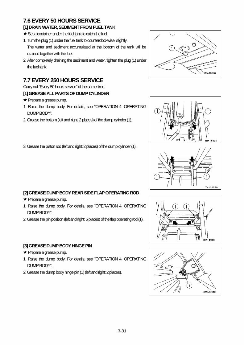
3-31
7.6 EVERY 50 HOURS SERVICE [1] DRAIN WATER, SEDIMENT FROM FUEL TANK
Set a container under the fuel tank to catch the fuel.
1. Turn the plug (1) under the fuel tank to counterclockwise slightly.
The water and sediment accumulated at the bottom of the tank will be
drained together with the fuel.
2. After completely draining the sediment and water, tighten the plug (1) under
the fuel tank.
7.7 EVERY 250 HOURS SERVICE Carry out “Every-50 hours service” at the same time.
[1] GREASE ALL PARTS OF DUMP CYLINDER
Prepare a grease pump.
1. Raise the dump body. For details, see “OPERATION 4. OPERATING
DUMP BODY”.
2. Grease the bottom (left and right: 2 places) of the dump cylinder (1).
3. Grease the piston rod (left and right: 2 places) of the dump cylinder (1).
[2] GREASE DUMP BODY REAR SIDE FLAP OPERATING ROD
Prepare a grease pump.
1. Raise the dump body. For details, see “OPERATION 4. OPERATING
DUMP BODY”.
2. Grease the pin position (left and right: 6 places) of the flap operating rod (1).
[3] GREASE DUMP BODY HINGE PIN
Prepare a grease pump.
1. Raise the dump body. For details, see “OPERATION 4. OPERATING
DUMP BODY”.
2. Grease the dump body hinge pin (1) (left and right: 2 places).

3-32
7.8 EVERY 500 HOURS SERVICE Carry out “Every-50 hours, and Every-250 hours service” at the same time.
[1] REPLACE FUEL FILTER
• Stop the engine and wait for the engine to cool down. • Do not smoke or bring any flame close.
NOTICE
After replacing the fuel filter, always bleed the air from the fuel circuit. For details, see the separate engine operation manual..
Set a container under the fuel filter to catch the fuel.
Prepare a filter wrench.
1. Open the engine inspection cover.
2. Using the filter wrench, turn the fuel filter cartridge (1) to counterclockwise
and remove it.
3. Clean the fuel filter mount, coat the packing surface of the new fuel filter
cartridge (1) with engine oil, then install it to the mount.
When installing a new fuel filter cartridge, always tighten it by hand, and
be careful not to tighten it too much.
For details, see the separate engine operation manual.
4. Close the engine inspection cover.

3-33
[2] CHANGE ENGINE LUBRICATING OIL, REPLACE ENGINE OIL FILTER
• Stop the engine and wait for the temperature to go down. • After adding oil, tighten the cap and drain plug securely, then wipe up any spilled oil.
Set a container under the engine to catch the oil.
Prepare a filter wrench.
1. Go under the machine and remove the drain plug (3) from the engine oil
pan and drain the oil.
Set the container under the engine oil pan to catch the oil.
Be careful not to get oil on yourself.
2. Check the drained oil.
If there are large amounts of metal particles or dirt in the drained oil,
please contact your distributor.
3. After completely draining the oil, tighten the drain plug (3).
4. Using the filter wrench, turn the oil filter cartridge (4) at the right side of the
engine oil pan to counterclockwise and remove it.
5. Clean the oil filter mount, coat the packing surface of the new oil filter
cartridge with engine oil, then install it to the mount.
Fill the Engine oil into the new filter cartridge.
When installing a new filter cartridge, always tighten it by hand, and be
careful not to tighten it too much.
For details, see the separate engine operation manual.
6. Open the engine inspection cover.
7. Remove the filler cap (2) and add the specified amount of engine oil.
For details of the oil to use, see “3. USE OF FUEL AND LUBRICANTS
ACCORDING TO AMBIENT TEMPERATURE”.
Engine oil refill amount: 9 liters (2.38 US gal, 1.98 UK gal)
Use a container with an attached hose when filling with oil.
8. Start the engine, run at idling for several minutes, then check that the oil is
within the range between the top and bottom marks on the engine oil level
gauge. For details, see “7.5 CHECK BEFORE STARTING”.
9. Close the engine inspection cover.

3-34
[3] REPLACE HYDRAULIC LINE FILTER
• Stop the engine and wait for the engine to cool down. • Loosen the cap of the hydraulic tank slowly to release the internal pressure completely, then remove the cap. • Operate the travel lever and dump control lever 2 or 3 times to the end of their stroke to completely release the remaining pressure in the hydraulic circuit.
NOTICE
When replacing the hydraulic line filter, always change the oil in the hydraulic tank at the same time.
Set a container under the hydraulic line filter to catch the oil.
1. Raise the dump body. For details, see “OPERATION 4. OPERATING
DUMP BODY”.
2. Remove the drain plug (3) from the line filter (1), and drain the oil.
3. Put the wrench to the nut portion (4), turn the nut portion (4) to
counterclockwise and remove the filter case (5).
4. Remove the O-rings (7), (8) inside the filter head (6).
5. Clean the line filter head (6).
6. Take out the element (9) in the filter case (5), and wash the filter case (5).
7. Fit the new O-rings (7), (8) into the filter head (6).
8. Insert a new element (9) into the filter case (5), and screw it into the filter head
(6) mounting position.
When inserting the element into the filter case, be careful not to let the
spring (10) inside the filter case collapse.
Fill the hydraulic oil to the filter case.
9. Lower the dump body. For details, see “OPERATION 4. OPERATING
DUMP BODY”.

3-35
[4] CHANGE OIL IN HYDRAULIC TANK
• Stop the engine and wait for the engine to cool down. • Loosen the oil filler cap slowly to release the pressure inside the hydraulic tank, then remove the cap. • Make full stroke operations of the travel lever and the damp control lever to release the remaining pressure inside the hydraulic circuits totally.
• After adding oil, tighten the cap and drain plug securely, then wipe up any spilled oil.
NOTICE
• When changing the oil in the hydraulic tank, always replace the hydraulic line filter at the same time. • Always replace the O-ring used inspection cover inside the hydraulic tank with a new O-ring.
Set a container under the hydraulic tank to catch the oil.
1. Remove the filler plug (2) on the hydraulic tank.
2. Turn drain plug (3) at the bottom of the hydraulic tank to counterclockwise
and drain the oil from the hydraulic tank.
Set the container under the hydraulic tank to catch the oil.
Be careful not to get oil on yourself.
3. Inspect the drained oil.
If there are large amounts of metal particles or dirt in the drained oil,
please contact your distributor.
4. After completely draining the oil, tighten drain plug (3).
5. Remove the 6 bolts, then remove the inspection cover (4).
6. Take out the oil strainer (5) inside the hydraulic tank, then wash it in diesel oil.
7. Install the oil strainer (5) inside the hydraulic tank, set new O-ring (6) to the
hydraulic tank, then install inspection cover (4) and tighten the bolts.
8. Fill with hydraulic oil through the oil filler.
For details of the hydraulic oil to use, see “3. USE OF FUEL, COOLANT,
AND LUBRICANT ACCORDING TO AMBIENT TEMPERATURE”.
Hydraulic oil refill amount: 70 liters (18.49 US gal, 15.40 UK gal)
Use a container with an attached hose when filling with oil.
9. Check that the oil level is between the top and bottom red lines on the level
gauge at the rear of the hydraulic tank. For details, see “7.5 CHECK
BEFORE STARTING [4]”.

3-36
7.9 EVERY 1500 HOURS SERVICE Carry out “Every-50 hours, Every-250 hours and Every-500 hours service” at the same time.
[1] CHANGE OIL INSIDE TRAVEL MOTOR REDUCTION GEAR CASE
• Stop the engine and wait for the oil temperature to go down. • After adding oil, tighten the plugs securely and wipe up any spilled oil.
Set a container under the travel motor reduction gear case to catch the oil.
1. Drive the machine forward or backward to position drain plug mark (1) of the
reduction gear case at the bottom, then stop the engine.
2. Remove the oil filler plug (2), oil level inspection plug (3), and drain plug (4),
and drain the oil from the case.
Set the container under the travel motor to catch the oil.
3. Inspect the drained oil.
If there are large amounts of metal particles or dirt in the drained oil,
please contact your distributor.
4. After the oil has been completely drained, tighten drain plug (4).
5. Add the specified amount of gear oil through the oil filler plug (2), and check
that oil comes out from the oil level inspection plug (3) hole.
For details of the gear oil, see “3. USE OF FUEL AND LUBRICANTS
ACCORDING TO AMBIENT TEMPERATURE”.
Specified amount of gear oil: 3.2 liters (0.84 US gal, 0.70 UK gal)
6. Tighten the oil filler plug (2) and the oil level inspection plug (3).

4-1
SPECIFICATIONS
1. DIMENSION DRAWING 4-2
2 .SPECIFICATIONS TABLE 4-3
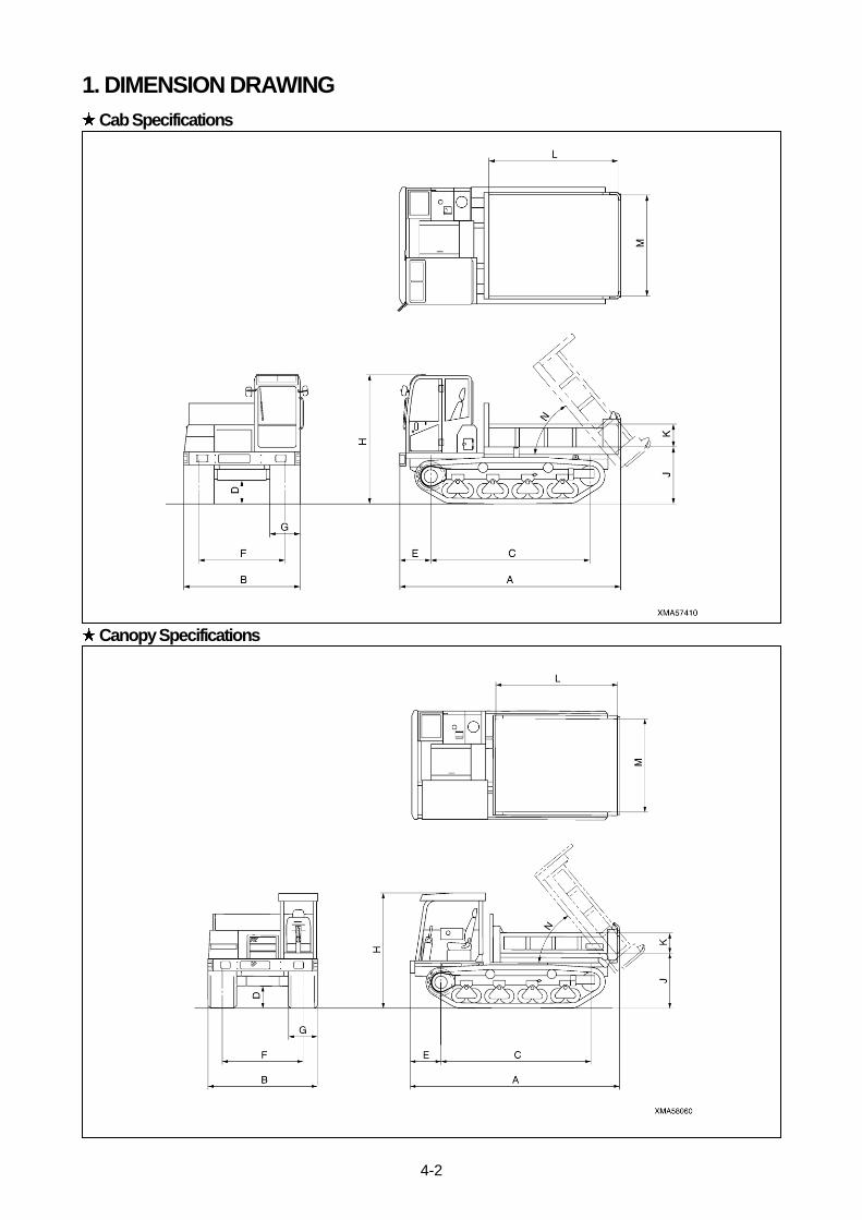
4-2
1. DIMENSION DRAWING
Cab Specifications
Canopy Specifications

4-3
2 .SPECIFICATIONS TABLE
Model name MST-800VD
Cab Specifications Canopy Specifications
A Overall length (mm) 4,430 4,430
B Overall width (mm) 2,425 2,300
C Distance between center of idler and center of sprocket
(mm) 3,130 3,130
D Min. ground clearance (mm) 470 470
E Distance between front of machine and center of sprocket
(mm) 690 690
F Track gauge (mm) 1,700 1,700
G Track width (mm) 600 600
H Overall height (mm) 2,590
(Cab roof top) 2,380
(Canopy top)
J Distance between ground and bottom of dump body
(mm) 1,160 1,160
K Dump body height (mm) 350 350
L Dump body length (mm) 2,600 2,600
M Dump body width (mm) 1,950 1,950
N Max. dumping angle (deg) 58 58
Mass (weight) of machine (kg) 6,400 6,120
Max. payload (kg) 4,300 4,300
Drive system Fully hydraulic system (HST)
Speed change system Step-less speed change
Travel speed (at high speed range) (km/h) 0 – 9.4km/h
Travel speed (at low speed range) (km/h) 0 – 6.5km/h
Ground contact pressure (unloaded) (kPa {kg・f/c㎡}) 17.1 {0.17} 15.1 {0.16}
Ground contact pressure (loaded) (kPa {kg・f/c㎡}) 28.6 {0.29} 25.6 {0.27}
Engine model Mitsubishi 4D34-TLE2A
Engine type Water-cooled, 4-cycle, in-line upright
Direct injection type, with turbocharger, air cooled inter cooler
No. of cylinders – bore x stroke (mm) 4 – 104 x 115
Piston displacement (Liter) 3.91
Rated output/engine speed (kW/min-1) 81/2,200
Max. torque/engine speed (N・m/min-1) 394/1,600
Fuel Diesel oil
Fuel consumption ratio (Liter) 130
Battery 12V, 100Ah (2 pieces)

RUBBER CRAWLER CARRIER MST-800VD
OPERATION AND MAINTENANCE MANUAL
Document No.AE10800VD2-01
First edition: January 15, 2011
Issued by Morooka Co., Ltd.
358 Shoubeisindencho, Ryugasaki,
Ibaraki 301-0034,
Japan
No part of this manual can be reproduced in any from without permission