Embed Size (px)
Citation preview
McIntosh Laboratory, Inc. 2 Chambers Street Binghamton, New York 13903-2699 Phone: 607-723-3512 FAX: 607-724-0549
Owner’s
Manual
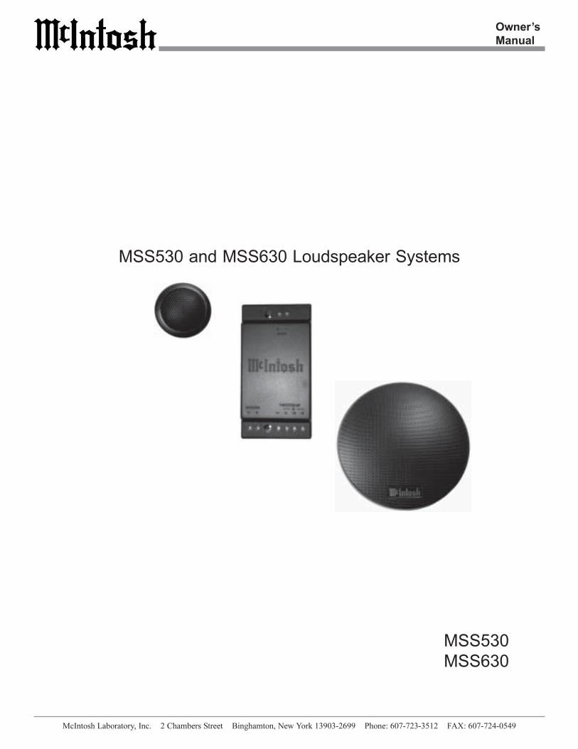
MSS530
MSS630
MSS530 and MSS630 Loudspeaker Systems
2
Table of Contents
Thank You.......................................................................... 2
Please Take a Moment ....................................................... 2
Technical Assistance .......................................................... 2
Customer Service ............................................................... 2
Table of Contents ............................................................... 2
Safety Instructions ............................................................. 3
Introduction ....................................................................... 4
Performance Features ........................................................ 4
Overall Dimensions ........................................................... 4
Installation ......................................................................... 6
How to Connect ................................................................. 8
Specifications .................................................................. 10
Packing Instructions ........................................................ 11
Customer Service
Technical Assistance
Please Take A Moment
Thank You
Copyright 2002 by McIntosh Laboratory, Inc.
The serial number, purchase date and McIntosh Dealer
name are important to you for possible insurance claim or
future service. The spaces below have been provided for
you to record that information:
Your decision to own this McIntosh MSS530 or MSS630
Loudspeaker System ranks you at the very top among dis-
criminating music listeners. You now have “The Best.” The
McIntosh dedication to “Quality,” is assurance that you
will receive many years of musical enjoyment from this
unit.
Please take a short time to read the information in this
manual. We want you to be as familiar as possible with all
the features and functions of your new McIntosh.
Serial Number:
Purchase Date:
Dealer Name:
If it is determined that your McIntosh product is in need of
repair, you can return it to your Dealer. You can also return
it to the McIntosh Laboratory Service Department. For as-
sistance on factory repair return procedure, contact the
McIntosh Service Department at:
McIntosh Laboratory, Inc.
2 Chambers Street
Binghamton, New York 13903
Phone: 607-723-3515
Fax: 607-723-1917
If at any time you have questions about your McIntosh
product, contact your McIntosh Dealer who is familiar with
your McIntosh equipment and any other brands that may
be part of your system. If you or your Dealer wish addi-
tional help concerning a suspected problem, you can re-
ceive technical assistance for all McIntosh products at:
McIntosh Laboratory, Inc.
2 Chambers Street
Binghamton, New York 13903
Phone: 607-723-3512
Fax: 607-723-3636
General Notes
1. A McIntosh MSS530 Loudspeaker System consists of a pair
of MS530 Woofer/Midranges, a pair of MS20 Tweeters and a
pair of MN530 Crossover Networks. The McIntosh MSS630
Loudspeaker System consists of a pair of MS630 Woofer/
Midranges, a pair of MS20 Tweeters and a pair of MN630
Crossover Networks.
2. Do not exceed the power handling capacity of the MSS530
or MSS630 Loudspeaker System.
3. For additional connection information, refer to the owner’s
manual(s) for any component(s) connected to the MSS530 or
MSS630 Loudspeaker Drivers and Crossover Networks.
4. The Connection Illustrations in this Owner’s Manual are
only one example of the many different possible
combinations. It is recommended that a qualified
professional assist you in the choice and installation of a
McIntosh Sound System for your vehicle.
5. The MSS530 and MSS630 Loudspeaker Systems are supplied
with Mounting Hardware. The Hardware is secured to the
inside bottom of the Shipping Carton, refer to the Packing
Illustration on page 11.
3
Safety Instructions
IMPORTANT SAFETY
INSTRUCTIONS!
PLEASE READ THEM BEFORE
OPERATING THIS EQUIPMENT.
General:
1. Read all the safety and operating instructions, con-
tained in this owner’s manual, before operating this
equipment.
2. Retain this owner’s manual for future reference about
safety and operating instructions.
3. Adhere to all warnings and operating instructions.
4. Follow all operating and use instructions.
5. Warning: To reduce risk of fire or electrical shock,
do not expose this equipment to rain or moisture.
This unit is capable of producing high sound
pressure levels. Continued exposure to high sound
pressure levels can cause permanent hearing
impairment or loss. User caution is advised and
ear protection is recommended when playing at
high volumes.
Installation:
6. Do not attempt to install the unit yourself. Please
have an authorized dealer install the unit for you.
7. Locate the equipment away from heat sources such as
heater ducts.
8. Mount the equipment only as described in this
owner’s manual.
Connection:
9. Connect this equipment only to the type of power
amplifier as described in this owner’s manual.
10. Route cords so that they are not likely to be pinched
by items placed upon or against them, paying particu-
lar attention to the point where they exit from the
instrument.
Care of Equipment:
11. Clean the instrument by dusting with a dry cloth.
12. Do not permit objects of any kind to be pushed into
and/or fall into the equipment through enclosure
openings. Never spill liquids into the equipment
through enclosure openings.
Repair of Equipment:
13. Refer servicing to a qualified service personnel under
the following conditions:
A. The cords or the connectors have been damaged.
B. Objects have fallen onto, or liquid has been
spilled into the equipment.
C. The equipment has been exposed to rain or water.
D. The equipment does not operate normally by
following the operating instructions contained
within this owner’s manual.
E. The equipment has been dropped or damaged in
any way.
F. The equipment exhibits a distinct change in
performance - this indicates a need for service.
14. When replacement parts are required, be sure the
service technician has used replacement parts speci-
fied by McIntosh or have the same characteristics as
the original part. Unauthorized substitutions may
result in fire, electric shock, or other hazards.
15. Upon completion of any service or repairs to this
product, ask the service technician to perform safety
checks to determine that the product is in proper
operating condition.
4
Performance Features
Introduction
••••• Patented Technology
The widely acclaimed McIntosh LD/HP® (Low Distortion/
High Performance) Magnetic Circuit Design1 dramatically
reduces harmonic distortion.
••••• Special Woofer/Midrange Driver Design
The Woofer/Midrange Driver utilizes injection molded
Black Polypropylene Cones and NBR Rubber Surrounds to
provide stable performance in the demanding vehicle envi-
ronment. Its Die Cast Aluminum Frame ensures excellent
rigidity, dimensional integrity and lasting value.
••••• Special Tweeter Driver Design
The Tweeter Driver utilizes a black, Soft Textile Dome for
smooth response and greater sensitivity. It also incorporates
a Neodymium Magnet which has the highest flux energy
that is currently available. The Tweeter Design utilizes both
Tinsel Voice Coil Leads and Magnetic Fluid for improved
repetitive high peak power handling capability. Pre-at-
tached leads simplify connection to the Crossover Net-
work.
••••• Low Distortion Crossover
The Crossover utilizes capacitors with low ESR, coils with
low DCR and a 2nd Order Crossover Circuit Design for
smooth frequency response. The Crossover allows for three
different high frequency response curves to compensate for
various automotive environments. It incorporates a self re-
setting Poly-Switch to provide automatic overload protec-
tion to the Loudspeaker System. The Crossover Enclosures
are made from a high temperature ABS material capable of
withstanding the demanding temperature variations of a
vehicle environment.
1Patent Number 5,151,943
The McIntosh Woofer/Midrange and Tweeter Drivers offer
extremely smooth frequency response, low distortion, high
sensitivity and high power handling capability. When these
Drivers are combined with other McIntosh Vehicle Compo-
nents, you will enjoy sonically accurate music reproduction
in your vehicle which meets McIntosh traditional standards
of excellence.
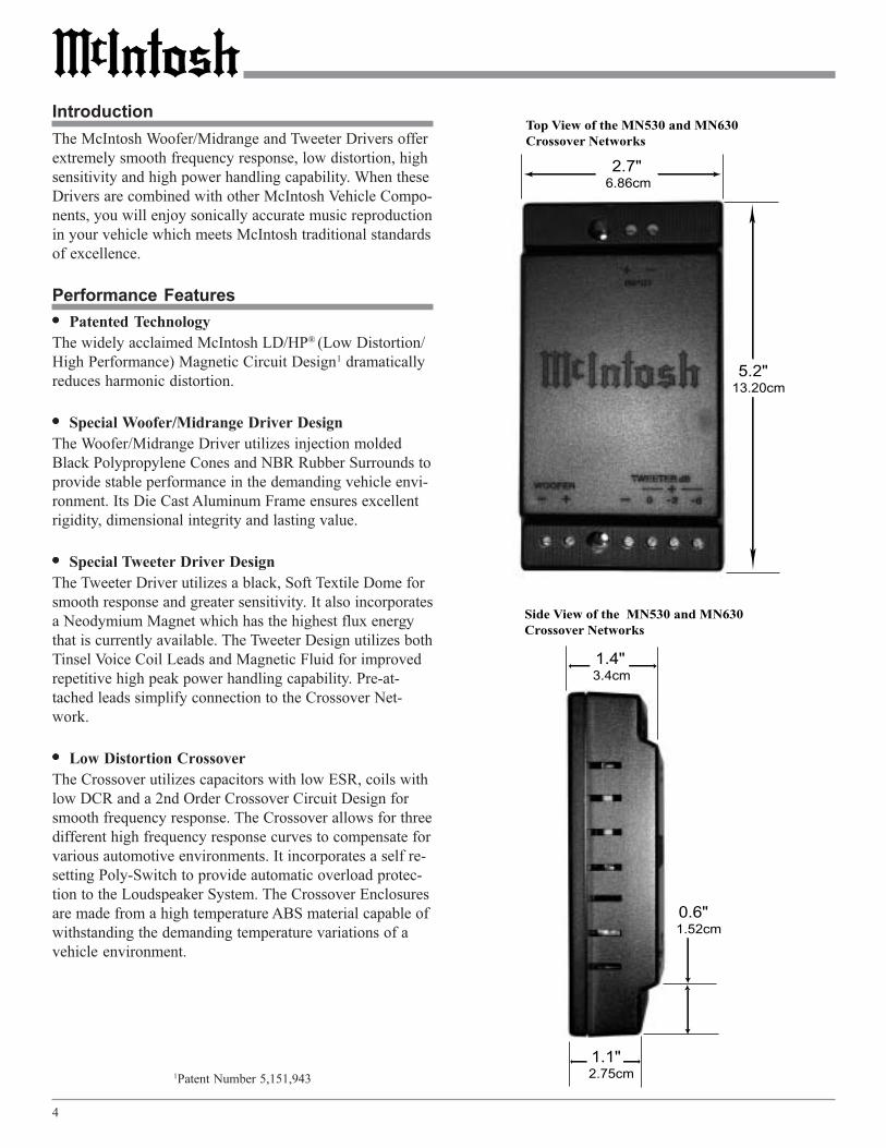
Top View of the MN530 and MN630Crossover Networks
Side View of the MN530 and MN630Crossover Networks
2.7" 6.86cm
5.2" 13.20cm
1.4" 3.4cm
1.1" 2.75cm
0.6" 1.52cm

5
Introduction, Performance Features and Overall Dimensions
5.4" 13.59cm 6.1"
15.49cm
Front View of the MS20 Tweeter Driver Side View of the MS20 Tweeter Driver Rear View of the MS20 Tweeter Driver
Front Viewof the MS530Woofer/MidrangeDriver
Side Viewof the MS530Woofer/MidrangeDriver
Side Viewof the MS630Woofer/MidrangeDriver
2.13" 5.4cm
0.88" 2.24cm
Front Viewof the MS630Woofer/MidrangeDriver
6.3" 15.9cm 7.2"
18.21cm
2.9" 7.37cm
3.25" 8.26cm
1.8" 4.55cm
6
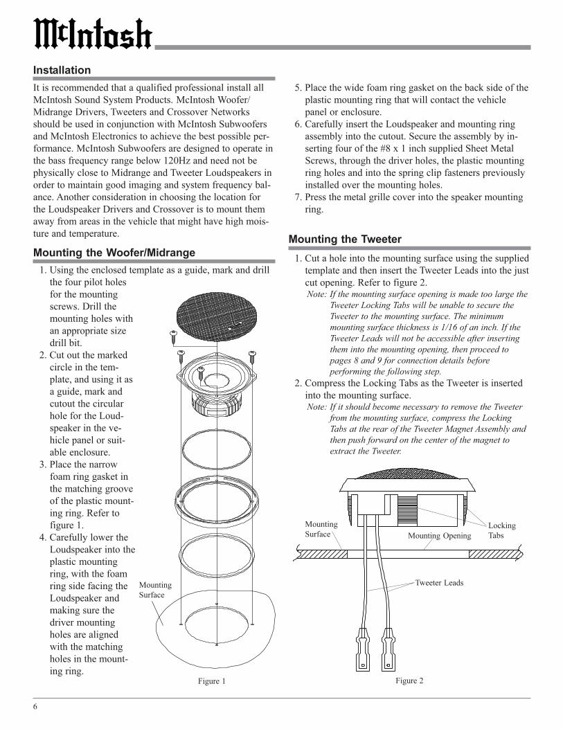
Installation
Mounting the Tweeter
1. Using the enclosed template as a guide, mark and drill
the four pilot holes
for the mounting
screws. Drill the
mounting holes with
an appropriate size
drill bit.
2. Cut out the marked
circle in the tem-
plate, and using it as
a guide, mark and
cutout the circular
hole for the Loud-
speaker in the ve-
hicle panel or suit-
able enclosure.
3. Place the narrow
foam ring gasket in
the matching groove
of the plastic mount-
ing ring. Refer to
figure 1.
4. Carefully lower the
Loudspeaker into the
plastic mounting
ring, with the foam
ring side facing the
Loudspeaker and
making sure the
driver mounting
holes are aligned
with the matching
holes in the mount-
ing ring.
Mounting the Woofer/Midrange
It is recommended that a qualified professional install all
McIntosh Sound System Products. McIntosh Woofer/
Midrange Drivers, Tweeters and Crossover Networks
should be used in conjunction with McIntosh Subwoofers
and McIntosh Electronics to achieve the best possible per-
formance. McIntosh Subwoofers are designed to operate in
the bass frequency range below 120Hz and need not be
physically close to Midrange and Tweeter Loudspeakers in
order to maintain good imaging and system frequency bal-
ance. Another consideration in choosing the location for
the Loudspeaker Drivers and Crossover is to mount them
away from areas in the vehicle that might have high mois-
ture and temperature.
1. Cut a hole into the mounting surface using the supplied
template and then insert the Tweeter Leads into the just
cut opening. Refer to figure 2.Note: If the mounting surface opening is made too large the
Tweeter Locking Tabs will be unable to secure the
Tweeter to the mounting surface. The minimum
mounting surface thickness is 1/16 of an inch. If the
Tweeter Leads will not be accessible after inserting
them into the mounting opening, then proceed to
pages 8 and 9 for connection details before
performing the following step.
2. Compress the Locking Tabs as the Tweeter is inserted
into the mounting surface.Note: If it should become necessary to remove the Tweeter
from the mounting surface, compress the Locking
Tabs at the rear of the Tweeter Magnet Assembly and
then push forward on the center of the magnet to
extract the Tweeter.
Figure 1
Mounting
Surface
5. Place the wide foam ring gasket on the back side of the
plastic mounting ring that will contact the vehicle
panel or enclosure.
6. Carefully insert the Loudspeaker and mounting ring
assembly into the cutout. Secure the assembly by in-
serting four of the #8 x 1 inch supplied Sheet Metal
Screws, through the driver holes, the plastic mounting
ring holes and into the spring clip fasteners previously
installed over the mounting holes.
7. Press the metal grille cover into the speaker mounting
ring.
Figure 2
Mounting
SurfaceLocking
Tabs
Tweeter Leads
Mounting Opening
7
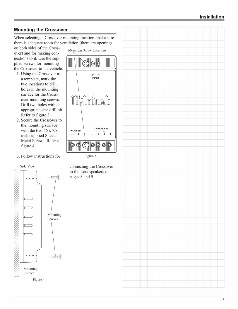
Installation
When selecting a Crossover mounting location, make sure
there is adequate room for ventilation (there are openings
on both sides of the Cross-
over) and for making con-
nections to it. Use the sup-
plied screws for mounting
the Crossover to the vehicle.
1. Using the Crossover as
a template, mark the
two locations to drill
holes in the mounting
surface for the Cross-
over mounting screws.
Drill two holes with an
appropriate size drill bit.
Refer to figure 3.
2. Secure the Crossover to
the mounting surface
with the two #6 x 7/8
inch supplied Sheet
Metal Screws. Refer to
figure 4.
3. Follow instructions for
connecting the Crossover
to the Loudspeakers on
pages 8 and 9.
Mounting the Crossover
123412341234123412341234123412341234123412341234123412341234123412341234123412341234123412341234123412341234123412341234123412341234123412341234123412341234123412341234123412341234123412341234123412341234123412341234
Figure 4
Mounting
Surface
Side View
○ ○ ○ ○ ○ ○
○ ○ ○ ○ ○ ○
Mounting
Screws
Figure 3
Mounting Screw Locations
8
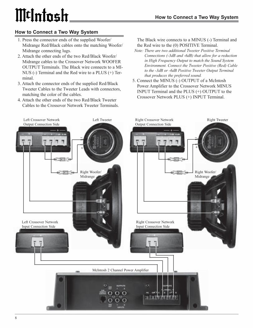
Left Crossover Network
Input Connection Side
How to Connect a Two Way System
How to Connect a Two Way System
Right Woofer/
Midrange
Right Tweeter
1. Press the connector ends of the supplied Woofer/
Midrange Red/Black cables onto the matching Woofer/
Midrange connecting lugs.
2. Attach the other ends of the two Red/Black Woofer/
Midrange cables to the Crossover Network WOOFER
OUTPUT Terminals. The Black wire connects to a MI-
NUS (-) Terminal and the Red wire to a PLUS (+) Ter-
minal.
3. Attach the connector ends of the supplied Red/Black
Tweeter Cables to the Tweeter Leads with connectors,
matching the color of the cables.
4. Attach the other ends of the two Red/Black Tweeter
Cables to the Crossover Network Tweeter Terminals.
The Black wire connects to a MINUS (-) Terminal and
the Red wire to the (0) POSITIVE Terminal.Note: There are two additional Tweeter Positive Terminal
Connections (-3dB and -6dB) that allow for a reduction
in High Frequency Output to match the Sound System
Environment. Connect the Tweeter Positive (Red) Cable
to the -3dB or -6dB Positive Tweeter Output Terminal
that produces the preferred sound.
5. Connect the MINUS (-) OUTPUT of a McIntosh
Power Amplifier to the Crossover Network MINUS
INPUT Terminal and the PLUS (+) OUTPUT to the
Crossover Network PLUS (+) INPUT Terminal.
McIntosh 2 Channel Power Amplifier
Left Crossover Network
Output Connection Side
Right Crossover Network
Input Connection Side
Right Crossover Network
Output Connection Side
+
_
+
_
+_ _
+_
+__ _
+
Left Tweeter
+
_
Right Woofer/
Midrange
+
_
0 - 3 dB -6 dB
+ 0 - 3 dB -6 dB
+
9
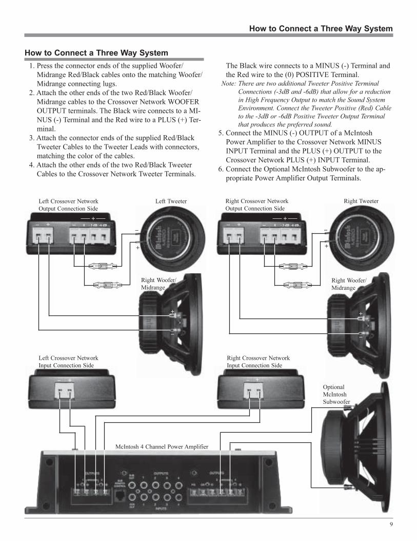
McIntosh 4 Channel Power Amplifier
How to Connect a Three Way System
How to Connect a Three Way System
Left Crossover Network
Input Connection Side
Right Woofer/
Midrange
Right TweeterLeft Crossover Network
Output Connection Side
Right Crossover Network
Input Connection Side
Right Crossover Network
Output Connection Side
+
_
+
_
+_ _
+_
+__ _
+
Left Tweeter
+
_
Right Woofer/
Midrange
+
_
Optional
McIntosh
Subwoofer
1. Press the connector ends of the supplied Woofer/
Midrange Red/Black cables onto the matching Woofer/
Midrange connecting lugs.
2. Attach the other ends of the two Red/Black Woofer/
Midrange cables to the Crossover Network WOOFER
OUTPUT terminals. The Black wire connects to a MI-
NUS (-) Terminal and the Red wire to a PLUS (+) Ter-
minal.
3. Attach the connector ends of the supplied Red/Black
Tweeter Cables to the Tweeter Leads with connectors,
matching the color of the cables.
4. Attach the other ends of the two Red/Black Tweeter
Cables to the Crossover Network Tweeter Terminals.
The Black wire connects to a MINUS (-) Terminal and
the Red wire to the (0) POSITIVE Terminal.Note: There are two additional Tweeter Positive Terminal
Connections (-3dB and -6dB) that allow for a reduction
in High Frequency Output to match the Sound System
Environment. Connect the Tweeter Positive (Red) Cable
to the -3dB or -6dB Positive Tweeter Output Terminal
that produces the preferred sound.
5. Connect the MINUS (-) OUTPUT of a McIntosh
Power Amplifier to the Crossover Network MINUS
INPUT Terminal and the PLUS (+) OUTPUT to the
Crossover Network PLUS (+) INPUT Terminal.
6. Connect the Optional McIntosh Subwoofer to the ap-
propriate Power Amplifier Output Terminals.
0 - 3 dB -6 dB
+ 0 - 3 dB -6 dB
+

10
Specifications
MSS630 System Specifications
System Parameters
Peak Power 120 Watts
Continuous Power (EIA + H.P.) 60 Watts
Frequency Response 80 Hz - 20kHz
System Sensitivity1 85 dB
Nominal Impedance (Znom) 4 Ohms
Crossover Frequency 2400 Hz
Low Pass Slope 12 db/oct
High Pass Slope 12 db/oct
MS530 Woofer/Midrange
Mounting Dimensions
Grille Overall (Diameter) 6-9/16” (166.7mm)
Speaker + Grille Overall Depth 3-7/16” (87.3mm)
Speaker Mounting Depth 2-3/4”(70mm)
Mounting Hole Diameter 4-3/4”(121mm)
MS20 Tweeter
Mounting Dimensions
Housing Overall (Diameter) 2-1/8” (54mm)
Speaker + Grille Overall Depth 7/8” (22.2mm)
Speaker Mounting Depth 9/16”(14.2mm)
Mounting Hole Diameter 1-3/4”(44.5mm)
MN530 Crossover
Mounting Dimensions
Width 2.7” (6.86mm)
Height 5.2” (13.20mm)
Depth 1.4”(3.4mm)
MSS530 System Weight
In Shipping Carton (pair) 8.6 lbs.(3.9kg)
1 The System Sensitivity includes the Woofer/Midrange Driver,
Tweeter Driver and Crossover Network.
MSS530 System Specifications
System Parameters
Peak Power 120 Watts
Continuous Power (EIA + H.P.) 60 Watts
Frequency Response 80 Hz - 20kHz
System Sensitivity1 85 dB
Nominal Impedance (Znom) 4 Ohms
Crossover Frequency 2500 Hz
Low Pass Slope 12 db/oct
High Pass Slope 12 db/oct
MS630Woofer/Midrange
Mounting Dimensions
Grille Overall (Diameter) 7-5/8” (194mm)
Speaker + Grille Overall Depth 3-15/16” (100mm)
Speaker Mounting Depth 3”(76mm)
Mounting Hole Diameter 5-7/8”(149mm)
MS20Tweeter
Mounting Dimensions
Housing Overall (Diameter) 2-1/8” (54mm)
Speaker + Grille Overall Depth 7/8” (22.2mm)
Speaker Mounting Depth 9/16”(14.2mm)
Mounting Hole Diameter 1-3/4”(44.5mm)
MN630 Crossover
Mounting Dimensions
Width 2.7” (6.86mm)
Height 5.2” (13.20mm)
Depth 1.4”(3.4mm)
MSS630 System Weight
In Shipping Carton (pair) 9.5 lbs.(4.3kg)
1 The System Sensitivity includes the Woofer/Midrange Driver,
Tweeter Driver and Crossover Network.
11
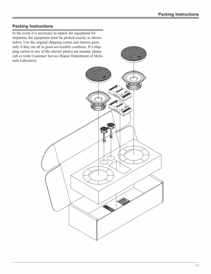
Packing Instructions
Packing Instructions
In the event it is necessary to repack the equipment for
shipment, the equipment must be packed exactly as shown
below. Use the original shipping carton and interior parts
only if they are all in good serviceable condition. If a ship-
ping carton or any of the interior part(s) are needed, please
call or write Customer Service Repair Department of McIn-
tosh Laboratory.

McIntosh Part No. 040826
McIntosh Laboratory, Inc.
2 Chambers Street
Binghamton, NY 13903