Embed Size (px)
Citation preview
Application ReportSLAA578–April 2013
MSP430FW42x ScanIF Demo Box Hardware and SoftwareDescription
Zack Mak ........................................................................................................ Smart Grid Applications
ABSTRACT
This application report describes the specific information of the demo box that detects the disc rotationusing Scan Interface in MSP430FW42x. Both hardware and software are covered to help the developerunderstand the working principle of this demo box in a short time.
This document is based on Rotation Detection With the MSP430 Scan Interface (SLAA222). Detailedtechnical information can be found in that document.
Contents1 The Demo Box .............................................................................................................. 22 Demo Source Code ......................................................................................................... 33 References ................................................................................................................. 12Appendix A Schematic ......................................................................................................... 13
List of Figures
1 Demo Box .................................................................................................................... 2
2 The LCD...................................................................................................................... 3
3 Graphical Illustration for the Criteria of Updating SIFCNT1 ........................................................... 6
4 Relationship Between the Excitation Level, the DAC Level and SIFxOUT.......................................... 8
5 Value of SIFxOUT at the Same Excitation Level With Different DAC Value........................................ 8
6 Startup Calibration Flowchart.............................................................................................. 9
7 Coarse to Fine Calibration for System Startup ........................................................................ 10
8 Relationship Between Different Parameters ........................................................................... 11
9 Example of Run Time Calibration When Excitation Level Became Higher ........................................ 12
10 Simplified Schematic of the Demo Box................................................................................. 13
List of Tables
1 Pin Connection .............................................................................................................. 3
2 ScanIF Initialization ......................................................................................................... 3
3 TSM Setup ................................................................................................................... 5
4 State Table Setting of the Demo Source Code ......................................................................... 7
All trademarks are the property of their respective owners.
1SLAA578–April 2013 MSP430FW42x ScanIF Demo Box Hardware and Software DescriptionSubmit Documentation Feedback
Copyright © 2013, Texas Instruments Incorporated

LCD displaycounter
Resister ladderfor LCD
Resister ladderfor LCD
Target boardMSP-TS430PM64
External jumperfor current
measurement
LC sensorPCB
LC sensorsunderneathLC sensorsunderneath
Rotatingdisc
The Demo Box www.ti.com
1 The Demo Box
Figure 1 shows different parts of the demo box. The target demo board is equipped with anMSP430FW429 for ScanIF operation.
Figure 1. Demo Box
NOTE:• To power the board, short the external jumper or connect the JTAG to the FET tool.• To measure the current consumption (using battery power), connect the external jumper
pin to a multi-meter.• The JTAG and the battery share the same VCC. Do not power the board using the JTAG
and the battery at the same time.• For the demo source code once the board is powered up, the LCD shows “CAL” for
initialization. If there is nothing shown on the LCD, there may be some bad contactsbetween the MCU and the target board. Opening and closing the cover of the MCUsocket should solve the problem.
• The LCD takes roughly 3 µA. Disconnect the LCD resister ladder to eliminate thatcurrent consumption. Of course, the LCD will not display numbers anymore.
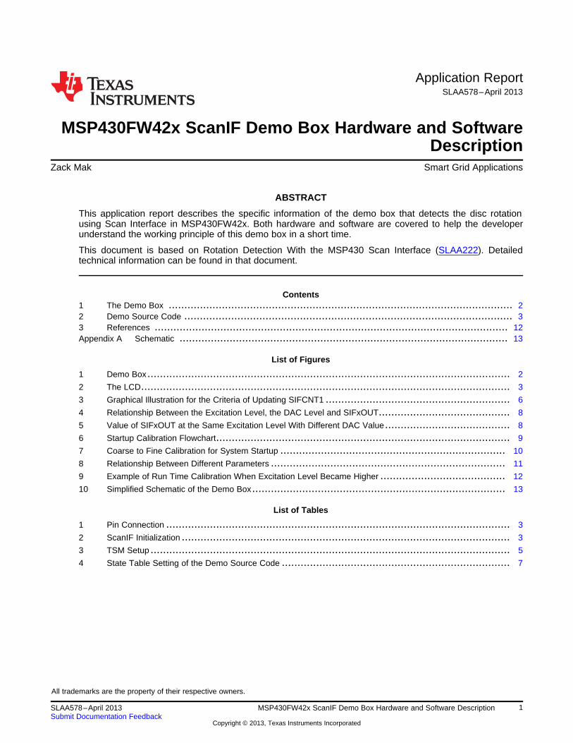
1.1 LCD
The LCD layout is shown in Figure 2. Only the 3 digits on the left (A1, A2 and A3) are used and only thecorresponding pins are connected to the MCU.
2 MSP430FW42x ScanIF Demo Box Hardware and Software Description SLAA578–April 2013Submit Documentation Feedback
Copyright © 2013, Texas Instruments Incorporated

R TX RXPM
5.00
5.004.0
92.5
9
1 22
2344
8.6
0
6.0
2
0.5
4
5.0°
0.13
3.82
0.7
7
5.0° 0.19
5.460.77
0.7
7
(1
(2
) 1
) 2ANT
PIN 1 2 3 4 5 6 7 8 9 10 11 12 13 14 15 16 17 18 19 20 21 22
COM0 A1M A1D AIDP A1P A2M A2D A2DP A2P A3M A3D A3DP A3P A4M A4D A4DP A4P A5M A5D A5DP A5P A6M A6D
COM1 A1G A1C A1N A1K A2G A2C A2N A2K A3G A3C A3N A3K A4G A4C A4N A4K A5G A5C A5N A5K A6G A6C
COM2 A1F A1B NEG A1J A2F A2B A2C0L A2J A3F A3B ANT A3J A4F A4B A4C0L A4J A5F A6B DEG A5J A6F A6B
COM3 A1E A1A A1Q A1B A2E A2A A2Q A2H A3E A3A A3Q A3H A4E A4A A4Q A4H A5E A5A A5Q A5H A6E A6A
PIN 23 24 25 26 27 28 29 30 31 32 33 34 35 36 37 38 39 40 41 42 43 44
COM0 RX A6P C0M0 BATT [] D4D D4DP D3D D3DP D2D D2DP D1D DC0L DNEG U PN PNE ) 2 TMR2
COM1 A6N A6K C0M1 B2 B1 D4C D4G D3C D3G D2C D2G D1C D1G REC R PE PSE ) 1 TMR1
COM2 TX A6J C0M2 B4 B3 D4B D4F D3B D3F D2B D2F D1B D1F PM D PS PSW (2 HRT
COM3 A6Q A6H C0M3 B6 B5 D4A D4E D3A D3E D2A D2E D1A D1E ALM L PW PNW (1 !
www.ti.com Demo Source Code
Figure 2. The LCD
Table 1. Pin Connection
LCD 1 2 5 6 9 10 25 26 27 28
MSP430F S6 S7 S8 S9 S10 S11 COM3 COM2 COM1 COM0W42x
2 Demo Source Code
The source code is divided into 3 files: lcd.c, main.c and scanif.c. This section focuses on the operation ofrotation detection using ScanIF only.
2.1 ScanIF Initialization
The initialization code is modified from Rotation Detection With the MSP430 Scan Interface (SLAA222).The main difference is that the demo source code adds test cycle settings for calibration. The setting isshown in Table 2. Some unrelated parameters are not shown.
Table 2. ScanIF Initialization
Register Setting Bitwise Value Meaning
SIFCTL2 = 0x0150; SIFDACON = 0 DAC is controlled by TSM
SIFCAON = 0 Comparator is controlled by TSM
SIFCAINV = 0 Comparator output is non-inverted
SIFCAX = 0 Comparator input from SIFCHx
SIFVSS = 0 Sample capacitor is grounded to SIFVss
SIFVCC2 = 1 AVcc/2 on
SIFSH = 0 Sample and hold disabled
SIFEN = 1 Excitation circuitry is enabled
SIFTCH1x = 01 Test channel 1 is mapped to SIFCH1
SIFTCH0x = 00 Test channel 0 is mapped to SIFCH0
3SLAA578–April 2013 MSP430FW42x ScanIF Demo Box Hardware and Software DescriptionSubmit Documentation Feedback
Copyright © 2013, Texas Instruments Incorporated

Demo Source Code www.ti.com
Table 2. ScanIF Initialization (continued)
Register Setting Bitwise Value Meaning
SIFCTL3 = 0x4000; SIFS2x = 01 SIF1OUT is the S2 source
SIFS1x = 00 SIF0OUT is the S1 source
SIFIS1x = 00 SIFIFG3 is set with each count, up or down, of SIFCNT1
SIFCTL4 = 0x33D0; SIFCNT1ENM = 1 SIFCNT1 decrement is enabled
SIFCNT1ENP = 1 SIFCNT1 increment is enabled
SIFQ7EN = 0 Q7 is not used to determine next PSM state
SIFQ6EN = 0 Q6 is not used to determine next PSM state
SIFDIV3Bx = 111 TSM restart after 330 ACLK cycle. At 32768Hz, that would be0.01sec. This reflects the sampling rate of the LC sensor.SIFDIV3Ax = 101
SIFCTL5 = 0x0045; SIFTSMRP = 0 Each TSM sequence is triggered by ACLK divider
SIFCLKFQx = 1000 Internal oscillator frequency = Nominal
SIFFNOM = 1 Internal oscillator frequency = 1MHz
SIFCLKEN = 1 TSM high frequency clock source = internal oscillator
4 MSP430FW42x ScanIF Demo Box Hardware and Software Description SLAA578–April 2013Submit Documentation Feedback
Copyright © 2013, Texas Instruments Incorporated

www.ti.com Demo Source Code
2.2 TSM Setup
The SIFTSMx is modified from the Rotation Detection With the MSP430 Scan Interface (SLAA222) sourcecode for calibration. The setting is shown in Table 3.
Table 3. TSM Setup
SIFTSM0 = 0x8800 All off. Idle for 18xSMCLK
(SIFTSM1 – 4: settings for SIFCH0) SIFCHx = 00
SIFTESTS1 = 0 (Test cycle uses SIFDACR6 for DAC)
SIFLCEN = 1 (LC enabled)
SIFCLKON = 1 (Hi-Freq clock on)
SIFTSM1 = 0x002C LC excitation for 1xSIFCLK
SIFEX = 1 (Excitation)
SIFTSM2 = 0x0424 Wait for 1xACLK
SIFACLK = 1 (use ACLK)
SIFTSM3 = 0x6934 Enable AFE for 14xSIFCLK
SIFREPEATx = 13
SIFDAC = 1 (DAC on)
SIFCA = 1 (Comparator on)
SIFTSM4 = 0x2174 Measurement for 5xSIFCLK
SIFREPEATx = 4
SIFDAC = 1
SIFRSON = 1 (Enable output latch) SIFCA = 1
(SIFTSM5 – 8: settings for SIFCH1) SIFCHx = 01
SIFTESTS1 = 1 (Test cycle uses SIFDACR7 for DAC)
SIFLCEN = 1 (LC enabled)
SIFCLKON = 1 (Hi-Freq clock on)
SIFTSM5 = 0x00AD LC excitation for 1xSIFCLK
SIFEX = 1 (Excitation)
SIFTSM6 = 0x04A5 Wait for 1xACLK
SIFACLK = 1 (use ACLK)
SIFTSM7 = 0x69B5 Enable AFE for 14xSIFCLK
SIFREPEATx = 13
SIFDAC = 1 (DAC on)
SIFCA = 1 (Comparator on)
SIFTSM8 = 0x21F5 Measurement for 5xSIFCLK
SIFREPEATx = 4
SIFDAC = 1
SIFRSON = 1 (Enable output latch)
SIFCA = 1
SIFTSM9 = 0x0200 SIFSTOP = 1 (End of TSM sequence)
5SLAA578–April 2013 MSP430FW42x ScanIF Demo Box Hardware and Software DescriptionSubmit Documentation Feedback
Copyright © 2013, Texas Instruments Incorporated

Suggested: +1
Suggested: –1,App note table 3: –1,
App note table 3: +1
10 00
0111
00
Demo Source Code www.ti.com
2.3 PSM Table Design
Rotation Detection With the MSP430 Scan Interface (SLAA222) points out that the 16-state table causes abouncing problem and suggested a 32-state table. However, if the 16-state table is carefully designed, thebouncing problem can be solved so that the PSM table can be kept simple.
Figure 3. Graphical Illustration for the Criteria of Updating SIFCNT1
From Figure 3, imagine the blue circle is the rotating disc for rotation measurement. The arrow on the bluecircle shows the rotating position. When that arrow is lying on any quadrates, the SCANIF gets the specificsensor state. For example, when the arrow lies on the yellow quadrate, S2 = 1 and S1 = 0. (State 10).
The arrows outside the square shows the different increment and decrement criteria based on twoimplementations: the implementation in Rotation Detection With the MSP430 Scan Interface (SLAA222)and the suggested implementation. The pointing direction of the arrows refers to the direction where thedisc is rotating and that state change updates the SIFCNT1 value. For example, suggested: + 1 meanswhen the disc rotates from state 10 to state 00, the SIFCNT1 will be +1.
It shows that in the application report implementation, the increment and the decrement of the counter isdone on different disc position. For the Quadrature Transitions for 2-Sensor Implementation table inRotation Detection With the MSP430 Scan Interface (SLAA222), if the disc rotates back and forth between00 and 01, the state change of 00->01 increases the counter by 1. But it will not decrease by 1 when thestate changes from 01 to 00. That will cause only +1 in this situation, which is the bouncing problem on16- state table stated in Rotation Detection With the MSP430 Scan Interface (SLAA222).
To solve that problem, set the increment and the decrement on the same position. In order to design thestate table, pair up the previous state and the current state, so that the increment and the decrement canbe occurred at the same position.
6 MSP430FW42x ScanIF Demo Box Hardware and Software Description SLAA578–April 2013Submit Documentation Feedback
Copyright © 2013, Texas Instruments Incorporated

www.ti.com Demo Source Code
Table 4 shows the state table setting of the demo source code.
Table 4. State Table Setting of the Demo Source Code
Look Up Previous CurrentPosition State State State Table Value Next
(Offset by LookCurrent Q2 Q1 Binary Byte Up MovingS1 S2) Q3 Q0 S1 S2 Q6 Q3 Q0 (-1) (+1) (Q6 ...Q0) Code Position Direction
NoP0 0 0 0 0 0 0 0 0 0 000 0000 0x00 P0 movement
Turn0 0 0 1 0 0 1 0 0 000 0001 0x01 P1 Right
Turn0 0 1 0 0 1 0 1 0 000 1100 0x0C P2 Left (-1)
Error0 0 1 1 1 1 1 0 0 100 1001 0x49 P3 (Opposite)
TurnP1 0 1 0 0 0 0 0 0 0 000 0000 0x00 P0 Left
No0 1 0 1 0 0 1 0 0 000 0001 0x01 P1 movement
Error0 1 1 0 1 1 0 0 0 100 1000 0x48 P2 (Opposite)
Turn0 1 1 1 0 1 1 0 0 000 1001 0x09 P3 Right
TurnP2 1 0 0 0 0 0 0 0 1 000 0010 0x02 P0 Right (+1)
Error1 0 0 1 1 0 1 0 0 100 0001 0x41 P1 (Opposite)
No1 0 1 0 0 1 0 0 0 000 1000 0x08 P2 movement
Turn1 0 1 1 0 1 1 0 0 000 1001 0x09 P3 Left
ErrorP3 1 1 0 0 1 0 0 0 0 100 0000 0x40 P0 (Opposite)
Turn1 1 0 1 0 0 1 0 0 000 0001 0x01 P1 Left
Turn1 1 1 0 0 1 0 0 0 000 1000 0x08 P2 Right
No1 1 1 1 0 1 1 0 0 000 1001 0x09 P3 movement
2.4 Calibration
The demo source code consists of two different calibration codes. One is for system initialization and oneis for run time calibration. The basic principle of both calibration codes are the same.
Figure 4 and Figure 5 show the relationship between the LC excitation level, the DAC value, and themeasured output SIFxOUT. The SIFxOUT is the comparator output of the DAC and the LC excitation.When the LC excitation stays at a certain level, if the DAC value is above the excitation level (DAC value1), the SIFxOUT becomes 0. If the DAC value is below the excitation level (DAC value 2), the SIFxOUTbecomes 1.
Based on this relationship, the MCU can find the excitation level (threshold value) by adjusting the DACvalue and check the SIFxOUT. For rotation detection, there are two excitation levels: with and withoutmetal covers the LC sensors. The excitation level is lower when there is metal covers the LC sensors andit is higher when there is no metal covers the LC sensors.
7SLAA578–April 2013 MSP430FW42x ScanIF Demo Box Hardware and Software DescriptionSubmit Documentation Feedback
Copyright © 2013, Texas Instruments Incorporated

DAC Value
DAC
Value1
Threshold
Value
DAC
Value2
SIFxOUT = 0
SIFxOUT = 1
LC
Excitation
Level
Analo
g Input M
ultip
lexer
To Timer_A
ExcitS/H
DAC 10 Bitw/ RAM1 2/
AVCC
Analog Front–End(AFE)
Scan I/F
SIFCI
SIFCI3SIFCI2
SIFCI1SIFCI0
SIFCH3SIFCH2
SIFCH1
SIFCH0
SIFVSS
SIFCOM
LC excitationlevel
SIFxOUT
DAC outputlevel
ProcessingState Machine
(PSM)
TimingState Machine
(TSM)
w/ oscillator
InterruptRequest
RotationData
ACLK
SMCLK
Demo Source Code www.ti.com
Figure 4. Relationship Between the Excitation Level, the DAC Level and SIFxOUT
Figure 5. Value of SIFxOUT at the Same Excitation Level With Different DAC Value
2.4.1 System Initial Calibration
When the system starts up, there is no reference for the LC excitation levels. If there is no predefinedvalue, it is not able to determine whether or not the LC sensor is covered by metal. In this situation, thesystem should find out the excitation level of those two states.
After the ScanIF setup, it sets different DAC values to SIFDACR(0-4) and check the SIFxOUT on eachsampling cycle. The calibration starts from coarse step size to fine step size in order to minimize thenumber of iteration. The calibration step is shown in Figure 6.
8 MSP430FW42x ScanIF Demo Box Hardware and Software Description SLAA578–April 2013Submit Documentation Feedback
Copyright © 2013, Texas Instruments Incorporated

Start measurement
No change in state.Keep increasing
DAC value
No change in state.Keep decreasing
DAC value
Change in state.Reducing Step SizeChange searching
direction
Change in state.Reducing Step Size by Half
Change searchingdirection
00
01
10
No
Yes
Initial DAC value (0x200)Initial Step size
Last StateSIFxOUT?
1
MeasuredStste of
SIFxOUT?
MeasuredStste of
SIFxOUT?
Is Step size smallenough?
Excitationlevel found
www.ti.com Demo Source Code
Figure 6. Startup Calibration Flowchart
9SLAA578–April 2013 MSP430FW42x ScanIF Demo Box Hardware and Software DescriptionSubmit Documentation Feedback
Copyright © 2013, Texas Instruments Incorporated

Excitation Level
Test DAC Value
SIFxOUT = 0
SIFxOUT = 1
Iteration
DA
C V
alu
e640
624
608
592
576
560
544
528
512
1 2 3 4 5 6 7 8 9 10
Demo Source Code www.ti.com
Figure 7. Coarse to Fine Calibration for System Startup
The threshold is continuously found. The maximum and the minimum value are recorded. When the discrotates, the MCU eventually finds the thresholds of two states. The two states are determined by thedifference (separation) of the maximum and the minimum value. If the difference is large enough, it is saidthat the two states are found. The final DAC value, SIFDACR0/2 and SIFDACR1/3 are calculated byaveraging the upper and the lower threshold, plus hysteresis.
After the calibration is done, the sampling rate can be lowered by modifying SIFCTL4 in order to lower thepower consumption.
10 MSP430FW42x ScanIF Demo Box Hardware and Software Description SLAA578–April 2013Submit Documentation Feedback
Copyright © 2013, Texas Instruments Incorporated

DAC Value Excitation Level
SIFxOUT = 0
SIFxOUT = 1
Uncovered
Covered by metal
Hysteresis
Hysteresis
Separa
tion
Rotation position
ThresholdValue (upper)
FinalSIFDACR0/2
FinalSIFDACR1/3
ThresholdValue (lower)
Averagedthreshold value
www.ti.com Demo Source Code
Figure 8. Relationship Between Different Parameters
2.4.2 Run Time Calibration
When the system runs, the calibration is done by using test cycle insertion (TCI) method. The TCImechanism is built inside the ScanIF module. It inserts test cycles between normal cycles that allows foreasy integration of calibration to occur without impacting the normal measurement cycle.
The TCI method uses SIFDACR6/7 for DAC output and SIFTCHxOUT for the measured result. It makessure that the testing process will not affect the normal operation.
In the demo code, it starts searching for upper threshold by setting the testing DAC value SIFDAC6/7 tothe stored upper threshold. It inserts test cycle and gets the SIFTCHxOUT for SIFDAC6/7. WhenSIFxOUT is 1, it also checks SIFTCHxOUT. If SIFTCHxOUT is 0, it shows that the excitation level becamelower. So SIFDAC6/7 decreases and the test is done again, until SIFTCHxOUT becomes 1. Alternately, ifSIFTCHxOUT is 1, it means that the excitation became higher. So SIFDAC6/7 increases and the test isdone again, until SIFTCHxOUT becomes 0. The final SIFDAC6/7 is the new upper threshold. The sameaction is then being done for lower threshold by setting the initial SIFDAC6/7 to the stored lower thresholdand by checking the SIFTCHxOUT when SIFxOUT is 0.
Once the new upper and the lower threshold have been found, the averaged threshold can be updated.
11SLAA578–April 2013 MSP430FW42x ScanIF Demo Box Hardware and Software DescriptionSubmit Documentation Feedback
Copyright © 2013, Texas Instruments Incorporated

DAC Value
NewThreshold
Old ThresholdInitial SIFDAC6/7
SIFxOUT = 0
SIFCHxOUT = 1
LC Excitation LevelSIFxOUT = 0: search for lower thresholdSIFxOUT = 1: search for upper threshold
References www.ti.com
Figure 9. Example of Run Time Calibration When Excitation Level Became Higher
3 References
Rotation Detection With the MSP430 Scan Interface (SLAA222)
12 MSP430FW42x ScanIF Demo Box Hardware and Software Description SLAA578–April 2013Submit Documentation Feedback
Copyright © 2013, Texas Instruments Incorporated

www.ti.com
Appendix A Schematic
Figure 10. Simplified Schematic of the Demo Box
13SLAA578–April 2013 MSP430FW42x ScanIF Demo Box Hardware and Software DescriptionSubmit Documentation Feedback
Copyright © 2013, Texas Instruments Incorporated

IMPORTANT NOTICE
Texas Instruments Incorporated and its subsidiaries (TI) reserve the right to make corrections, enhancements, improvements and otherchanges to its semiconductor products and services per JESD46, latest issue, and to discontinue any product or service per JESD48, latestissue. Buyers should obtain the latest relevant information before placing orders and should verify that such information is current andcomplete. All semiconductor products (also referred to herein as “components”) are sold subject to TI’s terms and conditions of salesupplied at the time of order acknowledgment.
TI warrants performance of its components to the specifications applicable at the time of sale, in accordance with the warranty in TI’s termsand conditions of sale of semiconductor products. Testing and other quality control techniques are used to the extent TI deems necessaryto support this warranty. Except where mandated by applicable law, testing of all parameters of each component is not necessarilyperformed.
TI assumes no liability for applications assistance or the design of Buyers’ products. Buyers are responsible for their products andapplications using TI components. To minimize the risks associated with Buyers’ products and applications, Buyers should provideadequate design and operating safeguards.
TI does not warrant or represent that any license, either express or implied, is granted under any patent right, copyright, mask work right, orother intellectual property right relating to any combination, machine, or process in which TI components or services are used. Informationpublished by TI regarding third-party products or services does not constitute a license to use such products or services or a warranty orendorsement thereof. Use of such information may require a license from a third party under the patents or other intellectual property of thethird party, or a license from TI under the patents or other intellectual property of TI.
Reproduction of significant portions of TI information in TI data books or data sheets is permissible only if reproduction is without alterationand is accompanied by all associated warranties, conditions, limitations, and notices. TI is not responsible or liable for such altereddocumentation. Information of third parties may be subject to additional restrictions.
Resale of TI components or services with statements different from or beyond the parameters stated by TI for that component or servicevoids all express and any implied warranties for the associated TI component or service and is an unfair and deceptive business practice.TI is not responsible or liable for any such statements.
Buyer acknowledges and agrees that it is solely responsible for compliance with all legal, regulatory and safety-related requirementsconcerning its products, and any use of TI components in its applications, notwithstanding any applications-related information or supportthat may be provided by TI. Buyer represents and agrees that it has all the necessary expertise to create and implement safeguards whichanticipate dangerous consequences of failures, monitor failures and their consequences, lessen the likelihood of failures that might causeharm and take appropriate remedial actions. Buyer will fully indemnify TI and its representatives against any damages arising out of the useof any TI components in safety-critical applications.
In some cases, TI components may be promoted specifically to facilitate safety-related applications. With such components, TI’s goal is tohelp enable customers to design and create their own end-product solutions that meet applicable functional safety standards andrequirements. Nonetheless, such components are subject to these terms.
No TI components are authorized for use in FDA Class III (or similar life-critical medical equipment) unless authorized officers of the partieshave executed a special agreement specifically governing such use.
Only those TI components which TI has specifically designated as military grade or “enhanced plastic” are designed and intended for use inmilitary/aerospace applications or environments. Buyer acknowledges and agrees that any military or aerospace use of TI componentswhich have not been so designated is solely at the Buyer's risk, and that Buyer is solely responsible for compliance with all legal andregulatory requirements in connection with such use.
TI has specifically designated certain components as meeting ISO/TS16949 requirements, mainly for automotive use. In any case of use ofnon-designated products, TI will not be responsible for any failure to meet ISO/TS16949.
Products Applications
Audio www.ti.com/audio Automotive and Transportation www.ti.com/automotive
Amplifiers amplifier.ti.com Communications and Telecom www.ti.com/communications
Data Converters dataconverter.ti.com Computers and Peripherals www.ti.com/computers
DLP® Products www.dlp.com Consumer Electronics www.ti.com/consumer-apps
DSP dsp.ti.com Energy and Lighting www.ti.com/energy
Clocks and Timers www.ti.com/clocks Industrial www.ti.com/industrial
Interface interface.ti.com Medical www.ti.com/medical
Logic logic.ti.com Security www.ti.com/security
Power Mgmt power.ti.com Space, Avionics and Defense www.ti.com/space-avionics-defense
Microcontrollers microcontroller.ti.com Video and Imaging www.ti.com/video
RFID www.ti-rfid.com
OMAP Applications Processors www.ti.com/omap TI E2E Community e2e.ti.com
Wireless Connectivity www.ti.com/wirelessconnectivity
Mailing Address: Texas Instruments, Post Office Box 655303, Dallas, Texas 75265Copyright © 2013, Texas Instruments Incorporated