Embed Size (px)
Citation preview
1
6/6/2008 1
MSP430 Tools: From Development to ProductionLane Westlund
2
Agenda
• Introduction to MSP430 Programming• Software tools overview• Hardware programming tools overview• Programming using JTAG• Programming using the ROM BSL• Introduction to the 5xx BSL• Tips and Tricks• Demos• Hands on
2
3
Programming the MSP430
• Programming options– Custom in-system programming (most popular)– TI factory programming option– Distributor services– 3rd party tools– TI programming tools– Mask-ROM version for some devices
• In-system programming– Integrate with production test flow– Reduces device handling (ESD, pin damage)– Allows for “one time” code runs before programming
• Programming a blank device– JTAG interface or Integrated Boot Strap Loader
4
Programming a blank MSP430
• Through JTAG Interface…– Built into every MSP430– For device programming, but also code development– Four and two-wire options– Fast– IP Protection through security fuse
• Through Bootstrap Loader (BSL)…– Built-into most MSP430s– For device programming and read-out only– UART-based serial interface – Four signal connections needed– IP protection through password protection and self erase
• TI and 3rd party tools available
3
5
TI Factory provided options
• Factory Flash programming– Available for all MSP430s– Devices get programmed with customer code during ATE– Removes need for on-site programming– Minimum yearly demand of 100ku– NRE $3500– Initial risk order of 3ku
• Factory ROM code– Available for certain devices only, e.g., C11x1, C14x1, C41x– Only basic analog peripherals available (e.g., no ADC)– No non-volatile storage (Info Flash Memory Segments)– Minimum yearly demand of 25ku– NRE $3500– Initial risk order of 3ku
6
Agenda
• Introduction to MSP430 Programming• Software tools overview• Hardware programming tools overview• Programming using JTAG• Programming using the ROM BSL• Introduction to the 5xx BSL• Tips and Tricks• Demos• Hands on
4
7
Development Tools Overview
• IAR Embedded Workbench• TI Code Composer Essentials• Rowley CrossWorks
– Complete solution, High code density, Simulator– http://www.rowley.co.uk
• ImageCraft– ANSI C Compiler, Easy to use IDE with source level debugging– http://www.imagecraft.com/software
• GCC Toolchain – Free– GNU C Compiler, Assembler / Linker (binutils), GDB Debugger– Windows, Linux, Unix– http://mspgcc.sourceforge.net
• Which tool should I use?
8
IAR Embedded Workbench V4.09A
• Kickstart Version – Free– 4KB Limit on C code size for 430 devices– 8KB Limit on C code size for 430X devices– Unlimited assembler code size– Available from MSP430 web page– Supported by TI PIC– Able to use SimpliciTI libraries in project
• Baseline Version ~$995 – 12KB Limit on C code size– Unlimited assembler code size– Available and supported by IAR
• Full Version ~$2695– Unlimited code size– Available and supported by IAR
• All versions support all available MSP430 devices
5
9
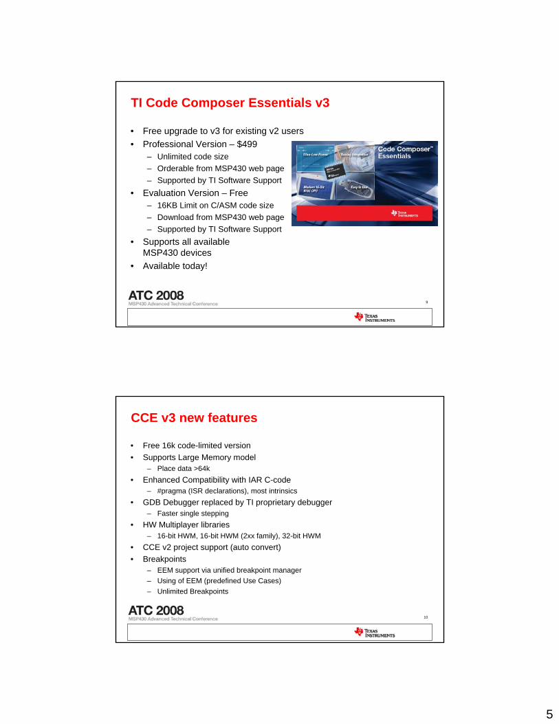
TI Code Composer Essentials v3
• Free upgrade to v3 for existing v2 users• Professional Version – $499
– Unlimited code size– Orderable from MSP430 web page– Supported by TI Software Support
• Evaluation Version – Free– 16KB Limit on C/ASM code size– Download from MSP430 web page– Supported by TI Software Support
• Supports all availableMSP430 devices
• Available today!
10
CCE v3 new features
• Free 16k code-limited version• Supports Large Memory model
– Place data >64k• Enhanced Compatibility with IAR C-code
– #pragma (ISR declarations), most intrinsics• GDB Debugger replaced by TI proprietary debugger
– Faster single stepping• HW Multiplayer libraries
– 16-bit HWM, 16-bit HWM (2xx family), 32-bit HWM• CCE v2 project support (auto convert)• Breakpoints
– EEM support via unified breakpoint manager– Using of EEM (predefined Use Cases) – Unlimited Breakpoints
6
11
Agenda
• Introduction to MSP430 Programming• Software tools overview• Hardware programming tools overview• Programming using JTAG• Programming using the ROM BSL• Introduction to the 5xx BSL• Tips and Tricks• Demos• Hands on
12
MSP430 Programmer Overview
• TI debugging tools– Mainly used for code development– Can be used for limited production programming– In-system programming and debugging solutions
• TI production programming tools– GANG Programmer– JTAG Replicator– Bootstrap Loader
• 3rd party tools– All or some of the above– Differentiated features & support– ATE solutions– Integrated production programming with test
7
13
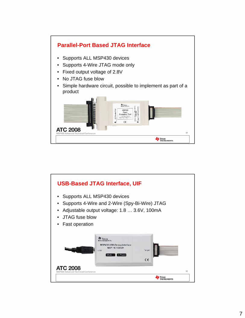
Parallel-Port Based JTAG Interface
• Supports ALL MSP430 devices• Supports 4-Wire JTAG mode only• Fixed output voltage of 2.8V• No JTAG fuse blow• Simple hardware circuit, possible to implement as part of a
product
14
USB-Based JTAG Interface, UIF
• Supports ALL MSP430 devices• Supports 4-Wire and 2-Wire (Spy-Bi-Wire) JTAG• Adjustable output voltage: 1.8 … 3.6V, 100mA• JTAG fuse blow• Fast operation
8
15
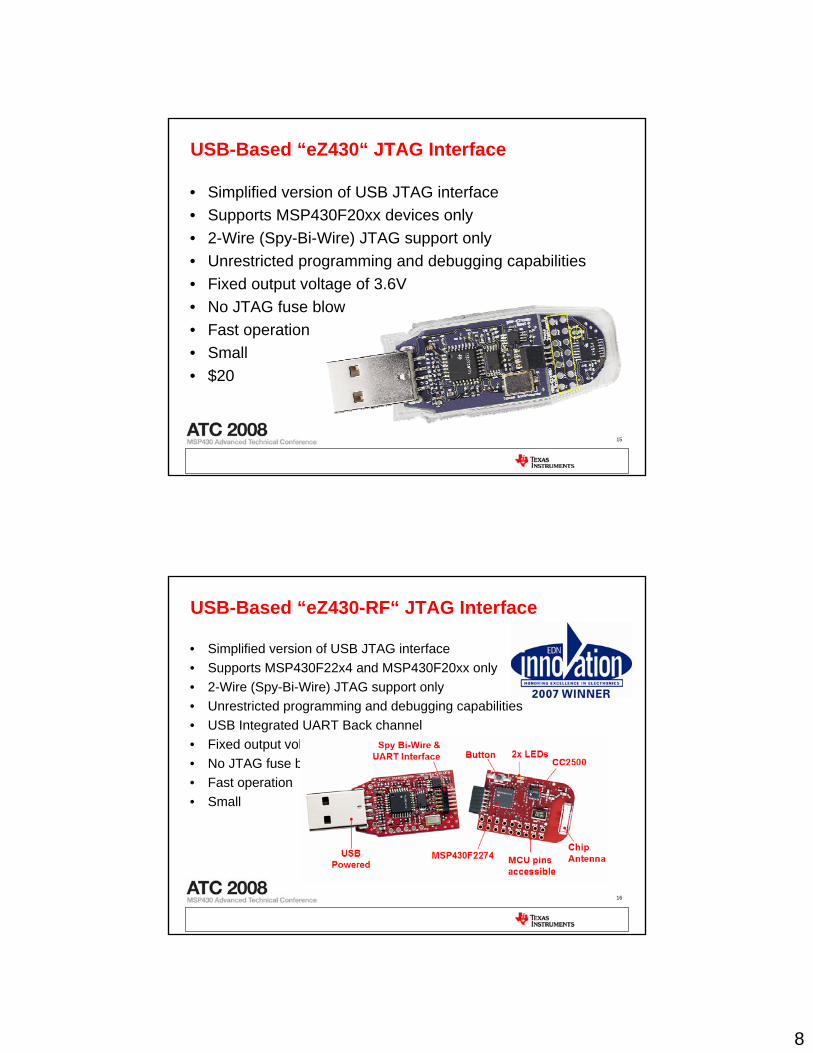
USB-Based “eZ430“ JTAG Interface
• Simplified version of USB JTAG interface• Supports MSP430F20xx devices only• 2-Wire (Spy-Bi-Wire) JTAG support only• Unrestricted programming and debugging capabilities• Fixed output voltage of 3.6V• No JTAG fuse blow• Fast operation• Small• $20
16
USB-Based “eZ430-RF“ JTAG Interface
• Simplified version of USB JTAG interface• Supports MSP430F22x4 and MSP430F20xx only• 2-Wire (Spy-Bi-Wire) JTAG support only• Unrestricted programming and debugging capabilities• USB Integrated UART Back channel• Fixed output voltage of 3.6V• No JTAG fuse blow• Fast operation• Small
9
17
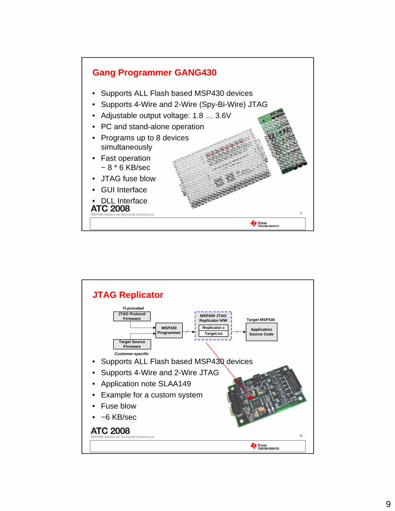
Gang Programmer GANG430
• Supports ALL Flash based MSP430 devices• Supports 4-Wire and 2-Wire (Spy-Bi-Wire) JTAG• Adjustable output voltage: 1.8 … 3.6V• PC and stand-alone operation• Programs up to 8 devices
simultaneously• Fast operation
~ 8 * 6 KB/sec• JTAG fuse blow• GUI Interface• DLL Interface
18
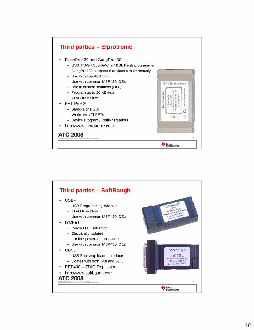
JTAG Replicator
Replicator.cTarget.txt
JTAG ProtocolFirmware
Target SourceFirmware
MSP430 JTAGReplicator H/W
ApplicationSource Code
Target MSP430
MSP430Programmer
TI-provided
Customer-specific
• Supports ALL Flash based MSP430 devices• Supports 4-Wire and 2-Wire JTAG• Application note SLAA149• Example for a custom system• Fuse blow• ~6 KB/sec
10
19
Third parties – Elprotronic
• FlashPro430 and GangPro430– USB JTAG / Spy-Bi-Wire / BSL Flash programmer– GangPro430 supports 6 devices simultaneously– Use with supplied GUI– Use with common MSP430 IDEs– Use in custom solutions (DLL)– Program up to 26 KByte/s– JTAG fuse blow
• FET-Pro430– Stand-alone GUI– Works with TI FETs– Device Program / Verify / Readout
• http://www.elprotronic.com
20
Third parties – SoftBaugh• USBP
– USB Programming Adapter– JTAG fuse blow– Use with common MSP430 IDEs
• ISOFET– Parallel FET interface– Electrically isolated– For line-powered applications– Use with common MSP430 IDEs
• UBSL– USB Bootstrap loader interface– Comes with both GUI and SDK
• REP430 – JTAG Replicator• http://www.softbaugh.com
11
21
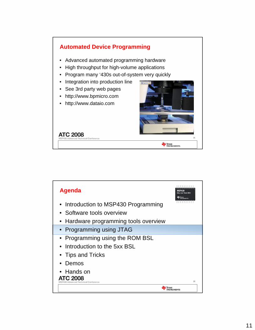
Automated Device Programming
• Advanced automated programming hardware • High throughput for high-volume applications• Program many ‘430s out-of-system very quickly• Integration into production line• See 3rd party web pages• http://www.bpmicro.com• http://www.dataio.com
22
Agenda
• Introduction to MSP430 Programming• Software tools overview• Hardware programming tools overview• Programming using JTAG• Programming using the ROM BSL• Introduction to the 5xx BSL• Tips and Tricks• Demos• Hands on
12
23
JTAG Fundamentals
• Two different protocols available– 4-Wire JTAG: Supported by all MSP430s– 2-Wire JTAG (“Spy-Bi-Wire”): Selected MSP430F2xx devices
• TI MSP430 JTAG Tools– Flash Emulation Tool (FET): USB & Parallel Port– Gang Programmer GANG430– JTAG Replicator Hardware
• Applications Collateral– Programming a Flash-Based MSP430 Using the JTAG Interface
Application note (also covers JTAG Replicator Hardware) – SLAA149– MSP430.DLL Developer Distribution Package (2H2007)– FET User’s Guide (for IAR and CCE)
24
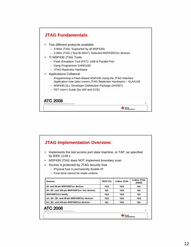
JTAG Implementation Overview
• Implements the test access port state machine, or TAP, as specified by IEEE 1149.1
• MSP430 JTAG does NOT implement boundary scan• Access is protected by JTAG security fuse
– Physical fuse to permanently disable I/F– Fuse blow cannot be made undone
NOYESYES20- and 28-pin MSP430F1xx devices
NOYESNO64-, 80-, and 100-pin MSP430F2xx devices
YESYESYES14-, 20-, 28-, and 38-pin MSP430F2xx devices
NOYESYESMSP430F21x1 family
NOYESNO64-, 80-, and 100-pin MSP430F1xx / 4xx devices
2-Wire JTAG (SBW)4-Wire JTAGTEST PinDevices
13
25
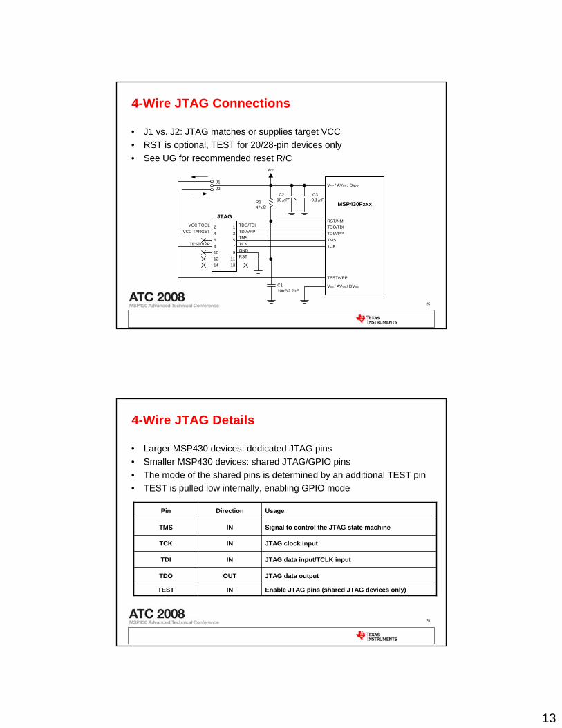
4-Wire JTAG Connections
• J1 vs. J2: JTAG matches or supplies target VCC• RST is optional, TEST for 20/28-pin devices only• See UG for recommended reset R/C
13579
1113
2468101214
VCC / AVCC / DVCC
VSS / AVSS / DVSS
TEST/VPP
TDO/TDITDI/VPPTMSTCK
MSP430Fxxx
RST/NMI
10μF 0.1μF
47kΩ
TDO/TDITDI/VPPTMSTCKGND
TEST/VPP
VCC
RST
JTAG
R1
VCC TOOLVCC TARGET
10nF/2.2nFC1
C2 C3
J1J2
26
4-Wire JTAG Details
• Larger MSP430 devices: dedicated JTAG pins• Smaller MSP430 devices: shared JTAG/GPIO pins• The mode of the shared pins is determined by an additional TEST pin• TEST is pulled low internally, enabling GPIO mode
Enable JTAG pins (shared JTAG devices only)INTEST
JTAG data outputOUTTDO
JTAG data input/TCLK inputINTDI
JTAG clock inputINTCK
Signal to control the JTAG state machineINTMS
UsageDirectionPin
14
27
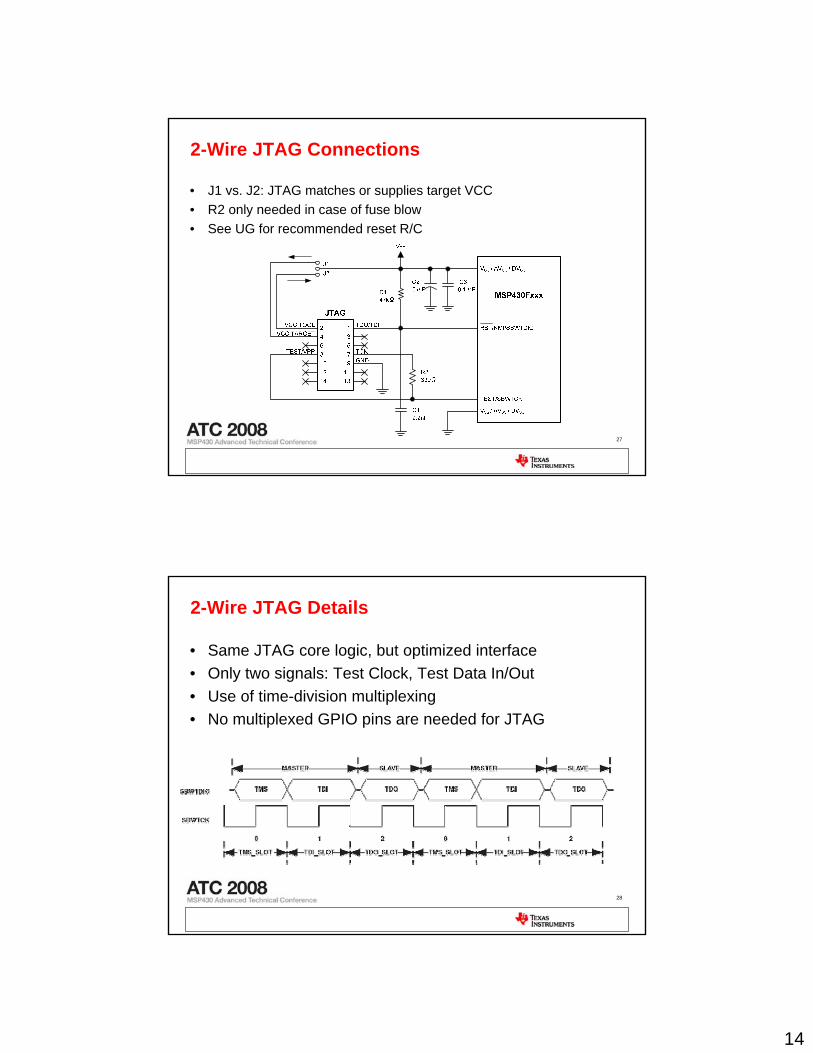
2-Wire JTAG Connections
• J1 vs. J2: JTAG matches or supplies target VCC• R2 only needed in case of fuse blow• See UG for recommended reset R/C
28
2-Wire JTAG Details
• Same JTAG core logic, but optimized interface• Only two signals: Test Clock, Test Data In/Out• Use of time-division multiplexing• No multiplexed GPIO pins are needed for JTAG
15
29
MSP430.DLL
• Provides an API to access a target MSP430• For use with USB / Parallel Port JTAG IF• Pair of two Windows DLL library modules
– MSP430.DLL – Contains all device control functions– HIL.DLL – Abstracts the physical parallel-port interface
• Included with all MSP430 IDEs• Built-in functionality
– Target device identification– Target voltage control– Full device memory access– Full device control / debug– 4-Wire and 2-wire JTAG access– Parallel und USB JTAG emulator
30
GANG430.DLL
• Alternate method of using GANG430 without using the supplied GUI• Part of the GANG430 software package• Available in the GANG430 folder on the TI Web Page• Direct access to GANG430 functions:
– Device programming & Verify– Program, erase, fuse blow configurable– Supply voltage selection– Variable serial communication speed– Can use TI txt or Intel hex output directly from compiler– Fast and Reliable mass programming technique– Target readout supported– Access of target SFRs
• Comes with application examples
16
31
GANG430.DLL
• Possible to send raw commands out the PC serial port: described in Gang Programmer User’s Guide
• Using the TI-provided GANG430.DLL is easier and more reliable than a custom solution
• Example programs provided: C, C++, LabView, VB– <Install Dir>\GANG\DLL_usage_examples\
• Custom uses:– Target serialization– Random number seeding– Temporary test program loading
32
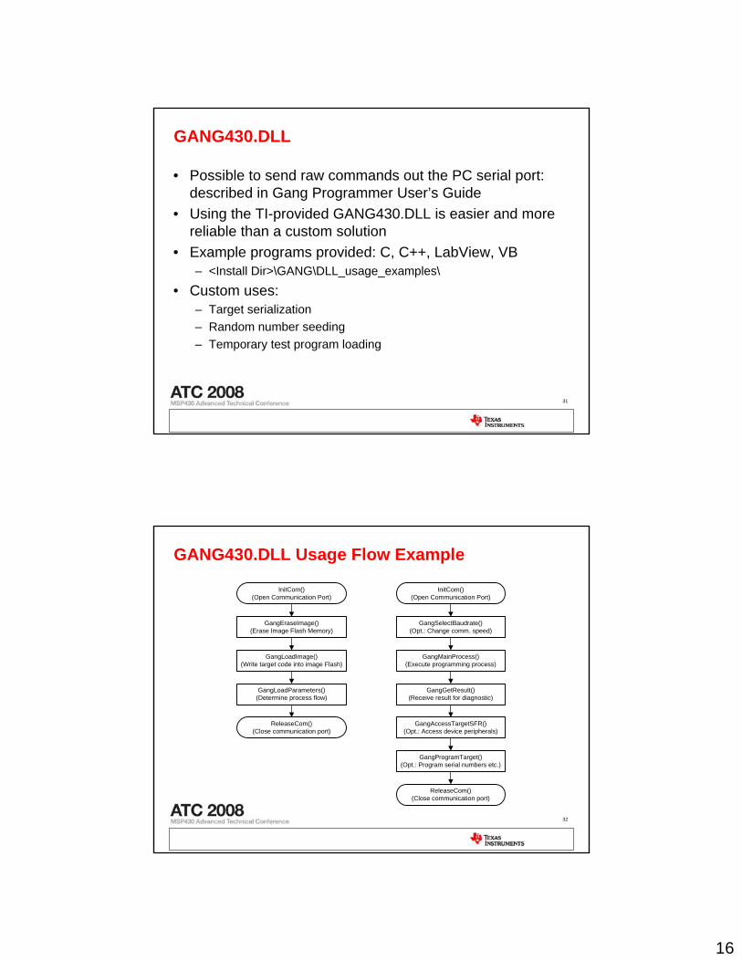
GANG430.DLL Usage Flow Example
GangLoadImage()(Write target code into image Flash)
GangLoadParameters()(Determine process flow)
InitCom()(Open Communication Port)
ReleaseCom()(Close communication port)
GangEraseImage()(Erase Image Flash Memory)
GangMainProcess()(Execute programming process)
GangGetResult()(Receive result for diagnostic)
InitCom()(Open Communication Port)
GangSelectBaudrate()(Opt.: Change comm. speed)
GangAccessTargetSFR()(Opt.: Access device peripherals)
GangProgramTarget()(Opt.: Program serial numbers etc.)
ReleaseCom()(Close communication port)
17
33
Agenda
• Introduction to MSP430 Programming• Software tools overview• Hardware programming tools overview• Programming using JTAG• Programming using the ROM BSL• Introduction to the 5xx BSL• Tips and Tricks• Demos• Hands on
34
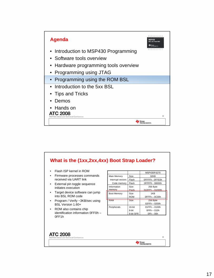
What is the (1xx,2xx,4xx) Boot Strap Loader?
• Flash ISP kernel in ROM• Firmware processes commands
received via UART link• External pin toggle sequence
initiates execution• Target device software can jump
into BSL ROM code• Program / Verify ~3KB/sec using
BSL Version 1.60+• ROM also contains chip
identification information 0FF0h –0FF1h
01FFh – 0100h0FFh – 010h
0Fh – 00h
16-bit8-bit8-bit SFR
Peripherals
256 Byte02FFh – 0200h
SizeRAM
1KB0FFFh – 0C00h
SizeROM
Boot Memory
256 Byte010FFh – 01000h
SizeFlash
Information memory
0FFFFh - 08000hFlashCode memory0FFFFh - 0FFE0hFlashInterrupt vectors
32KBSizeMain MemoryMSP430F4270
18
35
Using the BSL
• Features of the MSP430 Bootstrap Loader, SLAA089 – Illustrates BSL pin toggle sequence for all devices– Defines BSL protocol & commands– Documents BSL ROM code versions & features– Describes a stand-alone MSP430 based “BSL Replicator” design
• Application of Bootstrap Loader in MSP430 with Flash Hardware, Software Proposal, SLAA096 – Proposal for MSP430 hardware for interfacing from a PC to the BSL– Software framework for low-level communication via DLL– Hardware schematics– Command line information
• Use these application reports for BSL use & programmer tool development
36
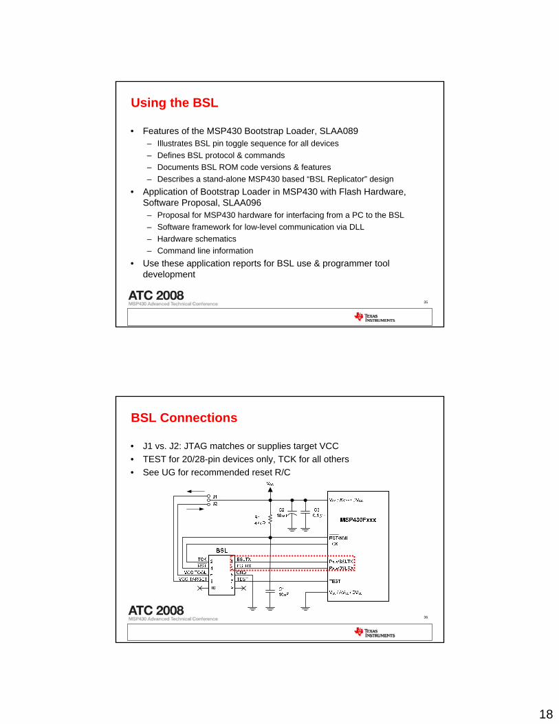
BSL Connections
• J1 vs. J2: JTAG matches or supplies target VCC• TEST for 20/28-pin devices only, TCK for all others• See UG for recommended reset R/C
19
37
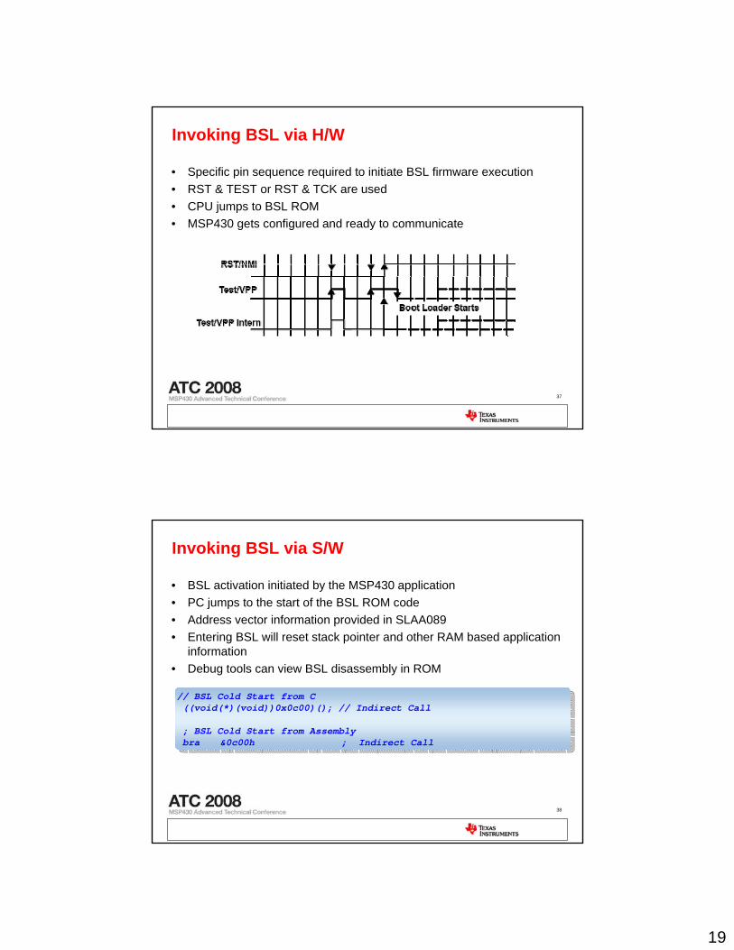
Invoking BSL via H/W
• Specific pin sequence required to initiate BSL firmware execution• RST & TEST or RST & TCK are used• CPU jumps to BSL ROM• MSP430 gets configured and ready to communicate
38
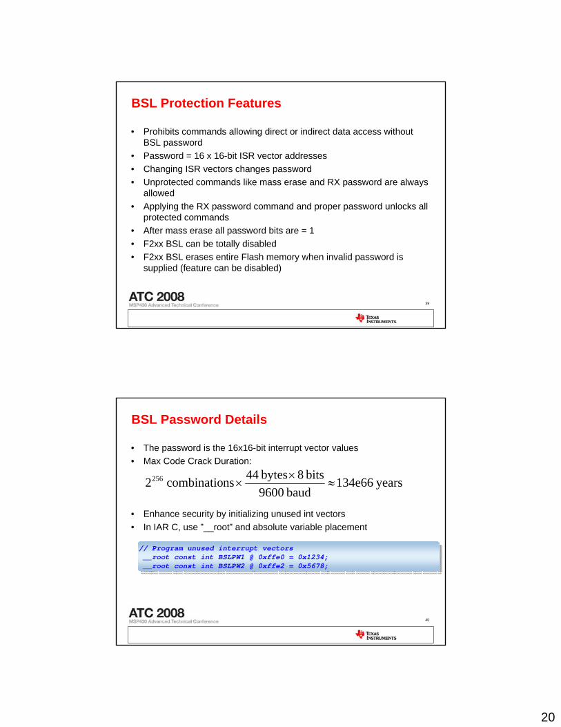
Invoking BSL via S/W
• BSL activation initiated by the MSP430 application• PC jumps to the start of the BSL ROM code• Address vector information provided in SLAA089• Entering BSL will reset stack pointer and other RAM based application
information• Debug tools can view BSL disassembly in ROM
// BSL Cold Start from C((void(*)(void))0x0c00)(); // Indirect Call
; BSL Cold Start from Assemblybra &0c00h ; Indirect Call
// BSL Cold Start from C((void(*)(void))0x0c00)(); // Indirect Call
; BSL Cold Start from Assemblybra &0c00h ; Indirect Call
20
39
BSL Protection Features
• Prohibits commands allowing direct or indirect data access without BSL password
• Password = 16 x 16-bit ISR vector addresses• Changing ISR vectors changes password• Unprotected commands like mass erase and RX password are always
allowed• Applying the RX password command and proper password unlocks all
protected commands• After mass erase all password bits are = 1 • F2xx BSL can be totally disabled• F2xx BSL erases entire Flash memory when invalid password is
supplied (feature can be disabled)
40
BSL Password Details
• The password is the 16x16-bit interrupt vector values• Max Code Crack Duration:
• Enhance security by initializing unused int vectors• In IAR C, use ”__root” and absolute variable placement
years 134e66 baud9600
bits 8 bytes 44 nscombinatio 2256 ≈×
×
// Program unused interrupt vectors__root const int BSLPW1 @ 0xffe0 = 0x1234;__root const int BSLPW2 @ 0xffe2 = 0x5678;
// Program unused interrupt vectors__root const int BSLPW1 @ 0xffe0 = 0x1234;__root const int BSLPW2 @ 0xffe2 = 0x5678;
21
41
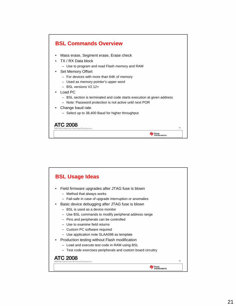
BSL Commands Overview
• Mass erase, Segment erase, Erase check• TX / RX Data block
– Use to program and read Flash memory and RAM• Set Memory Offset
– For devices with more than 64K of memory– Used as memory pointer’s upper word– BSL versions V2.12+
• Load PC– BSL section is terminated and code starts execution at given address– Note: Password protection is not active until next POR
• Change baud rate– Select up to 38,400 Baud for higher throughput
42
BSL Usage Ideas
• Field firmware upgrades after JTAG fuse is blown– Method that always works– Fail-safe in case of upgrade interruption or anomalies
• Basic device debugging after JTAG fuse is blown– BSL is used as a device monitor– Use BSL commands to modify peripheral address range– Pins and peripherals can be controlled– Use to examine field returns– Custom PC software required– Use application note SLAA098 as template
• Production testing without Flash modification– Load and execute test code in RAM using BSL– Test code exercises peripherals and custom board circuitry
22
43
Agenda
• Introduction to MSP430 Programming• Software tools overview• Hardware programming tools overview• Programming using JTAG• Programming using the ROM BSL• Introduction to the 5xx BSL• Tips and Tricks• Demos• Hands on
44
Overview of 5xx BSL
• Built in System level protection– 5xx BSL has a flash area of selectable size, from 512 bytes-2k bytes of
protected flash– Flash area can be protected against read and write– PC can not jump into protected flash area– Can be programmed, erased, or disabled through JTAG
• Built in BSL features– Modular design for code re-use– 16x16 Password like previous BSLs– Automatic erase on incorrect password– Larger buffer size for data transmission– UART Communication programmed into BSL flash
23
45
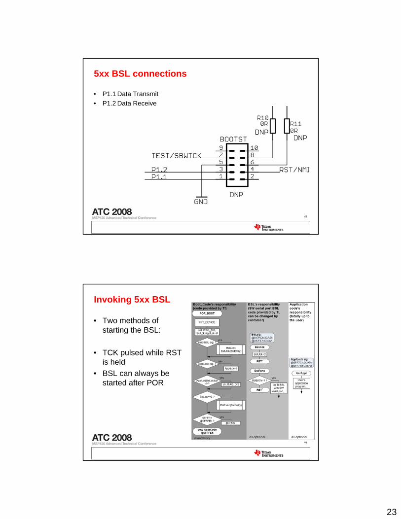
5xx BSL connections
• P1.1 Data Transmit• P1.2 Data Receive
46
Invoking 5xx BSL
• Two methods of starting the BSL:
• TCK pulsed while RST is held
• BSL can always be started after POR
24
47
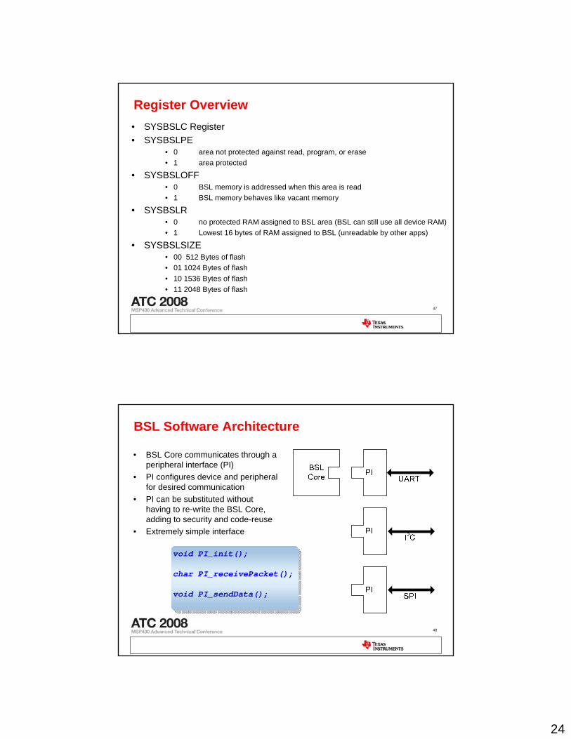
Register Overview• SYSBSLC Register• SYSBSLPE
• 0 area not protected against read, program, or erase• 1 area protected
• SYSBSLOFF• 0 BSL memory is addressed when this area is read• 1 BSL memory behaves like vacant memory
• SYSBSLR• 0 no protected RAM assigned to BSL area (BSL can still use all device RAM)• 1 Lowest 16 bytes of RAM assigned to BSL (unreadable by other apps)
• SYSBSLSIZE• 00 512 Bytes of flash• 01 1024 Bytes of flash• 10 1536 Bytes of flash• 11 2048 Bytes of flash
48
BSL Software Architecture
• BSL Core communicates through a peripheral interface (PI)
• PI configures device and peripheral for desired communication
• PI can be substituted without having to re-write the BSL Core, adding to security and code-reuse
• Extremely simple interface
void PI_init();
char PI_receivePacket();
void PI_sendData();
void PI_init();
char PI_receivePacket();
void PI_sendData();
25
49
BSL Software Architecture
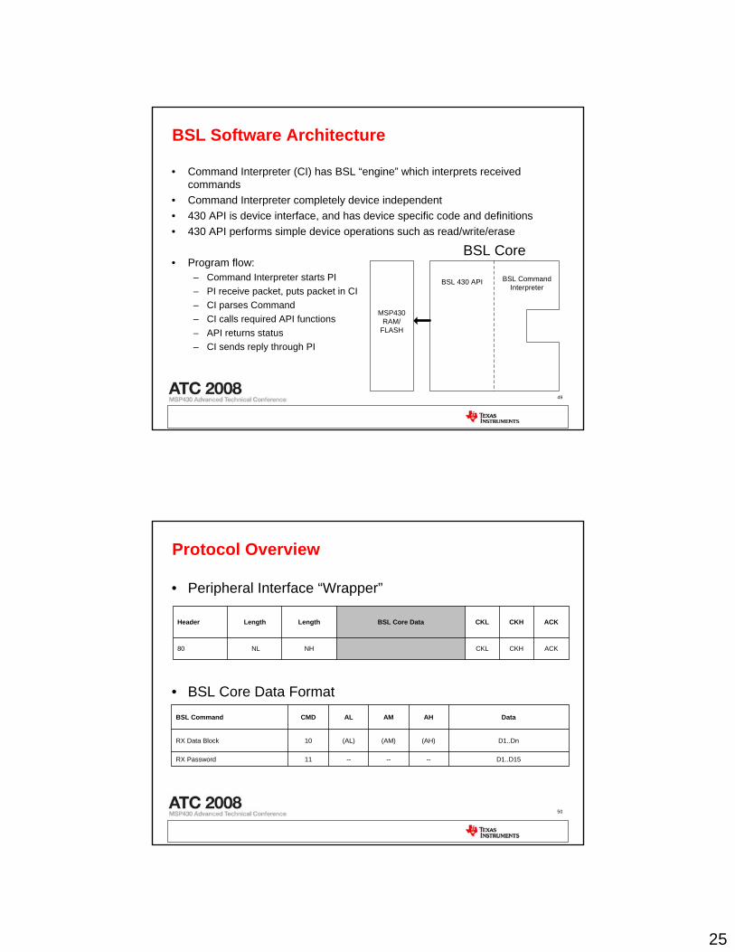
• Command Interpreter (CI) has BSL “engine” which interprets received commands
• Command Interpreter completely device independent• 430 API is device interface, and has device specific code and definitions• 430 API performs simple device operations such as read/write/erase
• Program flow:– Command Interpreter starts PI– PI receive packet, puts packet in CI– CI parses Command– CI calls required API functions– API returns status– CI sends reply through PI
BSL Core
BSL Command Interpreter
BSL 430 API
MSP430 RAM/
FLASH
50
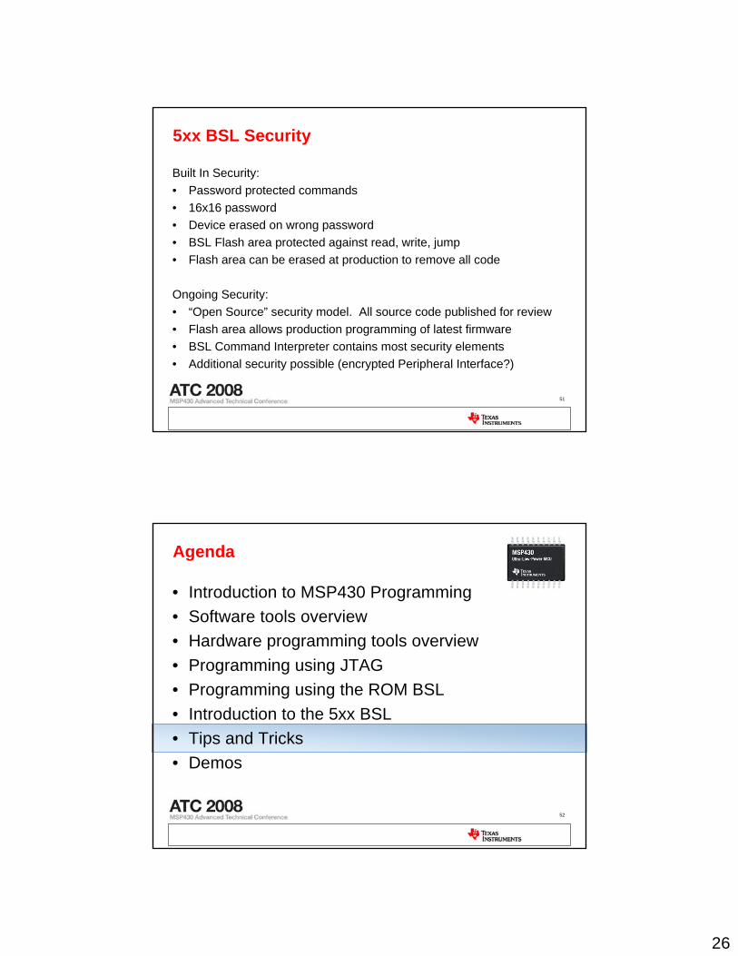
Protocol Overview
• Peripheral Interface “Wrapper”
• BSL Core Data Format
ACKCKHCKLNHNL80
ACKCKHCKLBSL Core DataLengthLengthHeader
D1..D15------11RX Password
D1..Dn(AH)(AM)(AL)10RX Data Block
DataAHAMALCMDBSL Command
26
51
5xx BSL Security
Built In Security:• Password protected commands• 16x16 password• Device erased on wrong password• BSL Flash area protected against read, write, jump• Flash area can be erased at production to remove all code
Ongoing Security:• “Open Source” security model. All source code published for review• Flash area allows production programming of latest firmware• BSL Command Interpreter contains most security elements• Additional security possible (encrypted Peripheral Interface?)
52
Agenda
• Introduction to MSP430 Programming• Software tools overview• Hardware programming tools overview• Programming using JTAG• Programming using the ROM BSL• Introduction to the 5xx BSL• Tips and Tricks• Demos
27
53
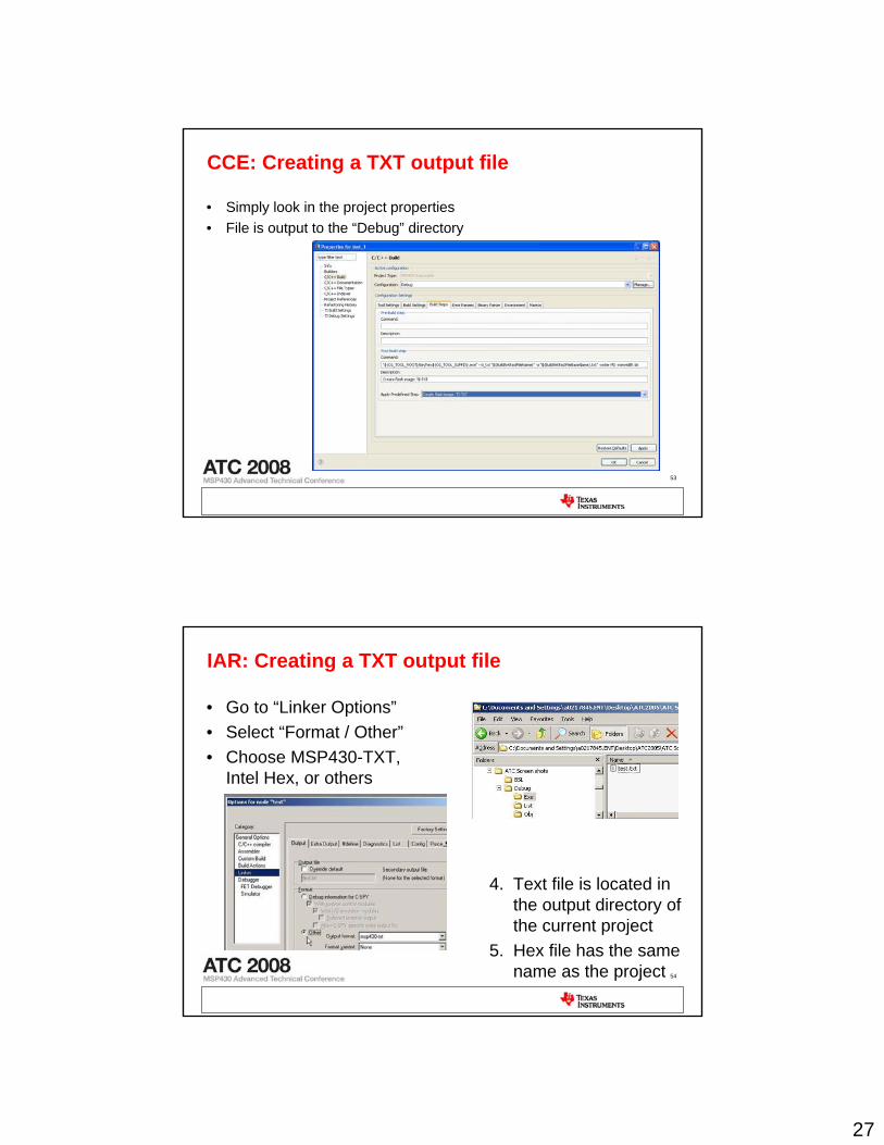
CCE: Creating a TXT output file
• Simply look in the project properties• File is output to the “Debug” directory
54
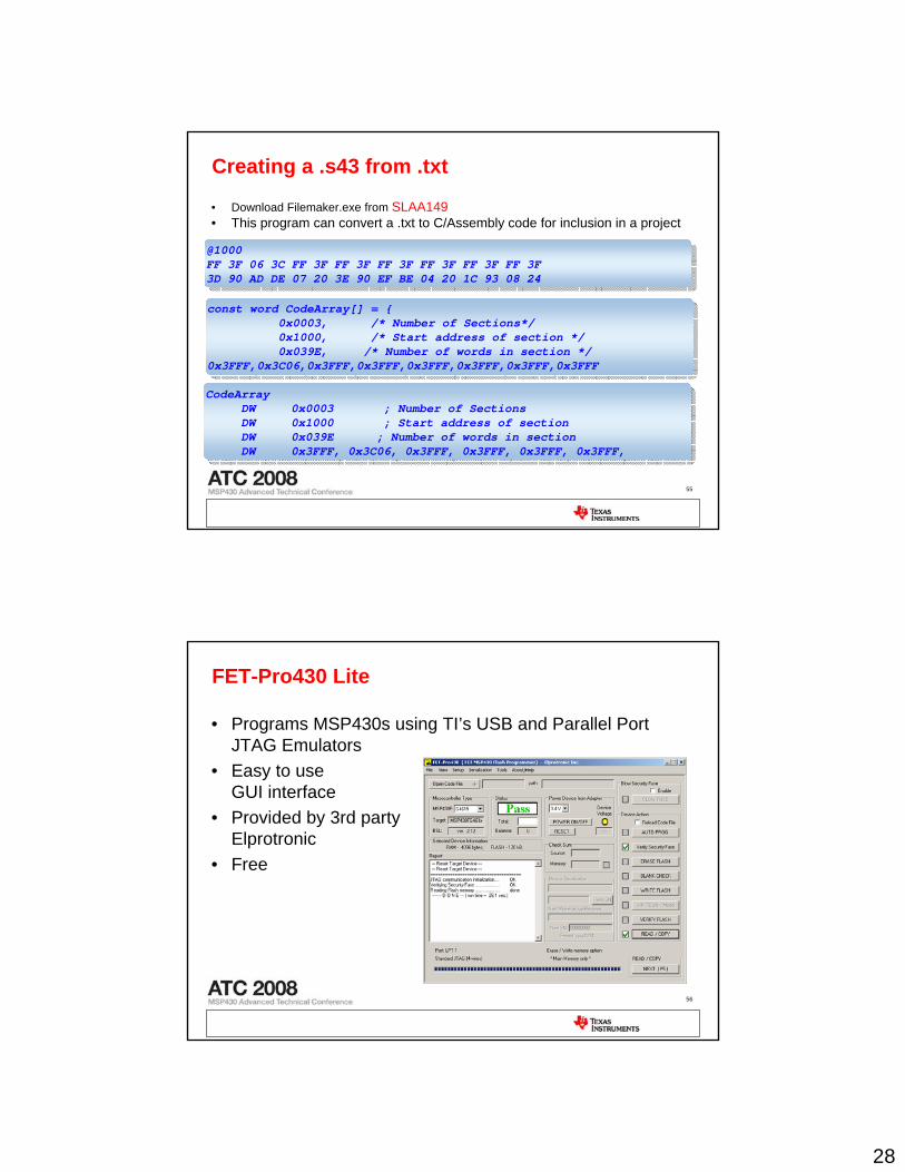
IAR: Creating a TXT output file
• Go to “Linker Options”• Select “Format / Other”• Choose MSP430-TXT,
Intel Hex, or others
4. Text file is located in the output directory of the current project
5. Hex file has the same name as the project
28
55
• Download Filemaker.exe from SLAA149• This program can convert a .txt to C/Assembly code for inclusion in a project
Creating a .s43 from .txt
@1000FF 3F 06 3C FF 3F FF 3F FF 3F FF 3F FF 3F FF 3F3D 90 AD DE 07 20 3E 90 EF BE 04 20 1C 93 08 24
@1000FF 3F 06 3C FF 3F FF 3F FF 3F FF 3F FF 3F FF 3F3D 90 AD DE 07 20 3E 90 EF BE 04 20 1C 93 08 24
const word CodeArray[] = {0x0003, /* Number of Sections*/0x1000, /* Start address of section */0x039E, /* Number of words in section */
0x3FFF,0x3C06,0x3FFF,0x3FFF,0x3FFF,0x3FFF,0x3FFF,0x3FFF
const word CodeArray[] = {0x0003, /* Number of Sections*/0x1000, /* Start address of section */0x039E, /* Number of words in section */
0x3FFF,0x3C06,0x3FFF,0x3FFF,0x3FFF,0x3FFF,0x3FFF,0x3FFF
CodeArrayDW 0x0003 ; Number of SectionsDW 0x1000 ; Start address of section DW 0x039E ; Number of words in section DW 0x3FFF, 0x3C06, 0x3FFF, 0x3FFF, 0x3FFF, 0x3FFF,
CodeArrayDW 0x0003 ; Number of SectionsDW 0x1000 ; Start address of section DW 0x039E ; Number of words in section DW 0x3FFF, 0x3C06, 0x3FFF, 0x3FFF, 0x3FFF, 0x3FFF,
56
FET-Pro430 Lite
• Programs MSP430s using TI’s USB and Parallel Port JTAG Emulators
• Easy to useGUI interface
• Provided by 3rd partyElprotronic
• Free
29
57
Thank you


![Victaulic G-103 condensed - Emco Westlund website [1]](https://img.pdfslide.us/doc/110x75/568bd7aa1a28ab2034a08dd2/victaulic-g-103-condensed-emco-westlund-website-1.jpg)