Embed Size (px)
Citation preview

© 2006 Texas Instruments Inc, Slide 1
MSP430 Timers In-Depth
Keith QuiringMSP430 Applications Engineer
Texas Instruments

© 2006 Texas Instruments Inc, Slide 2
• Introduction• Basic Timer• RTC• Watchdog Timer (WDT/WDT+)• Timer_A• Timer_B• Summary and Applications
Agenda

© 2006 Texas Instruments Inc, Slide 3
Introduction• Timers: Essential to almost any embedded application
Generate fixed-period eventsPeriodic wakeupCount edgesReplacing delay loops with timer calls allows CPU to sleep, consuming much less power
• Five types of MSP430 timer modules• Different tasks call for different timers. But which one?• We will:
Discuss all five timer modulesExtract the unique characteristics of each, compare/contrast themSpend majority of time on Timer_A/BLook at real-world application examples

© 2006 Texas Instruments Inc, Slide 4
• Introduction• Basic Timer• RTC• Watchdog Timer (WDT/WDT+)• Timer_A• Timer_B• Summary and Applications
Agenda

© 2006 Texas Instruments Inc, Slide 5
Basic Timer: Overview
• Found only on ‘4xx• Primary characteristics
Clock for LCD moduleGood choice for RTC implementationBasic interval timerSimple interrupt capability
• Wide range of intervals – up to two seconds
© 2006 Texas Instruments Inc, Slide 6
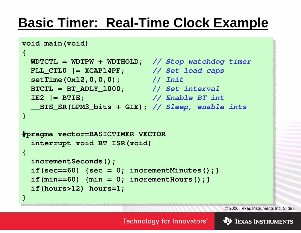
Basic Timer: Real-Time Clock Examplevoid main(void){WDTCTL = WDTPW + WDTHOLD; // Stop watchdog timerFLL_CTL0 |= XCAP14PF; // Set load capssetTime(0x12,0,0,0); // InitBTCTL = BT_ADLY_1000; // Set intervalIE2 |= BTIE; // Enable BT int__BIS_SR(LPM3_bits + GIE); // Sleep, enable ints
}
#pragma vector=BASICTIMER_VECTOR__interrupt void BT_ISR(void){incrementSeconds();if(sec==60) {sec = 0; incrementMinutes();}if(min==60) {min = 0; incrementHours();}if(hours>12) hours=1;
}
void main(void){WDTCTL = WDTPW + WDTHOLD; // Stop watchdog timerFLL_CTL0 |= XCAP14PF; // Set load capssetTime(0x12,0,0,0); // InitBTCTL = BT_ADLY_1000; // Set intervalIE2 |= BTIE; // Enable BT int__BIS_SR(LPM3_bits + GIE); // Sleep, enable ints
}
#pragma vector=BASICTIMER_VECTOR__interrupt void BT_ISR(void){incrementSeconds();if(sec==60) {sec = 0; incrementMinutes();}if(min==60) {min = 0; incrementHours();}if(hours>12) hours=1;
}

© 2006 Texas Instruments Inc, Slide 7
Basic Timer: LCD Drive ExampleSet Basic Timer for LCD refresh
void main(void){int i;
WDTCTL = WDTPW + WDTHOLD; FLL_CTL0 |= XCAP14PF; LCDCTL = LCDP2 + LCD4MUX + LCDON; BTCTL = BTFRFQ1; // LCD freq=ACLK/128P5SEL = 0xFC; // Set LCD pins
for (;;)for (i=0; i<7; ++i) // Display #LCDMEM[i] = digit[i];
}
void main(void){int i;
WDTCTL = WDTPW + WDTHOLD; FLL_CTL0 |= XCAP14PF; LCDCTL = LCDP2 + LCD4MUX + LCDON; BTCTL = BTFRFQ1; // LCD freq=ACLK/128P5SEL = 0xFC; // Set LCD pins
for (;;)for (i=0; i<7; ++i) // Display #LCDMEM[i] = digit[i];
}

© 2006 Texas Instruments Inc, Slide 8
Basic Timer: Thermostat Examplevoid main(void) {<< Code to initialize WDT/caps/LCD/IOs >>
BTCTL = BT_ADLY_2000; // Two secondsBTCTL |= BT_fLCD_DIV256; // LCD=ACLK/256IE2 = BTIE; // Enable ints
while(1)checkTempAndUpdateDisplay();
}
#pragma vector=BASICTIMER_VECTOR__interrupt void basic_timer(void) {if(count&0x01) // Every other time__BIC_SR_IRQ(LPM3_bits); // Exit after return
count++;}
void main(void) {<< Code to initialize WDT/caps/LCD/IOs >>
BTCTL = BT_ADLY_2000; // Two secondsBTCTL |= BT_fLCD_DIV256; // LCD=ACLK/256IE2 = BTIE; // Enable ints
while(1)checkTempAndUpdateDisplay();
}
#pragma vector=BASICTIMER_VECTOR__interrupt void basic_timer(void) {if(count&0x01) // Every other time__BIC_SR_IRQ(LPM3_bits); // Exit after return
count++;}

© 2006 Texas Instruments Inc, Slide 9
• Introduction• Basic Timer• RTC• Watchdog Timer (WDT/WDT+)• Timer_A• Timer_B• Summary and Applications
Agenda

© 2006 Texas Instruments Inc, Slide 10
Real-Time Clock Module: Overview• First introduced on ‘FG4619
(new module)• Extension of the Basic Timer• Two modes
Counter: BT is unaltered, and there’s now an additional 32-bit counterCalendar: BT becomes part of RTC module, all of which drives an RTC
• BT and RTC share interrupt vectors

© 2006 Texas Instruments Inc, Slide 11
RTC: Calendar Mode• Clock functions handled
automatically• Registers for:
YearMonthDateDay of weekHourMinuteSecond
• Either BCD or hex format• No generic BT
functionality
• Handles leap year calculation
• RTC interruptCan be enabled/disabledTriggered on turnover of min/hr/midnight/noon
• Intervals from every minute to once a day; one-second intervals no longer required to implement RTC
• No “alarm clock” (exact time) interrupt – easily implemented in code

© 2006 Texas Instruments Inc, Slide 12
RTC: Real-Time Clock Examplevoid main(void) {WDTCTL = WDTPW+WDTHOLD; // Stop the dogRTCCTL = RTCBCD+RTCHOLD+RTCMODE_3+RTCTEV_0+RTCIE;
// Enable, BCD, int every minuteRTCSEC = 0x00; // Set SecondsRTCMIN = 0x00; // Set MinutesRTCHOUR = 0x08; // Set HoursRTCDOW = 0x02; // Set DOWRTCDAY = 0x23; // Set DayRTCMON = 0x08; // Set MonthRTCYEAR = 0x2005; // Set YearRTCCTL &= ~RTCHOLD; // Enable RTC__BIS_SR(LPM3_bits+GIE);// Enter LPM3 w/ interrupt
}
#pragma vector=BASICTIMER_VECTOR__interrupt void basic_timer(void) {P5OUT ^= 0x02; // Toggle P5.1 every minute
}
void main(void) {WDTCTL = WDTPW+WDTHOLD; // Stop the dogRTCCTL = RTCBCD+RTCHOLD+RTCMODE_3+RTCTEV_0+RTCIE;
// Enable, BCD, int every minuteRTCSEC = 0x00; // Set SecondsRTCMIN = 0x00; // Set MinutesRTCHOUR = 0x08; // Set HoursRTCDOW = 0x02; // Set DOWRTCDAY = 0x23; // Set DayRTCMON = 0x08; // Set MonthRTCYEAR = 0x2005; // Set YearRTCCTL &= ~RTCHOLD; // Enable RTC__BIS_SR(LPM3_bits+GIE);// Enter LPM3 w/ interrupt
}
#pragma vector=BASICTIMER_VECTOR__interrupt void basic_timer(void) {P5OUT ^= 0x02; // Toggle P5.1 every minute
}

© 2006 Texas Instruments Inc, Slide 13
RTC: Counter Mode• BT remains “intact”• RTC provides an additional 32-bit counter• BT/RTC counters share one interrupt vector• In effect, the 32-bit counter replaces the 16-bit one• RTCIE bit selects whether interrupt generated by RTC
or BT counters• If set, interrupt generated by overflow of RTC counter
(selectable 8/16/24/32-bit)• Interrupt vector is shared with BT

© 2006 Texas Instruments Inc, Slide 14
RTC: BT/RTC Interval Timer Example• Setting RTCIE in interval mode causes interrupt to be
generated from 32-bit RTC interval countervoid main(void){WDTCTL = WDTPW + WDTHOLD; FLL_CTL0 |= XCAP18PF; P5DIR |= 0x02; BTCTL=BTSSEL+BT_fCLK2_DIV256; //1MHz/256 = ~244us Interval RTCCTL =RTCMODE_1+RTCTEV_0+RTCIE; // 1MHz/(128*256) =32 HzIE2 |= BTIE; __BIS_SR(LPM0_bits + GIE);
}
#pragma vector=BASICTIMER_VECTOR__interrupt void basic_timer_ISR(void){P5OUT ^= 0x02; // Toggle P5.1
}
void main(void){WDTCTL = WDTPW + WDTHOLD; FLL_CTL0 |= XCAP18PF; P5DIR |= 0x02; BTCTL=BTSSEL+BT_fCLK2_DIV256; //1MHz/256 = ~244us Interval RTCCTL =RTCMODE_1+RTCTEV_0+RTCIE; // 1MHz/(128*256) =32 HzIE2 |= BTIE; __BIS_SR(LPM0_bits + GIE);
}
#pragma vector=BASICTIMER_VECTOR__interrupt void basic_timer_ISR(void){P5OUT ^= 0x02; // Toggle P5.1
}

© 2006 Texas Instruments Inc, Slide 15
• Introduction• Basic Timer• RTC• Watchdog Timer (WDT/WDT+)• Timer_A• Timer_B• Summary and Applications
Agenda

© 2006 Texas Instruments Inc, Slide 16
Watchdog (WDT/+) Module: Overview• Found on all MSP430 devices• Two flavors: WDT & WDT+• Two modes
WatchdogInterval timer
• Access password protected• Separate interrupt vectors for POR
and interval timer• Sourced by ACLK or SMCLK• Controls RST/NMI pin mode• WDT+ adds failsafe/protected clock

© 2006 Texas Instruments Inc, Slide 17
WDT: Watchdog Function• Controlled start if s/w problem occurs• Code must “pet” the “dog” before interval
expires, otherwise PUC• Selectable intervals• Powers up active as watchdog w/ ~32ms
reset – YOUR CODE MUST INITIALIZE THE WDT
• In addition to PUC, WDTIFG sources reset vector interrupt
• Code can use WDTIFG to determine whether dog caused interrupt

© 2006 Texas Instruments Inc, Slide 18
WDT: Common Design Issues• Program keeps resetting itself!• Program acting wacky – how did execution get to that
place? Try setting interrupt near beginning of main() to see if code is re-starting
• CPU seems to freeze before even getting to first instruction
Is this a C program with a lot of initialized memory?Generally can occur only with very large-memory versions of the deviceSolution: Use __low_level_init() function, stop watchdog there
void main(void) {WDTCTL = WDTPW+WDTHOLD; // Stop the dog..
}
void main(void) {WDTCTL = WDTPW+WDTHOLD; // Stop the dog..
}

© 2006 Texas Instruments Inc, Slide 19
WDT: Interval Timer Function• No PUC issued when interval
is reached• If WDTIE and GIE set when
interval is reached, a WDT interval interrupt generated instead of reset interrupt
• Selectable intervals

© 2006 Texas Instruments Inc, Slide 20
• Introduction• Basic Timer• RTC• Watchdog Timer (WDT/WDT+)• Timer_A• Timer_B• Summary and Applications
Agenda

© 2006 Texas Instruments Inc, Slide 21
Timer_A Module: Overview• The most versatile • Async 16-bit timer/counter• Four input clocks, including
externally-sourced• Selectable count mode • Extensive interrupt capability• Up to three capture/compare
registers (CCR) generate events when value reached
• “Capture” or “Compare” mode• Output not only interrupts, but
also “output signals”• Extensive connections to other
modules

© 2006 Texas Instruments Inc, Slide 22
Timer_A: Capture Mode• Measure time before a signal event
occurs• Why not just use a CPU interrupt and
have CPU fetch timer value?Extra cycles expireDependent on ints being enabled
• Input signal from:External pinInternal signal (i.e., Comp_A)Vcc/GND
• Edge direction – programmable• Applications:
Analog signal rising to Comp_A thresholdSlope ADCFrequency measurementVcc threshold detect (via voltage divider)

© 2006 Texas Instruments Inc, Slide 23
Timer_A: Compare Mode• Cause an event after a defined period (exact opposite
of capture mode)• What kind of event?
CPU interruptModules tied internally to timer output (DMA, start ADC/DAC conversion)External components
• Applications:PWM generationRTCThermostatTimer_A UART

© 2006 Texas Instruments Inc, Slide 24
Timer_A: Count Modes• Determines pattern of counter direction
What will it do when it rolls over?Does it always count up? Maybe down?What is the maximum value?
• Typically used in compare mode to generate cyclical events
• Can apply to capture mode in measuring cyclical events
• The modes:Continuous: Up to FFFF, rolls over to 0000, back up to FFFF, etc.Up: Up to value specified by CCR0, rolls over to 0000, back up to CCR0 value, etc.Up/down: Up to value specified by CCR0, count down to 0000, back up to CCR0 value, etc.

© 2006 Texas Instruments Inc, Slide 25
Timer_A: Count ModesUp
Continuous
Up to FFFF, rolls over to 0000, back up to FFFF, etc.
Up to value specified by CCR0, rolls over to 0000, back up to CCR0 value, etc.
Up/Down
Up to value in CCR0, count down to 0000, back up to value in CCR0, etc.

© 2006 Texas Instruments Inc, Slide 26
Timer_A: CCR Output Mode• Each CCR generates an output signal, available
externally• This is a separate and different type of output
compared to interrupts• Operate continuously while CPU sleeps• Output modes determine how the timer pattern
translates to output signal• Note that CCR0 plays a role in CCR1-2 output signals• For different combinations of count modes, output
modes, and CCR values, a multitude of outputs and behaviors possible

© 2006 Texas Instruments Inc, Slide 27
Timer_A: Count Modes

© 2006 Texas Instruments Inc, Slide 28
Timer_A: Interrupt Overview• Two vectors:
TACCR0 for CCR0 CCIFG (higher priority)TAIV for all CCIFG except CCR0, plus TAIFG
• In compare mode: corresponding CCIFG set when TAR reaches TACCRx
• In capture mode: corresponding CCIFG set when event occurs and new value placed in TACCRx
• Also TAIFG bit – set whenever timer reaches zero

© 2006 Texas Instruments Inc, Slide 29
Timer_A: TAIV Interrupt Handling
• TAIV interrupt handler uses switch mechanism to identify correct sub-vector to handle
CCRX_ISR add &TAIV,PC ; Offset to Jump tablereti ; No source jmp CCR1_ISR ; jmp CCR2_ISR ; reti ; No source reti ; No source
TIMOVH xor.b #08h,&P1OUT reti
CCR1_ISR xor.b #02h,&P1OUT reti
CCR2_ISR xor.b #04h,&P1OUT reti
CCRX_ISR add &TAIV,PC ; Offset to Jump tablereti ; No source jmp CCR1_ISR ; jmp CCR2_ISR ; reti ; No source reti ; No source
TIMOVH xor.b #08h,&P1OUT reti
CCR1_ISR xor.b #02h,&P1OUT reti
CCR2_ISR xor.b #04h,&P1OUT reti

© 2006 Texas Instruments Inc, Slide 30
Timer_A: Internal Connections• Timer_A/B have several internal
connections to other modulesComp_ADMADAC12External inputs/outputs
• Avoids CPU wakeup – saves power• Faster response – no cycles wasted
while ISR loads/executes

© 2006 Texas Instruments Inc, Slide 31
Timer_A: Internal Connections
Automatic SOC trigger eliminates phase error
Why are they important? Example:

© 2006 Texas Instruments Inc, Slide 32
• Introduction• Basic Timer• RTC• Watchdog Timer (WDT/WDT+)• Timer_A• Timer_B• Summary and Applications
Agenda

© 2006 Texas Instruments Inc, Slide 33
Timer_B Module: Overview• Same as Timer_A, except:
Some implementations have 7 CCRsBit-length of timer is programmable as 8-, 10-, 12-, or 16-bitNo SCCI bit functionDouble-buffered CCR registersCCR registers can be grouped

© 2006 Texas Instruments Inc, Slide 34
Timer_B: Double-Buffered CCR Registers• New register TBCLx with
TBCCRx• TBCLx takes on role of
TACCRx in determining interrupts
• TBCL0 takes on role of TACCR0 in count modes
• Can’t access TBCLx directly; write to TBCCRx, then at the load event, moves to TBCLx
• Load event timing is programmable:
ImmediatelyWhen TBR counts to zeroWhen TBR counts to old TBCLx value
• Load events can be grouped –multiple TBCCR loaded into TBCL together

© 2006 Texas Instruments Inc, Slide 35
• Introduction• Basic Timer• RTC• Watchdog Timer (WDT/WDT+)• Timer_A• Timer_B• Summary and Applications
Agenda

© 2006 Texas Instruments Inc, Slide 36
Timer Modules: Unique Features• Basic Timer / RTC
RTC-specific functionalityLCD functionsInterrupt intervals up to two seconds
• WDT / WDT+Can reset device automaticallyInterrupt intervals up to one second
• Timer_A/BWidest interrupt interval range: 1/MCLK to 32 secondsControl count directionSet count max w/o software interventionHas outputs with configurable duty cycleInternal connection to other peripheralsCapture capability

© 2006 Texas Instruments Inc, Slide 37
Timer Modules: Interval Ranges
32sec / .031Hz0.95us / 1.048MHzTimer_A/B2sec / 0.5Hz1.9us / 524kHzBasic / RTC1sec / 1Hz61us / 16.4kHzWatchdog
Maximum PeriodMinimum Period
Assuming either clock source can be used to source the timer, what are the interval ranges for interrupts?
Example 1: MCLK = SMCLK = 1.048MHz and ACLK = 32kHz
87.4sec / .011Hz62.5ns / 16MHzTimer_A/B5.5sec / 0. 18Hz125ns / 8MHzBasic / RTC2.7sec / 0.37Hz4us / 250kHzWatchdog
Maximum PeriodMinimum PeriodExample 2: MCLK = SMCLK = 16MHz and ACLK = VLOCLK = 12kHz
Values are approximate

© 2006 Texas Instruments Inc, Slide 38
Timer Applications: PWMvoid main(void){WDTCTL = WDTPW + WDTHOLD; P1DIR |= 0x04; // OutputP1SEL |= 0x04; // TA1 optionP2DIR |= 0x01; // OutputP2SEL |= 0x01; // TA2 optionCCR0 = 512-1; // PWM PeriodCCTL1 = OUTMOD_7;// Reset/setCCR1 = 384; // Duty cycleCCTL2 = OUTMOD_7;// Reset/setCCR2 = 128; // Duty cycleTACTL = TASSEL_2 + MC_1;
// SMCLK, up mode
__BIS_SR(LPM0_bits);}
void main(void){WDTCTL = WDTPW + WDTHOLD; P1DIR |= 0x04; // OutputP1SEL |= 0x04; // TA1 optionP2DIR |= 0x01; // OutputP2SEL |= 0x01; // TA2 optionCCR0 = 512-1; // PWM PeriodCCTL1 = OUTMOD_7;// Reset/setCCR1 = 384; // Duty cycleCCTL2 = OUTMOD_7;// Reset/setCCR2 = 128; // Duty cycleTACTL = TASSEL_2 + MC_1;
// SMCLK, up mode
__BIS_SR(LPM0_bits);}

© 2006 Texas Instruments Inc, Slide 39
Timer Applications: Voice RecorderWhich timer to use?
© 2006 Texas Instruments Inc, Slide 40
Summary• There are a variety of MSP430 timers available• Timers allow more time in sleep mode, saving power• Use the Basic Timer and Watchdog Interval timer for
simple interval situations• Use Timer_A/B for PWM, capture, and more-complex
counting situations• A wealth of information is available: check the User’s
Guides, code examples, and application reports

IMPORTANT NOTICE
Texas Instruments Incorporated and its subsidiaries (TI) reserve the right to make corrections, modifications, enhancements,improvements, and other changes to its products and services at any time and to discontinue any product or service without notice.Customers should obtain the latest relevant information before placing orders and should verify that such information is current andcomplete. All products are sold subject to TI’s terms and conditions of sale supplied at the time of order acknowledgment.
TI warrants performance of its hardware products to the specifications applicable at the time of sale in accordance with TI’sstandard warranty. Testing and other quality control techniques are used to the extent TI deems necessary to support thiswarranty. Except where mandated by government requirements, testing of all parameters of each product is not necessarilyperformed.
TI assumes no liability for applications assistance or customer product design. Customers are responsible for their products andapplications using TI components. To minimize the risks associated with customer products and applications, customers shouldprovide adequate design and operating safeguards.
TI does not warrant or represent that any license, either express or implied, is granted under any TI patent right, copyright, maskwork right, or other TI intellectual property right relating to any combination, machine, or process in which TI products or servicesare used. Information published by TI regarding third-party products or services does not constitute a license from TI to use suchproducts or services or a warranty or endorsement thereof. Use of such information may require a license from a third party underthe patents or other intellectual property of the third party, or a license from TI under the patents or other intellectual property of TI.
Reproduction of information in TI data books or data sheets is permissible only if reproduction is without alteration and isaccompanied by all associated warranties, conditions, limitations, and notices. Reproduction of this information with alteration is anunfair and deceptive business practice. TI is not responsible or liable for such altered documentation.
Resale of TI products or services with statements different from or beyond the parameters stated by TI for that product or servicevoids all express and any implied warranties for the associated TI product or service and is an unfair and deceptive businesspractice. TI is not responsible or liable for any such statements.
TI products are not authorized for use in safety-critical applications (such as life support) where a failure of the TI product wouldreasonably be expected to cause severe personal injury or death, unless officers of the parties have executed an agreementspecifically governing such use. Buyers represent that they have all necessary expertise in the safety and regulatory ramificationsof their applications, and acknowledge and agree that they are solely responsible for all legal, regulatory and safety-relatedrequirements concerning their products and any use of TI products in such safety-critical applications, notwithstanding anyapplications-related information or support that may be provided by TI. Further, Buyers must fully indemnify TI and itsrepresentatives against any damages arising out of the use of TI products in such safety-critical applications.
TI products are neither designed nor intended for use in military/aerospace applications or environments unless the TI products arespecifically designated by TI as military-grade or "enhanced plastic." Only products designated by TI as military-grade meet militaryspecifications. Buyers acknowledge and agree that any such use of TI products which TI has not designated as military-grade issolely at the Buyer's risk, and that they are solely responsible for compliance with all legal and regulatory requirements inconnection with such use.
TI products are neither designed nor intended for use in automotive applications or environments unless the specific TI productsare designated by TI as compliant with ISO/TS 16949 requirements. Buyers acknowledge and agree that, if they use anynon-designated products in automotive applications, TI will not be responsible for any failure to meet such requirements.
Following are URLs where you can obtain information on other Texas Instruments products and application solutions:
Products Applications
Amplifiers amplifier.ti.com Audio www.ti.com/audio
Data Converters dataconverter.ti.com Automotive www.ti.com/automotive
DSP dsp.ti.com Broadband www.ti.com/broadband
Interface interface.ti.com Digital Control www.ti.com/digitalcontrol
Logic logic.ti.com Military www.ti.com/military
Power Mgmt power.ti.com Optical Networking www.ti.com/opticalnetwork
Microcontrollers microcontroller.ti.com Security www.ti.com/security
RFID www.ti-rfid.com Telephony www.ti.com/telephony
Low Power www.ti.com/lpw Video & Imaging www.ti.com/videoWireless
Wireless www.ti.com/wireless
Mailing Address: Texas Instruments, Post Office Box 655303, Dallas, Texas 75265Copyright © 2007, Texas Instruments Incorporated