Embed Size (px)
Citation preview
TI DesignsMSP430™ Software RGB LED Control Design Guide
TI Designs Design FeaturesTI Designs provide the foundation that you need • Red, Green, and Blue (RGB) LED Control With P-including methodology, testing and design files to FETs to Source LED Current Directly From VCCquickly evaluate and customize the system. TI Designs • Independent Control of Color and Brightnesshelp you accelerate your time to market.
• 512 Unique Colors and 50 Brightness LevelsDesign Resources • Software PWM Generation Uses a Single Compare
Capture Register (CCR) on One Timer ModuleTool Folder Containing Design FilesTIDM-G2XXSWRGBLED • Serial Interface for Externally Controlling LED
MSP430G2553 Product FolderFeatured ApplicationsMSP-EXP430G2 Product Folder
• Multi-Color LED Indication
ASK Our E2E ExpertsWEBENCH® Calculator Tools
An IMPORTANT NOTICE at the end of this TI reference design addresses authorized use, intellectual property matters and otherimportant disclaimers and information.
All trademarks are the property of their respective owners.
1TIDU761–February 2015 MSP430™ Software RGB LED Control Design GuideSubmit Documentation Feedback
Copyright © 2015, Texas Instruments Incorporated
Clock
System
Brownout
Protection
RST/NMI
DVCC DVSS
MCLK
Watchdog
WDT+
15-Bit
Timer0_A3
3 CC
Registers
16MHz
CPU
incl. 16
Registers
Emulation
2BP
JTAG
Interface
SMCLK
ACLK
MDB
MAB
Port P1
8 I/O
Interrupt
capability
pullup/down
resistors
P1.x
8
P2.x
Port P2
8 I/O
Interrupt
capability
pullup/down
resistors
Spy-Bi-
Wire
Comp_A+
8 Channels
Timer1_A3
3 CC
Registers
XIN XOUT
Port P3
8 I/O
pullup/
pulldown
resistors
P3.x
8 8
RAM
512B
256B
Flash
16KB
8KB
4KB
2KB
USCI A0
UART/
LIN, IrDA,
SPI
USCI B0
SPI, I2C
ADC
10-Bit
8 Ch.
Autoscan
1 ch DMA
System Description www.ti.com
1 System DescriptionThis reference design describes the implementation of an RGB tri-color LED with the followingcharacteristics:• RGB LED control with P-FETs to source LED current directly from VCC• Independent control of color and brightness• A single timer and CCR module to work on devices without sufficient peripherals to create three pulse-
width modulation (PWM) signals in hardware• Serial interface to externally control the RGB LED• Works on any MSP430 operating at MCLK = 8 MHz or higher (a software example for MSP430G2553
is included)
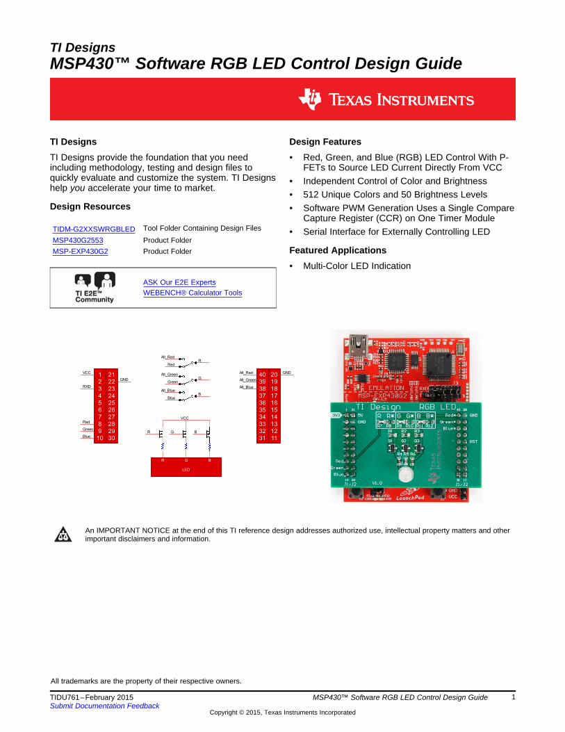
1.1 MSP430G2553The Texas Instruments™ MSP430G2553 is an ultra-low-power microcontroller from the MSP430 family ofdevices. Combined with extensive low-power modes, the architecture is optimized to achieve extendedbattery life in portable applications. The device features a powerful 16-bit RISC CPU, 16-bit registers, andmixed signal integration.
Devices in the MSP430G2xx3 family have two 16-bit timers, an optional 10-bit ADC with eight inputchannels (G2x53 devices), one universal serial communications interface (USCI), a comparator, and up to24 I/O pins. This reference design uses the MSP430G2553 in the MSP-EXP430G2 LaunchPad™, whichis the superset of the G2xx3 family of devices, with 16KB flash, 512 bytes RAM, and 16 I/Os in a DIPpackage.
Figure 1. MSP430G2553 Functional Block Diagram
2 MSP430™ Software RGB LED Control Design Guide TIDU761–February 2015Submit Documentation Feedback
Copyright © 2015, Texas Instruments Incorporated
www.ti.com Block Diagram
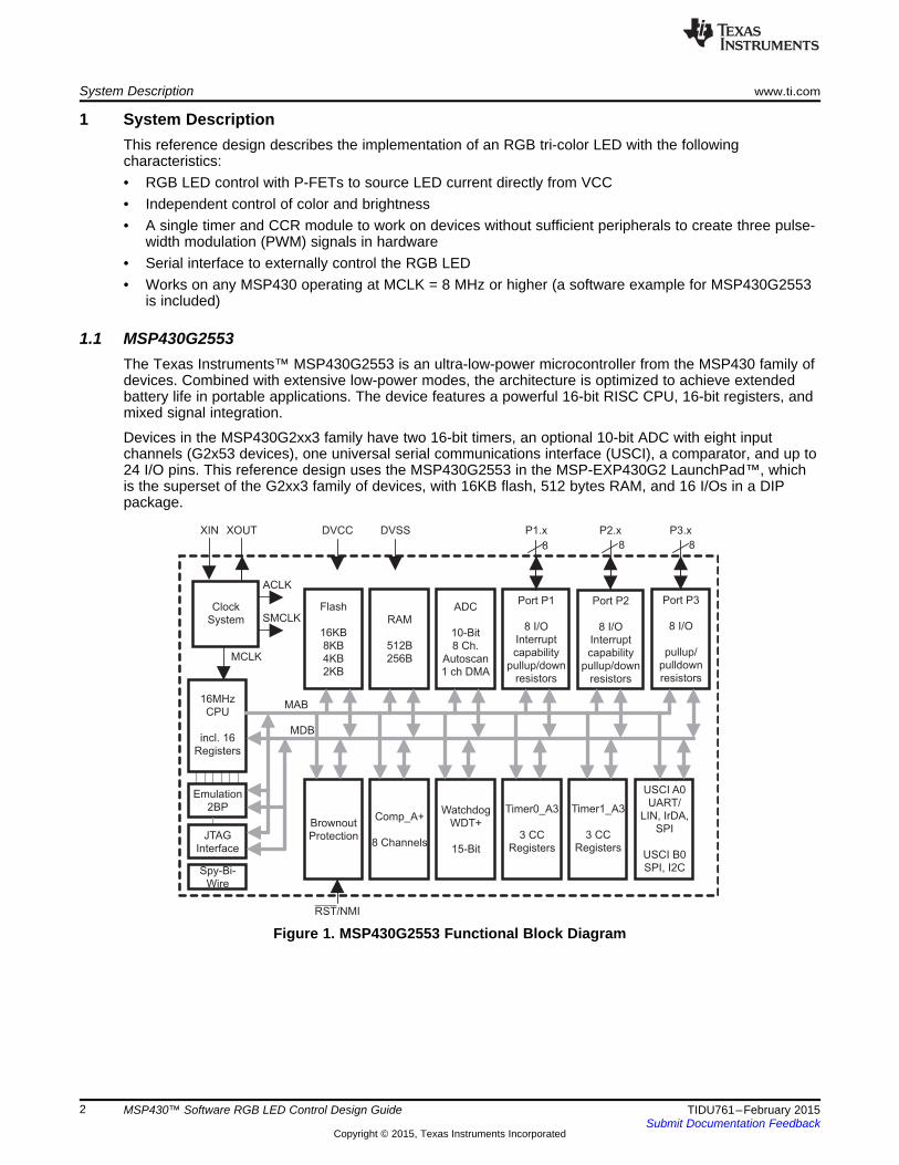
2 Block DiagramFigure 2 shows the block diagram for the BoosterPack™ version of this design. The three-color PWM pinshave alternate pin locations on the 40-pin BoosterPack connector. These locations are denoted with an *on the BoosterPack and "Alt" in the following block diagram.
Figure 2. System Block Diagram
3TIDU761–February 2015 MSP430™ Software RGB LED Control Design GuideSubmit Documentation Feedback
Copyright © 2015, Texas Instruments Incorporated
System Design Theory www.ti.com
3 System Design Theory
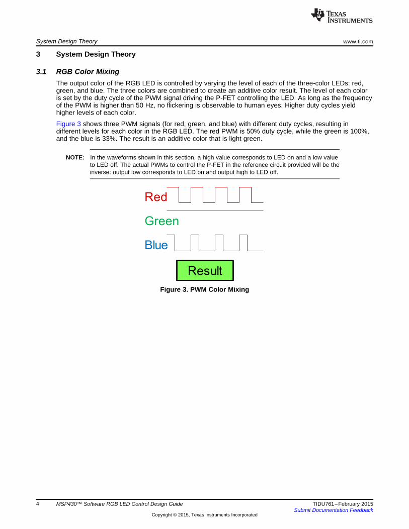
3.1 RGB Color MixingThe output color of the RGB LED is controlled by varying the level of each of the three-color LEDs: red,green, and blue. The three colors are combined to create an additive color result. The level of each coloris set by the duty cycle of the PWM signal driving the P-FET controlling the LED. As long as the frequencyof the PWM is higher than 50 Hz, no flickering is observable to human eyes. Higher duty cycles yieldhigher levels of each color.
Figure 3 shows three PWM signals (for red, green, and blue) with different duty cycles, resulting indifferent levels for each color in the RGB LED. The red PWM is 50% duty cycle, while the green is 100%,and the blue is 33%. The result is an additive color that is light green.
NOTE: In the waveforms shown in this section, a high value corresponds to LED on and a low valueto LED off. The actual PWMs to control the P-FET in the reference circuit provided will be theinverse: output low corresponds to LED on and output high to LED off.
Figure 3. PWM Color Mixing
4 MSP430™ Software RGB LED Control Design Guide TIDU761–February 2015Submit Documentation Feedback
Copyright © 2015, Texas Instruments Incorporated
www.ti.com System Design Theory
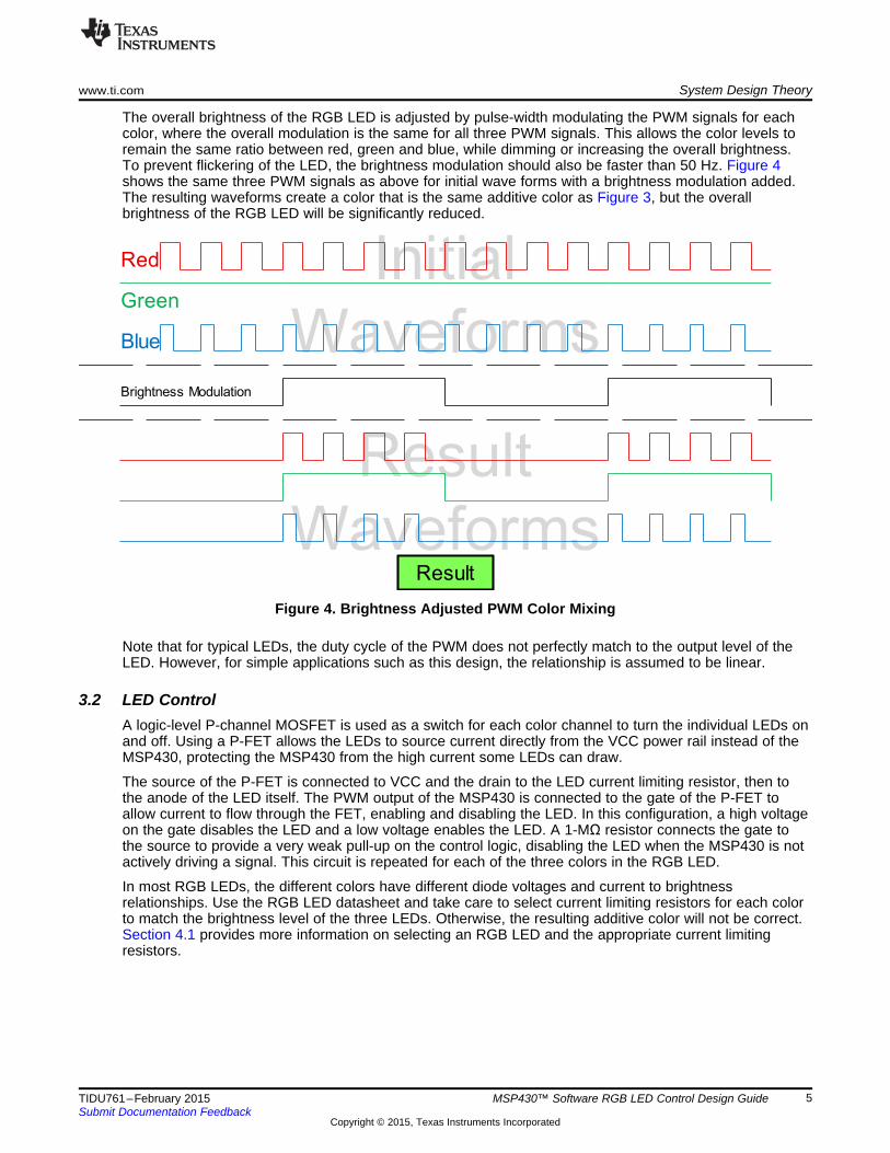
The overall brightness of the RGB LED is adjusted by pulse-width modulating the PWM signals for eachcolor, where the overall modulation is the same for all three PWM signals. This allows the color levels toremain the same ratio between red, green and blue, while dimming or increasing the overall brightness.To prevent flickering of the LED, the brightness modulation should also be faster than 50 Hz. Figure 4shows the same three PWM signals as above for initial wave forms with a brightness modulation added.The resulting waveforms create a color that is the same additive color as Figure 3, but the overallbrightness of the RGB LED will be significantly reduced.
Figure 4. Brightness Adjusted PWM Color Mixing
Note that for typical LEDs, the duty cycle of the PWM does not perfectly match to the output level of theLED. However, for simple applications such as this design, the relationship is assumed to be linear.
3.2 LED ControlA logic-level P-channel MOSFET is used as a switch for each color channel to turn the individual LEDs onand off. Using a P-FET allows the LEDs to source current directly from the VCC power rail instead of theMSP430, protecting the MSP430 from the high current some LEDs can draw.
The source of the P-FET is connected to VCC and the drain to the LED current limiting resistor, then tothe anode of the LED itself. The PWM output of the MSP430 is connected to the gate of the P-FET toallow current to flow through the FET, enabling and disabling the LED. In this configuration, a high voltageon the gate disables the LED and a low voltage enables the LED. A 1-MΩ resistor connects the gate tothe source to provide a very weak pull-up on the control logic, disabling the LED when the MSP430 is notactively driving a signal. This circuit is repeated for each of the three colors in the RGB LED.
In most RGB LEDs, the different colors have different diode voltages and current to brightnessrelationships. Use the RGB LED datasheet and take care to select current limiting resistors for each colorto match the brightness level of the three LEDs. Otherwise, the resulting additive color will not be correct.Section 4.1 provides more information on selecting an RGB LED and the appropriate current limitingresistors.
5TIDU761–February 2015 MSP430™ Software RGB LED Control Design GuideSubmit Documentation Feedback
Copyright © 2015, Texas Instruments Incorporated
L=0B=0
L=1B=0
L=2B=0
L=3B=0
L=1B=1
L=5B=0
L=4B=0
L=0B=1
L=0B
=2
L=0B
=3
L=0B
=4
L=0B
=5
L=0B
=6
L=0B
=7
L=0B
=0
L=0B
=1
L=0B
=2
L=0B
=3
System Design Theory www.ti.com
3.3 Creating PWMs in SoftwareCreating three PWMs on a device without sufficient timer CCR registers to create hardware PWMs (suchas many smaller MSP430s) can be done using a software PWM algorithm. Traditionally, software PWMsare created using a software counter that increments at a constant frequency and toggling a GPIO pin attwo-count values, resetting the counter at the higher value. Changing the smaller value (relative to thelarger) changes the duty cycle of the PWM and changing the larger value changes the frequency of thePWM. Additional PWMs can be created of the same frequency by comparing the count to additionalsmaller values to toggle different GPIO pins. When the counter is reset, all the PWM GPIO pins used aretoggled.
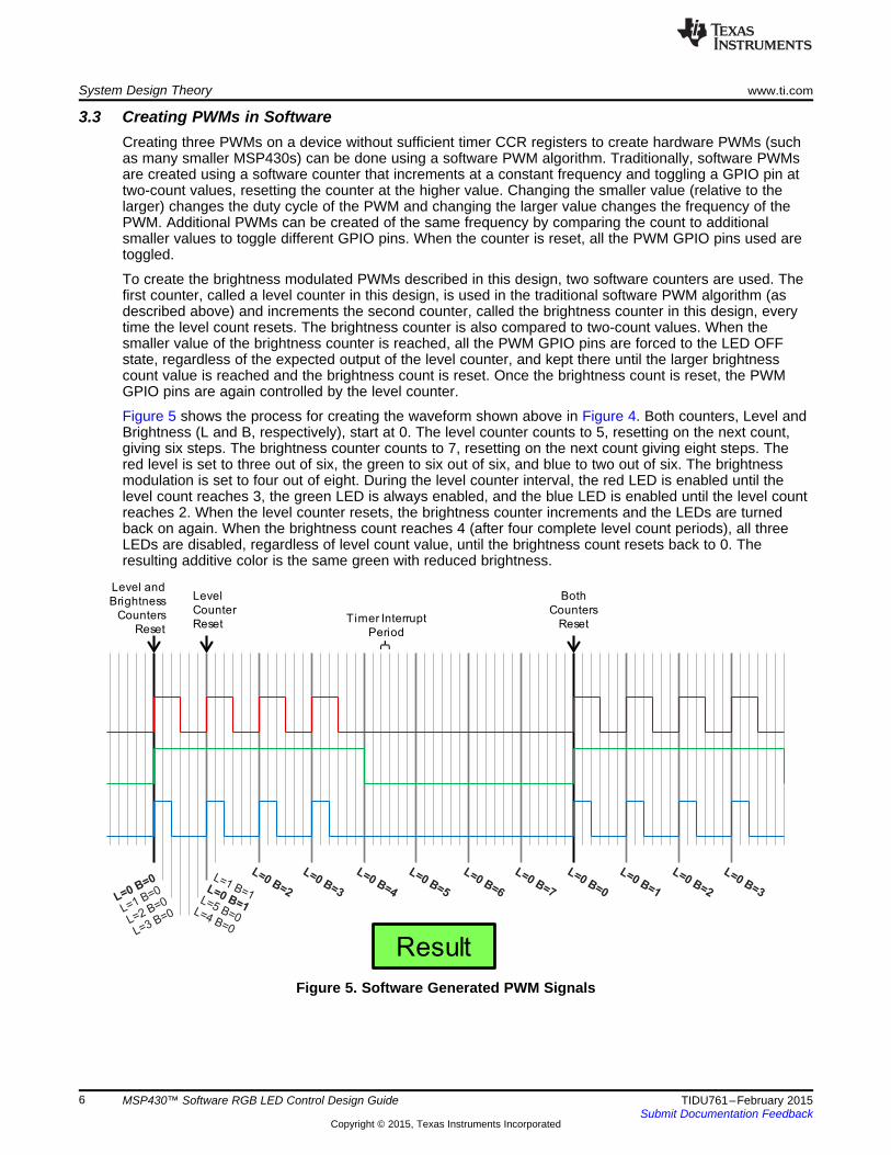
To create the brightness modulated PWMs described in this design, two software counters are used. Thefirst counter, called a level counter in this design, is used in the traditional software PWM algorithm (asdescribed above) and increments the second counter, called the brightness counter in this design, everytime the level count resets. The brightness counter is also compared to two-count values. When thesmaller value of the brightness counter is reached, all the PWM GPIO pins are forced to the LED OFFstate, regardless of the expected output of the level counter, and kept there until the larger brightnesscount value is reached and the brightness count is reset. Once the brightness count is reset, the PWMGPIO pins are again controlled by the level counter.
Figure 5 shows the process for creating the waveform shown above in Figure 4. Both counters, Level andBrightness (L and B, respectively), start at 0. The level counter counts to 5, resetting on the next count,giving six steps. The brightness counter counts to 7, resetting on the next count giving eight steps. Thered level is set to three out of six, the green to six out of six, and blue to two out of six. The brightnessmodulation is set to four out of eight. During the level counter interval, the red LED is enabled until thelevel count reaches 3, the green LED is always enabled, and the blue LED is enabled until the level countreaches 2. When the level counter resets, the brightness counter increments and the LEDs are turnedback on again. When the brightness count reaches 4 (after four complete level count periods), all threeLEDs are disabled, regardless of level count value, until the brightness count resets back to 0. Theresulting additive color is the same green with reduced brightness.
Figure 5. Software Generated PWM Signals
6 MSP430™ Software RGB LED Control Design Guide TIDU761–February 2015Submit Documentation Feedback
Copyright © 2015, Texas Instruments Incorporated

www.ti.com System Design Theory
3.4 RGB LED EffectsRGB LED lighting effects can be implemented in software to enable shorter and fewer commands over theserial interface. This design contains the following implemented effects:• Fade the RGB LED from one brightness level to another at a specified rate while maintaining a
specified color• Continuously fade the RGB LED from one brightness level to another then back to the first level at a
specified rate while maintaining a specified color
Implementing the effects requires controlling the rate at which the RGB LED brightness level is changed.The software PWM algorithm includes a wake-up counter that can be used to wake up the MSP430 fromlow power mode after a specified number of timer interrupts. This counter allows the effects to beimplemented at the required timings.
3.5 Serial InterfaceA serial interface is included in the design to allow an external controller to send commands to theMSP430. The command packet structure is set up as follows:• One byte: Length — Total length of the packet, including the length byte• One byte: Command — Specifies which command is being sent• n bytes: Command Data — Any additional data required by the specific command
space
This design has the following commands implemented:• 0x00 — Stop an active command and turn off the RGB LED
– Length — 0x02– Command — 0x00– Command data:
• (none)• 0x01 — Set the RGB LED to a specific color and brightness
– Length — 0x06– Command — 0x01– Command data:
• Red level — (one byte)• Green level — (one byte)• Blue level — (one byte)• Brightness level — (one byte)
• 0x02 — Fade the RGB LED– Length — 0x09– Command — 0x02– Command data:
• Red level — (one byte)• Green level — (one byte)• Blue level — (one byte)• Initial brightness level — (one byte)• Final brightness level — (one byte)• Total time of effect (in ms) — (two bytes, MSB first)
7TIDU761–February 2015 MSP430™ Software RGB LED Control Design GuideSubmit Documentation Feedback
Copyright © 2015, Texas Instruments Incorporated

System Design Theory www.ti.com
• 0x03 — Continuously pulse the RGB LED– Length — 0x09– Command — 0x03– Command data:
• Red level — (one byte)• Green level — (one byte)• Blue level — (one byte)• Low brightness level — (one byte)• High brightness level — (one byte)• Total time of single pulse, low-to-high-to-low, (in ms) — (two bytes, MSB first)
space
For example, the following commands are decoded:• 0x06, 0x01, 0x08, 0x08, 0x00, 0x32
– 0x06 — The command packet is six bytes long.– 0x01 — Command: Set the RGB LED to a specific color and brightness.– 0x08 — Set the color level of Red to 8, which is maximum in this design.– 0x08 — Set the color level of Green to 8, which is maximum in this design.– 0x00 — Set the color level of Blue to 0, or off.– 0x32 — Set the brightness to 50 (0x32), which is maximum in this design.– The command sets the Red to full on, Green to full on, and Blue to off, creating a yellow additive
color. The brightness is set to full.• 0x09, 0x03, 0x08, 0x04, 0x00, 0x05, 0x2D, 0x07, 0xD0
– 0x09 — The command packet is nine bytes long.– 0x03 — Command: Continuously pulse the RGB LED.– 0x08 — Set the color level of Red to 8, which is maximum in this design.– 0x04 — Set the color level of Green to 4, which is 50% in this design.– 0x00 — Set the color level of Blue to 0, or off.– 0x05 — Set the low brightness level to 5, which is 10% in this design.– 0x2D — Set the high brightness level to 45, which is 90% in this design.– 0x07, 0xD0 — Set the time for one complete pulse to 0x07D0 ms (2000 ms)– The command sets the Red level to 100%, Green to 50%, and Blue to 0%, which creates an
orange additive color. Then pulse the LED between 10% and 90% brightness with a complete pulsetaking 2000 ms.
8 MSP430™ Software RGB LED Control Design Guide TIDU761–February 2015Submit Documentation Feedback
Copyright © 2015, Texas Instruments Incorporated

www.ti.com System Design Theory
3.6 Effects of Temperature DriftTemperature drift impacts two portions of this design: the clock system on the MSP430, and the draincurrent on the P-FET transistors.
In the MSP430, a change in temperature changes the output frequency of the DCO, which ultimatelysources the timer module used to create the three PWMs. However, because the PWMs are all sourcedfrom the same DCO module, any change in DCO frequency will impact all three PWMs the same. Thismeans the PWMs may slightly change in frequency as the DCO varies, but the duty cycle will alwaysremain the same. Because the duty cycle is stable across temperature, there is no variation in color outputdue to DCO variation.
In the P-FET transistors, an increase in temperature results in a slight increase in drain current. Theincrease is most noticeable during the triode range, when the gate-to-source voltage (VGS) is between thethreshold voltage (VT) and 0 V. In the saturation range, when VGS surpasses VT, the current also increasesbut to a lesser extent. Because logic-level P-FETs are used in this design and the PWM varies betweenVCC and GND, the P-FETs spend minimal time in the triode range and primarily stay in the saturation andoff ranges. This results in a slight increase in current as temperature increases and a decrease astemperature decreases. An increase in current causes the brightness of the LED to increase.
Ultimately, as temperature increases, the brightness of the RGB LED will increase slightly, and astemperature decreases, the brightness will decrease slightly. Using FETs with a more stable temperaturecoefficient will decrease the level of brightness change.
9TIDU761–February 2015 MSP430™ Software RGB LED Control Design GuideSubmit Documentation Feedback
Copyright © 2015, Texas Instruments Incorporated
Reset
Setup ClocksTurn off LEDsEnable UART
Configure Timer
Received Command?
Enter Low Power Mode
No
Set new R, G, B and Brightness
values
Set LED
Set new R, G, B values
Set Brightness to start level
Fade
Brightness = finish level?
Yes
Adjust Brightness towards finish level
Set delay amountEnter LPM
No
Set new R, G, B values
Set Brightness to min level
Pulse
Stop Received?
No
YesStop
Received?
Brightness = max level?
No
Adjust Brightness higher
Set delay amountEnter LPM
No
Stop Received?
Brightness = min level?
Adjust Brightness lower
Set delay amountEnter LPM
Yes
No
No
Yes
Yes
Yes
System Design Theory www.ti.com
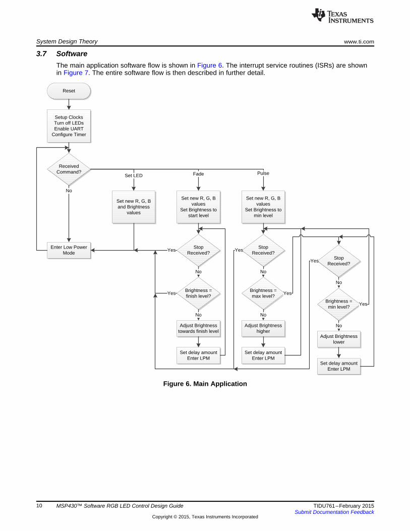
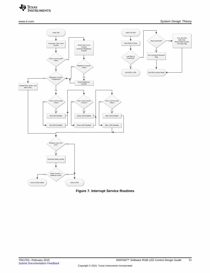
3.7 SoftwareThe main application software flow is shown in Figure 6. The interrupt service routines (ISRs) are shownin Figure 7. The entire software flow is then described in further detail.
Figure 6. Main Application
10 MSP430™ Software RGB LED Control Design Guide TIDU761–February 2015Submit Documentation Feedback
Copyright © 2015, Texas Instruments Incorporated
UART RX ISR
Save Byte to array
Last Byte of Command?
Exit ISR in LPM
No
Set Command Received FlagYes
Exit ISR to Active Mode
Timer ISR
Stop Command?
No
Turn off LEDsHalt Timer
Reset PWM CounterSet Stop Flag
Yes
Increment Color Level Counter
Color Level Counter = Max?
Reset Color Level Counter
Increment Brightness Counter
Yes
Brightness Counter = Max?
Reset Brightness Counter
YesBrightness Counter < Brightness?
No
Color Level Counter < Red?
Yes
Red LED Enabled
Yes
Red LED Disabled
NoColor Level Counter
< Green?
Green LED Enabled
Yes
Green LED Disabled
NoColor Level Counter
< Blue?
Blue LED Enabled
Yes
Blue LED Disabled
No
Disable Red, Green, and Blue LEDs
No
Increment delay counter
Delay Counter = Wakeup Count?
Exit to Active Mode Exit to LPM
Yes No
No
Wakeup count non-zero?
Yes
No
www.ti.com System Design Theory
Figure 7. Interrupt Service Routines
11TIDU761–February 2015 MSP430™ Software RGB LED Control Design GuideSubmit Documentation Feedback
Copyright © 2015, Texas Instruments Incorporated
System Design Theory www.ti.com
3.7.1 Main ApplicationIn the initialization routine, all the MSP430 pins are configured and unused pins are configured for thelowest power consumption. Next, the calibrated 8-MHz DCO values are loaded to the DCO controlregisters. The USCI module is configured for UART mode at 9600 8-N-1 mode. Timer_A0 is configured togive an interrupt every 200 clock cycles (25 μs at 8 MHz) but kept in Stop mode. The maximum value forthe color level counter is set to 8 and the maximum for the brightness counter is set to 50. This provides a9-bit color resolution (three bits per color), which is 512 unique colors. The overall refresh rate of the LEDPWM signals is 100 Hz (1 / (25 μs × 8 × 50) = 1/10 ms).
The main loop checks to see if a complete command has been received. If there is no command, thedevice enters low power mode. If a complete command was received, the command is executed asdescribed below. All commands start with resetting the RGB color levels, both the color level count andthe brightness level count, and the wake-up counter. The LEDs are also disabled, and the timer is reset.
Set LEDFor the Set LED command, the new values for the RGB and brightness levels are set. Then, the deviceenters low power mode. The timer interrupt will generate the correct waveforms to output the new color.
Fade LEDFor the Fade LED command, the new levels for RGB are set, along with the initial brightness level. Thewake-up count is calculated to determine how long to wait before adjusting the brightness to the next levelas part of the effect. The MSP430 enters low power mode to allow the timer interrupt to draw the color atthe current brightness level. After the determined number of timer interrupts has passed, the timer ISRexits to active mode. The brightness level is adjusted towards the final level, and the MSP430 is put backinto low power mode to repeat the cycle. When the brightness reaches the final level, the Fade subroutineexits and returns to the main loop, re-entering low power mode to await the next serial command. TheRGB LED stays configured at the final brightness level.
Pulse LEDFor the Pulse command, the new levels for RGB are set, along with the initial brightness level, which isthe lower brightness of the two levels specified in the command. The wake-up count is calculated todetermine how long to wait before increasing the brightness to the next level as part of the effect. TheMSP430 enters low power mode to allow the timer interrupt to draw the color at the appropriate brightnesslevel. After the determined number of timer interrupts has passed, the timer ISR exits to active mode. Thebrightness level is adjusted towards the finish level, and the MSP430 is put back into low power mode torepeat the cycle. When the brightness reaches the highest level, the process repeats, decreasing thebrightness level at each step. Once the initial brightness level is reached, the entire procedure starts overto create a continuous pulsing of the LED brightness.
12 MSP430™ Software RGB LED Control Design Guide TIDU761–February 2015Submit Documentation Feedback
Copyright © 2015, Texas Instruments Incorporated

www.ti.com System Design Theory
3.8 Timer ISRThe timer interrupt service routine creates the three color PWMs. First, the color level counter isincremented. If the max color level of 8 is reached, the color level counter is reset to 0 and the brightnesscounter is incremented. If the max brightness level of 50 is reached, the brightness counter is also reset to0. The brightness counter is compared to the global brightness level variable. If the counter is higher thanthe global variable, all three PWMs are set to disable the LED, output high in this design. Otherwise, thecolor level counter is compared to each color’s global variable for level. If the global variable is higher thanthe color level counter, that color’s PWM is set to enable the LED, output low in this design. If the colorlevel counter is higher than the global variable, the LED is disabled, output high in this design.
After all three PWMs have been updated based on the color level and brightness counters, if the wake-upcount is active (non-zero), the delay counter is incremented. If the delay counter does not match thespecified wake-up count, or the wake-up count is non-active, the ISR exits back to low power mode. If thedelay counter matches the wake-up count, the ISR exits to active mode, returning to the main loop.
3.9 UART ISRThe UART RX ISR saves each incoming byte to an array. The first byte in the command packet is thenumber of bytes in the command. This command length byte is used to determine when the entirecommand has been received. If the command is a Stop command, the ISR disables the LEDs by settingthe three PWMs to output high, halts the timer, resets the counters, and sets the global stop flag. The ISRthen exits to active mode where any active effect will see the stop flag and exit back to the main loopwaiting for a new command. If the command is not a Stop command, the ISR sets the global commandreceived flag and exits to active mode. The main loop then executes the command.
13TIDU761–February 2015 MSP430™ Software RGB LED Control Design GuideSubmit Documentation Feedback
Copyright © 2015, Texas Instruments Incorporated

Getting Started: Hardware www.ti.com
4 Getting Started: Hardware
4.1 Picking an RGB LED and Current Limiting ResistorsThis reference design uses an RGB LED with a common cathode. The anodes of the three LEDs areconnected to VCC through a current limiting resistor and a P-FET for controlling each color. Any RGB LEDcan be used, but if N-FETs are used to control each color, the PWM signals should be inverted from whatis implemented in this design. Also, some RGB LEDs have diffusers built into the packaging and some donot. Use a diffuser, either built into the LED or added externally, to fully blend the three colors into theresulting additive color.
The current limiting resistors should be picked for each color in the RGB LED so that all three color outputlevels are balanced. Failure to balance the colors will result in incorrect additive colors on the LED duringoperation. The datasheet for the RGB LED used provides a current-versus-brightness graph for eachcolor. Use current limiting resistors to set the current for each color that result in comparable brightness.To verify that the resistors picked are correct, set the design to output white (RGB levels all set to thesame value) and verify the additive color created by the LED is white.
4.2 Obtaining a PCBAs RGB LEDs vary in size, footprint, and configuration, the hardware for this design is not available toorder. The design files for the schematic and PCB are available at http://www.ti.com/tool/TIDM-G2XXSWRGBLED and can be modified to create the correct circuit for the RGB LED used. Alternatively,because the circuit for controlling an RGB LED is very basic, a prototype can be easily built using abreadboard or similar method.
This design also includes the required Gerber files and BOM to build the exact PCB shown in the guide.
14 MSP430™ Software RGB LED Control Design Guide TIDU761–February 2015Submit Documentation Feedback
Copyright © 2015, Texas Instruments Incorporated
www.ti.com Getting Started: Hardware
4.3 Connecting to the LaunchPadTI LaunchPads are low cost, easy to use, development kits with common header connections to connectBoosterPacks. BoosterPacks are plug-in modules that connect to LaunchPads to enable additionalapplications. This design follows the 40-pin BoosterPack pinout standard as shown on the LaunchPadBuild Your Own BoosterPack page to enable compatibility with the MSP-EXP430G2 LaunchPad. TheMSP-EXP430G2 LaunchPad is available to purchase at the TI Store.
The procedure for connecting the design to the LaunchPad for both the BoosterPack and breadboardversions are shown in the following sections.
4.3.1 BoosterPack VersionThe RGB LED BoosterPack described in this design was tested with the MSP-EXP430G2 Rev 1.5LaunchPad. Other LaunchPad revisions might contain differences and should be compared to Rev 1.5 todetermine if any changes will cause problems. The MSP-EXP430G2 User’s Guide contains revisioninformation that can be used to help reconcile these changes as necessary. [1]
When plugging the RGB BoosterPack into the MSP-EXP430G2 LaunchPad, ensure the 3V3 pin on theBoosterPack header aligns with the VCC pin on the LaunchPad and the GND pin on the BoosterPack withthe top right GND pin on the LaunchPad.
There are two source pins for each color PWM on the BoosterPack to allow different GPIOs on theMSP430 to source the PWMs depending on the requirements of the design. On the PCB, there is a pair of0-Ω resistors for each PWM. One 0-Ω resistor should be populated to select the source pin for the PWM,and the other should be left non-populated. The primary PWM pins are on the outer rows of the 40-pinBoosterPack connector and the alternate pins (marked with an * on the PCB) are on the inner rows of theBoosterPack connector.
The RGB LED BoosterPack uses the following pins on the MSP-EXP430G2 LaunchPad:• P1.1 — UART RX: Receive pin for serial communication• P2.0 — Red PWM: PWM output from MSP430 for controlling the red LED• P2.1 — Green PWM: PWM output from MSP430 for controlling the green LED• P2.2 — Blue PWM: PWM output from MSP430 for controlling the blue LED
4.3.2 Breadboard Prototype VersionBuilding the RGB LED circuit without the BoosterPack is simple to do with a bread board or similarprototyping mechanism. The LED driving circuit shown in this design (or similar, depending on the RGBLED used) should be built on the breadboard. Jumper wires can be used to connect VCC, Ground, andthe three PWMs (red, green, and blue) from the LaunchPad to the breadboard. The default pins for RGBare P2.0, P2.1, and P2.2, respectively.
4.4 Connecting Serial InterfaceThe UART interface to the MSP430 uses P1.1, configured as UCA0RXD, UART Receiver. The UARTtransmit pin is not used in this design. The back channel UART in the LaunchPad provides a simplemechanism for communicating with this design through UART. To use the back channel UART, connectthe UART jumpers on J3 of the LaunchPad in the hardware mode (see MSP-EXP430G2 User’s Guide formore information [1]). Only the top jumper is required for MSP430 RX. To use another UART device tosend commands to the MSP430, disconnect the UART jumpers on the LaunchPad and connect the UARThost transmit pin to the RXD pin on the BoosterPack.
15TIDU761–February 2015 MSP430™ Software RGB LED Control Design GuideSubmit Documentation Feedback
Copyright © 2015, Texas Instruments Incorporated
Getting Started: Firmware www.ti.com
5 Getting Started: FirmwareThe project included in the software package has been built and tested with CCS 6.0.0.00190 usingcompiler version TI v4.3.1. The download package includes a single code file, G2xx_RGB_LED.c, whichshould be included into a new CCS project for building.
The procedure to build the project for CCS is described in the following section.
5.1 Building Using CCS v6
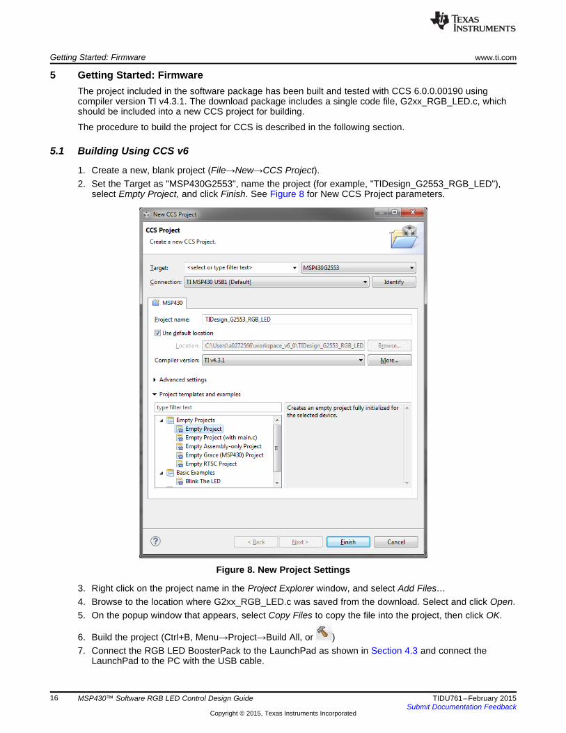
1. Create a new, blank project (File→New→CCS Project).2. Set the Target as "MSP430G2553", name the project (for example, "TIDesign_G2553_RGB_LED"),
select Empty Project, and click Finish. See Figure 8 for New CCS Project parameters.
Figure 8. New Project Settings
3. Right click on the project name in the Project Explorer window, and select Add Files…4. Browse to the location where G2xx_RGB_LED.c was saved from the download. Select and click Open.5. On the popup window that appears, select Copy Files to copy the file into the project, then click OK.
6. Build the project (Ctrl+B, Menu→Project→Build All, or )7. Connect the RGB LED BoosterPack to the LaunchPad as shown in Section 4.3 and connect the
LaunchPad to the PC with the USB cable.
16 MSP430™ Software RGB LED Control Design Guide TIDU761–February 2015Submit Documentation Feedback
Copyright © 2015, Texas Instruments Incorporated
#define DEMO_MODE
www.ti.com Getting Started: Firmware
8. Download project to device (F11, Menu→Run→Debug, or )
9. Execute the program ( ) or close debugger and reset device.
5.2 RGB LED Demo ModeThis design also includes a demo mode in the firmware to demonstrate the RGB LED control without theneed for a serial command. To run the demo mode version of the software, the lineof code at the beginning of the G2xx_RGB_LED.c file should be uncommented. Then rebuild, download,and execute the project as shown in Steps 6 through 9 in Section 5.1.
5.3 PC Serial Interface through LaunchPad Back Channel UARTA PC serial terminal application can be used to send commands to the design using the LaunchPad’sback channel UART. To match the command protocol for this design, it is important to use a serialterminal that allows sending raw hex values instead of ASCII characters.
17TIDU761–February 2015 MSP430™ Software RGB LED Control Design GuideSubmit Documentation Feedback
Copyright © 2015, Texas Instruments Incorporated
Customizing the RGB LED www.ti.com
6 Customizing the RGB LED
6.1 RGB LEDAs mentioned in Section 4.1, the RGB LED in the design can be swapped out for a different model.Because there could be differences in footprint or configuration, the circuitry for the drive circuit may needto be changed as well. If N-FETs are used instead of P-FETs to enable the three-color LEDs, the output ofthe PWMs should be inverted as well.
6.2 Changing GPIOs Used for PWMsAny GPIO can be used to generate the three PWMs for red, green, and blue. The timer ISR should bemodified to use the appropriate GPIOs for generating the PWM. Using the same GPIO port for all threePWMs and using sequential bits in the same port (that is, P2.0, P2.1, and P2.2) will reduce the instructioncount for the software required to generate the PWM. Also, using the lower bits (P2.0, P2.1, and P2.2) willbe more efficient than the higher bits (P2.7, P2.6, and P2.5). The software takes advantage ofcomparisons in C returning 0x00 or 0x01 with fewer shift instructions required to put the correct value inthe correct bit of the port.
18 MSP430™ Software RGB LED Control Design Guide TIDU761–February 2015Submit Documentation Feedback
Copyright © 2015, Texas Instruments Incorporated
while(1) switch (uartRxBuffer[1])
www.ti.com Customizing the RGB LED
6.3 Application
6.3.1 MCU System InitializationThe software included in this reference design initializes the MCU system and peripherals as follows:• Watchdog disabled• MCLK = SMCLK = DCO = 8 MHz from calibration constants in info memory• ACLK = unused• Unused GPIOs are set to output low
6.3.2 Changing RGB LED PWM ConfigurationThe RGB LED PWMs must have an overall refresh rate greater than 50 Hz or flickering will be observable.The eight color levels and 50 brightness levels in this design were used with a 25-μs step generated bythe Timer_A0 module to create a 100-Hz overall refresh rate. Both the color level and brightness levelscan be adjusted, as well as the timer step size to create custom color and brightness resolutions to matchthe specific system requirements. For example, if more color resolution but less brightness resolution isneeded, a possible configuration would be 64 color levels, 10 brightness levels, and a 25-μs step size,resulting in a refresh rate of 62.5 Hz. The limit to how small the time steps can be is determined by thenumber of clock cycles required to execute the timer ISR to create the PWMs.
6.3.3 Adding EffectsThe MSP430 can implement light effects using the RGB LED, such as the Fade and Pulse effects alreadyimplemented. Additional effects can be added by creating new functions to perform the new effects. Thesefunctions should utilize the delay counter, counting the number of timer ISRs, as the timing mechanism forcreating the required timings of the effects.
Each effect added that uses the delay timer should also enable the Stop command to exit the effectfunction. The effect loop should check the status of the exitRoutine flag, which is set when a Stopcommand is received, and correctly exit out of the effect function, returning to the main loop to wait for anew command.
6.3.4 Adding Serial CommandsAs new effects are added, the MSP430 should also support additional serial commands to enable usingthese effects. The serial command protocol described in Section 3.5 allows for a total of 256 uniquecommands, including the four commands already in the example, and should be used for addingadditional commands.
In the main loop of the main function, there is a switch statement, ,that determines which serial command has been received and starts executing the appropriate effect.Adding handling for additional commands is done by creating new cases in the switch statement for thenew command. As described in Section 6.3.3, new effects should be implemented using new functions.The new case state in the main loop should only call the function for the new effect. This allows theimplemented Stop command to execute correctly.
19TIDU761–February 2015 MSP430™ Software RGB LED Control Design GuideSubmit Documentation Feedback
Copyright © 2015, Texas Instruments Incorporated
Test Data www.ti.com
7 Test Data
7.1 Power ConsumptionThere are three operation modes for the MSP430 in this design:1. LED inactive, waiting for serial command2. LED active and enabled3. LED active and disabled
In the two modes during which the LED is active, the time the MSP430 spends in active mode changesdepending on the brightness count versus the brightness level. When the brightness count is greater thanthe brightness level, all LEDs are disabled, which is handled in significantly fewer instructions, resulting inmore time spent in low power mode and, therefore, less average current.
All current data shown does not account for the current of the LED, which will vary significantly based onwhich RGB LED is used and the drive circuitry for the LED.
To get a complete current profile for a design, consider the percentage of time the design spends in eachof the three modes. To verify the calculated power profile, disconnect the VCC jumper, J3 on the MSP-EXP430G2 LaunchPad and connect an ammeter in series. To remove the impact of the RGB LED drivecircuitry on the measurement, remove the BoosterPack before measuring the current.
7.1.1 Power Consumption — LED Inactive, Waiting for CommandWhen the RGB LED is inactive, the timer interrupts are disabled and the MSP430 remains in LPM0without waking up, waiting for UART data on the USCI module. The MSP430 must stay in LPM0 to keepthe clock system powered because the UART uses SMCLK to generate a stable baud rate clock. The totalcurrent is the datasheet value for LPM0, 56 µA at 2.2 V.
20 MSP430™ Software RGB LED Control Design Guide TIDU761–February 2015Submit Documentation Feedback
Copyright © 2015, Texas Instruments Incorporated
www.ti.com Test Data
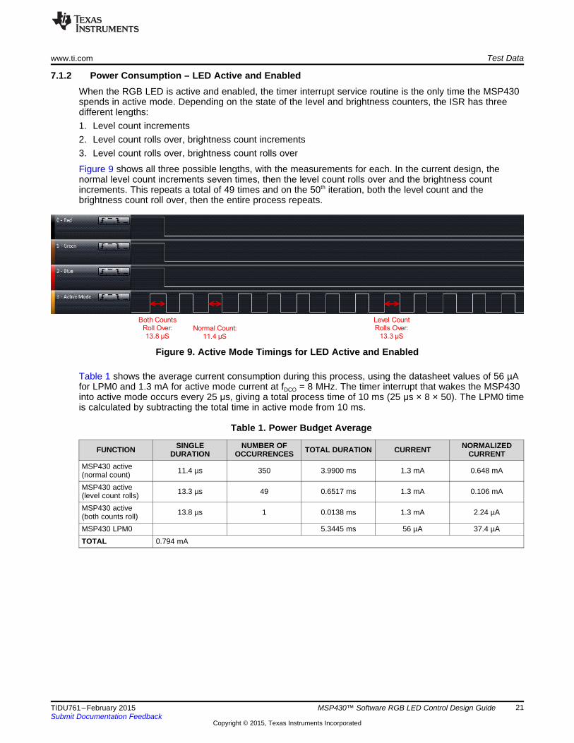
7.1.2 Power Consumption – LED Active and EnabledWhen the RGB LED is active and enabled, the timer interrupt service routine is the only time the MSP430spends in active mode. Depending on the state of the level and brightness counters, the ISR has threedifferent lengths:1. Level count increments2. Level count rolls over, brightness count increments3. Level count rolls over, brightness count rolls over
Figure 9 shows all three possible lengths, with the measurements for each. In the current design, thenormal level count increments seven times, then the level count rolls over and the brightness countincrements. This repeats a total of 49 times and on the 50th iteration, both the level count and thebrightness count roll over, then the entire process repeats.
Figure 9. Active Mode Timings for LED Active and Enabled
Table 1 shows the average current consumption during this process, using the datasheet values of 56 µAfor LPM0 and 1.3 mA for active mode current at fDCO = 8 MHz. The timer interrupt that wakes the MSP430into active mode occurs every 25 μs, giving a total process time of 10 ms (25 μs × 8 × 50). The LPM0 timeis calculated by subtracting the total time in active mode from 10 ms.
Table 1. Power Budget Average
SINGLE NUMBER OF NORMALIZEDFUNCTION TOTAL DURATION CURRENTDURATION OCCURRENCES CURRENTMSP430 active 11.4 µs 350 3.9900 ms 1.3 mA 0.648 mA(normal count)MSP430 active 13.3 µs 49 0.6517 ms 1.3 mA 0.106 mA(level count rolls)MSP430 active 13.8 µs 1 0.0138 ms 1.3 mA 2.24 µA(both counts roll)MSP430 LPM0 5.3445 ms 56 µA 37.4 µATOTAL 0.794 mA
21TIDU761–February 2015 MSP430™ Software RGB LED Control Design GuideSubmit Documentation Feedback
Copyright © 2015, Texas Instruments Incorporated
Test Data www.ti.com
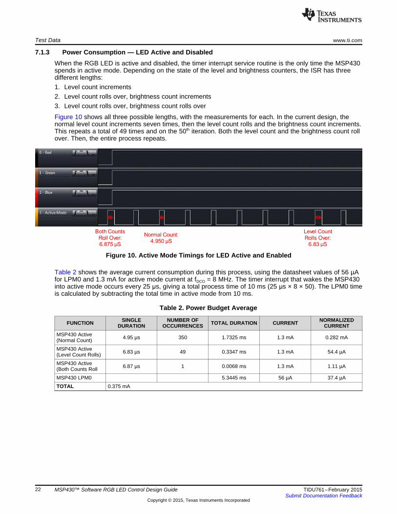
7.1.3 Power Consumption — LED Active and DisabledWhen the RGB LED is active and disabled, the timer interrupt service routine is the only time the MSP430spends in active mode. Depending on the state of the level and brightness counters, the ISR has threedifferent lengths:1. Level count increments2. Level count rolls over, brightness count increments3. Level count rolls over, brightness count rolls over
Figure 10 shows all three possible lengths, with the measurements for each. In the current design, thenormal level count increments seven times, then the level count rolls and the brightness count increments.This repeats a total of 49 times and on the 50th iteration. Both the level count and the brightness count rollover. Then, the entire process repeats.
Figure 10. Active Mode Timings for LED Active and Enabled
Table 2 shows the average current consumption during this process, using the datasheet values of 56 µAfor LPM0 and 1.3 mA for active mode current at fDCO = 8 MHz. The timer interrupt that wakes the MSP430into active mode occurs every 25 μs, giving a total process time of 10 ms (25 μs × 8 × 50). The LPM0 timeis calculated by subtracting the total time in active mode from 10 ms.
Table 2. Power Budget Average
SINGLE NUMBER OF NORMALIZEDFUNCTION TOTAL DURATION CURRENTDURATION OCCURRENCES CURRENTMSP430 Active 4.95 µs 350 1.7325 ms 1.3 mA 0.282 mA(Normal Count)MSP430 Active 6.83 µs 49 0.3347 ms 1.3 mA 54.4 µA(Level Count Rolls)MSP430 Active 6.87 µs 1 0.0068 ms 1.3 mA 1.11 µA(Both Counts RollMSP430 LPM0 5.3445 ms 56 µA 37.4 µATOTAL 0.375 mA
22 MSP430™ Software RGB LED Control Design Guide TIDU761–February 2015Submit Documentation Feedback
Copyright © 2015, Texas Instruments Incorporated
www.ti.com Design Files
8 Design Files
8.1 SchematicsTo download the most recent schematics, see the design files at TIDM-G2XXSWRGBLED.
8.2 Bill of MaterialsTo download the most recent bill of materials (BOM), see the design files at TIDM-G2XXSWRGBLED.
8.3 Layer PlotsTo download the most recent layer plots, see the design files at TIDM-G2XXSWRGBLED.
8.4 Altium ProjectTo download the most recent Altium project files, see the design files at TIDM-G2XXSWRGBLED.
8.5 Gerber FilesTo download the most recent Gerber files, see the design files at TIDM-G2XXSWRGBLED.
8.6 Assembly DrawingsTo download the most recent assembly drawings, see the design files at TIDM-G2XXSWRGBLED.
8.7 Software FilesTo download the most recent software files, see the design files at TIDM-G2XXSWRGBLED.
9 References
1. Texas Instruments, MSP430x2xx Family User’s Guide (SLAU144)2. Texas Instruments, MSP-EXP430G2 LaunchPad Evaluation Kit User's Guide (SLAU318)3. Texas Instruments, Build Your Own Boosterpack (www.ti.com/byob)
10 About the AuthorMIKE PRIDGEN is an applications engineer on the MSP430 Customer Applications Team at TexasInstruments. Pridgen joined TI in 2012 into the Digital LEAP Program where he rotated through variousbusiness groups and expand his knowledge across several TI products. He has focused on the MSP430ultra-low-power microcontroller family with specialization in direct customer support for MSP430G2xxdevices.
23TIDU761–February 2015 MSP430™ Software RGB LED Control Design GuideSubmit Documentation Feedback
Copyright © 2015, Texas Instruments Incorporated

IMPORTANT NOTICE FOR TI REFERENCE DESIGNS
Texas Instruments Incorporated ("TI") reference designs are solely intended to assist designers (“Buyers”) who are developing systems thatincorporate TI semiconductor products (also referred to herein as “components”). Buyer understands and agrees that Buyer remainsresponsible for using its independent analysis, evaluation and judgment in designing Buyer’s systems and products.TI reference designs have been created using standard laboratory conditions and engineering practices. TI has not conducted anytesting other than that specifically described in the published documentation for a particular reference design. TI may makecorrections, enhancements, improvements and other changes to its reference designs.Buyers are authorized to use TI reference designs with the TI component(s) identified in each particular reference design and to modify thereference design in the development of their end products. HOWEVER, NO OTHER LICENSE, EXPRESS OR IMPLIED, BY ESTOPPELOR OTHERWISE TO ANY OTHER TI INTELLECTUAL PROPERTY RIGHT, AND NO LICENSE TO ANY THIRD PARTY TECHNOLOGYOR INTELLECTUAL PROPERTY RIGHT, IS GRANTED HEREIN, including but not limited to any patent right, copyright, mask work right,or other intellectual property right relating to any combination, machine, or process in which TI components or services are used.Information published by TI regarding third-party products or services does not constitute a license to use such products or services, or awarranty or endorsement thereof. Use of such information may require a license from a third party under the patents or other intellectualproperty of the third party, or a license from TI under the patents or other intellectual property of TI.TI REFERENCE DESIGNS ARE PROVIDED "AS IS". TI MAKES NO WARRANTIES OR REPRESENTATIONS WITH REGARD TO THEREFERENCE DESIGNS OR USE OF THE REFERENCE DESIGNS, EXPRESS, IMPLIED OR STATUTORY, INCLUDING ACCURACY ORCOMPLETENESS. TI DISCLAIMS ANY WARRANTY OF TITLE AND ANY IMPLIED WARRANTIES OF MERCHANTABILITY, FITNESSFOR A PARTICULAR PURPOSE, QUIET ENJOYMENT, QUIET POSSESSION, AND NON-INFRINGEMENT OF ANY THIRD PARTYINTELLECTUAL PROPERTY RIGHTS WITH REGARD TO TI REFERENCE DESIGNS OR USE THEREOF. TI SHALL NOT BE LIABLEFOR AND SHALL NOT DEFEND OR INDEMNIFY BUYERS AGAINST ANY THIRD PARTY INFRINGEMENT CLAIM THAT RELATES TOOR IS BASED ON A COMBINATION OF COMPONENTS PROVIDED IN A TI REFERENCE DESIGN. IN NO EVENT SHALL TI BELIABLE FOR ANY ACTUAL, SPECIAL, INCIDENTAL, CONSEQUENTIAL OR INDIRECT DAMAGES, HOWEVER CAUSED, ON ANYTHEORY OF LIABILITY AND WHETHER OR NOT TI HAS BEEN ADVISED OF THE POSSIBILITY OF SUCH DAMAGES, ARISING INANY WAY OUT OF TI REFERENCE DESIGNS OR BUYER’S USE OF TI REFERENCE DESIGNS.TI reserves the right to make corrections, enhancements, improvements and other changes to its semiconductor products and services perJESD46, latest issue, and to discontinue any product or service per JESD48, latest issue. Buyers should obtain the latest relevantinformation before placing orders and should verify that such information is current and complete. All semiconductor products are soldsubject to TI’s terms and conditions of sale supplied at the time of order acknowledgment.TI warrants performance of its components to the specifications applicable at the time of sale, in accordance with the warranty in TI’s termsand conditions of sale of semiconductor products. Testing and other quality control techniques for TI components are used to the extent TIdeems necessary to support this warranty. Except where mandated by applicable law, testing of all parameters of each component is notnecessarily performed.TI assumes no liability for applications assistance or the design of Buyers’ products. Buyers are responsible for their products andapplications using TI components. To minimize the risks associated with Buyers’ products and applications, Buyers should provideadequate design and operating safeguards.Reproduction of significant portions of TI information in TI data books, data sheets or reference designs is permissible only if reproduction iswithout alteration and is accompanied by all associated warranties, conditions, limitations, and notices. TI is not responsible or liable forsuch altered documentation. Information of third parties may be subject to additional restrictions.Buyer acknowledges and agrees that it is solely responsible for compliance with all legal, regulatory and safety-related requirementsconcerning its products, and any use of TI components in its applications, notwithstanding any applications-related information or supportthat may be provided by TI. Buyer represents and agrees that it has all the necessary expertise to create and implement safeguards thatanticipate dangerous failures, monitor failures and their consequences, lessen the likelihood of dangerous failures and take appropriateremedial actions. Buyer will fully indemnify TI and its representatives against any damages arising out of the use of any TI components inBuyer’s safety-critical applications.In some cases, TI components may be promoted specifically to facilitate safety-related applications. With such components, TI’s goal is tohelp enable customers to design and create their own end-product solutions that meet applicable functional safety standards andrequirements. Nonetheless, such components are subject to these terms.No TI components are authorized for use in FDA Class III (or similar life-critical medical equipment) unless authorized officers of the partieshave executed an agreement specifically governing such use.Only those TI components that TI has specifically designated as military grade or “enhanced plastic” are designed and intended for use inmilitary/aerospace applications or environments. Buyer acknowledges and agrees that any military or aerospace use of TI components thathave not been so designated is solely at Buyer's risk, and Buyer is solely responsible for compliance with all legal and regulatoryrequirements in connection with such use.TI has specifically designated certain components as meeting ISO/TS16949 requirements, mainly for automotive use. In any case of use ofnon-designated products, TI will not be responsible for any failure to meet ISO/TS16949.IMPORTANT NOTICE
Mailing Address: Texas Instruments, Post Office Box 655303, Dallas, Texas 75265Copyright © 2015, Texas Instruments Incorporated