Embed Size (px)
Citation preview
Application ReportSLAA529A–March 2012–Revised June 2012
MSP430™ Based Lithium-Ion Polymer Battery Chargingand Gauging Solution Using USB Power
Tyler Witt, Bhargavi Nisarga................................................................................... MSP430 Applications
ABSTRACT
The use of USB power to charge Lithium-Ion Polymer (LiPo) batteries in electronic systems and deviceshas become quite popular. To assist in the development of such circuitry in embedded systemapplications, this application report provides the details on the hardware and software requirementsneeded to not only implement a battery charging solution using the bq24230 battery charger and theMSP430™ USB device (in a switched context USB power configuration), but also to monitor the batterystatus using the bq27410 fuel gauge to read important battery statistics and status information.
The example cases discussed in this application report provide a basic understanding of what needs to bedone at production, as well as on the application level, to achieve the aforementioned goals. Theassociated software provides library functions to interface and communicate with the bq27410 fuel gauge,applicable to any USB-equipped MSP430 device. The software also includes a demo application thatintegrates the USB stacks and the fuel gauge library functions to read the battery information from the fuelgauge and transmit it to the PC through USB Communications Device Class (CDC).
Source files and other collateral that are discussed in this application report can be downloaded fromhttp://software-dl.ti.com/msp430/msp430_public_sw/mcu/msp430/MSP430_LIPO/latest/index_FDS.html.
Contents1 Introduction .................................................................................................................. 22 LiPo Battery Charging Solution Using MSP430 and bq24230 ........................................................ 23 MSP430-Based Fuel Gauging Using bq27410 ......................................................................... 44 MSP430 USB Operation ................................................................................................... 75 LiPo Battery Charging and Fuel Gauging Demo Application .......................................................... 96 References ................................................................................................................. 12Appendix A Associated Code Files ........................................................................................... 13Appendix B Demo Hardware Schematic ..................................................................................... 14
List of Figures
1 Block Diagram - Battery Charging Using MSP430 ..................................................................... 2
2 Block Diagram - MSP430-Based Fuel Gauging Using bq27410 ..................................................... 4
3 bq27410 Fuel Gauge - Flash Data Write Flow Chart .................................................................. 5
4 bq27410 Fuel Gauge - Flash Data Read Flow Chart .................................................................. 6
5 MSP430-Based Battery Charging and Gauging Demo - High-level Flow Chart .................................. 10
6 MSP430-Based Battery Charging and Gauging Demo - Detailed Flow Chart .................................... 11
7 MSP430-Based Battery Charging and Gauging Demo - HyperTerminal Screenshot ............................ 12
8 MSP430-Based Battery Charging and Gauging Demo Schematic ................................................. 14
List of Tables
1 bq24230 Battery Charger Configurations ................................................................................ 3
2 Charging Circuit - Power Numbers ....................................................................................... 3
3 USB Connection States and Operation .................................................................................. 9
1MSP430, Impedance Track are trademarks of Texas Instruments.2All other trademarks are the property of their respective owners.
1SLAA529A–March 2012–Revised June 2012 MSP430™ Based Lithium-Ion Polymer Battery Charging and GaugingSolution Using USB PowerSubmit Documentation Feedback
Copyright © 2012, Texas Instruments Incorporated

Introduction www.ti.com
4 Power Consumption....................................................................................................... 12
5 Associated Code Files .................................................................................................... 13
1 Introduction
This application report provides a complete solution for charging a LiPo battery through use of USBpower, interfaced with an MSP430F6638 (although any USB-equipped MSP430 device can be used), andmonitoring the battery using a bq27410 fuel gauge. The two main goals of this application report are:
• LiPo battery charging with USB power by a bq24230 battery charger
• Battery fuel gauging by a bq27410 fuel gauge
This application report describes the hardware chosen for this application, why it was chosen, and whatsoftware solutions are needed to most effectively achieve the goals. Power consumption numbers for eachdifferent component are also included, highlighting the system’s low-power requirements.
NOTE: A LiPo battery with 3.7-V nominal voltage and 300-mAh capacity is used for proof-of-concept and demonstration. [1]
2 LiPo Battery Charging Solution Using MSP430 and bq24230
This section explains in detail what hardware components are used for the battery charging circuitrysolution (see Figure 1) and why they are selected. It also reports the power measurements of each devicein the system.
Figure 1. Block Diagram - Battery Charging Using MSP430
See the hardware schematic connections in Appendix B.
2.1 bq24230 Battery Charger
The bq24230 is a low power Li-Ion battery charger and power-path management IC [2]. It automaticallyswitches the power source between USB power and battery power for supplying power to the MSP430and the rest of the system. Depending on if the CE (Charge Enable) pin on the bq24230 is low or high, thebattery charging by USB is enabled or disabled, respectively.
Both the USB power and battery are connected to the bq24230 battery charger. When the USB power isavailable, the charger uses the USB power to provide a regulated 4.4 V at the charger output, regardlessof the battery’s connection status. When USB power is not available, the bq24230 device supplies thebattery voltage at its output. Table 1 lists the various charger configurations.
2 MSP430™ Based Lithium-Ion Polymer Battery Charging and Gauging SLAA529A–March 2012–Revised June 2012Solution Using USB Power Submit Documentation Feedback
Copyright © 2012, Texas Instruments Incorporated

www.ti.com LiPo Battery Charging Solution Using MSP430 and bq24230
Table 1. bq24230 Battery Charger Configurations
Battery USB bq24230 bq24230 CE Charger ConfigurationConnected? Connected? EN1, EN2
Yes Yes LOW LOW Charging Battery
No Yes LOW HIGH USB Power Only
Yes No LOW LOW Battery Discharging
Yes Yes HIGH LOW Battery Discharging (USB in Suspend Mode)
The EN1, EN2, and CE pins of the bq24230 are controlled by the MSP430, and by default they are pulledhigh or low by the pullup or pulldown resistors, respectively, that are internal to the bq24230.
The bq24230 also has the option of being put into standby mode, which disables the charging circuitry andruns the system off of battery power. This is enabled by driving EN1 = EN2 = HIGH. This configuration isenabled by the MSP430 when the USB host puts the device into USB Suspend mode. To re-activatecharging, EN1 and EN2 are driven LOW. For more detail on USB suspend mode, see Section 4.2.1. Thisconfiguration is used to ensure that the total current drawn from the USB host is less than 500 µA.
In addition to standby mode, the CE pin is used to enable and disable charging to the battery. This actionis also managed by the MSP430 and is enabled in cases when only USB power is present. When the CEpin is driven HIGH, charging is disabled, and when the CE pin is driven LOW, charging is enabled. In thisconfiguration, however, the charger is not put into standby mode, and USB is used to power the bq24230charger regardless of the state of the CE pin.
The bq24230 was chosen because it has low standby current numbers and because it is a simple solutionto charging the battery.
2.2 TPS63030 Buck-Boost Regulator
The TPS63030 is a high-efficiency single-inductor buck-boost converter [3]. A 3.3-V buck-boost regulatoris used instead of a low dropout regulator (LDO) to ensure that regulated 3.3 V is output to supply theMSP430 and the system, without regard to the charger output voltage that is input to the buck-boost (thatis, either 4.4-V regulated output from the charger when USB is connected or battery voltage, VBAT = 4.2 Vto 3.0 V, when USB is not connected). If 3.0 V is sufficient for system operation, then an inexpensive LDOcould be used instead.
NOTE: The PS/SYNC pin of the TPS63030 is pulled LOW to enable the power save mode.
2.3 Power Consumption
Table 2 shows the power consumption and voltage output values for each of the devices in the chargingcircuitry.
Table 2. Charging Circuit - Power Numbers
Current Consumed Voltage Output
Power Configuration Charger Buck-Boost Charger Buck-Boost
Only battery connected 0.3 µA 30 µA VBAT 3.3 V
3 mA + batteryBoth battery and USB connected (with battery charging charging current 300 µA 4.4 V 3.3 Venabled (CE = LOW) (max = 100 mA)
Both battery and USB connected (with USB in suspend 0.1 µA 30 µA VBAT 3.3 Vmode (EN1 = EN2 = HIGH)
3SLAA529A–March 2012–Revised June 2012 MSP430™ Based Lithium-Ion Polymer Battery Charging and GaugingSolution Using USB PowerSubmit Documentation Feedback
Copyright © 2012, Texas Instruments Incorporated
MSP430-Based Fuel Gauging Using bq27410 www.ti.com
3 MSP430-Based Fuel Gauging Using bq27410
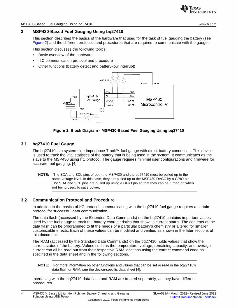
This section describes the basics of the hardware that used for the task of fuel gauging the battery (seeFigure 2) and the different protocols and procedures that are required to communicate with the gauge.
This section discusses the following topics:
• Basic overview of the hardware
• I2C communication protocol and procedure
• Other functions (battery detect and battery-low interrupt)
Figure 2. Block Diagram - MSP430-Based Fuel Gauging Using bq27410
3.1 bq27410 Fuel Gauge
The bq27410 is a system-side Impedance Track™ fuel gauge with direct battery connection. This deviceis used to track the vital statistics of the battery that is being used in the system. It communicates as theslave to the MSP430 using I2C protocol. The gauge requires minimal user configurations and firmware foraccurate fuel gauging. [4]
NOTE: The SDA and SCL pins of both the MSP430 and the bq27410 must be pulled up to thesame voltage level. In this case, they are pulled up to the MSP430 DVCC by a GPIO pin.The SDA and SCL pins are pulled up using a GPIO pin so that they can be turned off whennot being used, to save power.
3.2 Communication Protocol and Procedure
In addition to the basics of I2C protocol, communicating with the bq27410 fuel gauge requires a certainprotocol for successful data communication.
The data flash (accessed by the Extended Data Commands) on the bq27410 contains important valuesused by the fuel gauge to track the battery characteristics that show its current status. The contents of thedata flash can be programmed to fit the needs of a particular battery’s chemistry or altered for smallercustomizable effects. Each of these values can be modified and verified as shown in the later sections ofthis document.
The RAM (accessed by the Standard Data Commands) on the bq27410 holds values that show thecurrent status of the battery. Values such as the temperature, voltage, remaining capacity, and averagecurrent can all be read out from their respective RAM locations using the correct command code asspecified in the data sheet and in the following sections.
NOTE: For more information on other functions and values that can be set or read in the bq27410’sdata flash or RAM, see the device-specific data sheet [4].
Interfacing with the bq27410 data flash and RAM are treated separately, as they have differentprocedures.
4 MSP430™ Based Lithium-Ion Polymer Battery Charging and Gauging SLAA529A–March 2012–Revised June 2012Solution Using USB Power Submit Documentation Feedback
Copyright © 2012, Texas Instruments Incorporated

www.ti.com MSP430-Based Fuel Gauging Using bq27410
3.2.1 Writing and Reading bq27410 Data Flash
For a particular battery selected, the data flash values remain the same, and therefore, writing to andreading back from the data flash is done only at a production level and are customized to the battery’schemistry.
3.2.1.1 Writing to bq27410 Data Flash
Figure 3 shows the procedure to write the data flash on the bq27410.
Figure 3. bq27410 Fuel Gauge - Flash Data Write Flow Chart
What is most important to this procedure is ensuring that the correct checksum is being written. Withoutthe correct checksum written, the data flash block is not updated and retains the previously programmedvalues. To ensure that the update happens correctly, the firmware (bq27410_config.c andbq27410_config.h) reads the previous checksum, calculates the previous sum from this value, andupdates the sum byte-by-byte. By subtracting the previous read value (see Section 3.2.1.2) and addingthe new written value to the running sum of the data block, an accurate calculation value of the checksumis ensured.
Another key point to writing the data flash is the offset. The offset that is in the data sheet is a data byteoffset, not a block offset. As such, this offset value is assessed within the loop to write new data. For moreinformation, see the firmware associated with this application report.
5SLAA529A–March 2012–Revised June 2012 MSP430™ Based Lithium-Ion Polymer Battery Charging and GaugingSolution Using USB PowerSubmit Documentation Feedback
Copyright © 2012, Texas Instruments Incorporated

MSP430-Based Fuel Gauging Using bq27410 www.ti.com
3.2.1.2 Reading from Data Flash
Figure 4 shows the steps for reading the data flash.
Figure 4. bq27410 Fuel Gauge - Flash Data Read Flow Chart
3.2.2 Writing and Reading the bq27410 RAM
As mentioned before, writing to and reading from the RAM of the bq27410 is different from writing to andreading from the data flash. The method for reading and writing the device RAM is a much more directprocess.
To access the RAM values, only one byte of data has to be written. Following this, the corresponding datavalues can be directly read back with a read of the sufficient amount of data bytes.
The command bytes that are used to access the bq27410 RAM are referred to as the "Standard DataCommands" in the device data sheet [4]. These values can be read out individually or as an entire blockof data.
3.3 Battery Insertion and Removal Detection
As mentioned in the section regarding the battery charger (bq24230), a combination of commands andinteractions between devices is necessary to accurately detect a battery connection event and toefficiently handle such an event. To do this successfully, the application uses the CE functionality of thebq24230 in conjunction with polling the REG25 pin of the bq27410 to test if a battery is attached or not.
When the battery is removed, the REG25 pin of the bq27410 goes LOW, causing the falling edge eventand an interrupt on the related MSP430 GPIO pin. In the GPIO ISR, CE is set HIGH to disable chargingand conserve current and then the interrupt edge select for the GPIO pin is toggled.
When the battery is inserted, the REG25 pin of the bq27410 goes HIGH, causing the rising edge eventand an interrupt to be triggered. In the GPIO ISR, CE is set LOW to re-enable charging, and the interruptedge is toggled again. A flag is also then set by the ISR that allows the BAT_INSERT command to besent prior to the next access of the bq27410 RAM contents.
6 MSP430™ Based Lithium-Ion Polymer Battery Charging and Gauging SLAA529A–March 2012–Revised June 2012Solution Using USB Power Submit Documentation Feedback
Copyright © 2012, Texas Instruments Incorporated

www.ti.com MSP430 USB Operation
NOTE:• If USB power is not present in the system, a battery removal is treated as a loss of
power to the system. Upon reinserting the battery, a power on reset (POR) is triggeredfor the MSP430, thus resetting the device.
• The BAT_INSERT command should only be sent to the bq27410 when a battery insertevent is detected and not every time the RAM is accessed. While sending the commandfor RAM accesses does not cause any communication problems, it is done in bestpractice to reduce power consumption of the system.
• Removing the battery from the system when the USB is still connected is not fullysupported in this solution. If the battery is removed when the MSP430 is communicatingwith the fuel gauge through I2C, the communication hangs and the MSP430 requires areset or power cycle to resume operation. This configuration can be accounted for byadding an I2C time-out (planned for support in a future release).
3.4 Battery State of Charge Interrupt or Battery-Low Detect
The GPOUT pin of the bq27410 fuel gauge can be used for either of the two following functions: state ofcharge (SOC) interrupt or battery-low detect interrupt.
For this application, the state of charge interrupt function of the GPOUT pin was chosen over the battery-low detect function. This was chosen because the internal battery-low detect thresholds of the device weretoo high to be applicable to the 300-mAh Tenergy battery [1] used in the demo application.
The state of charge interrupt helps to chart the battery’s charge from a high-level perspective. That is, thecomplete battery charge range (0 to 100%) is divided into "x" sections (also referred to as "bars" in thisapplication report) with each section representing "100 / x"% charge. When the battery’s charge reaches alimit of one of these sections, an SOC interrupt is generated on the GPOUT pin. The GPOUT pin isconnected to an interrupt capable GPIO pin on the MSP430, which increments or decrements the "bars"counter based on if the battery is charging or discharging, respectively. Also, upon a battery insert event,this counter is refreshed using the most recent SOC reading from the bq27410 RAM to re-establish thebattery’s status.
4 MSP430 USB Operation
This section describes the basics of the different USB power configurations and connection states, as wellas how each USB state is handled in this particular application. It also describes the power consumptionvalues of individual devices in the system and the entire system in each of the different USB powerconfigurations.
4.1 USB Power Configuration Basics
When a USB device (meaning not just the MSP430, but the entire physical device) is connected to a USBhost, the host provides 5-V power over the USB cable; this power source is referred to as VBUS. Fordevices that are permanently "tethered" to the USB host (that is, devices that function only when attachedto the host), this "VBUS" may eliminate the need for a battery or other local source. Such a device is saidto be bus-powered. By strict definition, a bus-powered device derives all of its power from VBUS.
In applications where the USB device is not permanently tethered to the host (that is, the device has anoption to be disconnected and reconnected back to the host intermittently), the device might have its ownlocal power source (battery or some other external source). A device that derives some of its power from alocal source while connected to a USB host is called a self-powered device.
A USB device with its own local power source often powers itself completely from the local source whennot attached to the host but takes advantage of VBUS when attached. This is often necessary becausekeeping an active connection to a USB host drains considerable power, adding additional load on thedevice’s battery. However, because the USB connection requires very little power when the USB device issuspended by the host, the device may be designed to revert to local power during suspend.
7SLAA529A–March 2012–Revised June 2012 MSP430™ Based Lithium-Ion Polymer Battery Charging and GaugingSolution Using USB PowerSubmit Documentation Feedback
Copyright © 2012, Texas Instruments Incorporated
MSP430 USB Operation www.ti.com
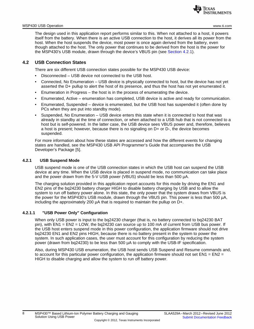
The design used in this application report performs similar to this. When not attached to a host, it powersitself from the battery. When there is an active USB connection to the host, it derives all its power from thehost. When the host suspends the device, most power is once again derived from the battery, eventhough attached to the host. The only power that continues to be derived from the host is the power forthe MSP430’s USB module, drawn through the device’s VBUS pin (see Section 4.2.1).
4.2 USB Connection States
There are six different USB connection states possible for the MSP430 USB device:
• Disconnected – USB device not connected to the USB host.
• Connected, No Enumeration – USB device is physically connected to host, but the device has not yetasserted the D+ pullup to alert the host of its presence, and thus the host has not yet enumerated it.
• Enumeration in Progress – the host is in the process of enumerating the device.
• Enumerated, Active – enumeration has completed, USB device is active and ready for communication.
• Enumerated, Suspended – device is enumerated, but the USB host has suspended it (often done byPCs when they are put into standby mode).
• Suspended, No Enumeration – USB device enters this state when it is connected to host that wasalready in standby at the time of connection, or when attached to a USB hub that is not connected to ahost but is self-powered. In the latter case, the USB device sees VBUS power and, therefore, believesa host is present; however, because there is no signaling on D+ or D-, the device becomessuspended.
For more information about how these states are accessed and how the different events for changingstates are handled, see the MSP430 USB API Programmer’s Guide that accompanies the USBDeveloper’s Package [5].
4.2.1 USB Suspend Mode
USB suspend mode is one of the USB connection states in which the USB host can suspend the USBdevice at any time. When the USB device is placed in suspend mode, no communication can take placeand the power drawn from the 5-V USB power (VBUS) should be less than 500 µA.
The charging solution provided in this application report accounts for this mode by driving the EN1 andEN2 pins of the bq24230 battery charger HIGH to disable battery charging by USB and to allow thesystem to run off battery power alone. In this state, the only power that the system draws from VBUS isthe power for the MSP430’s USB module, drawn through the VBUS pin. This power is less than 500 µA,including the approximately 200 µA that is required to maintain the pullup on D+.
4.2.1.1 "USB Power Only" Configuration
When only USB power is input to the bq24230 charger (that is, no battery connected to bq24230 BATpin), with EN1 = EN2 = LOW, the bq24230 can source up to 100 mA of current from USB bus power. Ifthe USB host enters suspend mode in this power configuration, the application firmware should not drivebq24230 EN1 and EN2 pins HIGH, because there is no battery present in the system to power thesystem. In such application cases, the user must account for this configuration by reducing the systempower (drawn from bq24230) to be less than 500 µA to comply with the USB-IF specification.
Also, during MSP430 USB enumeration, the USB host sends USB Suspend and Resume commands and,to account for this particular power configuration, the application firmware should not set EN1 = EN2 =HIGH to disable charging and allow the system to run off battery power.
8 MSP430™ Based Lithium-Ion Polymer Battery Charging and Gauging SLAA529A–March 2012–Revised June 2012Solution Using USB Power Submit Documentation Feedback
Copyright © 2012, Texas Instruments Incorporated

www.ti.com LiPo Battery Charging and Fuel Gauging Demo Application
5 LiPo Battery Charging and Fuel Gauging Demo Application
This section discusses the demo application as a whole. It combines all the information from the previoussections to give a full description of the final demo application.
5.1 Demo Application Hardware
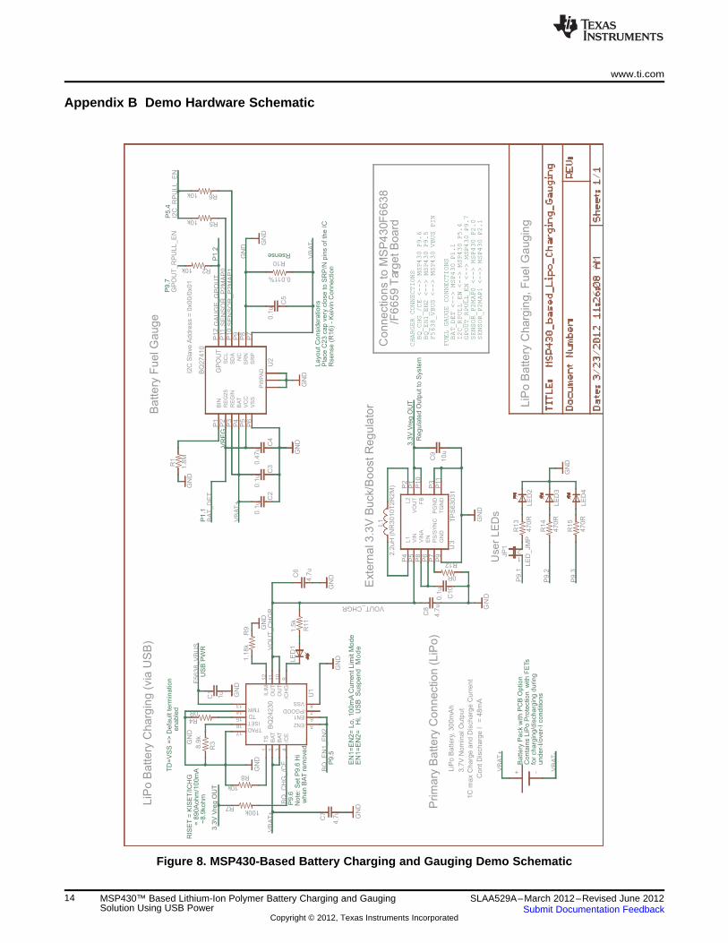
The LiPo battery charging and fuel gauging circuit should be connected to the MSP430F5638 orMSP430F6638 target board. See Appendix B for the related schematic.
5.2 Demo Application Operation
The basic operation of the demo application is shown in Table 3, Figure 5, and Figure 6. When theMSP430 is powered up, the device initializes all the pertinent peripherals and checks if a battery isconnected. If the battery is present, then RAM contents of the bq27410 fuel gauge are read and storedlocally. The device then checks the USB status. If the USB is connected and enumerated, the devicesends the fuel gauge information by USB Communications Device Class (CDC) to the PC.
NOTE: Using USB CDC protocol generates a virtual COM port on the PC and allows a UART-likeconnection between the PC and the device.
Table 3 describes the actions taken in each of the different USB connection states.
Table 3. USB Connection States and Operation
USB Connection State Actions Taken in Demo Application
Assert the D+ pullup (alert host of presence), go to sleep for 5 seconds, check if battery isConnected, No Enumeration connected
Send fuel gauge RAM data through USB CDC in background, go to sleep for 5 seconds, check ifEnumerated, Active battery is connected
Enumerated, Suspend Put charger in standby mode, sleep for 10 seconds, check if battery is connected
Enumeration in Progress Do not go to sleep, check if battery is connected
Suspend, No Enumeration Sleep for 10 seconds, check if battery is connected
Disconnected Sleep for 5 seconds, check if battery is connected
In each of these cases, if there is a battery connected, the RAM contents of the bq27410 fuel gauge andthen the USB state are evaluated.
For more detailed regarding the demo firmware and the associated code files, see Appendix A.
9SLAA529A–March 2012–Revised June 2012 MSP430™ Based Lithium-Ion Polymer Battery Charging and GaugingSolution Using USB PowerSubmit Documentation Feedback
Copyright © 2012, Texas Instruments Incorporated

LiPo Battery Charging and Fuel Gauging Demo Application www.ti.com
5.3 Application Flowcharts
Figure 5 shows a high-level flow chart of the demo application.
NOTE: See Table 3 for the "Appropriate USB Actions" for each of the different USB configurations.
Figure 5. MSP430-Based Battery Charging and Gauging Demo - High-level Flow Chart
10 MSP430™ Based Lithium-Ion Polymer Battery Charging and Gauging SLAA529A–March 2012–Revised June 2012Solution Using USB Power Submit Documentation Feedback
Copyright © 2012, Texas Instruments Incorporated

www.ti.com LiPo Battery Charging and Fuel Gauging Demo Application
Figure 6 is a more detailed flowchart of the demo application, delving into the finer details of the demofirmware.
NOTE: When using the demo example, ensure that a battery is attached before power up to ensure that thesystem is initialized properly.
Figure 6. MSP430-Based Battery Charging and Gauging Demo - Detailed Flow Chart
5.4 Demo Application Output
Figure 7 is a screenshot of the PC software (HyperTerminal) while the demo application is running. Whena battery is present in the system, the HyperTerminal window displays the bq27410 RAM values every fiveseconds. When a battery is removed from the system, the phrase "No Battery Connected" is displayed.
11SLAA529A–March 2012–Revised June 2012 MSP430™ Based Lithium-Ion Polymer Battery Charging and GaugingSolution Using USB PowerSubmit Documentation Feedback
Copyright © 2012, Texas Instruments Incorporated

References www.ti.com
Figure 7. MSP430-Based Battery Charging and Gauging Demo - HyperTerminal Screenshot
5.5 Power Consumption
Table 4 shows the current consumption for the system as a whole while using USB power.
Table 4. Power Consumption
Parameter Battery Charging Mode Battery Fully Charged or USB Suspend OR Batterybq24230 Termination Mode Discharging Mode
Current on VBUS 36.5 mA 12 mA 405 µA
Current at Charger 96.9 mA 48 µA 46.4 µ A
Current at Buck-Boost 30 µA 30 µA 30 µ A
VOUT Charger 4.4 V 4.4 V V BAT
VOUT Buck-Boost 3.3 V 3.3 V 3.3 V
NOTE: When in Battery Charging Mode, the bq24230 is in USB100 mode. Up to 100-mA chargingcurrent may be drawn when charging.
6 References
[1] Tenergy 3.7V 300mAh Lithium-Ion Polymer Battery (http://www.tenergy.com/Tenergy-Lithium-Ion-Polymer-3-7V-300mAh-561540-Rechargeable-Battery)
[2] bq24230 Battery Charger (SLUS821)
[3] TPS63030 3.3-V Buck-Boost Converter (SLVS696)
[4] bq27410 Fuel Gauge (SLUSAF4)
[5] MSP430 USB Developers Package (http://www.ti.com/tool/msp430usbdevpack)
12 MSP430™ Based Lithium-Ion Polymer Battery Charging and Gauging SLAA529A–March 2012–Revised June 2012Solution Using USB Power Submit Documentation Feedback
Copyright © 2012, Texas Instruments Incorporated
www.ti.com
Appendix A Associated Code Files
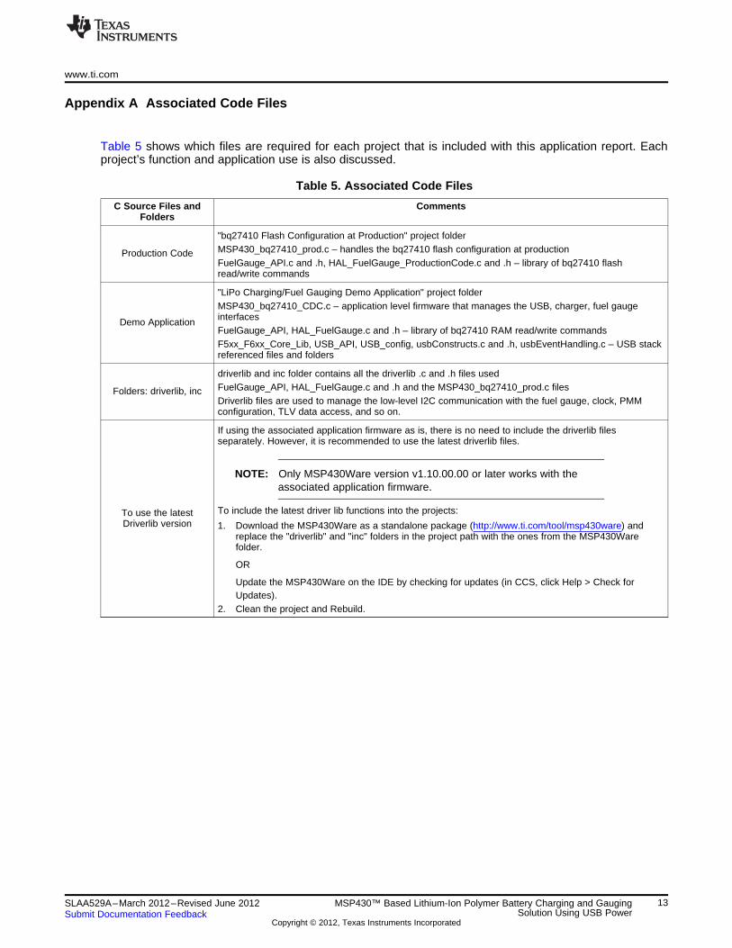
Table 5 shows which files are required for each project that is included with this application report. Eachproject’s function and application use is also discussed.
Table 5. Associated Code Files
C Source Files and CommentsFolders
"bq27410 Flash Configuration at Production" project folderMSP430_bq27410_prod.c – handles the bq27410 flash configuration at productionProduction CodeFuelGauge_API.c and .h, HAL_FuelGauge_ProductionCode.c and .h – library of bq27410 flashread/write commands
"LiPo Charging/Fuel Gauging Demo Application" project folderMSP430_bq27410_CDC.c – application level firmware that manages the USB, charger, fuel gaugeinterfacesDemo ApplicationFuelGauge_API, HAL_FuelGauge.c and .h – library of bq27410 RAM read/write commandsF5xx_F6xx_Core_Lib, USB_API, USB_config, usbConstructs.c and .h, usbEventHandling.c – USB stackreferenced files and folders
driverlib and inc folder contains all the driverlib .c and .h files usedFuelGauge_API, HAL_FuelGauge.c and .h and the MSP430_bq27410_prod.c filesFolders: driverlib, incDriverlib files are used to manage the low-level I2C communication with the fuel gauge, clock, PMMconfiguration, TLV data access, and so on.
If using the associated application firmware as is, there is no need to include the driverlib filesseparately. However, it is recommended to use the latest driverlib files.
NOTE: Only MSP430Ware version v1.10.00.00 or later works with theassociated application firmware.
To include the latest driver lib functions into the projects:To use the latestDriverlib version 1. Download the MSP430Ware as a standalone package (http://www.ti.com/tool/msp430ware) and
replace the "driverlib" and "inc" folders in the project path with the ones from the MSP430Warefolder.
OR
Update the MSP430Ware on the IDE by checking for updates (in CCS, click Help > Check forUpdates).
2. Clean the project and Rebuild.
13SLAA529A–March 2012–Revised June 2012 MSP430™ Based Lithium-Ion Polymer Battery Charging and GaugingSolution Using USB PowerSubmit Documentation Feedback
Copyright © 2012, Texas Instruments Incorporated
I2C
Sla
ve
Ad
dre
ss
= 0
x0
0/0
x0
1
+ -
2.2
uH
(N
R3
01
0T
2R
2M
)
GN
D
1.5
k
GN
D
GN
DG
ND
8.9
k
1.1
8k
GN
D
GN
D0R
GN
D
GN
D
GN
D
GN
D
10k
GN
D
GN
D1
.8M 10
u
4.7
u
4.7
u
1u
0.4
7u
0.1
u0
.1u
0.1
u
0.1
u4
.7u
100k
10k
10k
47
0R
47
0R
47
0R
LE
D_
JM
P
GN
D
LiP
oB
atte
ry C
harg
ing, F
uelG
augin
g
Exte
rnal3.3
VB
uck/B
oost R
egula
tor
Prim
ary
Batte
ry C
onnectio
n(L
iPo)
LiP
oB
atte
ry C
harg
ing
(via
US
B)
Batte
ry F
uelG
auge
1C
ma
x C
ha
rge
an
d D
isch
arg
e C
urr
en
t
3.7
V N
om
ina
l O
utp
ut
Co
nt
Dis
ch
arg
e I
= 4
8m
A
LiP
o B
att
ery
, 3
00
mA
h
Connections to M
SP
430F
6638
/F6
659
Tar
get B
oard
User
LE
Ds
LE
D1
R11
R3
R9
L1
1 2 3 4
6
7
8
910
11
12
14
15
16
TS
BA
T
BA
T
/CE
EN1/PGOOD
VSS
/CH
G
OU
T
OU
T
ILIM
TMR
TD
ISET
U1
BQ
24
23
0
TPAD
R4B
INP
1
RE
G2
5P
2
RE
GIN
P3
BA
TP
4
VC
CP
5
VS
SP
6S
RP
P7
SR
NP
8N
CP
9S
DA
P1
0S
CL
P11
GP
OU
TP
12
U2
BQ
27
41
0
PW
PA
D
R2
R1 C
9
C7
C6
C1
C4
C2
C3
C5
C1
0
C8
R7
VO
UT
P1
L2
P2
PG
ND
P3
L1
P4
VIN
P5
EN
P6
PS
/SY
NC
P7
VIN
AP
8
GN
DP
9
FB
P1
0
TP
S6
30
31
TG
ND
P11
U3
R6
LE
D4
R1
5
LE
D2
R1
3
LE
D3
R1
4
2
JP
1
GN
D
GN
D
VB
AT
+
VB
AT
+
VB
AT
+
VO
UT
_C
HG
R
VB
AT-
VB
AT-
GA
UG
E_
GP
OU
T
BQ
_E
N1
_E
N2
BA
T_
DE
T
SE
NS
OR
_P
2M
AP
0S
EN
SO
R_
P2
MA
P1
F5
63
8_
VB
US
GP
OU
T_
RP
UL
L_
EN
BQ
_C
HG
_/C
E
I2C
_R
PU
LL
_E
N
P9
.3
P9
.2
P9
.1
EN
1=
EN
2=
Lo
, 1
00
mA
Cu
rre
nt
Lim
it M
od
e
RIS
ET
= K
ISE
T/I
CH
G=
89
0A
oh
m/1
00
mA
~8
.9koh
m
Ba
tte
ry P
ack
with
PC
B O
ptio
nC
on
tain
s L
iPo
Pro
tectio
n
with
FE
Ts
for
cha
rgin
g/d
ischa
rgin
g d
urin
gu
nd
er-
I/o
ve
r-I
con
ditio
ns
3.3
V V
reg
OU
T
EN
1=
EN
2=
Hi,
US
BS
usp
en
dM
od
e
Rsense
P1
.1
P1
.2
Pla
ce
C2
3 c
ap
ve
ry c
lose
to
SR
P/N
pin
s o
f th
e I
CR
se
nse
(R1
6)
- K
elv
in C
on
ne
ctio
nP
9.5
VR
EG
La
yo
ut
Co
nsid
era
tio
ns
TD
=V
SS
=>
De
fau
lt t
erm
ina
tio
ne
na
ble
d
P9
.7
P9
.6N
ote
: S
et
P9
.6 H
iw
he
n B
AT
rem
ove
d
3.3
V V
reg
OU
T
P5
.4
US
B P
WR
BQ_CHG_/CE<--> MSP430P9.6
BQ_EN1_EN2 <--> MSP430P9.5
BAT_DET<--> MSP430P1.1
CHARGER CONNECTIONS
I2C_RPULL_EN<--> MSP430P5.4
GPOUT_RPULL_EN<--> MSP430P9.7
SENSOR_P2MAP0 <--> MSP430P2.0
SENSOR_P2MAP1 <--> MSP430P2.1
FUEL GAUGE CONNECTIONS
F5638_VBUS<--> MSP430VBUS PIN
Re
gu
late
d O
utp
ut
to S
yste
m
10k
R8
17
13
5EN2
VOUT_CHGR
R12
0R
1
R5
R10
0.011%
www.ti.com
Appendix B Demo Hardware Schematic
Figure 8. MSP430-Based Battery Charging and Gauging Demo Schematic
14 MSP430™ Based Lithium-Ion Polymer Battery Charging and Gauging SLAA529A–March 2012–Revised June 2012Solution Using USB Power Submit Documentation Feedback
Copyright © 2012, Texas Instruments Incorporated
IMPORTANT NOTICE
Texas Instruments Incorporated and its subsidiaries (TI) reserve the right to make corrections, modifications, enhancements, improvements,and other changes to its products and services at any time and to discontinue any product or service without notice. Customers shouldobtain the latest relevant information before placing orders and should verify that such information is current and complete. All products aresold subject to TI’s terms and conditions of sale supplied at the time of order acknowledgment.
TI warrants performance of its hardware products to the specifications applicable at the time of sale in accordance with TI’s standardwarranty. Testing and other quality control techniques are used to the extent TI deems necessary to support this warranty. Except wheremandated by government requirements, testing of all parameters of each product is not necessarily performed.
TI assumes no liability for applications assistance or customer product design. Customers are responsible for their products andapplications using TI components. To minimize the risks associated with customer products and applications, customers should provideadequate design and operating safeguards.
TI does not warrant or represent that any license, either express or implied, is granted under any TI patent right, copyright, mask work right,or other TI intellectual property right relating to any combination, machine, or process in which TI products or services are used. Informationpublished by TI regarding third-party products or services does not constitute a license from TI to use such products or services or awarranty or endorsement thereof. Use of such information may require a license from a third party under the patents or other intellectualproperty of the third party, or a license from TI under the patents or other intellectual property of TI.
Reproduction of TI information in TI data books or data sheets is permissible only if reproduction is without alteration and is accompaniedby all associated warranties, conditions, limitations, and notices. Reproduction of this information with alteration is an unfair and deceptivebusiness practice. TI is not responsible or liable for such altered documentation. Information of third parties may be subject to additionalrestrictions.
Resale of TI products or services with statements different from or beyond the parameters stated by TI for that product or service voids allexpress and any implied warranties for the associated TI product or service and is an unfair and deceptive business practice. TI is notresponsible or liable for any such statements.
TI products are not authorized for use in safety-critical applications (such as life support) where a failure of the TI product would reasonablybe expected to cause severe personal injury or death, unless officers of the parties have executed an agreement specifically governingsuch use. Buyers represent that they have all necessary expertise in the safety and regulatory ramifications of their applications, andacknowledge and agree that they are solely responsible for all legal, regulatory and safety-related requirements concerning their productsand any use of TI products in such safety-critical applications, notwithstanding any applications-related information or support that may beprovided by TI. Further, Buyers must fully indemnify TI and its representatives against any damages arising out of the use of TI products insuch safety-critical applications.
TI products are neither designed nor intended for use in military/aerospace applications or environments unless the TI products arespecifically designated by TI as military-grade or "enhanced plastic." Only products designated by TI as military-grade meet militaryspecifications. Buyers acknowledge and agree that any such use of TI products which TI has not designated as military-grade is solely atthe Buyer's risk, and that they are solely responsible for compliance with all legal and regulatory requirements in connection with such use.
TI products are neither designed nor intended for use in automotive applications or environments unless the specific TI products aredesignated by TI as compliant with ISO/TS 16949 requirements. Buyers acknowledge and agree that, if they use any non-designatedproducts in automotive applications, TI will not be responsible for any failure to meet such requirements.
Following are URLs where you can obtain information on other Texas Instruments products and application solutions:
Products Applications
Audio www.ti.com/audio Automotive and Transportation www.ti.com/automotive
Amplifiers amplifier.ti.com Communications and Telecom www.ti.com/communications
Data Converters dataconverter.ti.com Computers and Peripherals www.ti.com/computers
DLP® Products www.dlp.com Consumer Electronics www.ti.com/consumer-apps
DSP dsp.ti.com Energy and Lighting www.ti.com/energy
Clocks and Timers www.ti.com/clocks Industrial www.ti.com/industrial
Interface interface.ti.com Medical www.ti.com/medical
Logic logic.ti.com Security www.ti.com/security
Power Mgmt power.ti.com Space, Avionics and Defense www.ti.com/space-avionics-defense
Microcontrollers microcontroller.ti.com Video and Imaging www.ti.com/video
RFID www.ti-rfid.com
OMAP Mobile Processors www.ti.com/omap
Wireless Connectivity www.ti.com/wirelessconnectivity
TI E2E Community Home Page e2e.ti.com
Mailing Address: Texas Instruments, Post Office Box 655303, Dallas, Texas 75265Copyright © 2012, Texas Instruments Incorporated