Embed Size (px)
Citation preview

MODY MSP4 SERIES
SUBMERSIBLEPUMPS:
DRY PITWET PIT
PORTABLE
MOTORS:4-POLE 37 - 70 kW6-POLE 13 - 37 kW8-POLE 7.5 - 15 kW
380V-400V-415V/3PH/50HZ
FLOWS to 930 M3/H
HEADS to 60 METRES
VORTEX OR CHANNELIMPELLERS
FEATURES
HIGH EFFICIENCY MOTORS WITH CLASS H (180°C)INSULATION SYSTEM
EXTENDED SERVICE LIFE CYCLE EXCELLENT FOR VFD APPLICATIONS
INTEGRAL ”ECO-FRIENDLY” COOLING SYSTEM SELF-CONTAINED - NO EXTERNAL COOLING
WATER SYSTEM REQUIRED ELIMINATES FOULING FROM PUMPAGE COOLED
DESIGNS EXCELLENT FOR CONTINUOUS RUN, DRY PIT
APPLICATIONS ”FAST - CHANGE” CARTRIDGE MECHANICAL SEALS
WITH SILICON CARBIDE SEAL FACES EXTENDED SERVICE LIFE CYCLE EASY MAINTENANCE IN FIELD NO SPECIAL TOOL REQUIREMENTS
ADJUSTABLE WEAR RING SYSTEM EXTENDED SERVICE LIFE CYCLE EASY MAINTENANCE OF RUNNING CLEARANCES
IN THE FIELD PREVENTS ”RAGGING” NO SPECIAL TOOL REQUIREMENTS
VORTEX OR ENCLOSED IMPELLER IN SAME VOLUTE ON SAME MOTOR SHAFT EASY EXCHANGE IN THE FIELD NO SPECIAL TOOL REQUIREMENTS
”FAST - LOCK”, QUICK-RELEASE, LATCH-BOLTS EASY MAINTENANCE IN THE FIELD ELIMINATES NEED FOR VOLUTE HAND HOLE
OIL TAP DRAIN INTERCHANGEABLE PARTS WITH PUMPEX® BRAND
MODELS EASY RETROFIT TO FLYGT® AND MOST OTHER
BRAND INSTALLATIONS
Mody Pumps® Inc.2166 Zeus Court • Bakersfield, CA 93308 USAPhone +1 (661) 392.7600 • Fax +1 (661) 392.7601http://www.modypump.com • [email protected]
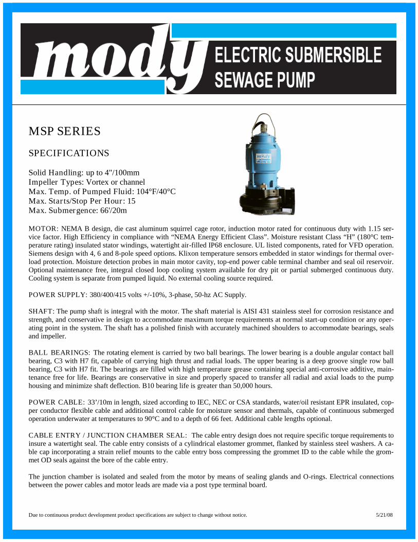
MSP SERIES
SPECIFICATIONS
Solid Handling: up to 4"/100mmImpeller Types: Vortex or channelMax. Temp. of Pumped Fluid: 104°F/40°CMax. Starts/Stop Per Hour: 15Max. Submergence: 66'/20m
MOTOR: NEMA B design, die cast aluminum squirrel cage rotor, induction motor rated for continuous duty with 1.15 ser-vice factor. High Efficiency in compliance with “NEMA Energy Efficient Class”. Moisture resistant Class “H” (180°C tem-perature rating) insulated stator windings, watertight air-filled IP68 enclosure. UL listed components, rated for VFD operation.Siemens design with 4, 6 and 8-pole speed options. Klixon temperature sensors embedded in stator windings for thermal over-load protection. Moisture detection probes in main motor cavity, top-end power cable terminal chamber and seal oil reservoir.Optional maintenance free, integral closed loop cooling system available for dry pit or partial submerged continuous duty.Cooling system is separate from pumped liquid. No external cooling source required.
POWER SUPPLY: 380/400/415 volts +/-10%, 3-phase, 50-hz AC Supply.
SHAFT: The pump shaft is integral with the motor. The shaft material is AISI 431 stainless steel for corrosion resistance andstrength, and conservative in design to accommodate maximum torque requirements at normal start-up condition or any oper-ating point in the system. The shaft has a polished finish with accurately machined shoulders to accommodate bearings, sealsand impeller.
BALL BEARINGS: The rotating element is carried by two ball bearings. The lower bearing is a double angular contact ballbearing, C3 with H7 fit, capable of carrying high thrust and radial loads. The upper bearing is a deep groove single row ballbearing, C3 with H7 fit. The bearings are filled with high temperature grease containing special anti-corrosive additive, main-tenance free for life. Bearings are conservative in size and properly spaced to transfer all radial and axial loads to the pumphousing and minimize shaft deflection. B10 bearing life is greater than 50,000 hours.
POWER CABLE: 33’/10m in length, sized according to IEC, NEC or CSA standards, water/oil resistant EPR insulated, cop-per conductor flexible cable and additional control cable for moisture sensor and thermals, capable of continuous submergedoperation underwater at temperatures to 90°C and to a depth of 66 feet. Additional cable lengths optional.
CABLE ENTRY / JUNCTION CHAMBER SEAL: The cable entry design does not require specific torque requirements toinsure a watertight seal. The cable entry consists of a cylindrical elastomer grommet, flanked by stainless steel washers. A ca-ble cap incorporating a strain relief mounts to the cable entry boss compressing the grommet ID to the cable while the grom-met OD seals against the bore of the cable entry.
The junction chamber is isolated and sealed from the motor by means of sealing glands and O-rings. Electrical connectionsbetween the power cables and motor leads are made via a post type terminal board.
Due to continuous product development product specifications are subject to change without notice. 5/21/08

SHAFT SEALS: Cartridge double mechanical shaft seal system to facilitate easy seal changes in the field without specialtools. Seal faces are silicon carbide against silicon carbide for long life and resistance to heat and abrasion. Seals operate main-tenance free in a reservoir of food grade oil that hydro-dynamically lubricates the seal faces at a constant rate, providing supe-rior heat transfer and maximum cooling. The reservoir is designed to prevent overfilling and to provide lubricant expansioncapacity. The oil tap drain has a positive anti-leak seal and is easily accessible from the outside of the pump. The seal systemdoes not rely upon the pumped media for lubrication and will not be damaged when the pump is run dry.
SEAL FAILURE EARLY WARNING SYSTEM: A moisture detection probe is provided in the seal oil chamber for detect-ing the presence of moisture. A relay device (by others) mounted in the pump control panel or in a separate enclosure sends alow voltage, low amperage signal to the probe. If moisture is present (determined by decreased resistance signals), the relaydevice energizes a warning light or shutdown circuit in the control panel, protecting the motor from damage.
IMPELLER: Enclosed or vortex, specifically designed for non-clog operation, dynamically balanced and trimmed to meetspecified hydraulic operating conditions. The impeller is designed with integral back vanes to prevent solids build-up in themechanical seal area and to control axial thrust loads on bearings during operation. The impeller slip fits onto the motor shaftwith a drive key and is fastened to the shaft by a stainless steel lock screw which is mechanically prevented from loosening bya ratcheting washer assembly that is positively engaged. Channel and vortex impellers are interchangeable with one another inthe field without modification to the pump or the need for special tools.
ADJUSTABLE WEAR RING SYSTEM: A replaceable wear ring is securely fitted the pump casing by no less than 3stainless steel set screws. The wear ring is capable of axial adjustment to reduce hydraulic losses between itself and the en-closed type impeller when wear affects pump efficiency and “Ragging”. This adjustment does not require special tools.
FAST LOCK LATCH BOLTS: The pump includes fast lock / quick release mechanisms with 304 stainless steel latch boltsto allow easy removal of the motor unit from the pump volute without disturbing system piping and the need for special tools.With this feature, a volute hand-hole cover for cleanout access is not required.
LIFTING HANDLE: The pump is supplied with a high quality, high strength stainless steel lifting handle. The handle has awide opening for easy pump handling and simplified retrieval from any installation.
PUMP VOLUTE: The pump volute is a centerline discharge design, with optional inlet and discharge sizes as specified bytechnical documentation. Passages are smooth and sized to pass large diameter solids.
MATERIALS OF CONSTRUCTIONDescription MaterialStator Casing: Cast iron ASTM A-48, Class 35Pump Volute/Casing: Cast iron ASTM A-48, Class 35Casing Wear Ring: Cast iron ASTM A-48, Class 35Lifting Handle: AISI 316 stainless steelImpeller: Ductile iron ASTM A-395, Grade 60-40-18Shaft: AISI 431 stainless steelShaft Sleeve: AISI 431 stainless steelHardware: AISI 304 stainless steelMechanical Seal: Fast change cartridge, double with silicon carbide vs. silicon carbide facesO-Rings: Nitrile rubber
SURFACE TREATMENT: Primer with Epoxy and subsequently coated with black air dry enamel.
Due to continuous product development product specifications are subject to change without notice. 5/21/08

LIMITED WARRANTY
We warrant to our immediate customer and to the ultimate consumer that products of our manufacture will be free of defects in mate-rial and workmanship under normal use and service for the following time periods, when installed and maintained in accordancewith our instructions.PUMPS: One (1) year from date of installation or (18) months from date of shipment, whichever occurs first. As used herein, “theultimate consumer” is defined as the purchaser who first uses the product after it’s initial installation or, in the case for product de-signed for non-permanent installation, the first owner who uses the product. It is the purchaser’s or any sub-vendor’s obligation tomake known to the ultimate consumer the terms and conditions of this warranty. This warranty gives you specific legal rights, andthere may also be other rights which vary from state to state. In the event the product is covered by the Federal Consumer ProductWarranties Law (1) the duration of any implied warranties associated with the product by virtue of said law is limited to the sameduration as stated herein, (2) this warranty is a LIMITED WARRANTY, and (3) no claims of any nature whatsoever shall be madeagainst us, until the ultimate consumer, his successor, or assigns, notifies us in writing of the defect, and delivers the product and/ordefective part(s) freight prepaid to our facility or nearest authorized service station. Some states do not allow limitations on how longan implied warranty lasts, so the above limitation may not apply. THE SOLE AND EXCLUSIVE REMEDY FOR BREACH OFANY AND ALL WARRANTIES WITH RESPECT TO ANY PRODUCT SHALL BE TO REPLACE OR REPAIR AT OURELECTION, FOB POINT OF MANUFACTURE OR AUTHORIZED REPAIR STATION, SUCH PRODUCTS AND/ORPARTS AS PROVEN DEFECTIVE. THERE SHALL BE NO FURTHER LIABILITY, WHETHER BASED ON WAR-RANTY, NEGLIGENCE OR OTHERWISE.Unless expressly stated otherwise, guarantees in the nature of performance specifications furnished in addition to the foregoing mate-rial and workmanship warranties on a product manufactured by Mody, if any, are subject to laboratory tests corrected for field per-formance. Any additional guarantees, in the nature of performance specifications must be in writing and such writing must be signedby our authorized representative. Due to inaccuracies in field testing if a conflict arises between the results of field testing conductedby or for user, and laboratory tests corrected for field performance, the latter shall control. Components or accessories supplied by usbut manufactured by others are warranted only to the extent of and by the terms and conditions of the original manufacturer’s war-ranty.RECOMMENDATIONS FOR SPECIAL APPLICATIONS OR THOSE RESULTING FROM SYSTEMS ANALYSES ANDEVALUATIONS WE CONDUCT, WILL BE BASED ON OUR BEST AVAILABLE EXPERIENCE AND PUBLISHEDINDUSTRY INFORMATION. SUCH RECOMMENDATIONS DO NOT CONSTITUTE A WARRANTY OF SATISFAC-TORY PERFORMANCE AND NO SUCH WARRANTY IS GIVEN.This warranty shall not apply when damage is caused by (a) improper installation, (b) improper voltage, (c) lightning, (d) sand orother abrasive materials, (e) scale or corrosion build-up due to excessive chemical content. Any modification of the equipment willalso void the warranty. We will not be responsible for loss, damage or labor cost due to interruption of service caused by defectiveparts. Neither will we accept charges incurred by others without our prior written approval. This warranty is void if our inspectionreveals the product was used in a manner inconsistent with normal industry practice and/or our specific recommendations. The pur-chaser is responsible for communication of all necessary information regarding the application and use of the product. UNDER NOCIRCUMSTANCES WILL WE BE RESPONSIBLE FOR ANY OTHER DIRECT OR CONSEQUENTIAL DAMAGES,INCLUDING BUT NOT LIMITED TO LOST PROFITS, LOST INCOME, LABOR CHARGES, DELAYS IN PRODUC-TION, IDLE PRODUCTION, WHICH DAMAGES ARE CAUSED BY ANY DEFECTS IN MATERIAL, AND/OR WORK-MANSHIP AND/OR DELAYS IN SHIPMENT. THIS WARRANTY IS EXPRESSLY IN LIEU OF ANY OTHER EXPRESSOR IMPLIED WARRANTY, INCLUDING ANY WARRANTY OF MERCHANTABILITY OR FITNESS FOR A PAR-TICULAR PURPOSE. No rights extended under this warranty shall be assigned to any person, whether by operation or otherwise,without our prior written approval.
MODY PUMPS, INC2166 Zeus Court, Bakersfield, CA 93308 USA
Phone: +1 (661) 392.7600 ▪ Fax: +1 (661) 392.7601

MSP4-150.0-4 Channel 11460 RPM
Head
Shaft pow er P2
Eff iciency
NPSH-values
Ø 350
80.9%
Ø 320
79.5%
Ø 290
71.6%Ø 370
81.2%Eff.
Ø 290 (P2)
Ø 370 (P2)
Ø 290
Ø 370
Ø 290Ø 370
4
8
12
16
20
24
28
32
36
40
44
48
52
56
[m]
10
20
30
40
[kW]
010203040506070
[%]
0
2
4
6
8
[m]
0 40 80 120 160 200 240 280 320 360 400 440 480 520 560 [m³/h]

MSP4-150.0-4 Channel 21460 RPM
Head
Shaft pow er P2
Efficiency
NPSH-values
Ø 325
62.7%
Ø 370
70.9%Eff.
Ø 325 (P2)
Ø 370 (P2)
Ø 325
Ø 370
Ø 325Ø 370
4
8
12
16
20
24
28
32
36
40
44
48
52
[m]
10
15
20
25
30
[kW]
0
10
20
30
40
50
60
[%]
0
2
4
6
8
[m]
0 40 80 120 160 200 240 280 320 360 400 440 480 520 560 [m³/h]

MSP4-150.0-4 Vortex 11460 RPM
Head
Shaft pow er P2
Eff iciency
NPSH-values
Ø 350
57.4%
Ø 310
56.7%
Ø 370
57.7%Eff.
Ø 310 (P2)
Ø 370 (P2)
Ø 310
Ø 370
Ø 310
Ø 370
4
8
12
16
20
24
28
32
36
40
44
48
52
[m]
1520253035404550
[kW]
0
10
20
30
40
50
[%]
4
6
8
10
[m]
0 40 80 120 160 200 240 280 320 360 400 440 480 520 560 [m³/h]
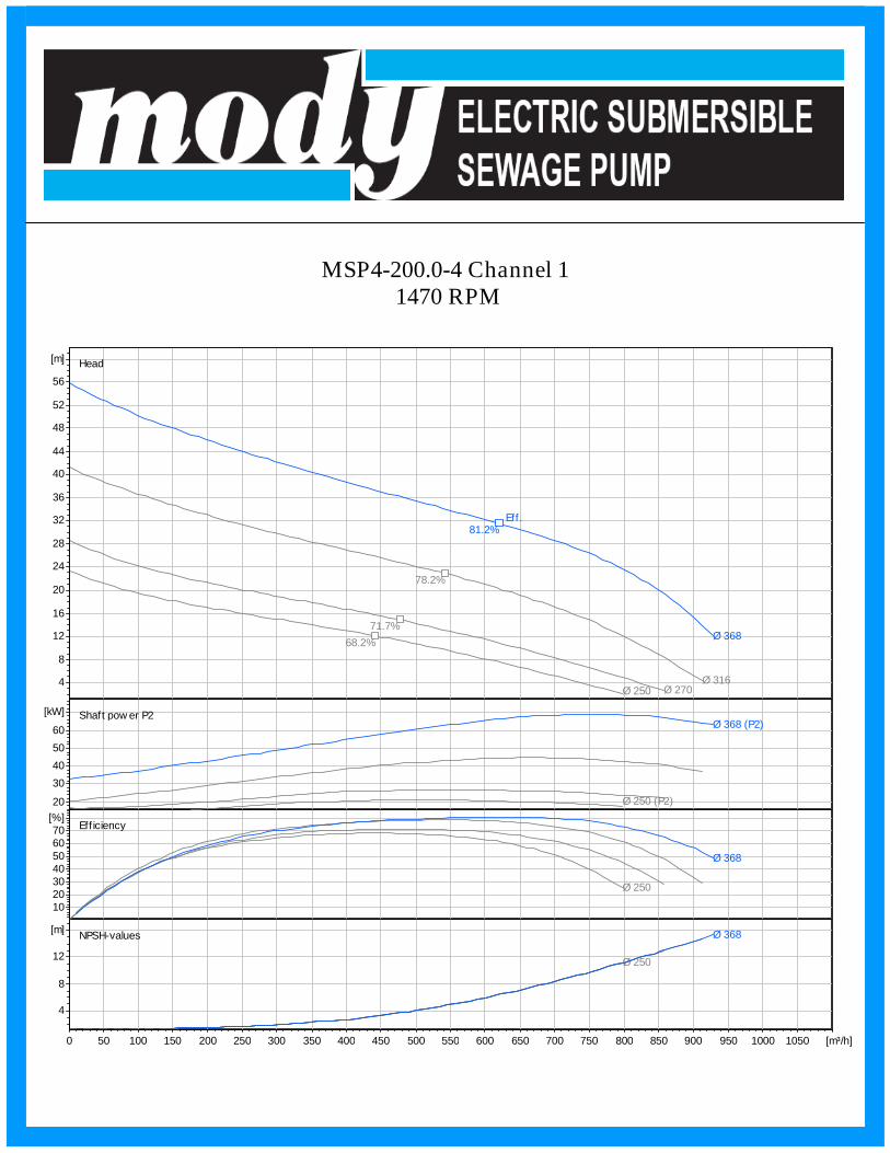
MSP4-200.0-4 Channel 11470 RPM
Head
Shaft pow er P2
Eff iciency
NPSH-values
Ø 316
78.2%
Ø 270
71.7%
Ø 250
68.2%Ø 368
81.2%Eff.
Ø 250 (P2)
Ø 368 (P2)
Ø 250
Ø 368
Ø 250
Ø 368
4
8
12
16
20
24
28
32
36
40
44
48
52
56
[m]
20
30
40
50
60
[kW]
10203040506070
[%]
4
8
12
[m]
0 50 100 150 200 250 300 350 400 450 500 550 600 650 700 750 800 850 900 950 1000 1050 [m³/h]

MSP4-200.0-6 Channel 1970 RPM
Head
Shaft pow er P2
Eff iciency
NPSH-values
Ø 328
76.7%
Ø 288
72.8%
Ø 368
80.6%Eff.
Ø 288 (P2)
Ø 368 (P2)
Ø 288Ø 368
Ø 288
Ø 368
0123456789
1011121314151617181920212223242526[m]
4
8
12
16
[kW]
10203040506070
[%]
2
34
567
8[m]
0 40 80 120 160 200 240 280 320 360 400 440 480 520 560 600 640 680 720 760 800 840 [m³/h]
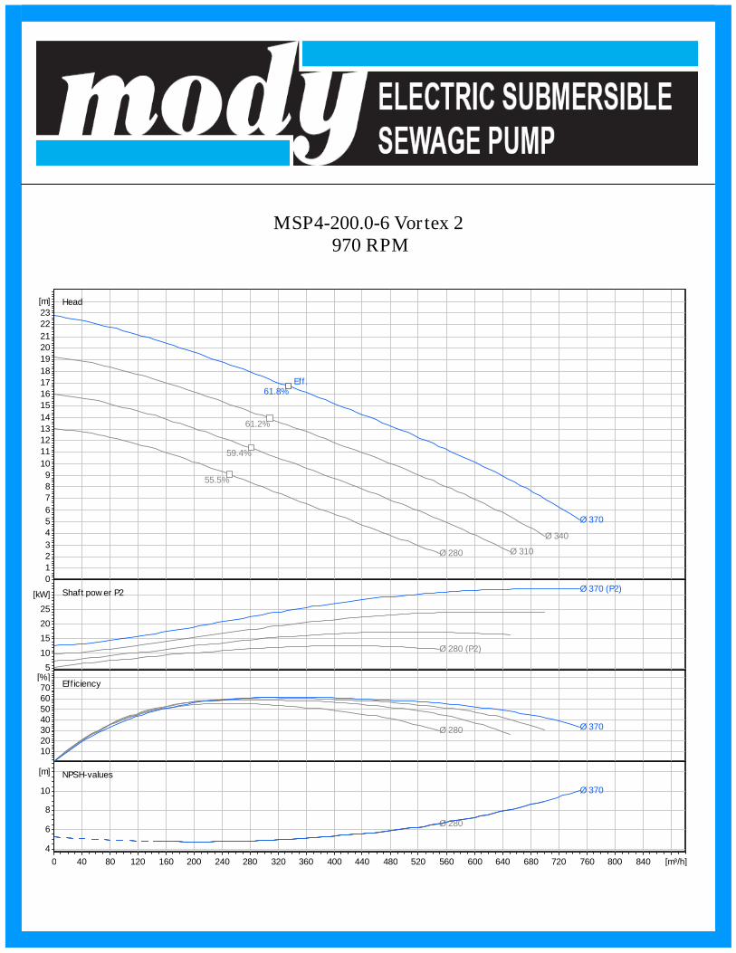
MSP4-200.0-6 Vortex 2970 RPM
Head
Shaft pow er P2
Eff iciency
NPSH-values
Ø 340
61.2%
Ø 310
59.4%
Ø 280
55.5%
Ø 370
61.8%Eff.
Ø 280 (P2)
Ø 370 (P2)
Ø 280 Ø 370
Ø 280
Ø 370
0
1
2
3
4
5
6
7
8
9
10
11
12
13
14
15
16
17
18
19
20
21
22
23
[m]
5
10
15
20
25
[kW]
10203040506070
[%]
4
6
8
10
[m]
0 40 80 120 160 200 240 280 320 360 400 440 480 520 560 600 640 680 720 760 800 840 [m³/h]

MSP4-SERIESWET PIT INSTALLATION
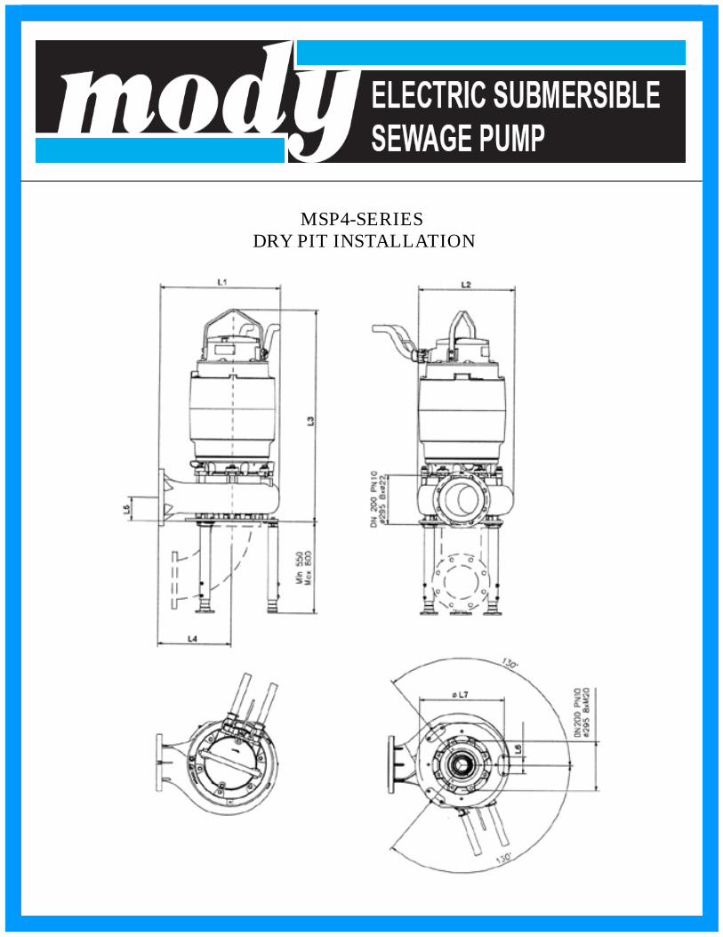
MSP4-SERIESDRY PIT INSTALLATION

MSP4-SERIESPORTABLE INSTALLATION
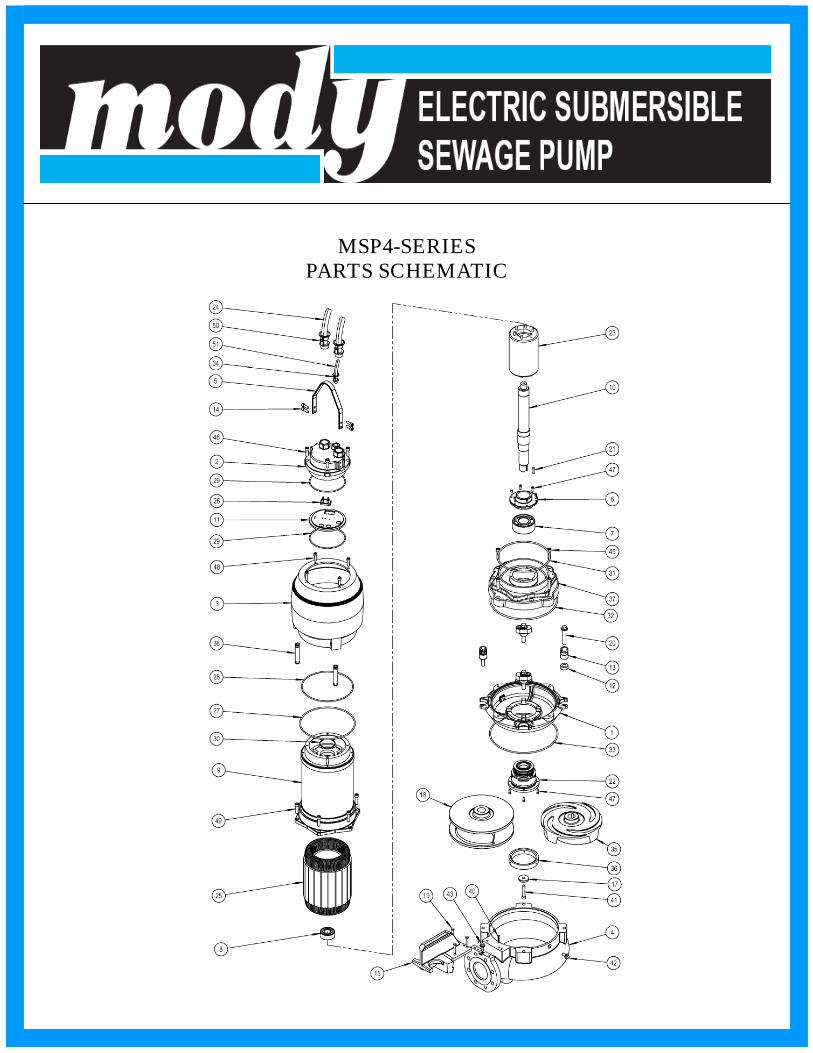
MSP4-SERIESPARTS SCHEMATIC

MSP4-SERIESPARTS LIST

MSP4-SERIESPARTS LIST