Embed Size (px)
Citation preview

MSE WALLS CASE STUDIES
by John G. Delphia, P.E.
TxDOT Bridge Division Geotechnical Branch

COMMON RETAINING WALL TYPES MSE
CONCRETE BLOCK
TEMPORARY EARTH
SPREAD FOOTING
Gabions
Drilled Shaft
Tiedback
Soil Nail
Hybrid Walls – MSE/Soil Nail
RETAINING WALL
SELECTION
FILL SITUATIONS
CUT SITUATIONS
CUT/FILL SITUATIONS
- DRILLED SHAFT - TIEDBACK - SOIL NAIL - MSE WITH SHORING - SPREAD FOOTING WITH SHORING
- DRILLED SHAFT - MSE WITH SHORING - SPREAD FOOTING WITH SHORING - HYBRID – SOIL NAIL/MSE
- MSE - CONCRETE BLOCK - SPREAD FOOTING - TEMPORARY EARTH - GABION

Wall Usage by TxDOT (August 2010 through September 2011)
Wall Type Area (ft2) % MSE 3,196,417 72 Concrete block (no r/f) 47,791 1 Cantilever drilled shaft 72,286 2 Soil Nailed 146,793 3 Rock Nailed 197,216 5 Tied-back 161,827 4 Spread footing 505,019 12 Other 22,389 1

TxDOT has had relatively few problems.

MSE WALL ISSUES • DESIGN - Global Stability - Strength Conditions - Presence of Water - Placement of Walls on Slopes
• CONSTRUCTION - Embankment/Backfill Placement - Foundation Soil Preparation - Obstructions - Damaged Reinforcements - Connections - Backfill Properties

DESIGN - Global Stability - Strength Conditions - Presence of Water - Placement of Walls on Slopes

GLOBAL STABILITY
MSE Backfill
Random Fill
Foundation Soil
MSE Backfill
Random Fill
Foundation Soil
Need to determine: -geometry -short term strength = undrained shear strength -long term strength = drained shear strength -water table


MSE WALL STANDARD
THE STRENGTH PARAMETERS SELECTED BY THE DESIGNER FOR THE GLOBAL STABILITY ANALYSIS SHOULD BE STATED IN THE PLANS IF THEY ARE DIFFERENT THEN STATED ABOVE.
Design Parameters: Design of retaining walls shall be based on the following design parameters unless stated elsewhere in the plans: Random Backfill/Foundation unit weight = 125 pcf Phi = 300 C = 0 psf

IMPORTANCE OF ACCURATE STRENGTH PARAMETERS
• Active Earth Pressure Ka = Tan2(45 – Φr/2) Φr = Random Fill Friction Angle • Foundation Friction Angle
Φf = Foundation Soil Friction Angle
• Sliding and Overturning depend upon these values.

The presence of water and its effects are important. Carefully evaluate placing a wall on a slope. May be false economy.
• Overall (global) stability and external stability (sliding, overturning, eccentricity) of every wall must be evaluated by the engineer who selects the wall (especially those on slopes).
• Short-term and Long-term conditions must be evaluated.
• Designers need to list in the plans the random fill and foundation soil strength parameters if they are different then those listed on the standard sheet.

CONSTRUCTION - Embankment/Backfill Placement

ITEM 423 Place the select and embankment backfill to the same elevation where possible, and operate the compaction equipment over the interface. Do not complete the embankment prior to construction of the retaining wall.


ITEM 423 Prevent surface water or rainwater from damaging the retaining walls during construction. Shape the backfill to prevent water from ponding or flowing on the backfill or against the wall face. Remove and replace any portion of the retaining wall damaged or moved out of tolerance by erosion, sloughing, or saturation of the retaining wall or embankment backfill.


Item 423 Place drilled shafts and piling located within the MSE volume prior to construction of the wall.
How does one compact the backfill around the abutment?
How does one compact against the embankment soil?

• Inspectors need to follow and enforce the specifications.
• The behavior of the wall is highly dependent upon the construction process

Foundation Preparation
Perform proof rolling on retaining wall foundation area to identify any loose, soft or unsuitable materials in accordance with Item 216. Material not meeting a maximum rut depth of 1 in per pass of pneumatic tired roller should continue to be rolled or removed and replaced with suitable material.
Item 423 Compact the foundation with a smooth-wheel vibratory roller or other approved roller. Remove and replace unsuitable foundation soils.

POOR PREPARATION OF RETAINING WALL FOUNDATION SOILS LEAD TO SETTLEMENT OF THE WALL

CONSTRUCTION - Obstructions Drilled Shafts Drainage Features

Wall Construction Issues
Drilled Shaft Obstructions
Need a minimum of 3’ from back of wall to face of abutment cap to facilitate wall construction


Incomplete connection with locking rod.
Soil reinforcing mat is rotated by wedging to the back of panel. This prevents bearing of the grid to the locking rod allowing potential of movement on the right side of the panel.
Panel showing movement
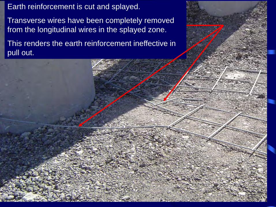
Earth reinforcement is cut and splayed.
Transverse wires have been completely removed from the longitudinal wires in the splayed zone.
This renders the earth reinforcement ineffective in pull out.

Obstructions - Drainage

Storm Sewer Parallel to Wall
Lateral with Vertical Stand Pipe
Omitted Reinforcement = Panel Movement >> Unstable Wall
Differential Movement in Backfill = Pipe Separation >> Unstable Wall
Differential Movement in Backfill = Pipe Separation >> Unstable Wall

Vertical Stand Pipe

Won’t the pipe under the leveling pad separate?
NO

?

Details for obstructions need to be: - consistent with the design in regions without obstructions - clear and should be easily constructed

TxDOT developed a shallow inlet standard 1’-10” in depth

• When inlets have to be placed behind the wall TxDOT uses the “vertical stand pipe” option and the new shallow inlet standard
• Details for obstructions need to be: - consistent with the design in regions without obstructions - clear and should be easily constructed
• Inspection is critical to ensuring the obstruction
detail is properly executed in the field

CONSTRUCTION - Damaged Reinforcements


• Inspectors need to inspect the reinforcements for potential damage
• Damaged reinforcements need to be rejected and removed from the job

CONSTRUCTION - Connections


• Inspectors need to be on the lookout for damaged connectors and to make sure the reinforcements are properly connected to the panels
TxDOT instituted the following: Panels should be rejected if:
- 25% of the total panel anchorage are damaged - Connectors are bent more than 30 degrees from
perpendicular to the panel Galvanization on a straightened connector should be restored to yield a 75 year design life

MSE WALL ISSUES
• MATERIAL - Backfill Properties

2004 Backfill Specifications TYPE SIEVE SIZE PERCENT
PASSING 3 in. 100
A ½ in. 0 – 50
No. 40 0 – 15
3 in. 100
B No. 40 0 – 60
No. 200 0 – 15
C 3 in. 100
No. 200 0 – 30
D 3 in. 100
3/8 in. 0 - 15
For Types A, B, and C if > 15% passes a No. 4 sieve the backfill is considered to be rock backfill. Resistivity > 3000 ohms-cm Chloride <100 ppm pH from 5 to 10 Sulfate <200 ppm


Backfill should be tested prior to construction and then tested using the above schedule, unless the backfill changes and then it should be tested again to make sure it meets the specifications

Improper backfill causes potential for: - reduced pullout - water pressure buildup - wall failure

• Gradation of the backfill significantly affects the performance of MSE walls.
• Backfill should be tested from an onsite stockpile and should use a wet sieve method to determine percentage of fines.
• Backfill should not break down under compaction or in the presence of water.
• Backfills with significant fine material: – have lower drained shear strength – larger lateral earth pressures – retains water and allows pore pressures to build up – can undergo large settlements.

CONCLUSIONS • TxDOT has used MSE Walls since the 80’s and they are the most
utilized wall type.
• In spite of the high use of MSE Walls, TxDOT has had relatively few issues with them.
• The issues found can be categorized into two different types: design, and construction/inspection.
• TxDOT has reviewed and analyzed all the issues to better understand why they occurred and what caused them.
• The lessons learned from the issues observed have helped TxDOT to formulate corrective actions (workshops, presentations, updated specifications, etc.) to help prevent future problems.
• Treat the construction of the walls as a structure (bridge) not as an embankment

QUESTIONS?