Embed Size (px)
DESCRIPTION
This manual describes the numerous features of MSC.FlightLoads and Dynamics.The guide is organized to emphasize the graphical nature of MSC.FlightLoads and Dynamics and discusses each of the system modules.
Citation preview
MSC.FlightLoads
MSC.FlightLoads and Dynamics User’s GuideVersion 2006

Corporate MSC.Software Corporation815 Colorado BoulevardLos Angeles, CA 90041-1777Telephone: (323) 258-9111 or (800) 336-4858FAX: (323) 259-3638
EuropeMSC.Software CorporationInnsbrucker Ring 15Postfach 80 12 4081612 Munchen, GERMANYTelephone: (49) (89) 431 9870Fax: (49) (89) 436 1716
Asia PacificMSC.Software CorporationEntsuji-Gadelius Building2-39, Akasaka 5-chomeMinato-ku, Tokyo 107, JAPANTelephone: (81) (03) 3505-0266Fax: (81) (03) 3505-0914
Worldwide Webwww.mscsoftware.com
Disclaimer
MSC.Software Corporation reserves the right to make changes in specifications and other information contained in this document without prior notice.
The concepts, methods, and examples presented in this text are for illustrative and educational purposes only, and are not intended to be exhaustive or to apply to any particular engineering problem or design. MSC.Software Corporation assumes no liability or responsibility to any person or company for direct or indirect damages resulting from the use of any information contained herein.
User Documentation: Copyright 2006 MSC.Software Corporation. Printed in U.S.A. All Rights Reserved.
This notice shall be marked on any reproduction of this documentation, in whole or in part. Any reproduction or distribution of this document, in whole or in part, without the prior written consent of MSC.Software Corporation is prohibited.
MSC is a registered trademark of MSC.Software Corporation. Nastran is a registered trademark of the National Aeronautics and Space Administration. MSC.Nastran is an enhanced proprietary version developed and maintained by MSC.Software Corporation. MSC.Patran is a trademark of MSC.Software Corporation.
MSC.FlightLoads and Dynamics is a trademark of MSC.Software Corporation. AIX and MVS are registered trademarks of the International Business Machines Corporation. UNIX is a trademark of American Telephone and Telegraph Company.
C O N T E N T SMSC.FlightLoads and Dynamics User’s Guide
CloseOptionsMSC.FlightLoads and Dynamics User’s GuideContents iii Options
MSC.FlightLoads and Dynamics User’s Guide,
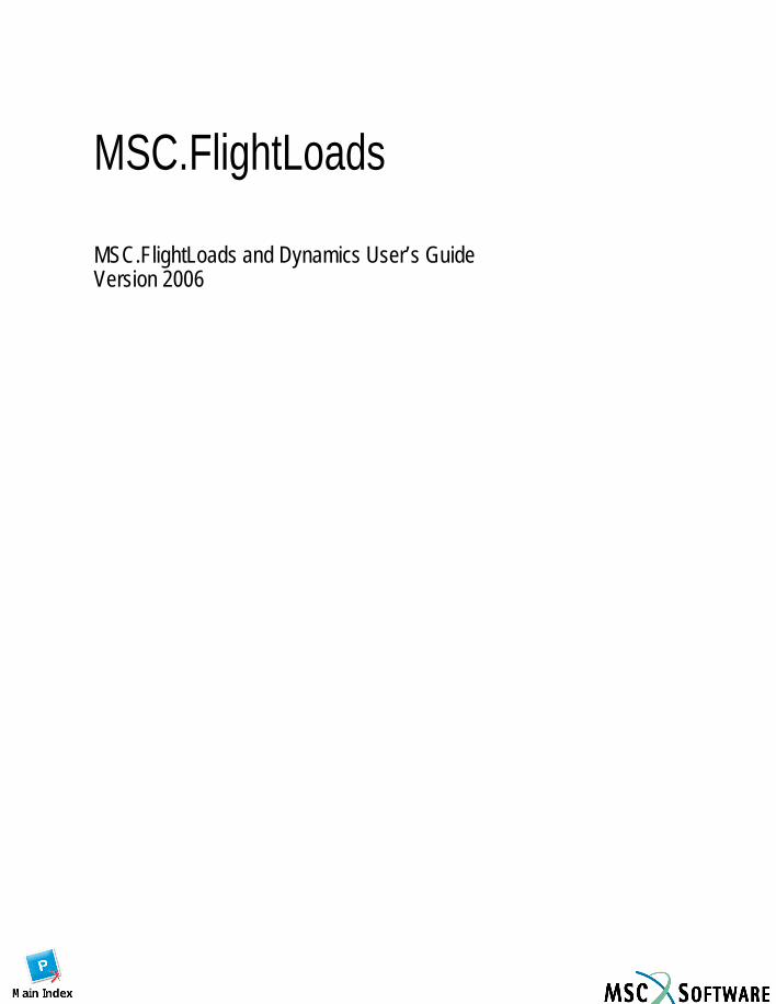
1Introduction Loads in the Design of Flight Vehicles, 2
Background, 2 MSC’s Initiative, 2
Architecture and Capabilities, 3
Integration of MSC.Nastran and MSC.Patran, 4
About This Guide, 5
2Getting Started Prerequisites, 8
Software, 8 Experience, 8 Structural Model, 8
Terms, 9
Invoking MSC.FlightLoads and Dynamics, 10 Aero Modeling, 12
Graphical User Interface, 13 Working with FlightLoads Forms, 13 Working with Subforms, 14
3Aero Modeling Introduction, 18
Aero Modeling Options , 19
Model Management , 20 Overview, 20
- Definitions for the Model Management Objects, 21 Model Management Forms, 22
- SuperGroup Forms, 23- Aero Groups Forms, 27- Orphan Groups Forms, 28
Flat Plate Aero Modeling , 29 Overview, 29
- Definitions for the Flat Plate Aero Modeling Objects, 30- Flat Plate Aero Modeling Forms, 30
Lifting Surface Methods, 32 Lifting Surface Forms, 33
- Create/Lifting Surface/Existing Surface, 33
C O N T E N T SMSC.FlightLoads and Dynamics User’s Guide
CloseOptionsMSC.FlightLoads and Dynamics User’s GuideContents iv Options
- Create/Lifting Surface/4 Points, 34- Create/Lifting Surface/2 Curve/Edge, 35- Create/Lifting Surface/2 Points/Chord, 36- Create/Lifting Surface Subforms, 37- Delete/Lifting Surface, 42- Modify/Lifting Surface, 43- , 46- Show/Lifting Surface/Mesh, 46- Show/Lifting Surface/Aspect Ratio, 47- Show/Lifting Surface/Boxes/Wave, 48- Fringe Attributes, 51
Body Forms, 52- Z Body, Y Body and ZY Body, 52- Create/Body/Existing Curve, 53- Create/Body/2 Points, 54- Create/Body/Point-Body, 55- Create/Body Subforms, 56- Modify/Body, 60- Delete/Body, 62- Show/Body/Attributes, 63- Show/Body/Mesh, 65- Show/Body/Interference, 66- Show/Body/Slender, 67
Delete/Any, 68- Modify/Any, 69- Show/Model Info, 70- Show/All Model Information, 71
Control Device, 72 Overview, 72 Control Devices, 73
- Control Device Forms, 74- Create/Control Surfaces/Linear, 75- Create/Control Surfaces /Nonlinear, 77- Create/Control Surfaces Subforms, 78- Create/General Controls, 81- Delete/Any, 82- Delete/Angles and Rates, 82- Delete/Control Surfaces, 83- Delete/General Controls, 83- Modify/Angles and Rates, 84- Modify/Control Surfaces/Linear, 85- Modify/Control Surfaces/Nonlinear, 86- Modify/General Controls, 87- Show/Control Surfaces/Attributes, 88- Show Attribute Information, 89- Show/Any Controllers, 90
C O N T E N T SMSC.FlightLoads and Dynamics User’s Guide
CloseOptionsMSC.FlightLoads and Dynamics User’s GuideContents v Options
- Show/Any Controllers/Show Controller Info, 90
Aero Monitor Points, 92 Overview, 92
- Definitions for Aero Monitor Points, 92- Create/Monitor Points, 93- Aero Monitor Point Info, 97
4Aerodynamics Introduction, 100
Global Data, 101
Steady Aerodynamics, 102- Overview, 102
Steady Aerodynamics, 102- Create/Pressure/Q, 104- Create/Normalwash/Q, 105- Create/Force/Q, 106- Create/Any Subforms, 107- FEM Dependent Data, 108- Delete/Any, 109- Modify/Pressure/Q, 110- Modify/Normalwash/Q, 111- Modify/Force/Q, 112- Show/Any/Fringe, 113- Show/Any/Fringe /Fringe Attributes, 114
Unsteady Aerodynamics, 115 Overview, 116 Unsteady Aerodynamics, 116 Create/MK Pair Set, 117 Delete/MK Pair Set, 118 Modify/MK Pair Set, 119 Mach-Frequency Pairs/Subforms, 120
- Mach-Frequency Pairs/Uniform/NonDimensional, 120- Mach-Frequency Pairs/Uniform/Dimensional, 122- Mach-Frequency Pairs/One Way Bias/NonDimensional, 123- Mach-Frequency Pairs/One Way Bias/Dimensional, 124- Mach-Frequency Pairs/Tabular, 125
5Aeroelasticity Introduction, 128
Aero-Structure Coupling, 129
C O N T E N T SMSC.FlightLoads and Dynamics User’s Guide
CloseOptionsMSC.FlightLoads and Dynamics User’s GuideContents vi Options
Overview, 129 Aero-Structure Coupling, 130
- Create/Surface (General, Displacement, or Force), 131- Create/Surface Subforms, 133- Create/Beam (General, Displacement, or Force) Aero Body, 136- Create/Beam (General, Displacement, or Force) Aero Surface, 138- Create/Beam Subforms, 139
Delete Any, Surface or Beam, 142- Modify/Surface (General, Displacement, or Force), 143- Modify/Beam (General, Displacement, or Force), 144
Show Surface or Beam/Attributes, 145- Show Attribute Information, 146- Verify/Displacement/Plot, 147
Structural Monitor Points, 148 Overview, 148 Structural Monitor Points, 148 Create/Monitor Points, 149
- Monitor Point Definition, 150 Delete Monitor Points, 151 Modify Monitor Points, 152 Show/Structural Monitor Points, 153 Structural Monitor Point Info, 153
Aeroelastic Model, 154 Aeroelastic Model Form , 155
- Aeroelastic Model Subforms, 156
Analysis, 161 Overview, 161 Analysis Forms, 161 Aeroelastic Analysis, 162
- Target Database , 164- Subcase Create - (for Static Aeroelasticity) - Create, 167- Subcase Create - (for Static Aeroelasticity) - Delete, 168- Subcase Create - (for Static Aeroelasticity) - Global Data, 169- Trim Parameters , 170- Subcase Create - (for Flutter) - Delete, 180- Subcase Create - (for Flutter) - Global Data, 180- Mach/Frequency Pairs, 181
Flutter Parameters, 182- Subcase Select , 190- Existing Jobs , 191- Translation Parameters, 193
C O N T E N T SMSC.FlightLoads and Dynamics User’s Guide
CloseOptionsMSC.FlightLoads and Dynamics User’s GuideContents vii Options
6Results Browser Introduction, 200
Attach Results Data , 201 Overview, 201 Attach Results Data, 202
- Attach XDB, 203- Translation Parameters Subform, 204- Attach Aero, 205- Detach XDB, 206
Flexible Increment Filter, 207
Loads Browsers, 208 Overview, 208
- Loads Browser, 209 Create/Region, 211 Create/Region Chain, 212 Create/Force, 213 Modify/Region, 216 Modify/Region Chain, 217 Delete/Region, 218 Delete/Region Chain, 219 Plot, 220 Plot Running Loads, 220 Running Loads - Methodology, 221 Plot/LBCs/Running Loads, 225 One or more MSC.Patran Loads/Boundary Conditions can be integrated
over a model to produce a Running Load plot., 225 Plot/Load Cases/Running Loads, 227 Plot/Results/Running Loads, 228 Plot Running Loads - Plot Options, 229 Plot Load Summation, 230
- Load Summation - Methodology, 230 Plot/LBCs/Load Summation, 232 Plot Load Summation - Plot Options, 234
Export , 236 Overview, 236 Export, 237
- Export - Output File Name Subform, 238
Results Viewer, 239
C O N T E N T SMSC.FlightLoads and Dynamics User’s Guide
CloseOptionsMSC.FlightLoads and Dynamics User’s GuideContents viii Options
7Import/Export Introduction, 242
Import, 243
Export, 245 Overview, 245 Export, 245 Export/Load Set/Results, 247
- Select File Subform, 248 BDF Fragments, 249
- Export/BDF Fragments/Aero Groups, 250- Export/BDF Fragments/Super Groups, 251- Export/BDF Fragments/Aero Elem List, 252- Export/BDF Fragments/Grid Set, 253- Export/BDF Fragments/Splines, 254- Export/BDF Fragments/Control Devices, 255- Export/BDF Fragments/Coord Frame, 256- Export/BDF Fragments/Monitor Points, 257- Select File Subform, 258- Select Surface/Select Groups Subform, 259
APanel Aerodynamics
Introduction, 262
Aerodynamic Data Generation, 263
Aerodynamic Theories, 264 Doublet-Lattice Subsonic Lifting Surface Theory, 265 ZONA51 Supersonic Lifting Surface Theory, 266 Subsonic Wing-Body Interference Theory, 267
Aerodynamic Modeling Guidelines, 268 Doublet-Lattice and ZONA51 Panels, 269 Spanwise Convergence Criteria, 271 Slender and Interference Bodies, 273
C O N T E N T SMSC.FlightLoads and Dynamics User’s Guide
CloseOptionsMSC.FlightLoads and Dynamics User’s GuideContents ix Options
BSplines Introduction, 278
Theoretical Development, 280 Infinite Plate Spline and the Linear Spline, 280 Thin Plate Spline, 280 Two Dimensional Finite Plate Spline, 284 Spring Attachments and Interpolation Smoothing, 287
Guidelines, 288
Spline Metrics, 292
CResults Interface via XDB
XDB Output, 294
DAerodynamic and Aeroelastic Databases
Aerodynamic and Aeroelastic Databases, 300 Paths, 300 Aerodynamic Database, 301 Aeroelastic Database, 303 Inputs and Outputs, 303 Guidelines and Limitations, 305 Examples, 305
EStatic Aeroelastic Analysis
Introduction, 308
Aeroelastic Matrices, 309
Aeroelastic Solutions, 311 Restrained Analysis (Displacements Relative to ), 311 Restrained Stability Derivatives from the Unit Solutions, 314 Unrestrained Analysis and Stability Derivatives (Displacements Relative to
Mean Axis), 315 Recovery of Unit Solutions to the a-set and to the k-set, 319 Distributed Force Increments from Unit Solutions, 320
Printed Output, 321
C O N T E N T SMSC.FlightLoads and Dynamics User’s Guide
CloseOptionsMSC.FlightLoads and Dynamics User’s GuideContents x Options
Stability Derivatives and Hinge Moment Coefficients, 321 HP and HP0 Matrices, 325 Trim Results and Control Surface Limits, 326 Pressure and Forces on the Aerodynamic Elements, 328
FAero Mesh Interface File Format
Introduction, 330
Definition of an Aerodynamic Mesh Interface File (AMIF), 331 General Rules, 331
- Entry: Comment, 331- Entry: SGROUP (Required), 332- Entry: AGROUP, 332- Entry: ADOF (Required), 333- Entry: ACORD, 333- Entry: AECORD, 334- Entry: AGRID, 334- Entry: EIDSTART, 335- Entry: AQUAD, 336- Entry: ATRIA, 337
AMIF Format and Reading, 338
Sample AMI File, 339References References, 346
INDEX MSC.FlightLoads and Dynamics User’s Guide 347

CloseOptionsMSC.FlightLoads and Dynamics User’s GuideIntroduction § 1 Options
MSC.FlightLoads and Dynamics User’s Guide
CHAPTER
1 Introduction
Loads in the Design of Flight Vehicles
Architecture and Capabilities
Integration of MSC.Nastran and MSC.Patran
About This Guide

CloseOptionsMSC.FlightLoads and Dynamics User’s GuideIntroduction §1.1 2 Options
1.1 Loads in the Design of Flight Vehicles
BackgroundThe calculation of flight loads is a critical part of air vehicle design. The structural design can only occur once the representative loads are provided to the designer. On the other hand, the prediction of accurate loads is a sophisticated and complex process that requires skilled and experienced engineers. They must integrate results from wind tunnel tests, computer simulations, historical data and empirical formulations into a number of loads cases that provide a realistic assessment of the flight vehicle’s environment. Under these conditions, the vehicle must satisfy requirements imposed by regulatory agencies as part of the vehicle certification process.
Given the complexity and importance of the loads calculation, it has become a truism in air vehicle design that “the loads are always late.” This means that the quantification of the loads is on the critical path in the development of a new or modified vehicle. It also implies that inaccurate initial loads that are corrected or updated after completion of the original structural design can have a serious negative effect on the overall development schedule. In the worst case, if the inaccurate loads are not detected until after the vehicle has entered flight testing, very costly redesign and retrofitting may have to occur or vehicle placards may be established to limit certain maneuvers, thus reducing operational performance.
MSC’s InitiativeDue to their long history of successful application development for the aerospace industry, MSC.Software has repeatedly been asked to assist in the development of an advanced flight loads calculation system. MSC.Software’s core MSC.Nastran and MSC.Patran products were developed to address analysis and design requirements for aerospace applications. MSC.Software first introduced an aeroelastic capability into MSC.Nastran in 1974, and this has been continuously maintained and enhanced.
Starting in late 1996, MSC.Software assembled a development team dedicated to creating a system for providing timely and accurate flight loads information. This User’s Guide documents the current release of MSC.FlightLoads and Dynamics.
CloseOptionsMSC.FlightLoads and Dynamics User’s GuideIntroduction §1.2 3 Options
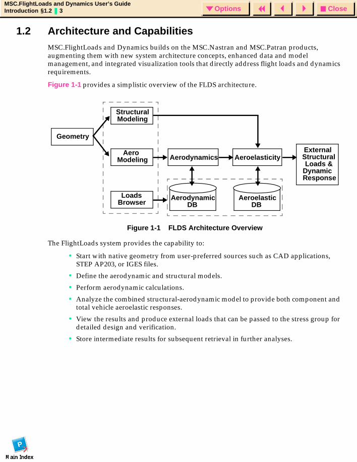
1.2 Architecture and CapabilitiesMSC.FlightLoads and Dynamics builds on the MSC.Nastran and MSC.Patran products, augmenting them with new system architecture concepts, enhanced data and model management, and integrated visualization tools that directly address flight loads and dynamics requirements.
Figure 1-1 provides a simplistic overview of the FLDS architecture.
Figure 1-1 FLDS Architecture Overview
The FlightLoads system provides the capability to:
• Start with native geometry from user-preferred sources such as CAD applications, STEP AP203, or IGES files.
• Define the aerodynamic and structural models.
• Perform aerodynamic calculations.
• Analyze the combined structural-aerodynamic model to provide both component and total vehicle aeroelastic responses.
• View the results and produce external loads that can be passed to the stress group for detailed design and verification.
• Store intermediate results for subsequent retrieval in further analyses.
StructuralModeling
AeroModeling
LoadsBrowser
Geometry
Aerodynamics AeroelasticityExternal StructuralLoads &
AerodynamicDB
AeroelasticDB
DynamicResponse
CloseOptionsMSC.FlightLoads and Dynamics User’s GuideIntroduction §1.3 4 Options
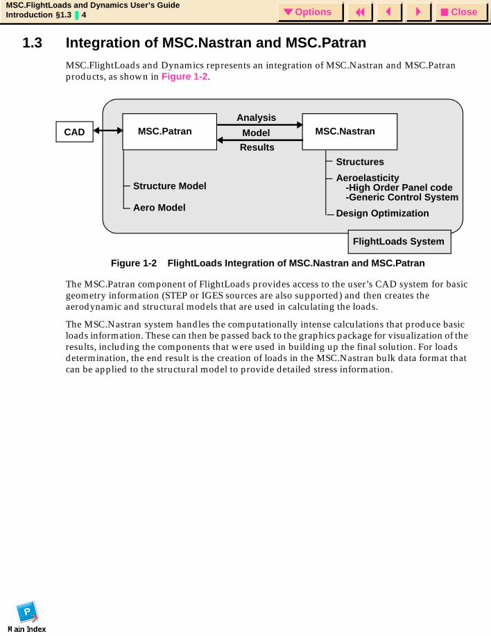
1.3 Integration of MSC.Nastran and MSC.PatranMSC.FlightLoads and Dynamics represents an integration of MSC.Nastran and MSC.Patran products, as shown in Figure 1-2.
Figure 1-2 FlightLoads Integration of MSC.Nastran and MSC.Patran
The MSC.Patran component of FlightLoads provides access to the user’s CAD system for basic geometry information (STEP or IGES sources are also supported) and then creates the aerodynamic and structural models that are used in calculating the loads.
The MSC.Nastran system handles the computationally intense calculations that produce basic loads information. These can then be passed back to the graphics package for visualization of the results, including the components that were used in building up the final solution. For loads determination, the end result is the creation of loads in the MSC.Nastran bulk data format that can be applied to the structural model to provide detailed stress information.
CAD
Analysis
Model
Results
Structures
Aeroelasticity-High Order Panel code-Generic Control System
Design Optimization
Structure Model
Aero Model
FlightLoads System
MSC.NastranMSC.Patran

CloseOptionsMSC.FlightLoads and Dynamics User’s GuideIntroduction §1.4 5 Options
1.4 About This GuideThis User’s Guide describes in detail the numerous features of MSC.FlightLoads and Dynamics. The guide is organized to emphasize the graphical nature of MSC.FlightLoads and Dynamics. Following this Introduction there is an overview section, “Getting Started,” that sets the stage for the remaining chapters, which lead the user through each of the system modules.
Separate chapters discuss:
• Aero Modeling
• Aerodynamics
• Aeroelasticity
• Results Browser
• Import/Export
Appendices provide theoretical and user information on the solutions central to the aeroelastic analyses, including the following:
• Panel Aerodynamics
• Splines
• Results Interface via XDB
• Aerodyanmic and Aeroelastic Databases
• Static Aeroelastic Analysis
• MSC.Nastran Input File
This document is intended to provide a thorough introduction to MSC.FlightLoads and Dynamics, but it can address only a small fraction of the issues that are invoked by the system. MSC has many other related documents and the user is advised to search out these relevant publications. Two especially important ones are:
• MSC.Nastran Aeroelastic Analysis User’s Guide
• MSC.Patran User’s Guide
The MSC Bookstore is on the World Wide Web at www.mscsoftware.com; select the engineering-e.com tab and the BooksMart button to display a comprehensive list of publications available from MSC.Software.

CloseOptionsMSC.FlightLoads and Dynamics User’s GuideIntroduction §1.4 6 Options

CloseOptionsMSC.FlightLoads and Dynamics User’s GuideGetting Started § 7 Options
MSC.FlightLoads and Dynamics User’s Guide
CHAPTER
2 Getting Started
Prerequisites
Terms
Invoking MSC.FlightLoads and Dynamics
Graphical User Interface
CloseOptionsMSC.FlightLoads and Dynamics User’s GuideGetting Started §2.1 8 Options
2.1 Prerequisites
SoftwareMSC.FlightLoads and Dynamics is based on MSC.Nastran and MSC.Patran. The MSC.Nastran code must include the Aero I option. If supersonic analyses are of interest, it is also necessary to have Aero II. The MSC.Patran code must include the MSC.Nastran Preference.
ExperienceIt is assumed that the MSC.FlightLoads user has some experience with both the underlying software and the analysis procedures involved in the system. It is also expected that the user has basic familiarity with flight loads concepts such as rigid and elastic loads, stability derivatives, control surfaces, maneuvers and other similar concepts. Some familiarity with static aeroelasticity in MSC.Nastran (SOL 144) and flutter in MSC.Nastran (SOL 145) is beneficial.
Structural ModelOne of the components of an aeroelastic model in MSC.FlightLoads and Dynamics is the structural model. In this manual, these structural models are presumed to exist. They can enter the MSC.FlightLoads and Dynamics system by import or by direct creation in MSC.FlightLoads and Dynamics (MSC.Patran) using the structures preference. This manual does not cover any structural modeling issues. Please refer to the MSC.Nastran Preference of MSC.Patran for information on structural modeling.
CloseOptionsMSC.FlightLoads and Dynamics User’s GuideGetting Started §2.2 9 Options
2.2 TermsThe following is a list of various terms and acronyms that you will need to know when using the MSC.FlightLoads and Dynamics system and this manual.
FLD - MSC.FlightLoads and Dynamics
kmin - Minimum Reduced Frequency
kmax - Maximum Reduced Frequency
Fmin - Minimum Cyclic Frequency
Fmax - Maximum Cyclic Frequency
Vmin - Minimum Velocity
Vmax - Maximum Velocity
v - velocity in consistent length units (length/s)
c - reference chord
b - reference span
S - reference area
- radian frequency
s - seconds
g - acceleration due to gravity in consistent length units (length/s/s)
dimensionless rate = for anti-symmetric; or for symmetric
ω
ωb2v------- ωc
2v-------
CloseOptionsMSC.FlightLoads and Dynamics User’s GuideGetting Started §2.3 10 Options
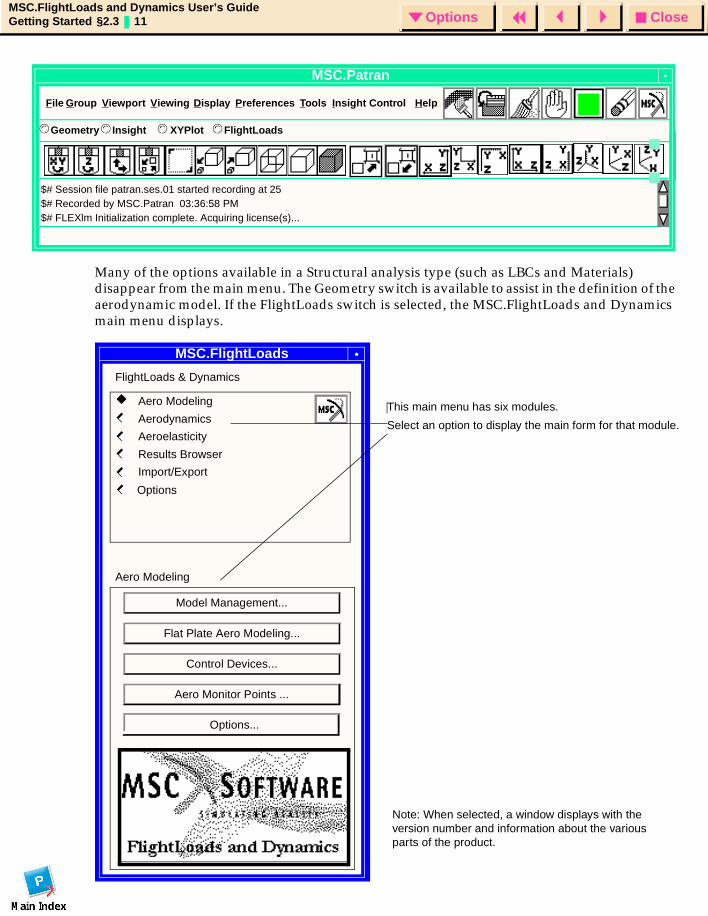
2.3 Invoking MSC.FlightLoads and Dynamics MSC.FlightLoads and Dynamics is invoked using the p3fld or the mscfld command. These two commands are the same as the command that invokes MSC.Patran except that it uses the -ifile option to replace the use of the init.pcl file with the init_fld.pcl file that MSC.FlightLoads and Dynamics needs. This displays the familiar MSC.Patran main form. Users can still run MSC.Patran from these two commands.
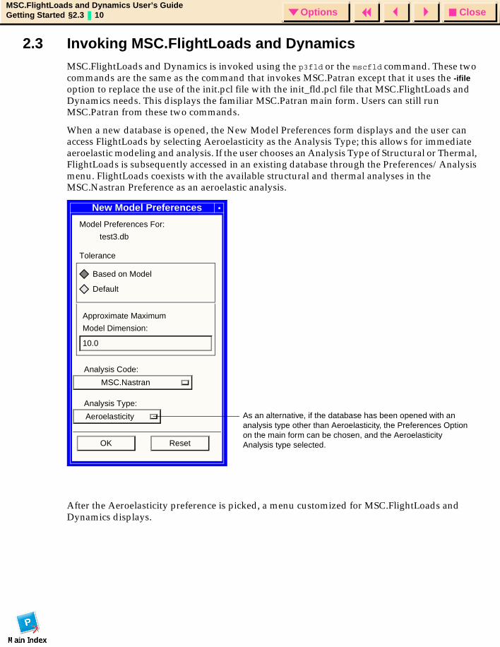
When a new database is opened, the New Model Preferences form displays and the user can access FlightLoads by selecting Aeroelasticity as the Analysis Type; this allows for immediate aeroelastic modeling and analysis. If the user chooses an Analysis Type of Structural or Thermal, FlightLoads is subsequently accessed in an existing database through the Preferences/Analysis menu. FlightLoads coexists with the available structural and thermal analyses in the MSC.Nastran Preference as an aeroelastic analysis.
After the Aeroelasticity preference is picked, a menu customized for MSC.FlightLoads and Dynamics displays.
New Model Preferences
Model Preferences For:
test3.db
Tolerance
Based on Model
Default
Approximate Maximum
Model Dimension:
10.0
Analysis Code:
MSC.Nastran
Analysis Type:
Aeroelasticity
OK Reset
As an alternative, if the database has been opened with an analysis type other than Aeroelasticity, the Preferences Option on the main form can be chosen, and the Aeroelasticity Analysis type selected.
CloseOptionsMSC.FlightLoads and Dynamics User’s GuideGetting Started §2.3 11 Options
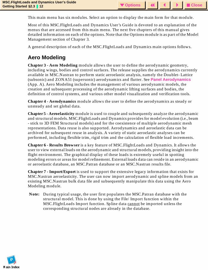
Many of the options available in a Structural analysis type (such as LBCs and Materials) disappear from the main menu. The Geometry switch is available to assist in the definition of the aerodynamic model. If the FlightLoads switch is selected, the MSC.FlightLoads and Dynamics main menu displays.
MSC.Patran
$# Session file patran.ses.01 started recording at 25$# Recorded by MSC.Patran 03:36:58 PM$# FLEXlm Initialization complete. Acquiring license(s)...
File Group Viewport Display Preferences Tools Help
Geometry© Insight XYPlot FlightLoads© ©©
Viewing Insight Control
MSC/FL&DSMSC.FlightLoads
FlightLoads & Dynamics
Aero Modeling
Aerodynamics
Aeroelasticity
Results Browser
Import/Export
Aero Modeling
Model Management...
Flat Plate Aero Modeling...
Control Devices...
Aero Monitor Points ...
Note: When selected, a window displays with the version number and information about the various parts of the product.
Options
This main menu has six modules.
Select an option to display the main form for that module.
Options...
CloseOptionsMSC.FlightLoads and Dynamics User’s GuideGetting Started §2.3 12 Options
This main menu has six modules. Select an option to display the main form for that module.
Most of this MSC.FlightLoads and Dynamics User’s Guide is devoted to an explanation of the menus that are accessed from this main menu. The next five chapters of this manual gives detailed information on each of the options. Note that the Options module is as part of the Model Management section of Chapter 3.
A general description of each of the MSC.FlightLoads and Dynamics main options follows.
Aero ModelingChapter 3 - Aero Modeling module allows the user to define the aerodynamic geometry, including wings, bodies and control surfaces. The release supplies the aerodynamics currently available in MSC.Nastran to perform static aeroelastic analysis, namely the Doublet- Lattice (subsonic) and ZONA51 (supersonic) aerodynamics and flutter. See Panel Aerodynamics (App. A). Aero Modeling includes the management of various aerodynamic models, the creation and subsequent processing of the aerodynamic lifting surfaces and bodies, the definition of control systems, and various other model visualization and verification tools.
Chapter 4 - Aerodynamics module allows the user to define the aerodynamics as steady or unsteady and set global data.
Chapter 5 - Aeroelasticity module is used to couple and subsequently analyze the aerodynamic and structural models. MSC.FlightLoads and Dynamics provides for model evolution (i.e., beam - stick to 3D FEM Structural models) and for the coexistence of multiple aerodynamic mesh representations. Data reuse is also supported. Aerodynamics and aeroelastic data can be archived for subsequent reuse in analysis. A variety of static aeroelastic analyses can be performed, including flexible trim, rigid trim and the calculation of flexible load increments.
Chapter 6 - Results Browser is a key feature of MSC.FlightLoads and Dynamics. It allows the user to view external loads on the aerodynamic and structural models, providing insight into the flight environment. The graphical display of these loads is extremely useful in spotting modeling errors or areas for model refinement. External loads data can reside in an aerodynamic or aeroelastic database, an MSC.Patran database or an MSC.Nastran results file.
Chapter 7 - Import/Export is used to support the extensive legacy information that exists for MSC.Nastran aeroelasticity. The user can now import aerodynamic and spline models from an existing MSC.Nastran bulk data file and subsequently manipulate this data using the Aero Modeling module.
Note: During typical usage, the user first populates the MSC.Patran database with the structural model. This is done by using the File/Import function within the MSC.FlightLoads Import function. Spline data cannot be imported unless the corresponding structural nodes are already in the database.
CloseOptionsMSC.FlightLoads and Dynamics User’s GuideGetting Started §2.4 13 Options
2.4 Graphical User Interface The previous section introduced the high level MSC.FlightLoads and Dynamics menus. This section provides a brief general description of the use of forms in the system. The conventions discussed here are those of MSC.Patran.
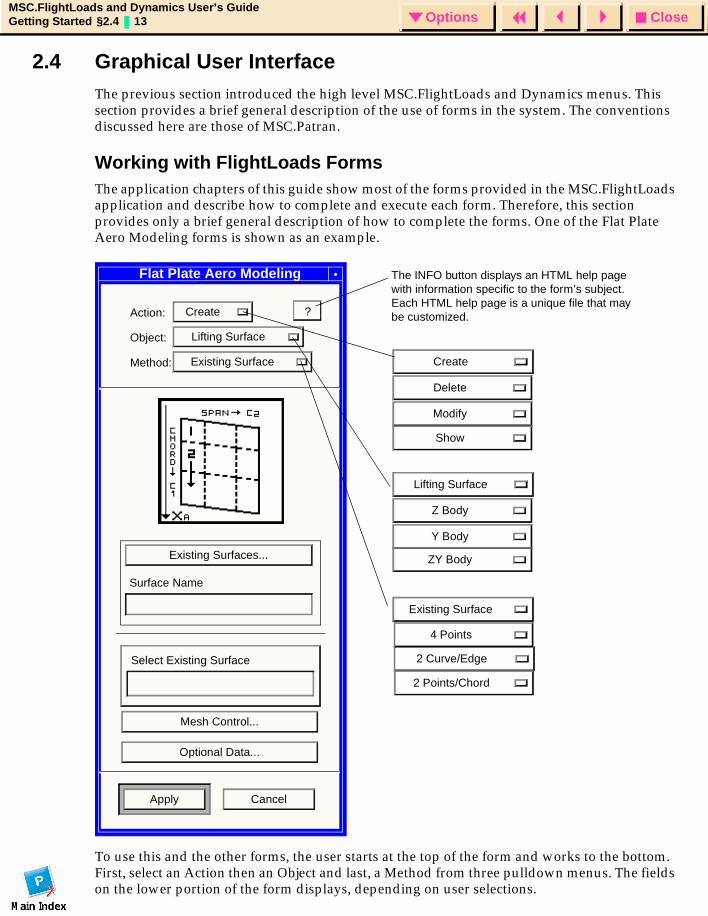
Working with FlightLoads FormsThe application chapters of this guide show most of the forms provided in the MSC.FlightLoads application and describe how to complete and execute each form. Therefore, this section provides only a brief general description of how to complete the forms. One of the Flat Plate Aero Modeling forms is shown as an example.
To use this and the other forms, the user starts at the top of the form and works to the bottom. First, select an Action then an Object and last, a Method from three pulldown menus. The fields on the lower portion of the form displays, depending on user selections.
Flat Plate Aero Modeling
Action: Create
Object: Lifting Surface
Method: Existing Surface
Existing Surfaces...
Surface Name
Select Existing Surface
Mesh Control...
Optional Data...
Apply Cancel
?
Create
Delete
Modify
Show
Lifting Surface
Z Body
Y Body
ZY Body
2 Curve/Edge
Existing Surface
4 Points
2 Points/Chord
The INFO button displays an HTML help page with information specific to the form’s subject. Each HTML help page is a unique file that may be customized.
CloseOptionsMSC.FlightLoads and Dynamics User’s GuideGetting Started §2.4 14 Options
To complete the fields in the lower portion of the form, the user may either click on toggle buttons, select from pulldown menus, type surface names and IDs or other numerical data, depending on the requested information. Special selection menus also display to help select entities in the viewport; this displays their numeric IDs in the currently selected form field. After all the fields on the form are completed, click on Apply to execute the desired operation.
Working with SubformsClicking on an ellipsis field (those that end with “...”) displays a subform. The available subforms from the Create/Lifting Surface form are shown on the preceding page.
• Existing Surfaces
• Mesh Control
• Optional Data
Each of these subforms allows input of additional data. The layout of the subforms is unique to the requested data and typically does not follow the standard Action/Object/Method convention.
CloseOptionsMSC.FlightLoads and Dynamics User’s GuideGetting Started §2.4 15 Options
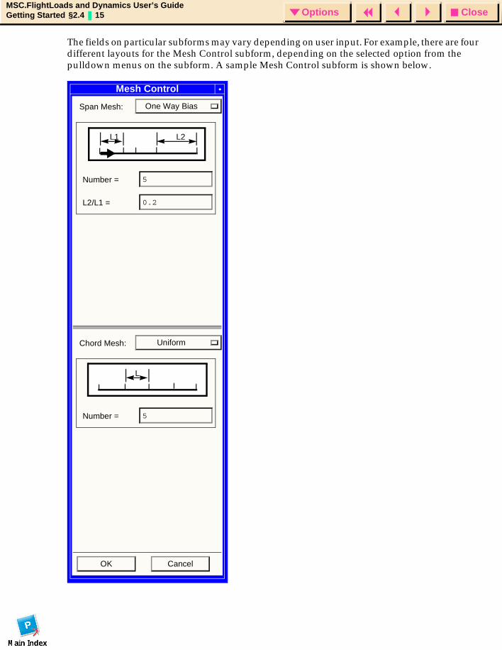
The fields on particular subforms may vary depending on user input. For example, there are four different layouts for the Mesh Control subform, depending on the selected option from the pulldown menus on the subform. A sample Mesh Control subform is shown below.
Mesh Control
Span Mesh: One Way Bias
Number = 5
L2/L1 = 0.2
Chord Mesh: Uniform
Number = 5
OK Cancel
L1 L2
L

CloseOptionsMSC.FlightLoads and Dynamics User’s GuideGetting Started §2.4 16 Options
CloseOptionsMSC.FlightLoads and Dynamics User’s GuideAero Modeling § 17 Options
MSC.FlightLoads and Dynamics User’s Guide
CHAPTER
3 Aero Modeling
Introduction
Aero Modeling Options
Model Management
Flat Plate Aero Modeling
Control Device
Aero Monitor Points
CloseOptionsMSC.FlightLoads and Dynamics User’s GuideAero Modeling §3.1 18 Options
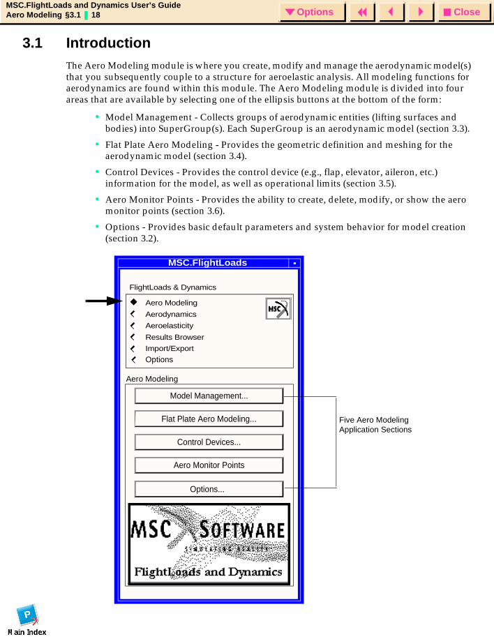
3.1 IntroductionThe Aero Modeling module is where you create, modify and manage the aerodynamic model(s) that you subsequently couple to a structure for aeroelastic analysis. All modeling functions for aerodynamics are found within this module. The Aero Modeling module is divided into four areas that are available by selecting one of the ellipsis buttons at the bottom of the form:
• Model Management - Collects groups of aerodynamic entities (lifting surfaces and bodies) into SuperGroup(s). Each SuperGroup is an aerodynamic model (section 3.3).
• Flat Plate Aero Modeling - Provides the geometric definition and meshing for the aerodynamic model (section 3.4).
• Control Devices - Provides the control device (e.g., flap, elevator, aileron, etc.) information for the model, as well as operational limits (section 3.5).
• Aero Monitor Points - Provides the ability to create, delete, modify, or show the aero monitor points (section 3.6).
• Options - Provides basic default parameters and system behavior for model creation (section 3.2).
MSC/FL&DSMSC.FlightLoads
Model Management...
Flat Plate Aero Modeling...
Control Devices...
Aero Monitor Points
FlightLoads & Dynamics
Aero Modeling
Aerodynamics
Aeroelasticity
Results Browser
Import/Export
Options
Five Aero Modeling Application Sections
Options...
Aero Modeling
CloseOptionsMSC.FlightLoads and Dynamics User’s GuideAero Modeling §3.2 19 Options
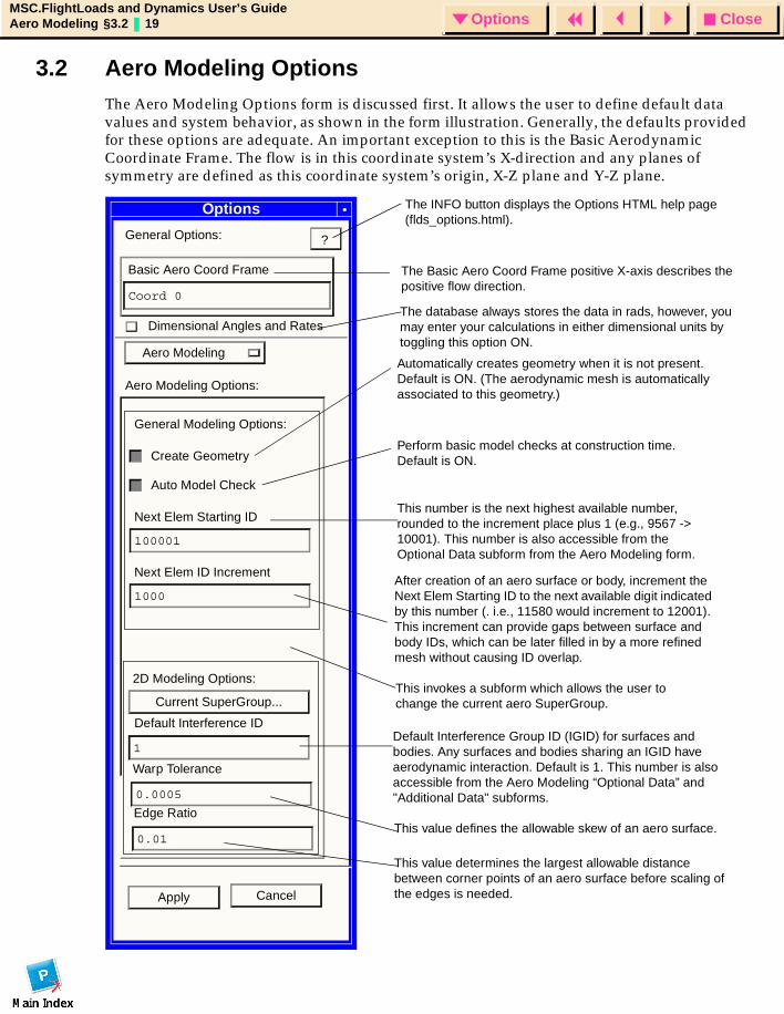
3.2 Aero Modeling Options The Aero Modeling Options form is discussed first. It allows the user to define default data values and system behavior, as shown in the form illustration. Generally, the defaults provided for these options are adequate. An important exception to this is the Basic Aerodynamic Coordinate Frame. The flow is in this coordinate system’s X-direction and any planes of symmetry are defined as this coordinate system’s origin, X-Z plane and Y-Z plane.
Options
General Options:
Basic Aero Coord Frame
Coord 0
Aero Modeling
Aero Modeling Options:
General Modeling Options:
Create Geometry
Auto Model Check
Next Elem Starting ID
100001
Next Elem ID Increment
1000
Current SuperGroup...
Default Interference ID
1
Apply Cancel
?
Automatically creates geometry when it is not present. Default is ON. (The aerodynamic mesh is automatically associated to this geometry.)
Perform basic model checks at construction time. Default is ON.
This number is the next highest available number, rounded to the increment place plus 1 (e.g., 9567 -> 10001). This number is also accessible from the Optional Data subform from the Aero Modeling form.
After creation of an aero surface or body, increment the Next Elem Starting ID to the next available digit indicated by this number (. i.e., 11580 would increment to 12001). This increment can provide gaps between surface and body IDs, which can be later filled in by a more refined mesh without causing ID overlap.
This invokes a subform which allows the user to change the current aero SuperGroup.
Default Interference Group ID (IGID) for surfaces and bodies. Any surfaces and bodies sharing an IGID have aerodynamic interaction. Default is 1. This number is also accessible from the Aero Modeling “Optional Data” and "Additional Data" subforms.
The Basic Aero Coord Frame positive X-axis describes the positive flow direction.
The INFO button displays the Options HTML help page (flds_options.html).
0.01
0.0005
Warp Tolerance
Edge Ratio
This value determines the largest allowable distance between corner points of an aero surface before scaling of the edges is needed.
This value defines the allowable skew of an aero surface.
Dimensional Angles and RatesThe database always stores the data in rads, however, you may enter your calculations in either dimensional units by toggling this option ON.
2D Modeling Options:
CloseOptionsMSC.FlightLoads and Dynamics User’s GuideAero Modeling §3.3 20 Options
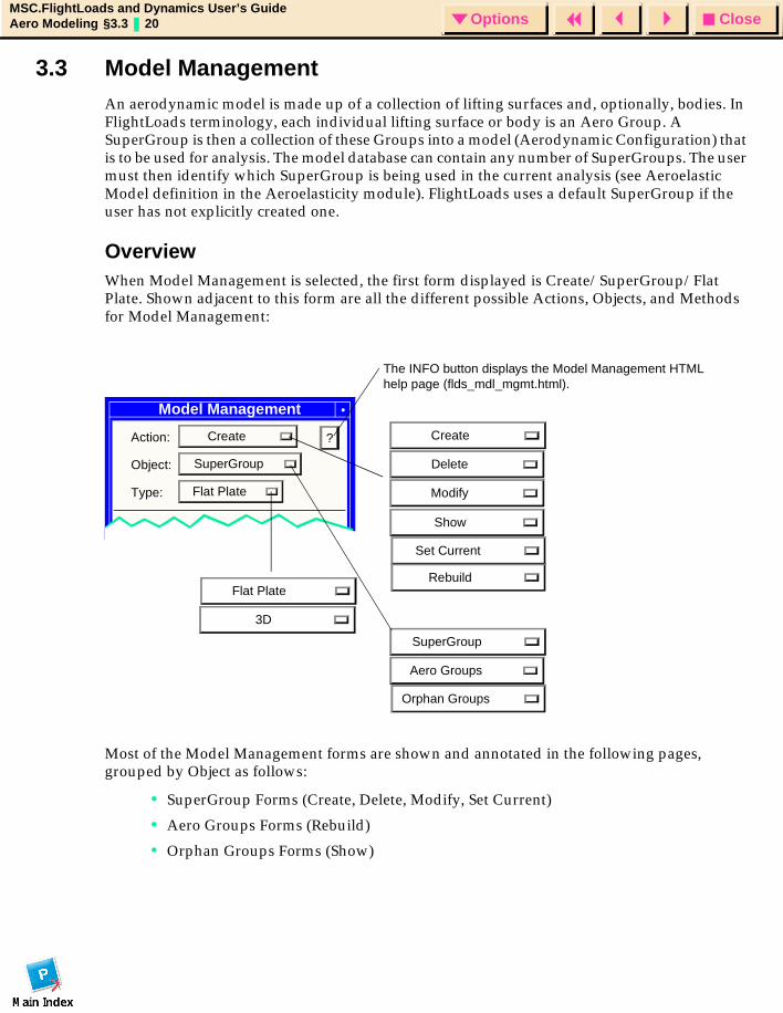
3.3 Model Management An aerodynamic model is made up of a collection of lifting surfaces and, optionally, bodies. In FlightLoads terminology, each individual lifting surface or body is an Aero Group. A SuperGroup is then a collection of these Groups into a model (Aerodynamic Configuration) that is to be used for analysis. The model database can contain any number of SuperGroups. The user must then identify which SuperGroup is being used in the current analysis (see Aeroelastic Model definition in the Aeroelasticity module). FlightLoads uses a default SuperGroup if the user has not explicitly created one.
OverviewWhen Model Management is selected, the first form displayed is Create/SuperGroup/Flat Plate. Shown adjacent to this form are all the different possible Actions, Objects, and Methods for Model Management:
Most of the Model Management forms are shown and annotated in the following pages, grouped by Object as follows:
• SuperGroup Forms (Create, Delete, Modify, Set Current)
• Aero Groups Forms (Rebuild)
• Orphan Groups Forms (Show)
Create
Delete
Modify
Show
Set Current
RebuildFlat Plate
SuperGroup
Aero Groups
Orphan Groups
Model Management
Action: Create
Object: SuperGroup
Type: Flat Plate
?
The INFO button displays the Model Management HTML help page (flds_mdl_mgmt.html).
3D
CloseOptionsMSC.FlightLoads and Dynamics User’s GuideAero Modeling §3.3 21 Options
Definitions for the Model Management Objects
A SuperGroup is the name of an aerodynamic model which is a collection of Aero Groups. Any number of SuperGroups can be defined in a single database. Aero Groups cannot be shared by SuperGroups. A SuperGroup name is limited to 8 characters; this name is used to qualify model data, by configuration, on an MSC.Nastran Aerodynamic or Aeroelastic Database and corresponds to the “AECONFIG” Case Control name in MSC.Nastran subcases.
Aero Groups are individual aerodynamic surface or body macroelements. (In MSC.Nastran terminology, these are CAERO1 or CAERO2 bulk data entries.)
Orphan Groups are Aero Groups that are not assigned to any SuperGroup. This can happen, for example, if a SuperGroup is deleted.
CloseOptionsMSC.FlightLoads and Dynamics User’s GuideAero Modeling §3.3 22 Options
Model Management FormsThis subsection provides annotated illustrations for the Model Management forms. Note that the Type for all of these forms is Flat Plate which refers to the Doublet Lattice/ZONA51 aerodynamic modeling methods that are characterized as being 2D panel methods (flat surfaces in 3D-space) as opposed to 3D methods (general surfaces in 3-space). The 3D version of the form is exactly the same as the Flat Plate versions shown on the next few pages. The available set of forms are:
SuperGroup Forms:
• Create/SuperGroup
• Delete/SuperGroup
• Modify/SuperGroup
• Show/SuperGroup
• Set Current/SuperGroup
Aero Groups Forms:
• Rebuild/Aero Groups
Orphan Groups Forms:
• Show/Orphan Groups
CloseOptionsMSC.FlightLoads and Dynamics User’s GuideAero Modeling §3.3 23 Options
SuperGroup Forms
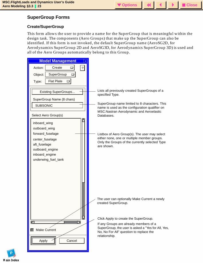
Create/SuperGroup
This form allows the user to provide a name for the SuperGroup that is meaningful within the design task. The components (Aero Groups) that make up the SuperGroup can also be identified. If this form is not invoked, the default SuperGroup name (AeroSG2D, for Aerodynamics SuperGroup 2D and AeroSG3D, for Aerodynamics SuperGroup 3D) is used and all of the Aero Groups automatically belong to this Group.
Model Management
Action: Create
Object: SuperGroup
Type: Flat Plate
Existing SuperGroups...
SuperGroup Name (8 chars)
Select Aero Group(s)
Make Current
Apply Cancel
?
SUBSONIC
center_fuselage
aft_fuselage
outboard_engine
inboard_engine
underwing_fuel_tank
Lists all previously created SuperGroups of a specified Type.
SuperGroup name limited to 8 characters. This name is used as the configuration qualifier on MSC.Nastran Aerodynamic and Aeroelastic Databases.
Listbox of Aero Group(s). The user may select either none, one or multiple member groups. Only the Groups of the currently selected Type are shown.
Click Apply to create the SuperGroup.
If any Groups are already members of a SuperGroup, the user is asked a "Yes for All, Yes, No, No For All" question to replace the relationship.
The user can optionally Make Current a newly created SuperGroup.
forward_fuselage
outboard_wing
inboard_wing

CloseOptionsMSC.FlightLoads and Dynamics User’s GuideAero Modeling §3.3 24 Options
Delete/SuperGroup
This form (not shown) deletes the selected SuperGroup(s). The associated Aero Groups are not deleted but become "Orphan". The current SuperGroup does not appear within the Select SuperGroup(s) box and cannot be deleted.
Note: Only SuperGroups of the given type are displayed within the select SuperGroup(s) box.
CloseOptionsMSC.FlightLoads and Dynamics User’s GuideAero Modeling §3.3 25 Options
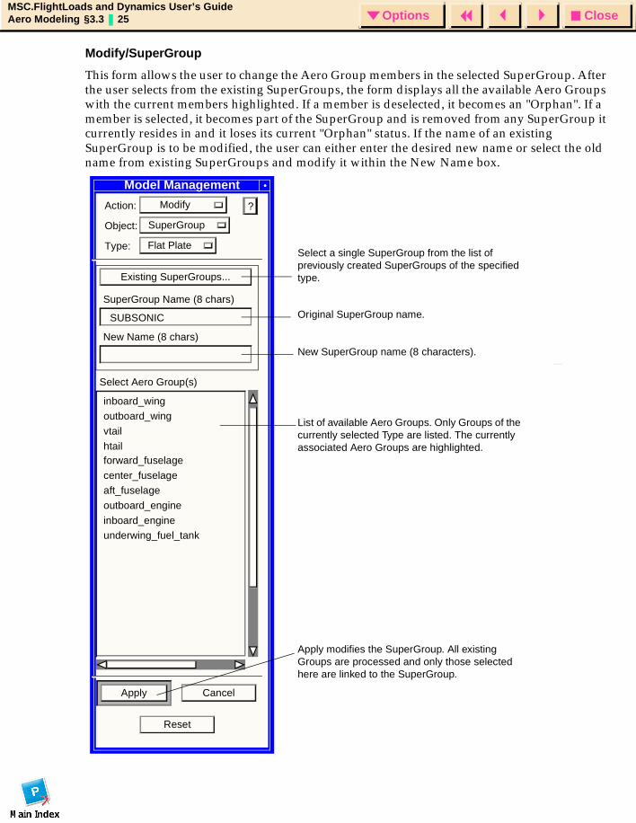
Modify/SuperGroup
This form allows the user to change the Aero Group members in the selected SuperGroup. After the user selects from the existing SuperGroups, the form displays all the available Aero Groups with the current members highlighted. If a member is deselected, it becomes an "Orphan". If a member is selected, it becomes part of the SuperGroup and is removed from any SuperGroup it currently resides in and it loses its current "Orphan" status. If the name of an existing SuperGroup is to be modified, the user can either enter the desired new name or select the old name from existing SuperGroups and modify it within the New Name box.
Model Management
Action: Modify
Object: SuperGroup
Type: Flat Plate
Existing SuperGroups...
SuperGroup Name (8 chars)
Select Aero Group(s)
Apply Cancel
?
SUBSONIC
forward_fuselage
center_fuselageaft_fuselage
outboard_engine
inboard_engineunderwing_fuel_tank
Reset
New Name (8 chars)
Select a single SuperGroup from the list of previously created SuperGroups of the specified type.
Original SuperGroup name.
New SuperGroup name (8 characters).
List of available Aero Groups. Only Groups of the currently selected Type are listed. The currently associated Aero Groups are highlighted.
Apply modifies the SuperGroup. All existing Groups are processed and only those selected here are linked to the SuperGroup.
inboard_wingoutboard_wing
vtail
htail
CloseOptionsMSC.FlightLoads and Dynamics User’s GuideAero Modeling §3.3 26 Options
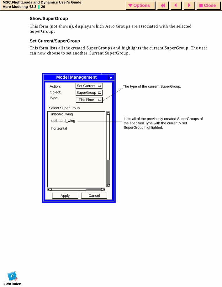
Show/SuperGroup
This form (not shown), displays which Aero Groups are associated with the selected SuperGroup.
Set Current/SuperGroup
This form lists all the created SuperGroups and highlights the current SuperGroup. The user can now choose to set another Current SuperGroup.
Lists all of the previously created SuperGroups of the specified Type with the currently set SuperGroup highlighted.
Set Current
Apply Cancel
Select SuperGroup
Model Management
Action:
Object:
Type:
inboard_wing
outboard_wing
horizontal
SuperGroup
Flat Plate
The type of the current SuperGroup.
CloseOptionsMSC.FlightLoads and Dynamics User’s GuideAero Modeling §3.3 27 Options
Aero Groups Forms
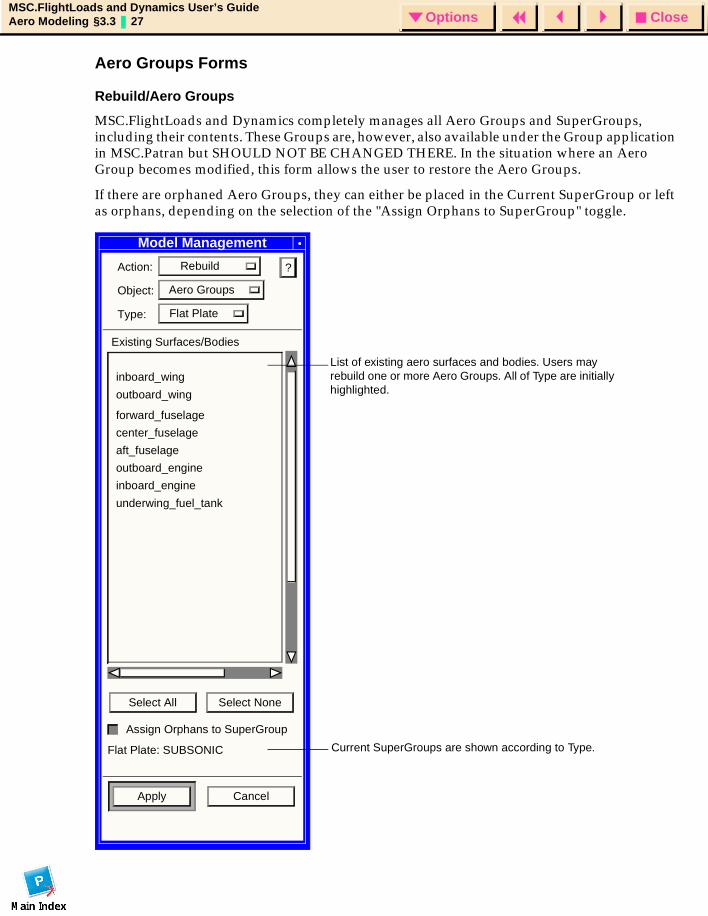
Rebuild/Aero Groups
MSC.FlightLoads and Dynamics completely manages all Aero Groups and SuperGroups, including their contents. These Groups are, however, also available under the Group application in MSC.Patran but SHOULD NOT BE CHANGED THERE. In the situation where an Aero Group becomes modified, this form allows the user to restore the Aero Groups.
If there are orphaned Aero Groups, they can either be placed in the Current SuperGroup or left as orphans, depending on the selection of the "Assign Orphans to SuperGroup" toggle.
Model Management
Action: Rebuild
Object: Aero Groups
Type: Flat Plate
Existing Surfaces/Bodies
Apply Cancel
?
forward_fuselage
center_fuselage
aft_fuselage
outboard_engine
inboard_engine
underwing_fuel_tank
Select All Select None
Assign Orphans to SuperGroup
Flat Plate: SUBSONIC
List of existing aero surfaces and bodies. Users may rebuild one or more Aero Groups. All of Type are initially highlighted.
Current SuperGroups are shown according to Type.
inboard_wing
outboard_wing
CloseOptionsMSC.FlightLoads and Dynamics User’s GuideAero Modeling §3.3 28 Options
Orphan Groups Forms
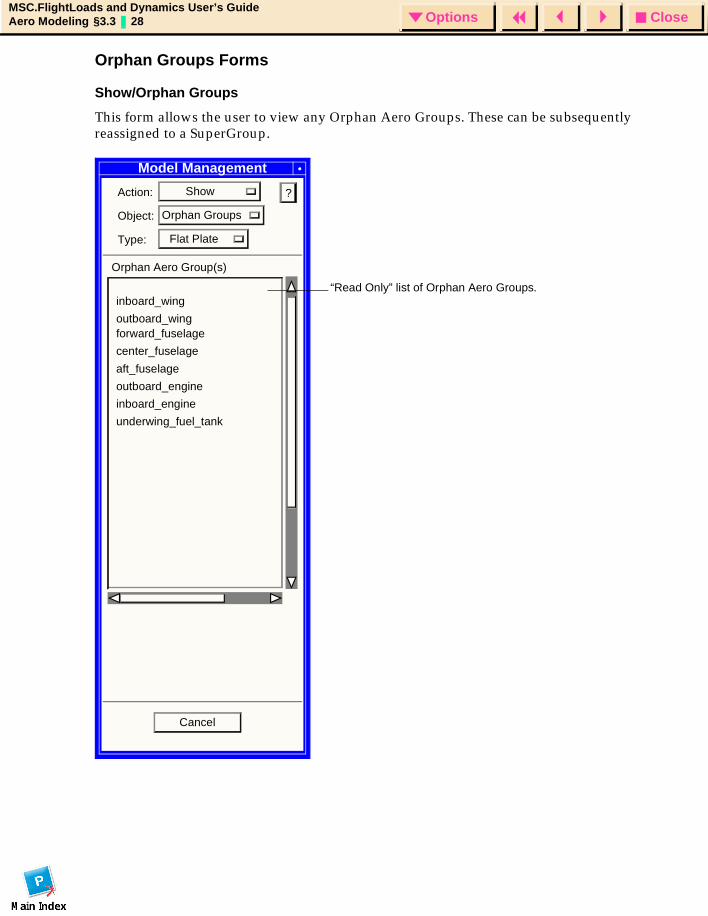
Show/Orphan Groups
This form allows the user to view any Orphan Aero Groups. These can be subsequently reassigned to a SuperGroup.
Model Management
Action: Show
Object: Orphan Groups
Type: Flat Plate
Orphan Aero Group(s)
Cancel
?
forward_fuselage
center_fuselage
aft_fuselage
outboard_engine
inboard_engine
underwing_fuel_tank
“Read Only” list of Orphan Aero Groups.inboard_wing
outboard_wing
CloseOptionsMSC.FlightLoads and Dynamics User’s GuideAero Modeling §3.4 29 Options
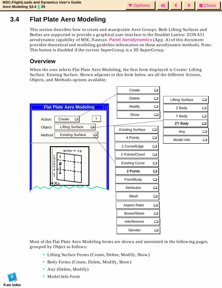
3.4 Flat Plate Aero Modeling This section describes how to create and manipulate Aero Groups. Both Lifting Surfaces and Bodies are supported to provide a graphical user interface to the Doublet Lattice/ZONA51 aerodynamic capability of MSC.Nastran. Panel Aerodynamics (App. A) of this document provides theoretical and modeling guideline information on these aerodynamic methods. Note: This button is disabled if the current SuperGroup is a 3D SuperGroup.
OverviewWhen the user selects Flat Plate Aero Modeling, the first form displayed is Create/Lifting Surface/Existing Surface. Shown adjacent to this form below are all the different Actions, Objects, and Methods options available:
Most of the Flat Plate Aero Modeling forms are shown and annotated in the following pages, grouped by Object as follows:
• Lifting Surface Forms (Create, Delete, Modify, Show)
• Body Forms (Create, Delete, Modify, Show)
• Any (Delete, Modify)
• Model Info Form
Flat Plate Aero Modeling
Action: Create
Object: Lifting Surface
Method Existing Surface
?
Create
Delete
Modify
Show
2 Curve/Edge
Existing Surface
4 Points
2 Points/Chord
Existing Curve
2 Points
Point/Body
Attributes
Mesh
Aspect Ratio
Boxes/Wave
Interference
Slender
2 Points
Lifting Surface
Z Body
Y Body
ZY BodyZY Body
Model Info
Any
CloseOptionsMSC.FlightLoads and Dynamics User’s GuideAero Modeling §3.4 30 Options
Definitions for the Flat Plate Aero Modeling Objects
A Lifting Surface is the representation of a winglike surface that provides the primary lifting capability for the wing surface. Both the Doublet Lattice Method (subsonic) and ZONA51 (supersonic) aerodynamic codes support lifting surfaces modeled as a trapezoid with inboard and outboard edges that are parallel to the direction of the flow (the X-coordinate of the aerodynamic coordinate system).
The Doublet Lattice Method (but not ZONA51) also supports the ability to model bodies, such as fuselages, external fuel tanks and other ‘‘stores’’ and/or engine nacelles. The theory requires the user to distinguish the bodies based on the types of motion they can sustain. A Z Body can only move in the Z-direction of the aerodynamic coordinate system. A Y Body can only move in the Y-direction of the aerodynamic coordinate system.
A ZY Body can move in the Z and Y directions. This option would typically be selected in an asymmetric analysis and for bodies that are not on the plane of symmetry (such as engine nacelles).
Flat Plate Aero Modeling Forms
This subsection provides annotated illustrations for the Flat Plate Aero Modeling forms. The available set of forms are:
Lifting Surface FormsCreate Forms
• Create/Lifting Surface/Existing Surface
• Create/Lifting Surface/4 Points
• Create/Lifting Surface/2 Curve/Edge
• Create/Lifting Surface/2 Points/Chord
• Create/Lifting Surface Subforms
• Existing Surfaces
• Mesh Control
• Optional Data
Delete Forms
• Delete/Lifting Surface
Modify Forms
• Modify/Lifting Surface
Show Forms
• Show/Lifting Surface /Attributes
• Show/Lifting Surface /Mesh
• Show/Lifting Surface /Aspect Ratio
• Show/Lifting Surface/Boxes/Wave
• Non-Dimensional Option
• Show/Lifting Surface Subforms
CloseOptionsMSC.FlightLoads and Dynamics User’s GuideAero Modeling §3.4 31 Options
• Fringe Attribute
Body FormsZ Body, Y Body, and ZY Body Forms
• Create/Body/Existing Curve
• Create/Body/2 Points
• Create/Body/Point/Body
• Create/Body Subforms
• Existing Bodies
• Mesh Control
• Additional Body Data
• Modify/Body
• Mesh Control
• Delete/Body
• Show/Body/Attributes
• Show/Body/Mesh
• Show/Body/Interference
• Show/Body/Slender
• Delete/Any
• Modify/Any
• Show Model Information
• Show/All Model Information
CloseOptionsMSC.FlightLoads and Dynamics User’s GuideAero Modeling §3.4 32 Options
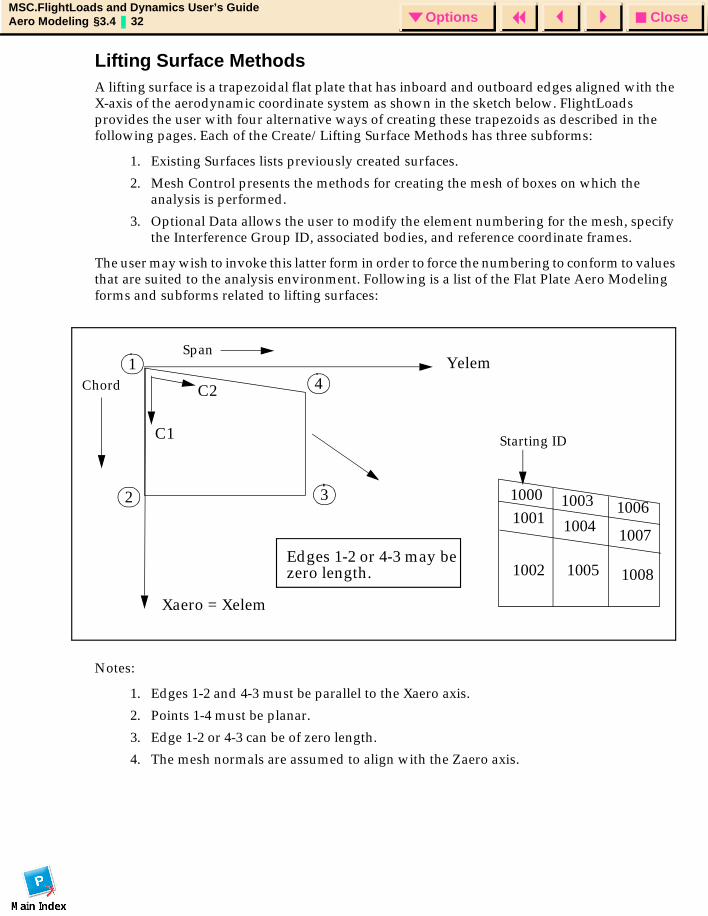
Lifting Surface MethodsA lifting surface is a trapezoidal flat plate that has inboard and outboard edges aligned with the X-axis of the aerodynamic coordinate system as shown in the sketch below. FlightLoads provides the user with four alternative ways of creating these trapezoids as described in the following pages. Each of the Create/Lifting Surface Methods has three subforms:
1. Existing Surfaces lists previously created surfaces.
2. Mesh Control presents the methods for creating the mesh of boxes on which the analysis is performed.
3. Optional Data allows the user to modify the element numbering for the mesh, specify the Interference Group ID, associated bodies, and reference coordinate frames.
The user may wish to invoke this latter form in order to force the numbering to conform to values that are suited to the analysis environment. Following is a list of the Flat Plate Aero Modeling forms and subforms related to lifting surfaces:
Notes:
1. Edges 1-2 and 4-3 must be parallel to the Xaero axis.
2. Points 1-4 must be planar.
3. Edge 1-2 or 4-3 can be of zero length.
4. The mesh normals are assumed to align with the Zaero axis.
Xaero = Xelem
Yelem
C1
C2
1
2 3
4
10001001
1002
1003
1004
1005
1006
1007
1008
Starting ID
Chord
Span
Edges 1-2 or 4-3 may bezero length.
CloseOptionsMSC.FlightLoads and Dynamics User’s GuideAero Modeling §3.4 33 Options
Lifting Surface Forms
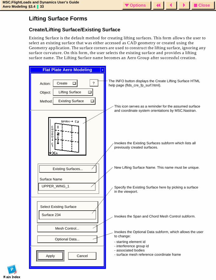
Create/Lifting Surface/Existing Surface
Existing Surface is the default method for creating lifting surfaces. This form allows the user to select an existing surface that was either accessed as CAD geometry or created using the Geometry application. The surface corners are used to construct the lifting surface, ignoring any surface curvature. On this form, the user selects the existing surface and provides a lifting surface name. The Lifting Surface name becomes an Aero Group after successful creation.
Flat Plate Aero Modeling
Action: Create
Object: Lifting Surface
Method: Existing Surface
Existing Surfaces...
Surface Name
Select Existing Surface
Mesh Control...
Optional Data...
Apply Cancel
?
UPPER_WING_1
Surface 234
This icon serves as a reminder for the assumed surface and coordinate system orientations by MSC.Nastran.
Invokes the Existing Surfaces subform which lists all previously created surfaces.
New Lifting Surface Name. This name must be unique.
Specify the Existing Surface here by picking a surface in the viewport.
Invokes the Span and Chord Mesh Control subform.
Invokes the Optional Data subform, which allows the user to change:
- starting element id- interference group id- associated bodies- surface mesh reference coordinate frame
The INFO button displays the Create Lifting Surface HTML help page (flds_cre_fp_surf.html).
CloseOptionsMSC.FlightLoads and Dynamics User’s GuideAero Modeling §3.4 34 Options
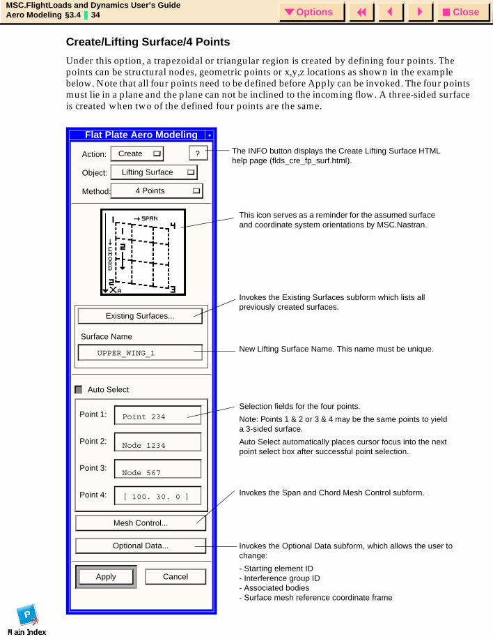
Create/Lifting Surface/4 Points
Under this option, a trapezoidal or triangular region is created by defining four points. The points can be structural nodes, geometric points or x,y,z locations as shown in the example below. Note that all four points need to be defined before Apply can be invoked. The four points must lie in a plane and the plane can not be inclined to the incoming flow. A three-sided surface is created when two of the defined four points are the same.
Flat Plate Aero Modeling
Action: Create
Object: Lifting Surface
Method: 4 Points
Existing Surfaces...
Surface Name
Auto Select
Point 1:
Point 2:
Point 3:
Point 4:
Mesh Control...
Optional Data...
Apply Cancel
?
UPPER_WING_1
Point 234
Node 1234
Node 567
[ 100. 30. 0 ]
This icon serves as a reminder for the assumed surface and coordinate system orientations by MSC.Nastran.
Invokes the Existing Surfaces subform which lists all previously created surfaces.
New Lifting Surface Name. This name must be unique.
Selection fields for the four points.
Note: Points 1 & 2 or 3 & 4 may be the same points to yield a 3-sided surface.
Auto Select automatically places cursor focus into the next point select box after successful point selection.
Invokes the Span and Chord Mesh Control subform.
Invokes the Optional Data subform, which allows the user to change:
- Starting element ID- Interference group ID- Associated bodies - Surface mesh reference coordinate frame
The INFO button displays the Create Lifting Surface HTML help page (flds_cre_fp_surf.html).
CloseOptionsMSC.FlightLoads and Dynamics User’s GuideAero Modeling §3.4 35 Options
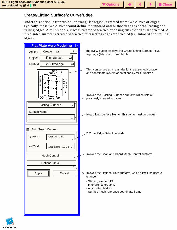
Create/Lifting Surface/2 Curve/Edge
Under this option, a trapezoidal or triangular region is created from two curves or edges. Typically, these two curves would define the inboard and outboard edges or the leading and trailing edges. A four-sided surface is created when two opposing curves/edges are selected. A three-sided surface is created when two intersecting edges are selected (i.e., inboard and trailing edges).
Flat Plate Aero Modeling
Action: Create
Object: Lifting Surface
Method: 2 Curve/Edge
Existing Surfaces...
Surface Name
Auto Select Curves
Curve 1:
Curve 2:
Mesh Control...
Optional Data...
Apply Cancel
?
Curve 234
Surface 1234.2
This icon serves as a reminder for the assumed surface and coordinate system orientations by MSC.Nastran.
Invokes the Existing Surfaces subform which lists all previously created surfaces.
New Lifting Surface Name. This name must be unique.
2 Curve/Edge Selection fields.
Invokes the Span and Chord Mesh Control subform.
Invokes the Optional Data subform, which allows the user to change:
- Starting element ID- Interference group ID- Associated bodies - Surface mesh reference coordinate frame
The INFO button displays the Create Lifting Surface HTML help page (flds_cre_fp_surf.html).
CloseOptionsMSC.FlightLoads and Dynamics User’s GuideAero Modeling §3.4 36 Options
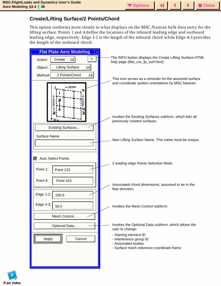
Create/Lifting Surface/2 Points/Chord
This option conforms most closely to what displays on the MSC.Nastran bulk data entry for the lifting surface. Points 1 and 4 define the locations of the inboard leading edge and outboard leading edge, respectively. Edge 1-2 is the length of the inboard chord while Edge 4-3 provides the length of the outboard chord.
Flat Plate Aero Modeling
Action: Create
Object: Lifting Surface
Method: 2 Points/Chord
Existing Surfaces...
Surface Name
Auto Select Points
Point 1:
Point 4:
Edge 1-2:
Edge 4-3:
Mesh Control...
Optional Data...
Apply Cancel
?
This icon serves as a reminder for the assumed surface and coordinate system orientations by MSC.Nastran.
Invokes the Existing Surfaces subform, which lists all previously created surfaces.
New Lifting Surface Name. This name must be unique.
2 leading edge Points Selection fields.
Invokes the Mesh Control subform.
Invokes the Optional Data subform, which allows the user to change:
- Starting element ID- Interference group ID- Associated bodies - Surface mesh reference coordinate frame
Point 123
Point 423
100.0
50.0
Associated chord dimensions, assumed to be in the flow direction.
The INFO button displays the Create Lifting Surface HTML help page (flds_cre_fp_surf.html).
CloseOptionsMSC.FlightLoads and Dynamics User’s GuideAero Modeling §3.4 37 Options
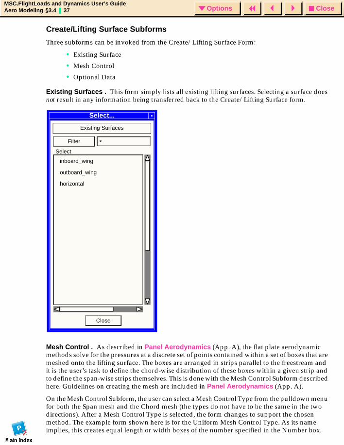
Create/Lifting Surface Subforms
Three subforms can be invoked from the Create/Lifting Surface Form:
• Existing Surface
• Mesh Control
• Optional Data
Existing Surfaces . This form simply lists all existing lifting surfaces. Selecting a surface does not result in any information being transferred back to the Create/Lifting Surface form.
Mesh Control . As described in Panel Aerodynamics (App. A), the flat plate aerodynamic methods solve for the pressures at a discrete set of points contained within a set of boxes that are meshed onto the lifting surface. The boxes are arranged in strips parallel to the freestream and it is the user’s task to define the chord-wise distribution of these boxes within a given strip and to define the span-wise strips themselves. This is done with the Mesh Control Subform described here. Guidelines on creating the mesh are included in Panel Aerodynamics (App. A).
On the Mesh Control Subform, the user can select a Mesh Control Type from the pulldown menu for both the Span mesh and the Chord mesh (the types do not have to be the same in the two directions). After a Mesh Control Type is selected, the form changes to support the chosen method. The example form shown here is for the Uniform Mesh Control Type. As its name implies, this creates equal length or width boxes of the number specified in the Number box.
Select...
Existing Surfaces
inboard_wing
outboard_wing
horizontal
Filter *
Close
Select
CloseOptionsMSC.FlightLoads and Dynamics User’s GuideAero Modeling §3.4 38 Options
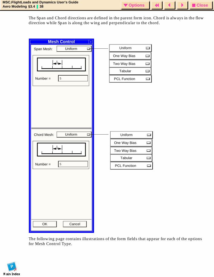
The Span and Chord directions are defined in the parent form icon. Chord is always in the flow direction while Span is along the wing and perpendicular to the chord.
The following page contains illustrations of the form fields that appear for each of the options for Mesh Control Type.
Mesh Control
Span Mesh: Uniform
Number = 5
Chord Mesh: Uniform
Number = 5
OK Cancel
L
PCL Function
Uniform
One Way Bias
Two Way Bias
Tabular
PCL Function
Uniform
One Way Bias
Two Way Bias
Tabular
L
CloseOptionsMSC.FlightLoads and Dynamics User’s GuideAero Modeling §3.4 39 Options
Uniform
This form allows the user to specify an equally distributed mesh along the chosen direction.
One Way Bias
This form allows the user to specify the ratio of the lengths of the first and last boxes and the intermediate boxes are distributed accordingly. This option may be of use in defining the spanwise box distribution since a value less than 1.0 would concentrate boxes at the outboard edge where additional boxes are advised to capture the rapidly changing pressure distribution at the wing tip.
Two Way Bias
This form allows the user to specify the ratio of the middle box to the first and last boxes. Intermediate boxes are distributed accordingly. This option may be of use in defining the chordwise box distribution since a value less than 1.0 would concentrate boxes near the leading and trailing edges, where the pressure gradients are the highest.
Tabular Mesh
This form allows the user to explicitly define the box cut locations. Note that there is one more cut in each direction than there are boxes. The input values are in fractions of chord or span and can therefore range in value from 0.0 to 1.0. It is not necessary that the endpoints be 0.0 or 1.0, although this would be the most typical case. Exceptions are: 1) creating multiple lifting surfaces that represent the same trapezoidal area but specify different ranges for the mesh distribution (so that there is no overlap in meshes) or, 2) the lifting surface may extend to the fuselage centerline, and only the exposed portion of the wing, (that starts at the outer radius of the fuselage), would be meshed.
PCL Function
This option allows the user to select from one of several available options for performing the meshing. Only the listed PCL functions are available. The Cosine distribution is often the ideal selection for the chordwise pattern. Note that this option asks for the number of nodes, which is one more than the number of boxes in the mesh.

CloseOptionsMSC.FlightLoads and Dynamics User’s GuideAero Modeling §3.4 40 Options
Mesh Control Subform (continued)
Chord Mesh: One Way Bias
Number = 5
L2/L1 = 0.2
OK Cancel
L1 L2
Chord Mesh: Two Way Bias
Number = 5
L2/L1 = 0.2
OK Cancel
L1 L2 L1
Chord Mesh: Tabular
Input Data
Clear Sort Reverse
OK Cancel
3
54
21
76
Parametric Value
Chord Mesh: PCL Function
Number of Nodes
5
Select Function
Arc CosineCosineInverse Square RootSquare RootSquared
OK Cancel
The Tabular spreadsheet is initially set to 25 rows. This can be expanded by the user as required, just continue to add data.
The PCL Functions are:
- ArcCosine- Cosine- Inverse Square Root- Square Root- Squared
CloseOptionsMSC.FlightLoads and Dynamics User’s GuideAero Modeling §3.4 41 Options
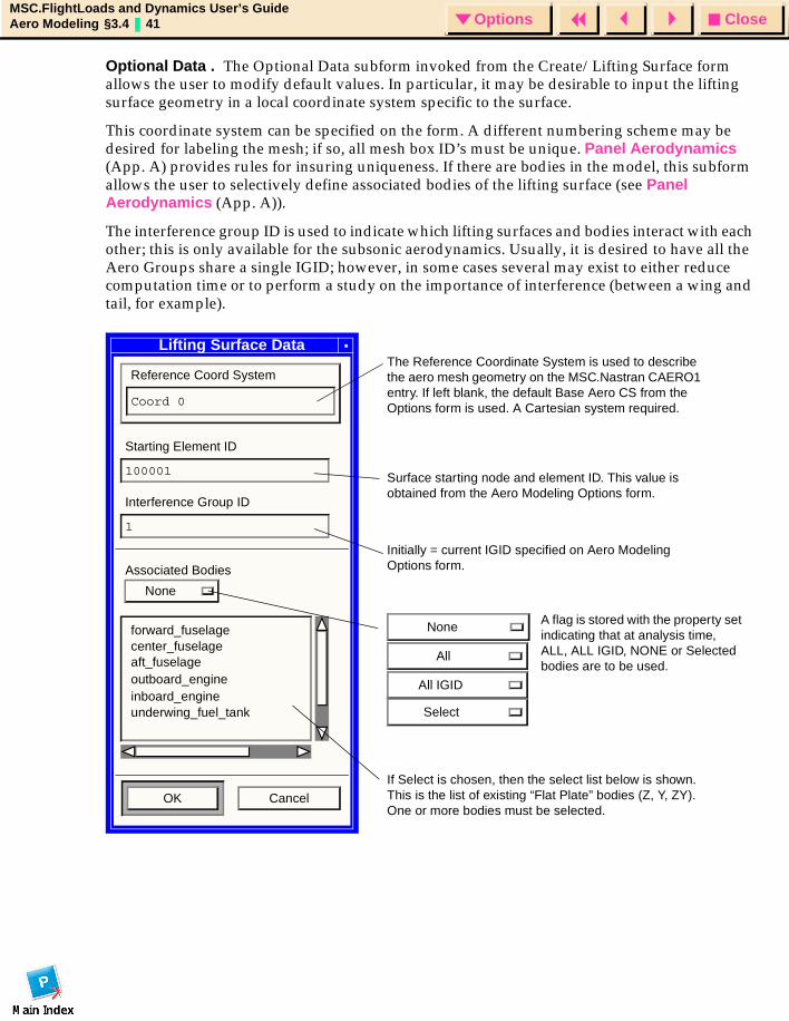
Optional Data . The Optional Data subform invoked from the Create/Lifting Surface form allows the user to modify default values. In particular, it may be desirable to input the lifting surface geometry in a local coordinate system specific to the surface.
This coordinate system can be specified on the form. A different numbering scheme may be desired for labeling the mesh; if so, all mesh box ID’s must be unique. Panel Aerodynamics (App. A) provides rules for insuring uniqueness. If there are bodies in the model, this subform allows the user to selectively define associated bodies of the lifting surface (see Panel Aerodynamics (App. A)).
The interference group ID is used to indicate which lifting surfaces and bodies interact with each other; this is only available for the subsonic aerodynamics. Usually, it is desired to have all the Aero Groups share a single IGID; however, in some cases several may exist to either reduce computation time or to perform a study on the importance of interference (between a wing and tail, for example).
Lifting Surface Data
Reference Coord System
Coord 0
Starting Element ID
100001
Interference Group ID
1
Associated Bodies
None
OK Cancel
forward_fuselagecenter_fuselage aft_fuselageoutboard_engine inboard_engine underwing_fuel_tank
The Reference Coordinate System is used to describe the aero mesh geometry on the MSC.Nastran CAERO1 entry. If left blank, the default Base Aero CS from the Options form is used. A Cartesian system required.
Surface starting node and element ID. This value is obtained from the Aero Modeling Options form.
Initially = current IGID specified on Aero Modeling Options form.
If Select is chosen, then the select list below is shown. This is the list of existing “Flat Plate” bodies (Z, Y, ZY). One or more bodies must be selected.
A flag is stored with the property set indicating that at analysis time, ALL, ALL IGID, NONE or Selected bodies are to be used.
None
All
All IGID
Select
CloseOptionsMSC.FlightLoads and Dynamics User’s GuideAero Modeling §3.4 42 Options
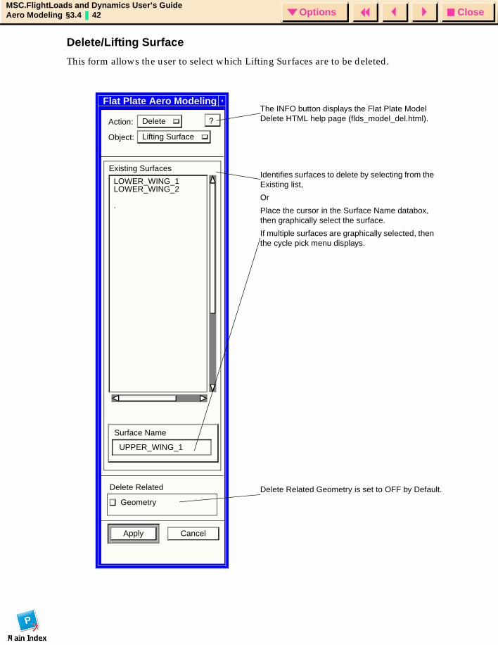
Delete/Lifting Surface
This form allows the user to select which Lifting Surfaces are to be deleted.
Flat Plate Aero Modeling
Action: Delete
Object: Lifting Surface
Existing Surfaces
LOWER_WING_1LOWER_WING_2
Surface Name
UPPER_WING_1
Delete Related
Geometry
Apply Cancel
?
.
Identifies surfaces to delete by selecting from the Existing list,
Or
Place the cursor in the Surface Name databox, then graphically select the surface.
If multiple surfaces are graphically selected, then the cycle pick menu displays.
The INFO button displays the Flat Plate Model Delete HTML help page (flds_model_del.html).
Delete Related Geometry is set to OFF by Default.
CloseOptionsMSC.FlightLoads and Dynamics User’s GuideAero Modeling §3.4 43 Options
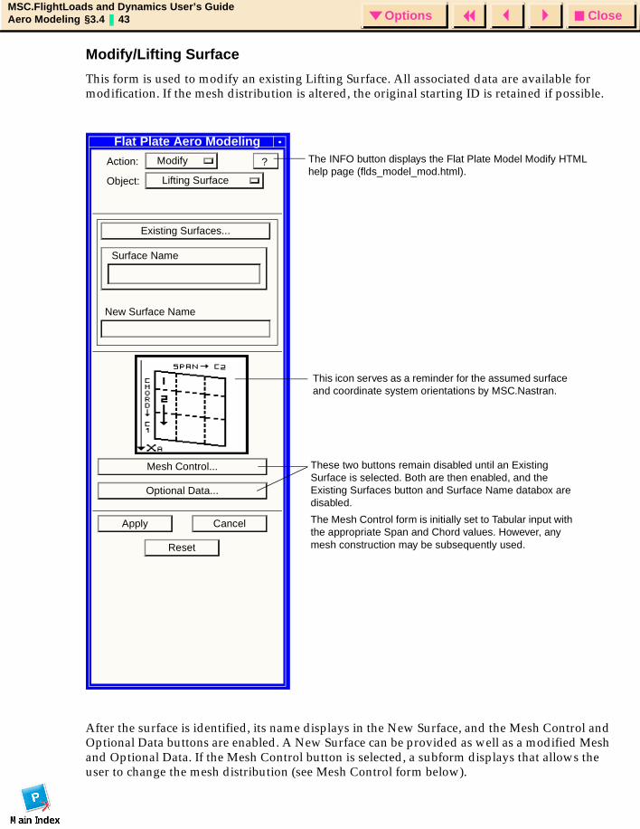
Modify/Lifting Surface
This form is used to modify an existing Lifting Surface. All associated data are available for modification. If the mesh distribution is altered, the original starting ID is retained if possible.
After the surface is identified, its name displays in the New Surface, and the Mesh Control and Optional Data buttons are enabled. A New Surface can be provided as well as a modified Mesh and Optional Data. If the Mesh Control button is selected, a subform displays that allows the user to change the mesh distribution (see Mesh Control form below).
Flat Plate Aero Modeling
Action: Modify
Object: Lifting Surface
Existing Surfaces...
Surface Name
New Surface Name
Mesh Control...
Optional Data...
Apply Cancel
Reset
?
This icon serves as a reminder for the assumed surface and coordinate system orientations by MSC.Nastran.
These two buttons remain disabled until an Existing Surface is selected. Both are then enabled, and the Existing Surfaces button and Surface Name databox are disabled.
The Mesh Control form is initially set to Tabular input with the appropriate Span and Chord values. However, any mesh construction may be subsequently used.
The INFO button displays the Flat Plate Model Modify HTML help page (flds_model_mod.html).
CloseOptionsMSC.FlightLoads and Dynamics User’s GuideAero Modeling §3.4 44 Options
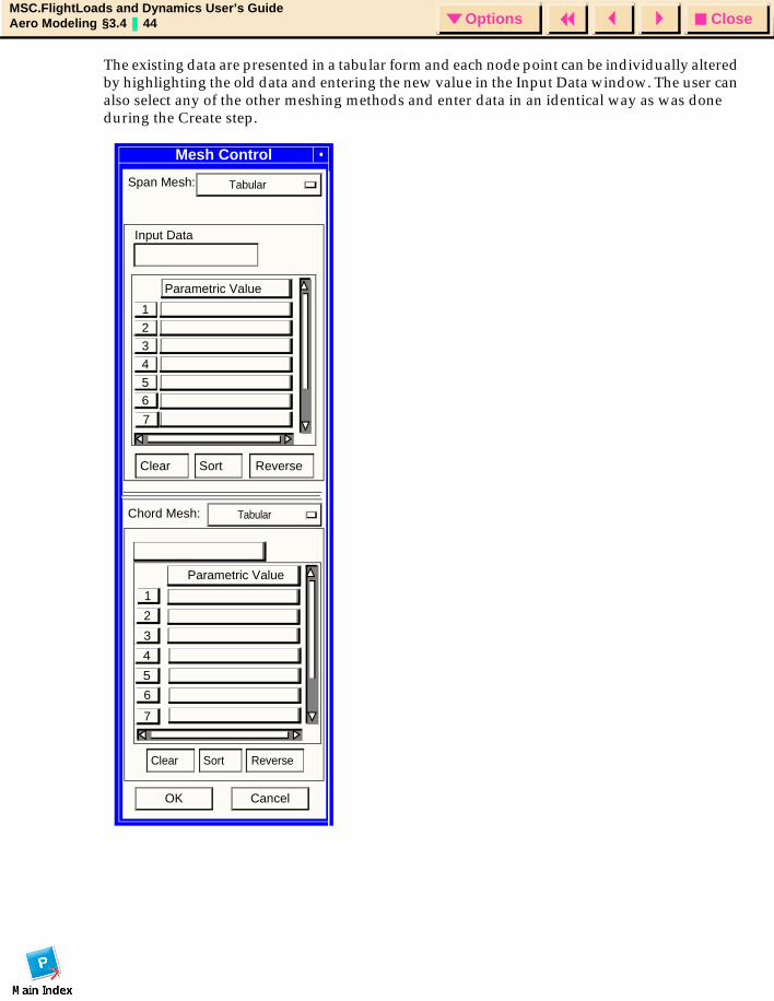
The existing data are presented in a tabular form and each node point can be individually altered by highlighting the old data and entering the new value in the Input Data window. The user can also select any of the other meshing methods and enter data in an identical way as was done during the Create step.
Mesh Control
Span Mesh:
Clear Sort Reverse
3
5
4
2
1
Parametric Value
Input Data
OK Cancel
Mesh Control
Tabular
Clear Sort Reverse
Tabular
6
7
2
3
4
5
7
1
Parametric Value
Chord Mesh:
6
CloseOptionsMSC.FlightLoads and Dynamics User’s GuideAero Modeling §3.4 45 Options
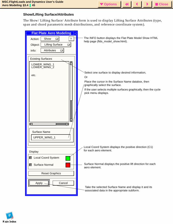
Show/Lifting Surface/Attributes
The Show/Lifting Surface/Attribute form is used to display Lifting Surface Attributes (type, span and chord parametric mesh distributions, and reference coordinate system).
Select one surface to display desired information,
Or
Place the cursor in the Surface Name databox, then graphically select the surface.
If the user selects multiple surfaces graphically, then the cycle pick menu displays.
Flat Plate Aero Modeling
Action: Show
Object: Lifting Surface
Info: Attributes
Existing Surfaces
Surface Name
Display
Local Coord System
Surface Normal
Reset Graphics
Apply Cancel
UPPER_WING_1
LOWER_WING_1LOWER_WING_2
etc.
?
Local Coord System displays the positive direction (C1) for each aero element.
Surface Normal displays the positive lift direction for each aero element.
The INFO button displays the Flat Plate Model Show HTML help page (flds_model_show.html).
Take the selected Surface Name and display it and its associated data in the appropriate subform.
CloseOptionsMSC.FlightLoads and Dynamics User’s GuideAero Modeling §3.4 46 Options
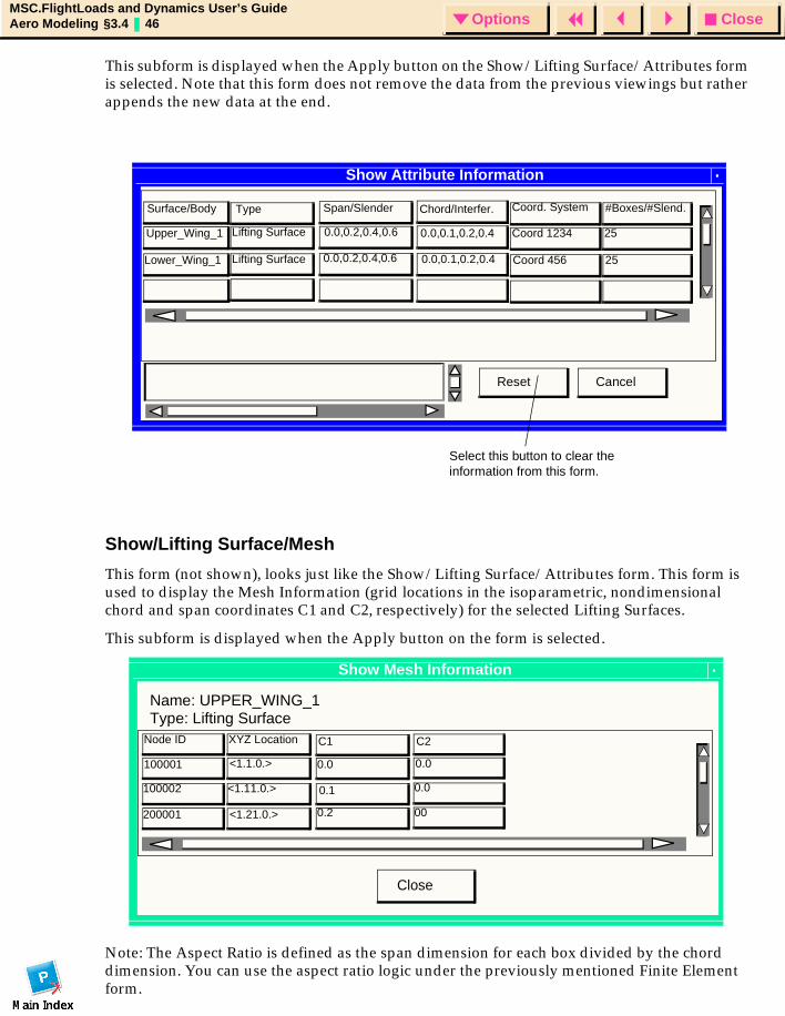
This subform is displayed when the Apply button on the Show/Lifting Surface/Attributes form is selected. Note that this form does not remove the data from the previous viewings but rather appends the new data at the end.
Show/Lifting Surface/Mesh
This form (not shown), looks just like the Show/Lifting Surface/Attributes form. This form is used to display the Mesh Information (grid locations in the isoparametric, nondimensional chord and span coordinates C1 and C2, respectively) for the selected Lifting Surfaces.
This subform is displayed when the Apply button on the form is selected.
Note: The Aspect Ratio is defined as the span dimension for each box divided by the chord dimension. You can use the aspect ratio logic under the previously mentioned Finite Element form.
Show Attribute Information
CancelReset
TypeSurface/Body Span/Slender Chord/Interfer.
0.0,0.1,0.2,0.4
0.0,0.1,0.2,0.4
0.0,0.2,0.4,0.6
0.0,0.2,0.4,0.6
Lifting Surface
Lifting Surface
Upper_Wing_1
Lower_Wing_1
Coord. System
Coord 1234
Coord 456
#Boxes/#Slend.
25
25
Select this button to clear the information from this form.
Show Mesh Information
Name: UPPER_WING_1
Close
Type: Lifting SurfaceNode ID XYZ Location C1 C2
100001 <1.1.0.> 0.0 0.0
0.0
00
0.1
0.2
<1.11.0.>
<1.21.0.>
100002
200001
CloseOptionsMSC.FlightLoads and Dynamics User’s GuideAero Modeling §3.4 47 Options
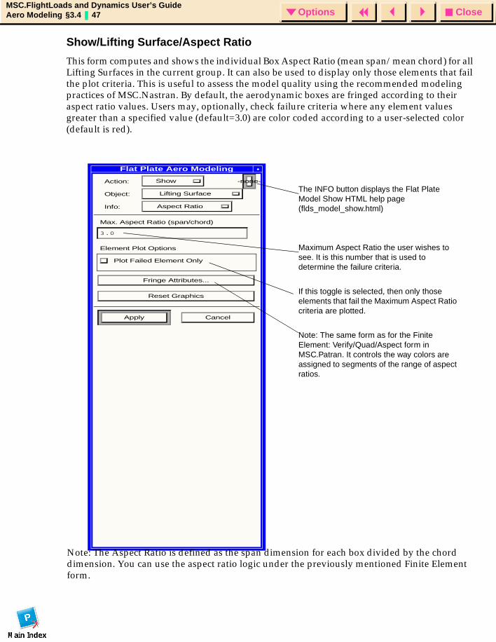
Show/Lifting Surface/Aspect Ratio
This form computes and shows the individual Box Aspect Ratio (mean span/mean chord) for all Lifting Surfaces in the current group. It can also be used to display only those elements that fail the plot criteria. This is useful to assess the model quality using the recommended modeling practices of MSC.Nastran. By default, the aerodynamic boxes are fringed according to their aspect ratio values. Users may, optionally, check failure criteria where any element values greater than a specified value (default=3.0) are color coded according to a user-selected color (default is red).
Flat Plate Aero Modeling
Action: Show -none-
Object: Lifting Surface
Info: Aspect Ratio
Max. Aspect Ratio (span/chord)
3.0
Element Plot Options
Plot Failed Element Only
Fringe Attributes...
Reset Graphics
Apply Cancel
The INFO button displays the Flat Plate Model Show HTML help page (flds_model_show.html)
Maximum Aspect Ratio the user wishes to see. It is this number that is used to determine the failure criteria.
If this toggle is selected, then only those elements that fail the Maximum Aspect Ratio criteria are plotted.
Note: The same form as for the Finite Element: Verify/Quad/Aspect form in MSC.Patran. It controls the way colors are assigned to segments of the range of aspect ratios.
Note: The Aspect Ratio is defined as the span dimension for each box divided by the chord dimension. You can use the aspect ratio logic under the previously mentioned Finite Element form.
CloseOptionsMSC.FlightLoads and Dynamics User’s GuideAero Modeling §3.4 48 Options
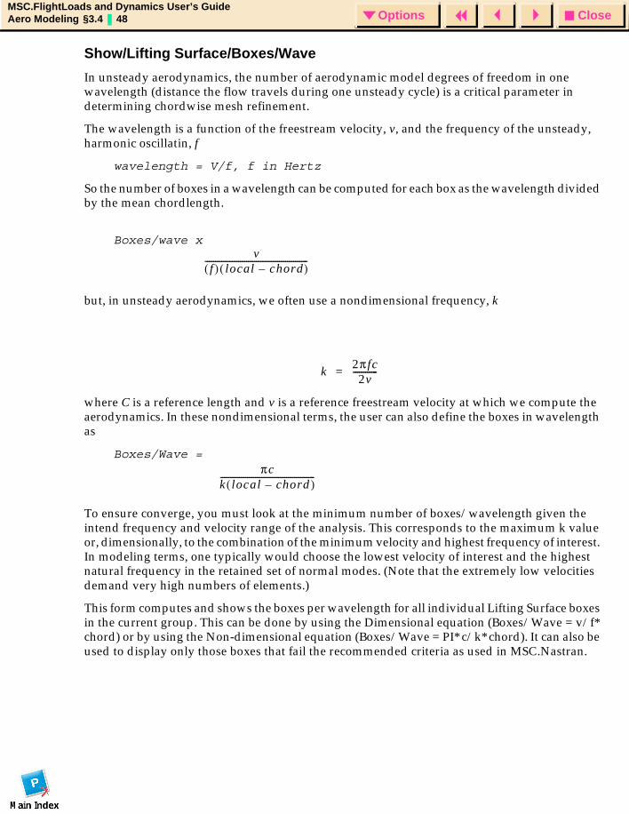
Show/Lifting Surface/Boxes/Wave
In unsteady aerodynamics, the number of aerodynamic model degrees of freedom in one wavelength (distance the flow travels during one unsteady cycle) is a critical parameter in determining chordwise mesh refinement.
The wavelength is a function of the freestream velocity, v, and the frequency of the unsteady, harmonic oscillatin, f
wavelength = V/f, f in Hertz
So the number of boxes in a wavelength can be computed for each box as the wavelength divided by the mean chordlength.
Boxes/wave x
but, in unsteady aerodynamics, we often use a nondimensional frequency, k
where C is a reference length and v is a reference freestream velocity at which we compute the aerodynamics. In these nondimensional terms, the user can also define the boxes in wavelength as
Boxes/Wave =
To ensure converge, you must look at the minimum number of boxes/wavelength given the intend frequency and velocity range of the analysis. This corresponds to the maximum k value or, dimensionally, to the combination of the minimum velocity and highest frequency of interest. In modeling terms, one typically would choose the lowest velocity of interest and the highest natural frequency in the retained set of normal modes. (Note that the extremely low velocities demand very high numbers of elements.)
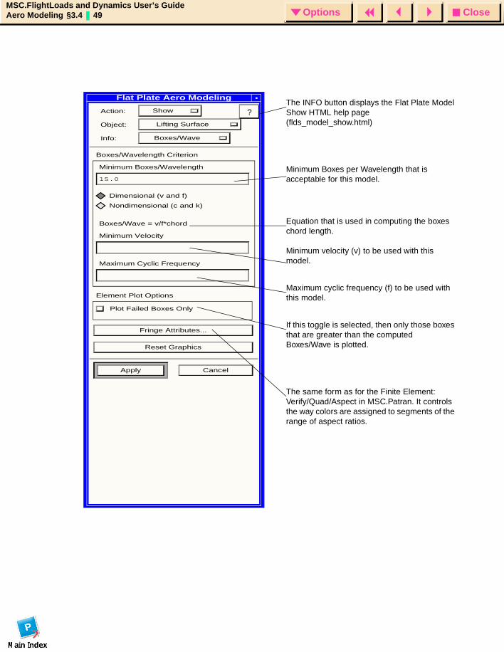
This form computes and shows the boxes per wavelength for all individual Lifting Surface boxes in the current group. This can be done by using the Dimensional equation (Boxes/Wave = v/f* chord) or by using the Non-dimensional equation (Boxes/Wave = PI* c/k* chord). It can also be used to display only those boxes that fail the recommended criteria as used in MSC.Nastran.
vf( ) local chord–( )
--------------------------------------------------
k2π fc
2v------------=
πck local chord–( )----------------------------------------------
CloseOptionsMSC.FlightLoads and Dynamics User’s GuideAero Modeling §3.4 49 Options
Flat Plate Aero Modeling
Action: Show
Object: Lifting Surface
Info: Boxes/Wave
Boxes/Wavelength Criterion
Minimum Boxes/Wavelength
15.0
Dimensional (v and f)
Nondimensional (c and k)
Boxes/Wave = v/f*chord
Minimum Velocity
Maximum Cyclic Frequency
Element Plot Options
Plot Failed Boxes Only
Fringe Attributes...
Reset Graphics
Apply Cancel
The INFO button displays the Flat Plate Model Show HTML help page (flds_model_show.html)
The same form as for the Finite Element: Verify/Quad/Aspect in MSC.Patran. It controls the way colors are assigned to segments of the range of aspect ratios.
Minimum Boxes per Wavelength that is acceptable for this model.
Equation that is used in computing the boxes chord length.
Maximum cyclic frequency (f) to be used with this model.
Minimum velocity (v) to be used with this model.
If this toggle is selected, then only those boxes that are greater than the computed Boxes/Wave is plotted.
?
CloseOptionsMSC.FlightLoads and Dynamics User’s GuideAero Modeling §3.4 50 Options
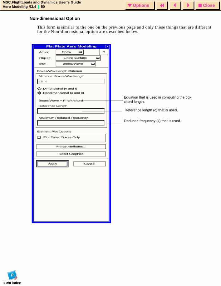
Non-dimensional Option
This form is similar to the one on the previous page and only those things that are different for the Non-dimensional option are described below.
Equation that is used in computing the box chord length.
Reference length (c) that is used.
Reduced frequency (k) that is used.
Flat Plate Aero Modeling
Action: Show
Object: Lifting Surface
Info: Boxes/Wave
Boxes/Wavelength Criterion
Minimum Boxes/Wavelength
15.0
Dimensional (v and f)
Nondimensional (c and k)
Boxes/Wave = PI*c/k*chord
Reference Length
Maximum Reduced Frequency
Element Plot Options
Plot Failed Boxes Only
Fringe Attributes...
Reset Graphics
Apply Cancel
?
CloseOptionsMSC.FlightLoads and Dynamics User’s GuideAero Modeling §3.4 51 Options
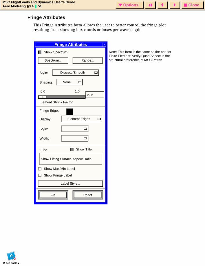
Fringe Attributes
This Fringe Attributes form allows the user to better control the fringe plot resulting from showing box chords or boxes per wavelength.
Note: This form is the same as the one for Finite Element: Verify/Quad/Aspect in the structural preference of MSC.Patran.
Fringe Attributes
Show Spectrum
Spectrum... Range...
Style: Discrete/Smooth
Shading: None
Element Shrink Factor
1.00.00.0
Fringe Edges
Display: Element Edges
Style:
Width:
Show TitleTitle
Show Lifting Surface Aspect Ratio
Show Max/Min Label
Show Fringe Label
Label Style...
OK Reset

CloseOptionsMSC.FlightLoads and Dynamics User’s GuideAero Modeling §3.4 52 Options
Body Forms
Z Body, Y Body and ZY Body
Following is a list of the Flat Plate Aero Modeling forms and subforms related to Z Body, Y Body and ZY Body objects.
All of the forms shown in this section are valid for any of the three Body types; for simplicity, Z Body is shown as the object on all of the forms.
CloseOptionsMSC.FlightLoads and Dynamics User’s GuideAero Modeling §3.4 53 Options
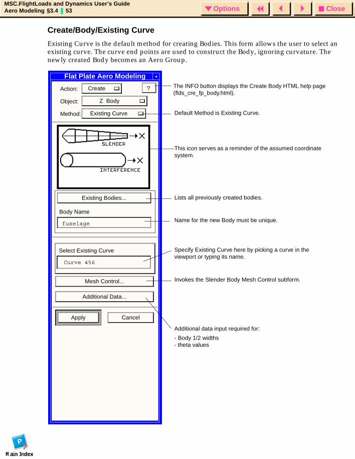
Create/Body/Existing Curve
Existing Curve is the default method for creating Bodies. This form allows the user to select an existing curve. The curve end points are used to construct the Body, ignoring curvature. The newly created Body becomes an Aero Group.
Flat Plate Aero Modeling
Action: Create
Object: Z Body
Method: Existing Curve
Existing Bodies...
Body Name
Select Existing Curve
Mesh Control...
Additional Data...
Apply Cancel
?
Default Method is Existing Curve.
Invokes the Slender Body Mesh Control subform.
This icon serves as a reminder of the assumed coordinate system.
Lists all previously created bodies.
Name for the new Body must be unique.
Specify Existing Curve here by picking a curve in the viewport or typing its name.
Additional data input required for:
- Body 1/2 widths- theta values
fuselage
Curve 456
The INFO button displays the Create Body HTML help page (flds_cre_fp_body.html).
CloseOptionsMSC.FlightLoads and Dynamics User’s GuideAero Modeling §3.4 54 Options
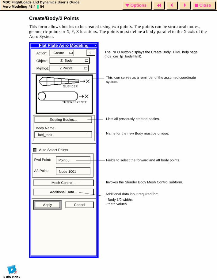
Create/Body/2 Points
This form allows bodies to be created using two points. The points can be structural nodes, geometric points or X, Y, Z locations. The points must define a body parallel to the X-axis of the Aero System.
Flat Plate Aero Modeling
Action: Create
Object: Z Body
Method: 2 Points
Existing Bodies...
Body Name
Auto Select Points
Fwd Point:
Aft Point:
Mesh Control...
Additional Data...
Apply Cancel
?
This icon serves as a reminder of the assumed coordinate system.
Lists all previously created bodies.
Name for the new Body must be unique.
Fields to select the forward and aft body points.
Invokes the Slender Body Mesh Control subform.
Additional data input required for:
- Body 1/2 widths- theta values
fuel_tank
Point 6
Node 1001
The INFO button displays the Create Body HTML help page (flds_cre_fp_body.html).
CloseOptionsMSC.FlightLoads and Dynamics User’s GuideAero Modeling §3.4 55 Options
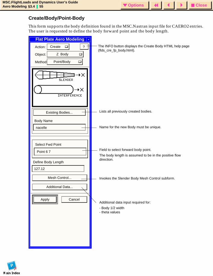
Create/Body/Point-Body
This form supports the body definition found in the MSC.Nastran input file for CAERO2 entries. The user is requested to define the body forward point and the body length.
Flat Plate Aero Modeling
Action: Create
Object: Z Body
Method: Point/Body
Existing Bodies...
Body Name
Select Fwd Point
Define Body Length
Mesh Control...
Additional Data...
Apply Cancel
?
Lists all previously created bodies.
Name for the new Body must be unique.
Field to select forward body point.
The body length is assumed to be in the positive flow direction.
Invokes the Slender Body Mesh Control subform.
Additional data input required for:
- Body 1/2 width- theta values
nacelle
Point 6 7
127.12
The INFO button displays the Create Body HTML help page (flds_cre_fp_body.html).
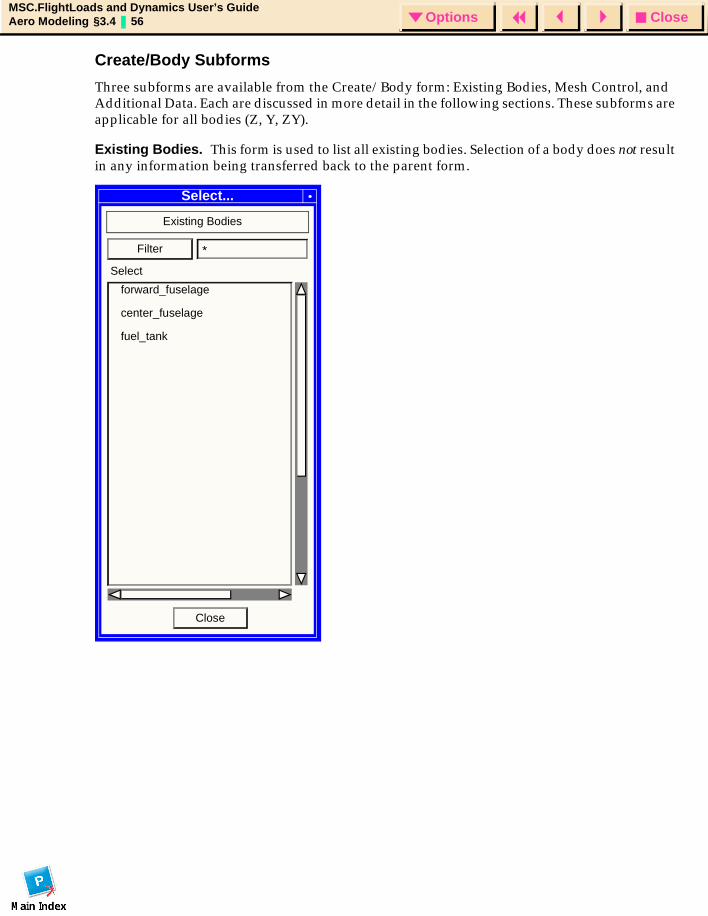
CloseOptionsMSC.FlightLoads and Dynamics User’s GuideAero Modeling §3.4 56 Options
Create/Body Subforms
Three subforms are available from the Create/Body form: Existing Bodies, Mesh Control, and Additional Data. Each are discussed in more detail in the following sections. These subforms are applicable for all bodies (Z, Y, ZY).
Existing Bodies. This form is used to list all existing bodies. Selection of a body does not result in any information being transferred back to the parent form.
Select...
Existing Bodies
forward_fuselage
center_fuselage
fuel_tank
Filter *
Close
Select
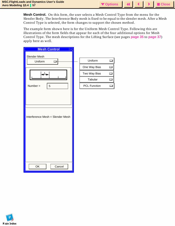
CloseOptionsMSC.FlightLoads and Dynamics User’s GuideAero Modeling §3.4 57 Options
Mesh Control. On this form, the user selects a Mesh Control Type from the menu for the Slender Body. The Interference Body mesh is fixed to be equal to the slender mesh. After a Mesh Control Type is selected, the form changes to support the chosen method.
The example form shown here is for the Uniform Mesh Control Type. Following this are illustrations of the form fields that appear for each of the four additional options for Mesh Control Type. The mesh descriptions for the Lifting Surface (see pages page 35 to page 37) apply here as well.
PCL Function
Uniform
One Way Bias
Two Way Bias
Tabular
Mesh Control
Slender Mesh
Uniform
L
Number = 5
Interference Mesh = Slender Mesh
OK Cancel
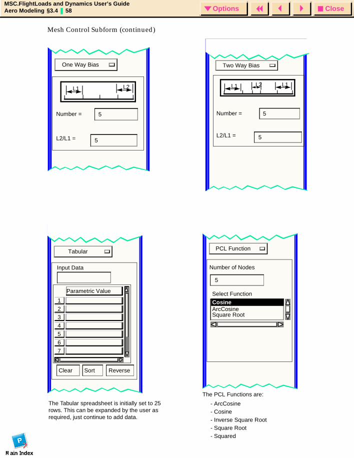
CloseOptionsMSC.FlightLoads and Dynamics User’s GuideAero Modeling §3.4 58 Options
Mesh Control Subform (continued)Mesh Control
One Way Bias
L1 L2
Number = 5
L2/L1 = 5
Mesh Control
Two Way Bias
L1 L2 L1
Mesh Control
Tabular
Clear Sort Reverse
3
5
4
2
1
7
6
Parametric Value
Mesh Control
PCL Function
Number of Nodes
5
Select Function
ArcCosine Square Root
Cosine
Number = 5
L2/L1 = 5
Input Data
The Tabular spreadsheet is initially set to 25 rows. This can be expanded by the user as required, just continue to add data.
The PCL Functions are:
- ArcCosine- Cosine- Inverse Square Root- Square Root- Squared
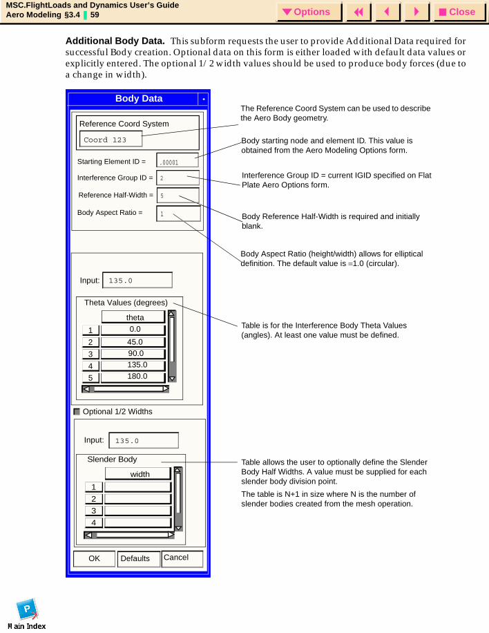
CloseOptionsMSC.FlightLoads and Dynamics User’s GuideAero Modeling §3.4 59 Options
Additional Body Data. This subform requests the user to provide Additional Data required for successful Body creation. Optional data on this form is either loaded with default data values or explicitly entered. The optional 1/2 width values should be used to produce body forces (due to a change in width).
Body Data
Interference Group ID =
Theta Values (degrees)
3
5
4
2
1
theta 0.0
90.0 135.0 180.0
Slender Body
3
4
2
1
width
Reference Coord System
Coord 123
Optional 1/2 Widths
135.0
Input: 135.0
Input:
The Reference Coord System can be used to describe the Aero Body geometry.
Interference Group ID = current IGID specified on Flat Plate Aero Options form.
Body Reference Half-Width is required and initially blank.
Body Aspect Ratio (height/width) allows for elliptical definition. The default value is =1.0 (circular).
Table is for the Interference Body Theta Values (angles). At least one value must be defined.
Table allows the user to optionally define the Slender Body Half Widths. A value must be supplied for each slender body division point.
The table is N+1 in size where N is the number of slender bodies created from the mesh operation.
45.0
.00001
Reference Half-Width =
Body Aspect Ratio =
5
2
OK Defaults Cancel
Starting Element ID =
Body starting node and element ID. This value is obtained from the Aero Modeling Options form.
1
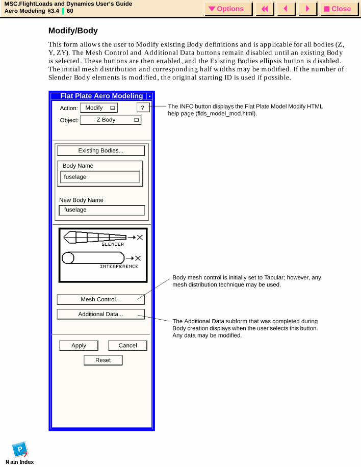
CloseOptionsMSC.FlightLoads and Dynamics User’s GuideAero Modeling §3.4 60 Options
Modify/Body
This form allows the user to Modify existing Body definitions and is applicable for all bodies (Z, Y, ZY). The Mesh Control and Additional Data buttons remain disabled until an existing Body is selected. These buttons are then enabled, and the Existing Bodies ellipsis button is disabled. The initial mesh distribution and corresponding half widths may be modified. If the number of Slender Body elements is modified, the original starting ID is used if possible.
Flat Plate Aero Modeling
Action: Modify
Object: Z Body
Existing Bodies...
Body Name
New Body Name
Mesh Control...
Additional Data...
Apply Cancel
Reset
?
fuselage
fuselage
The Additional Data subform that was completed during Body creation displays when the user selects this button. Any data may be modified.
Body mesh control is initially set to Tabular; however, any mesh distribution technique may be used.
The INFO button displays the Flat Plate Model Modify HTML help page (flds_model_mod.html).
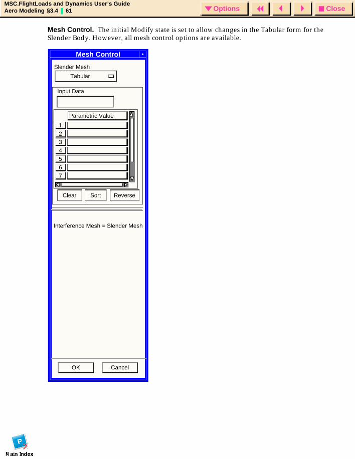
CloseOptionsMSC.FlightLoads and Dynamics User’s GuideAero Modeling §3.4 61 Options
Mesh Control. The initial Modify state is set to allow changes in the Tabular form for the Slender Body. However, all mesh control options are available.
Mesh Control
Slender Mesh
Tabular
Clear Sort Reverse
3
5
4
2
1
76
Parametric Value
Input Data
Interference Mesh = Slender Mesh
OK Cancel
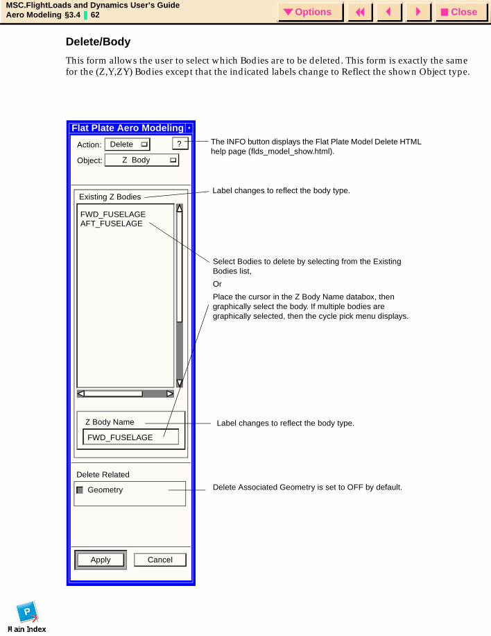
CloseOptionsMSC.FlightLoads and Dynamics User’s GuideAero Modeling §3.4 62 Options
Delete/Body
This form allows the user to select which Bodies are to be deleted. This form is exactly the same for the (Z,Y,ZY) Bodies except that the indicated labels change to Reflect the shown Object type.
Flat Plate Aero Modeling
Action: Delete
Object: Z Body
Existing Z Bodies
Z Body Name
Delete Related
Geometry
Apply Cancel
?
FWD_FUSELAGEAFT_FUSELAGE
FWD_FUSELAGE
Select Bodies to delete by selecting from the Existing Bodies list,
Or
Place the cursor in the Z Body Name databox, then graphically select the body. If multiple bodies are graphically selected, then the cycle pick menu displays.
Delete Associated Geometry is set to OFF by default.
The INFO button displays the Flat Plate Model Delete HTML help page (flds_model_show.html).
Label changes to reflect the body type.
Label changes to reflect the body type.
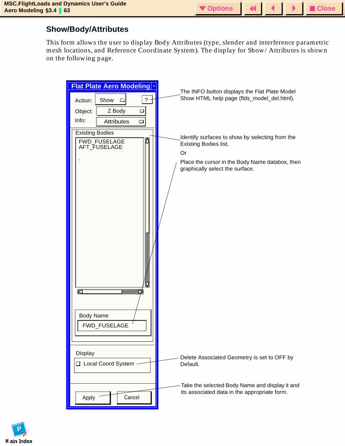
CloseOptionsMSC.FlightLoads and Dynamics User’s GuideAero Modeling §3.4 63 Options
Show/Body/Attributes
This form allows the user to display Body Attributes (type, slender and interference parametric mesh locations, and Reference Coordinate System). The display for Show/Attributes is shown on the following page.
Flat Plate Aero Modeling
Action: Show
Object: Z Body
Existing Bodies
FWD_FUSELAGEAFT_FUSELAGE
Body Name
FWD_FUSELAGE
Display
Local Coord System
?
.
Identify surfaces to show by selecting from the Existing Bodies list,
Or
Place the cursor in the Body Name databox, then graphically select the surface.
The INFO button displays the Flat Plate Model Show HTML help page (flds_model_del.html).
Delete Associated Geometry is set to OFF by Default.
Info:
Apply Cancel
Take the selected Body Name and display it and its associated data in the appropriate form.
Attributes
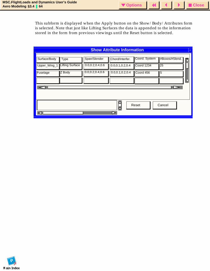
CloseOptionsMSC.FlightLoads and Dynamics User’s GuideAero Modeling §3.4 64 Options
Show Attribute Information
CancelReset
TypeSurface/Body Span/Slender Chord/Interfer.
0.0,0.1,0.2,0.4
0.0,0.1,0.2,0.4
0.0,0.2,0.4,0.6
0.0,0.2,0.4,0.6
Lifting Surface
Z Body
Upper_Wing_1
Fuselage
Coord. System
Coord 1234
Coord 456
#Boxes/#Slend.
25
5
This subform is displayed when the Apply button on the Show/Body/Attributes form is selected. Note that just like Lifting Surfaces the data is appended to the information stored in the form from previous viewings until the Reset button is selected.
Flat Plate Aero Modeling
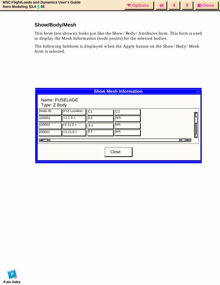
CloseOptionsMSC.FlightLoads and Dynamics User’s GuideAero Modeling §3.4 65 Options
Show Mesh Information
Name: FUSELAGE
Close
Type: Z BodyNode ID XYZ Location C1 C2
100001 <1.1.0.> 0.0 N/A
N/A
N/A
0.1
0.2
<1.11.0.>
<1.21.0.>
100002
200001
Show/Body/Mesh
This form (not shown), looks just like the Show/Body/Attributes form. This form is used to display the Mesh Information (node points) for the selected bodies.
The following Subform is displayed when the Apply button on the Show/Body/Mesh form is selected.
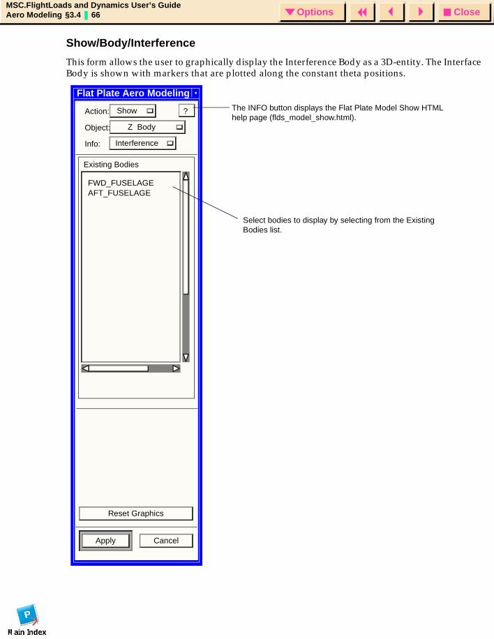
CloseOptionsMSC.FlightLoads and Dynamics User’s GuideAero Modeling §3.4 66 Options
Show/Body/Interference
This form allows the user to graphically display the Interference Body as a 3D-entity. The Interface Body is shown with markers that are plotted along the constant theta positions.
Flat Plate Aero Modeling
Action: Show
Object: Z Body
Info:
Existing Bodies
Reset Graphics
Apply Cancel
?
Select bodies to display by selecting from the Existing Bodies list.
FWD_FUSELAGEAFT_FUSELAGE
The INFO button displays the Flat Plate Model Show HTML help page (flds_model_show.html).
Interference

CloseOptionsMSC.FlightLoads and Dynamics User’s GuideAero Modeling §3.4 67 Options
Show/Body/Slender
This form (not shown), is exactly the same as the Show/Body/Interface form and allows the user to graphically display the Slender Body as a 3D-entity.
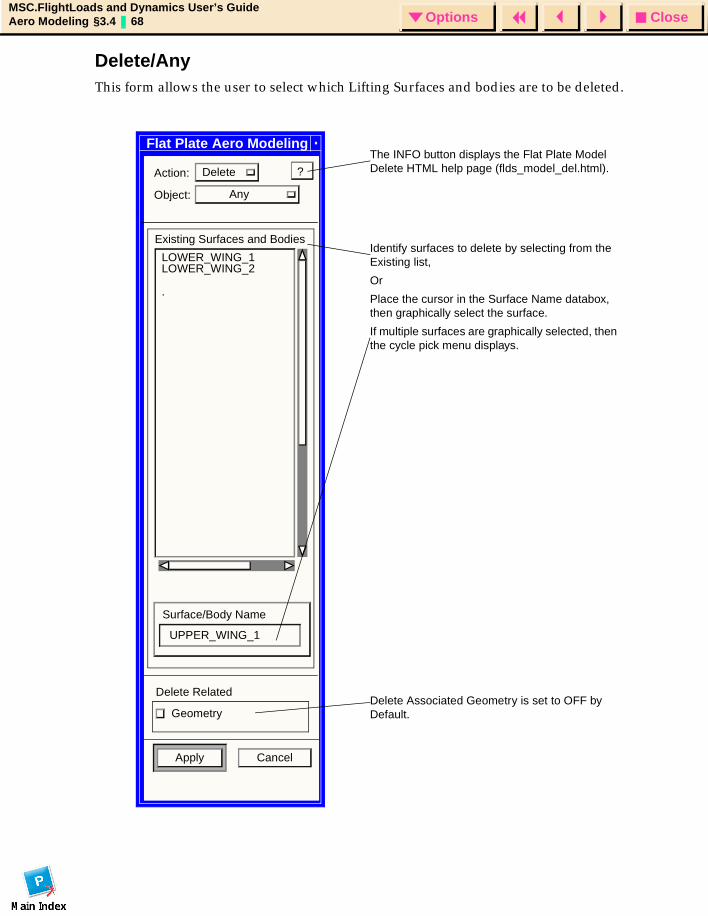
CloseOptionsMSC.FlightLoads and Dynamics User’s GuideAero Modeling §3.4 68 Options
Delete/AnyThis form allows the user to select which Lifting Surfaces and bodies are to be deleted.
Flat Plate Aero Modeling
Action: Delete
Object: Any
Existing Surfaces and Bodies
LOWER_WING_1LOWER_WING_2
Surface/Body Name
UPPER_WING_1
Delete Related
Geometry
Apply Cancel
?
.
Identify surfaces to delete by selecting from the Existing list,
Or
Place the cursor in the Surface Name databox, then graphically select the surface.
If multiple surfaces are graphically selected, then the cycle pick menu displays.
The INFO button displays the Flat Plate Model Delete HTML help page (flds_model_del.html).
Delete Associated Geometry is set to OFF by Default.
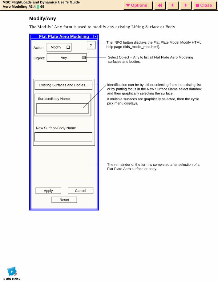
CloseOptionsMSC.FlightLoads and Dynamics User’s GuideAero Modeling §3.4 69 Options
Modify/Any
The Modify/Any form is used to modify any existing Lifting Surface or Body.
Flat Plate Aero Modeling
Action: Modify
Object: Any
Existing Surfaces and Bodies...
Surface/Body Name
New Surface/Body Name
?
Apply Cancel
Reset
Select Object = Any to list all Flat Plate Aero Modeling surfaces and bodies.
Identification can be by either selecting from the existing list or by putting focus in the New Surface Name select databox and then graphically selecting the surface.
If multiple surfaces are graphically selected, then the cycle pick menu displays.
The remainder of the form is completed after selection of a Flat Plate Aero surface or body.
The INFO button displays the Flat Plate Model Modify HTML help page (flds_model_mod.html).
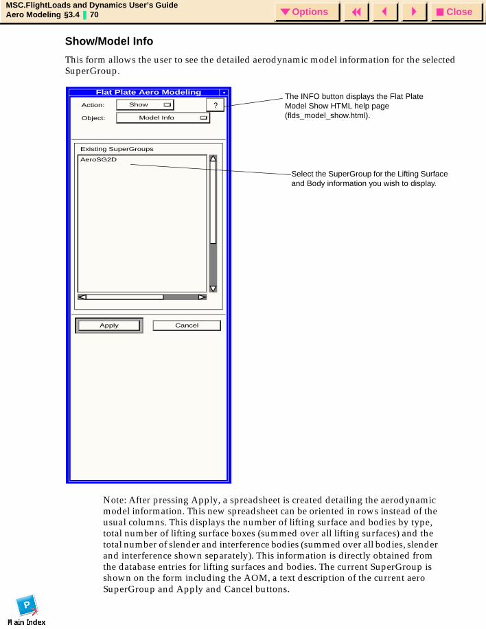
CloseOptionsMSC.FlightLoads and Dynamics User’s GuideAero Modeling §3.4 70 Options
Show/Model Info
This form allows the user to see the detailed aerodynamic model information for the selected SuperGroup.
Flat Plate Aero Modeling
Action: Show
Object: Model Info
Existing SuperGroups
AeroSG2D
Apply Cancel
Select the SuperGroup for the Lifting Surface and Body information you wish to display.
The INFO button displays the Flat Plate Model Show HTML help page (flds_model_show.html).
Note: After pressing Apply, a spreadsheet is created detailing the aerodynamic model information. This new spreadsheet can be oriented in rows instead of the usual columns. This displays the number of lifting surface and bodies by type, total number of lifting surface boxes (summed over all lifting surfaces) and the total number of slender and interference bodies (summed over all bodies, slender and interference shown separately). This information is directly obtained from the database entries for lifting surfaces and bodies. The current SuperGroup is shown on the form including the AOM, a text description of the current aero SuperGroup and Apply and Cancel buttons.
?
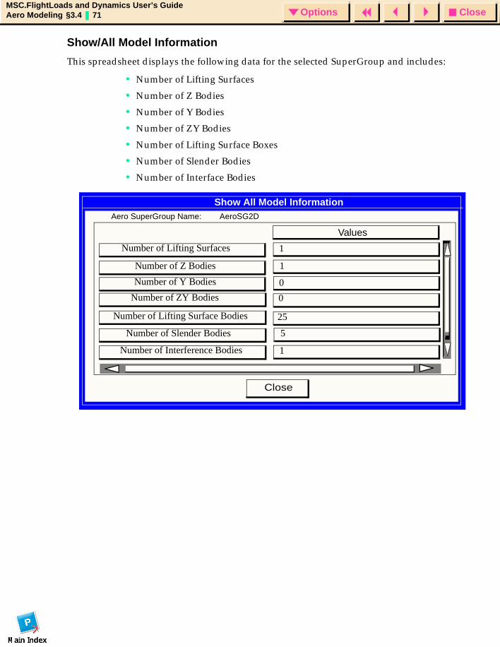
CloseOptionsMSC.FlightLoads and Dynamics User’s GuideAero Modeling §3.4 71 Options
Show/All Model Information
This spreadsheet displays the following data for the selected SuperGroup and includes:
• Number of Lifting Surfaces
• Number of Z Bodies
• Number of Y Bodies
• Number of ZY Bodies
• Number of Lifting Surface Boxes
• Number of Slender Bodies
• Number of Interface Bodies
Close
Show All Model InformationAero SuperGroup Name: AeroSG2D
Values
1
1
0
0
25
5
1
Number of Lifting Surfaces
Number of Z Bodies
Number of Y Bodies
Number of ZY Bodies
Number of Lifting Surface Bodies
Number of Slender Bodies
Number of Interference Bodies
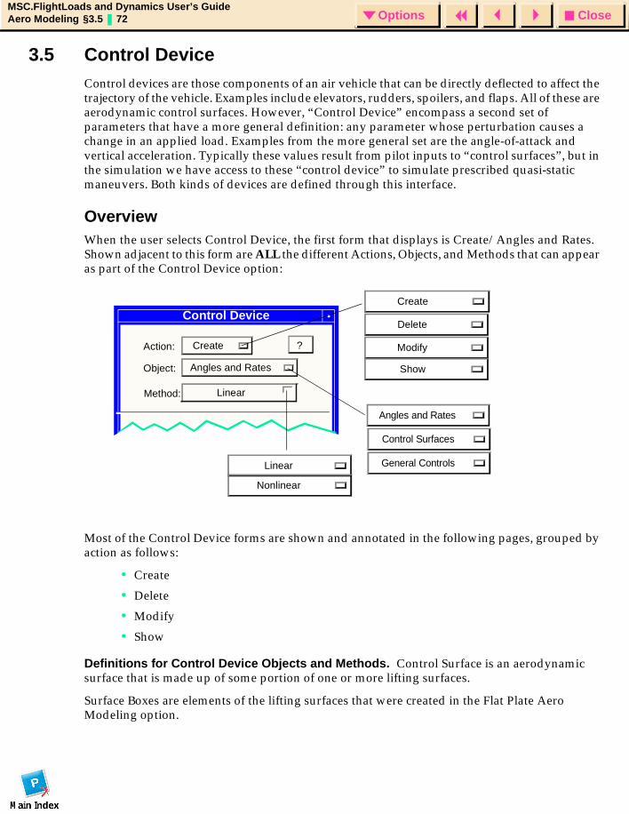
CloseOptionsMSC.FlightLoads and Dynamics User’s GuideAero Modeling §3.5 72 Options
3.5 Control Device Control devices are those components of an air vehicle that can be directly deflected to affect the trajectory of the vehicle. Examples include elevators, rudders, spoilers, and flaps. All of these are aerodynamic control surfaces. However, “Control Device” encompass a second set of parameters that have a more general definition: any parameter whose perturbation causes a change in an applied load. Examples from the more general set are the angle-of-attack and vertical acceleration. Typically these values result from pilot inputs to “control surfaces”, but in the simulation we have access to these “control device” to simulate prescribed quasi-static maneuvers. Both kinds of devices are defined through this interface.
OverviewWhen the user selects Control Device, the first form that displays is Create/Angles and Rates. Shown adjacent to this form are ALL the different Actions, Objects, and Methods that can appear as part of the Control Device option:
Most of the Control Device forms are shown and annotated in the following pages, grouped by action as follows:
• Create
• Delete
• Modify
• Show
Definitions for Control Device Objects and Methods. Control Surface is an aerodynamic surface that is made up of some portion of one or more lifting surfaces.
Surface Boxes are elements of the lifting surfaces that were created in the Flat Plate Aero Modeling option.
Control Device
Action: Create
Object: Angles and Rates
?
Create
Delete
Modify
Show
Angles and Rates
Method: Linear
Linear
Nonlinear
Control Surfaces
General Controls
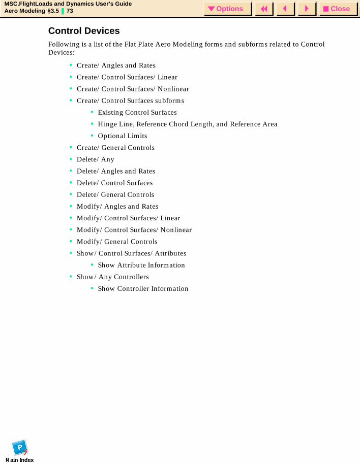
CloseOptionsMSC.FlightLoads and Dynamics User’s GuideAero Modeling §3.5 73 Options
Control Devices Following is a list of the Flat Plate Aero Modeling forms and subforms related to Control Devices:
• Create/Angles and Rates
• Create/Control Surfaces/Linear
• Create/Control Surfaces/Nonlinear
• Create/Control Surfaces subforms
• Existing Control Surfaces
• Hinge Line, Reference Chord Length, and Reference Area
• Optional Limits
• Create/General Controls
• Delete/Any
• Delete/Angles and Rates
• Delete/Control Surfaces
• Delete/General Controls
• Modify/Angles and Rates
• Modify/Control Surfaces/Linear
• Modify/Control Surfaces/Nonlinear
• Modify/General Controls
• Show/Control Surfaces/Attributes
• Show Attribute Information
• Show/Any Controllers
• Show Controller Information
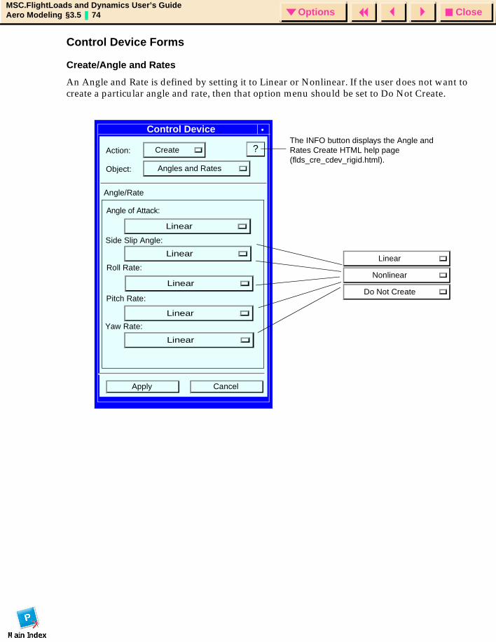
CloseOptionsMSC.FlightLoads and Dynamics User’s GuideAero Modeling §3.5 74 Options
Control Device Forms
Create/Angle and Rates
An Angle and Rate is defined by setting it to Linear or Nonlinear. If the user does not want to create a particular angle and rate, then that option menu should be set to Do Not Create.
Control Device
Action: Create
Object: Angles and Rates
?
Angle of Attack:
Linear
Nonlinear
Do Not Create
Apply Cancel
Side Slip Angle:
Roll Rate:
Pitch Rate:
Yaw Rate:
Angle/Rate
The INFO button displays the Angle and Rates Create HTML help page (flds_cre_cdev_rigid.html).
Linear
Linear
Linear
Linear
Linear
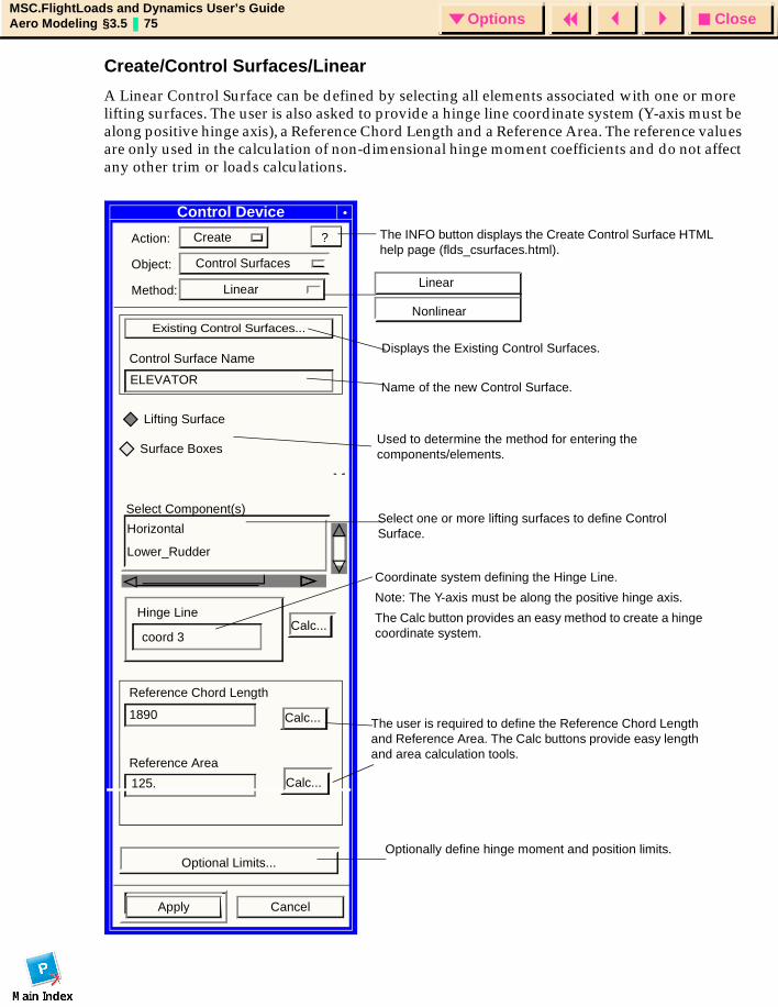
CloseOptionsMSC.FlightLoads and Dynamics User’s GuideAero Modeling §3.5 75 Options
Create/Control Surfaces/Linear
A Linear Control Surface can be defined by selecting all elements associated with one or more lifting surfaces. The user is also asked to provide a hinge line coordinate system (Y-axis must be along positive hinge axis), a Reference Chord Length and a Reference Area. The reference values are only used in the calculation of non-dimensional hinge moment coefficients and do not affect any other trim or loads calculations.
Control Device
Action: Create
Object: Control Surfaces
Method: Linear
Existing Control Surfaces...
Control Surface Name
Select Component(s)
Hinge LineCalc...
Reference Chord Length
1890
Reference Area
Optional Limits...
Apply Cancel
?
ELEVATOR
coord 3
125.
Calc...
Calc...
Displays the Existing Control Surfaces.
Name of the new Control Surface.
Select one or more lifting surfaces to define Control Surface.
Coordinate system defining the Hinge Line.
Note: The Y-axis must be along the positive hinge axis.
The Calc button provides an easy method to create a hinge coordinate system.
The user is required to define the Reference Chord Length and Reference Area. The Calc buttons provide easy length and area calculation tools.
Optionally define hinge moment and position limits.
The INFO button displays the Create Control Surface HTML help page (flds_csurfaces.html).
Horizontal
Lower_Rudder
Linear
Nonlinear
Used to determine the method for entering the components/elements.
Lifting Surface
Surface Boxes
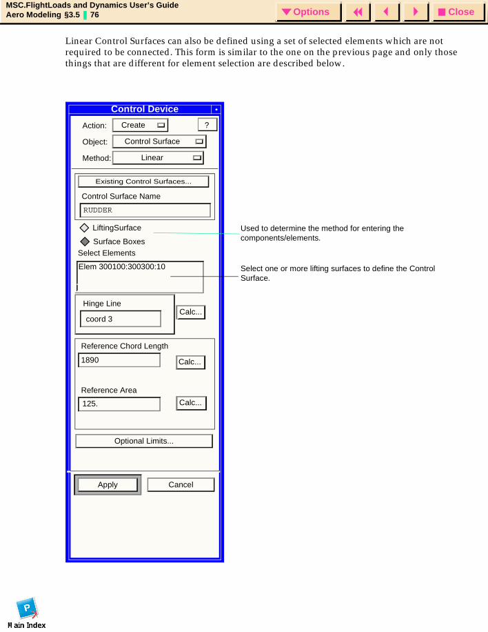
CloseOptionsMSC.FlightLoads and Dynamics User’s GuideAero Modeling §3.5 76 Options
Linear Control Surfaces can also be defined using a set of selected elements which are not required to be connected. This form is similar to the one on the previous page and only those things that are different for element selection are described below.
Control Device
Action: Create
Object: Control Surface
Method: Linear
Existing Control Surfaces...
Control Surface Name
Select Elements
Hinge LineCalc...
Reference Chord Length
1890
Reference Area
Optional Limits...
Apply Cancel
?
RUDDER
coord 3
125.
Calc...
Calc...
Select one or more lifting surfaces to define the Control Surface.
Elem 300100:300300:10
LiftingSurface Used to determine the method for entering the components/elements.Surface Boxes
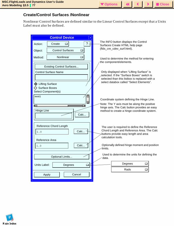
CloseOptionsMSC.FlightLoads and Dynamics User’s GuideAero Modeling §3.5 77 Options
Create/Control Surfaces /Nonlinear
Nonlinear Control Surfaces are defined similar to the Linear Control Surfaces except that a Units Label must also be defined.
Control Device
Action: Create
Object: Control Surfaces
?
CancelApply
Method: Nonlinear
Existing Control Surfaces...
Control Surface Name
test1
Calc...Hinge Line
Reference Chord Length
1.0
Reference Area
1.0
Optional Limits...
Calc...
Calc...
Select Component(s)Surface BoxesLifting Surface
Units Label: Degrees Degrees
Rads
Only displayed when “Lifting Surface” is selected. If the “Surface Boxes” switch is selected than this listbox is replaced with a select databox called “Select Elements”.
Used to determine the units for defining the data.
Used to determine the method for entering the component/elements.
The INFO button displays the Control Surfaces Create HTML help page (flds_cre_cdev_surf.html).
Optionally defined hinge moment and position limits.
The user is required to define the Reference Chord Length and Reference Area. The Calc buttons provide easy length and area calculation tools.
Coordinate system defining the Hinge Line.
Note: The Y axis must be along the positive hinge axis. The Calc button provides an easy method to create a hinge coordinate system.

CloseOptionsMSC.FlightLoads and Dynamics User’s GuideAero Modeling §3.5 78 Options
Create/Control Surfaces Subforms
Existing Control Surfaces. This form simply lists all the Existing Control Surfaces. Selection of a surface does not result in any information being transferred back to the Create/Control Surfaces form.
Select...
Existing Control Surfaces
FLAP
AILERON
RUDDER
Filter *
Close
Select
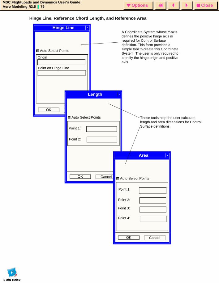
CloseOptionsMSC.FlightLoads and Dynamics User’s GuideAero Modeling §3.5 79 Options
Hinge Line, Reference Chord Length, and Reference Area
Origin
Point on Hinge Line
Auto Select Points
Hinge LineA Coordinate System whose Y-axis defines the positive hinge axis is required for Control Surface definition. This form provides a simple tool to create this Coordinate System. The user is only required to identify the hinge origin and positive axis.
OK Cancel
Auto Select Points
Length
OK Cancel
Auto Select Points
Area
OK Cancel
Point 1:
Point 2:
These tools help the user calculate length and area dimensions for Control Surface definitions.
Point 1:
Point 2:
Point 3:
Point 4:
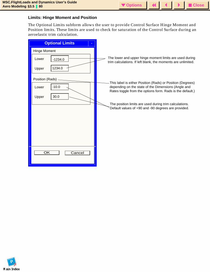
CloseOptionsMSC.FlightLoads and Dynamics User’s GuideAero Modeling §3.5 80 Options
Limits: Hinge Moment and Position
The Optional Limits subform allows the user to provide Control Surface Hinge Moment and Position limits. These limits are used to check for saturation of the Control Surface during an aeroelastic trim calculation.
Hinge Moment
Lower
Upper 1234.0
Position (Rads)
Lower -10.0
Upper
-1234.0
30.0
The lower and upper hinge moment limits are used during trim calculations. If left blank, the moments are unlimited.
The position limits are used during trim calculations. Default values of +90 and -90 degrees are provided.
OK Cancel
Optional Limits
This label is either Position (Rads) or Position (Degrees) depending on the state of the Dimensions (Angle and Rates toggle from the options form. Rads is the default.)
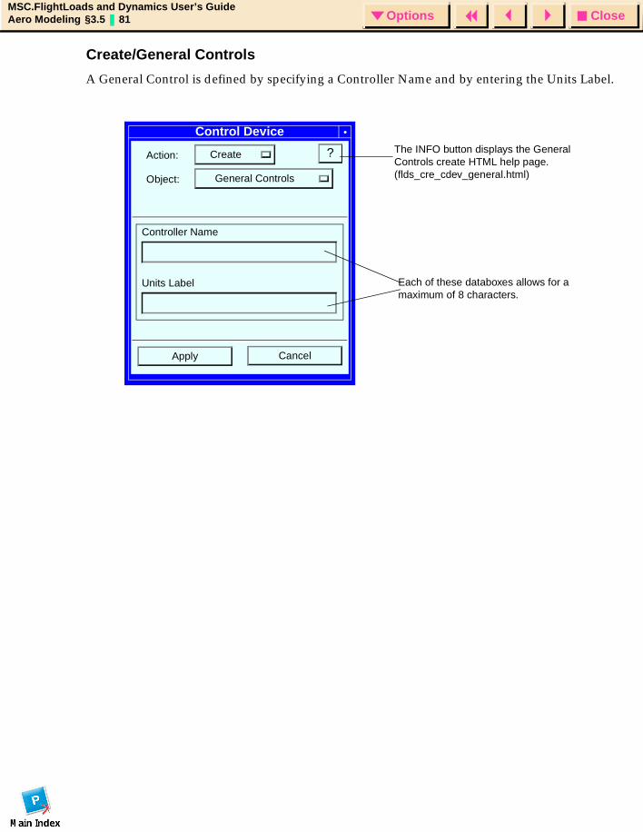
CloseOptionsMSC.FlightLoads and Dynamics User’s GuideAero Modeling §3.5 81 Options
Create/General Controls
A General Control is defined by specifying a Controller Name and by entering the Units Label.
Control Device
Action: Create
Object: General Controls
?
CancelApply
Controller Name
Units Label Each of these databoxes allows for a maximum of 8 characters.
The INFO button displays the General Controls create HTML help page. (flds_cre_cdev_general.html)
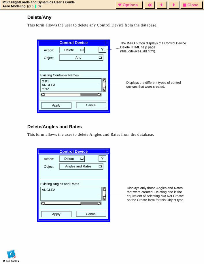
CloseOptionsMSC.FlightLoads and Dynamics User’s GuideAero Modeling §3.5 82 Options
Delete/Any
This form allows the user to delete any Control Device from the database.
Delete/Angles and Rates
This form allows the user to delete Angles and Rates from the database.
Control Device
Action: Delete
Object: Any
?
Existing Controller Names
test1
CancelApply
ANGLEAtest2
Displays the different types of control devices that were created.
The INFO button displays the Control Device Delete HTML help page (flds_cdevices_dd.html).
Control Device
Action: Delete
Object: Angles and Rates
?
Existing Angles and Rates
ANGLEA
CancelApply
Displays only those Angles and Rates that were created. Deleting one is the equivalent of selecting “Do Not Create” on the Create form for this Object type.
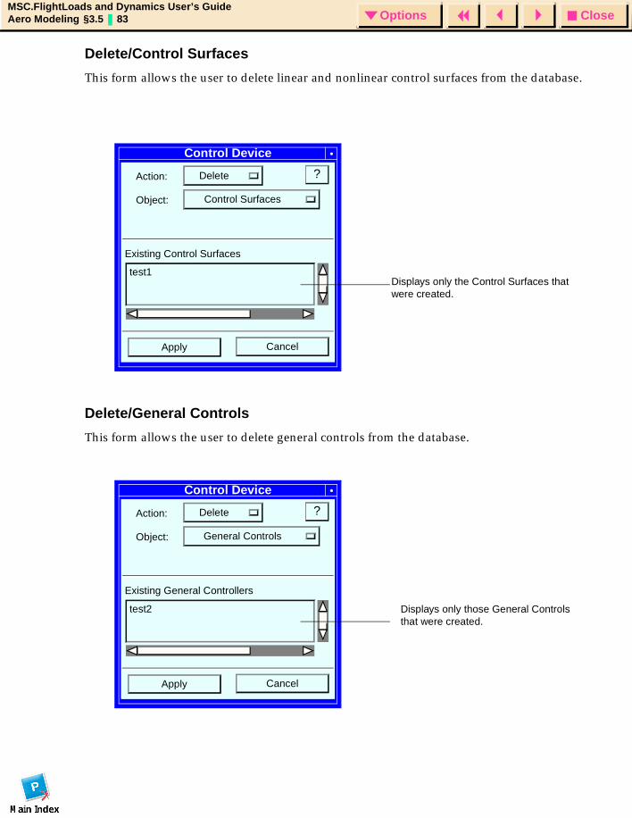
CloseOptionsMSC.FlightLoads and Dynamics User’s GuideAero Modeling §3.5 83 Options
Delete/Control Surfaces
This form allows the user to delete linear and nonlinear control surfaces from the database.
Delete/General Controls
This form allows the user to delete general controls from the database.
Control Device
Action: Delete
Object: Control Surfaces
?
Existing Control Surfaces
test1
CancelApply
Displays only the Control Surfaces that were created.
Control Device
Action: Delete
Object: General Controls
?
Existing General Controllers
test2
CancelApply
Displays only those General Controls that were created.
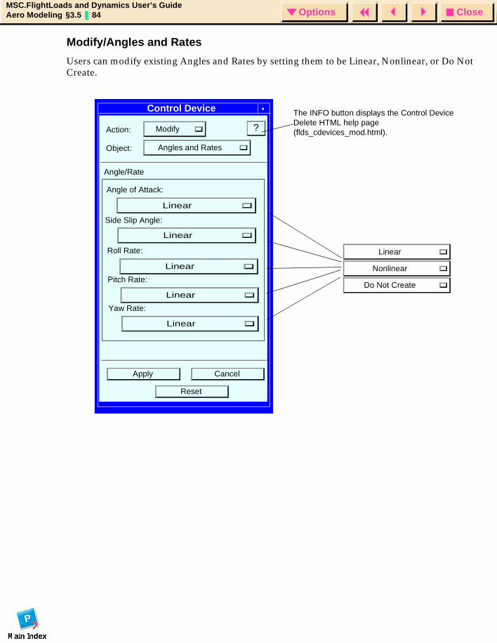
CloseOptionsMSC.FlightLoads and Dynamics User’s GuideAero Modeling §3.5 84 Options
Modify/Angles and Rates
Users can modify existing Angles and Rates by setting them to be Linear, Nonlinear, or Do Not Create.
Control Device
Action: Modify
Object: Angles and Rates
?
Angle of Attack:
Linear
Nonlinear
Do Not Create
Apply Cancel
Side Slip Angle:
Roll Rate:
Pitch Rate:
Yaw Rate:
Angle/Rate
Reset
The INFO button displays the Control Device Delete HTML help page (flds_cdevices_mod.html).
Linear
Linear
Linear
Linear
Linear
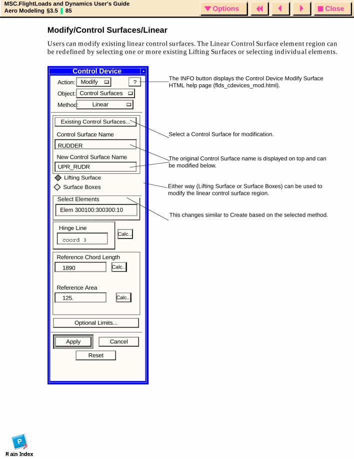
CloseOptionsMSC.FlightLoads and Dynamics User’s GuideAero Modeling §3.5 85 Options
Modify/Control Surfaces/Linear
Users can modify existing linear control surfaces. The Linear Control Surface element region can be redefined by selecting one or more existing Lifting Surfaces or selecting individual elements.
Action: Modify
Object: Control Surfaces
Method: Linear
Existing Control Surfaces...
Control Surface Name
New Control Surface Name
Calc...
Reference Chord Length
Calc...
Reference Area
Calc...
Optional Limits...
Apply Cancel
Reset
Select Elements
Hinge Line
?
RUDDER
UPR_RUDR
Elem 300100:300300:10
coord 3
1890
125.
Select a Control Surface for modification.
The original Control Surface name is displayed on top and can be modified below.
The INFO button displays the Control Device Modify Surface HTML help page (flds_cdevices_mod.html).
Control Device
This changes similar to Create based on the selected method.
Lifting Surface
Surface Boxes Either way (Lifting Surface or Surface Boxes) can be used to modify the linear control surface region.
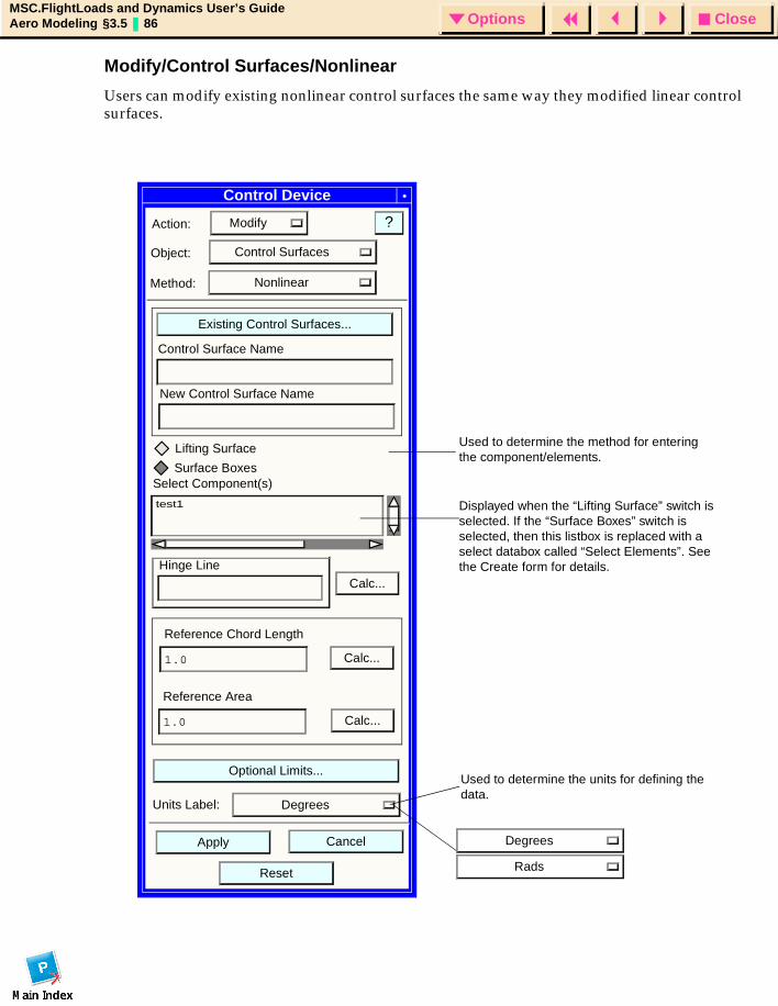
CloseOptionsMSC.FlightLoads and Dynamics User’s GuideAero Modeling §3.5 86 Options
Modify/Control Surfaces/Nonlinear
Users can modify existing nonlinear control surfaces the same way they modified linear control surfaces.
Control Device
Action: Modify
Object: Control Surfaces
?
CancelApply
Method: Nonlinear
Existing Control Surfaces...
Control Surface Name
test1
Calc...Hinge Line
Reference Chord Length
1.0
Reference Area
1.0
Optional Limits...
Calc...
Calc...
Select Component(s)Surface Boxes
New Control Surface Name
Reset
Degrees
Rads
Units Label: Degrees
Used to determine the method for entering the component/elements.
Displayed when the “Lifting Surface” switch is selected. If the “Surface Boxes” switch is selected, then this listbox is replaced with a select databox called “Select Elements”. See the Create form for details.
Used to determine the units for defining the data.
Lifting Surface
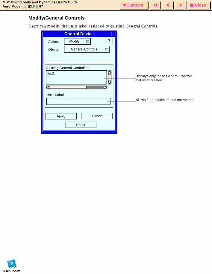
CloseOptionsMSC.FlightLoads and Dynamics User’s GuideAero Modeling §3.5 87 Options
Modify/General Controls
Users can modify the units label assigned to existing General Controls.
Control Device
Action: Modify
Object: General Controls
?
CancelApply
Units Label
test1
Existing General Controllers
Reset
Displays only those General Controls that were created.
Allows for a maximum of 8 characters.
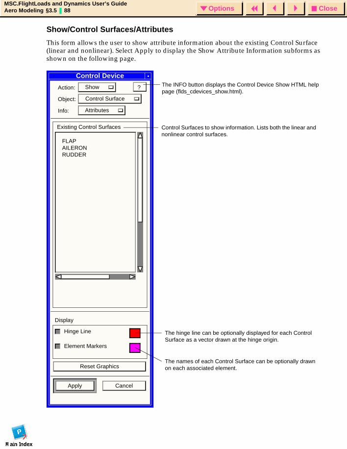
CloseOptionsMSC.FlightLoads and Dynamics User’s GuideAero Modeling §3.5 88 Options
Show/Control Surfaces/Attributes
This form allows the user to show attribute information about the existing Control Surface (linear and nonlinear). Select Apply to display the Show Attribute Information subforms as shown on the following page.
Control Device
Action: Show
Object: Control Surface
Info: Attributes
Existing Control Surfaces
Display
Hinge Line
Reset Graphics
Apply Cancel
?
FLAPAILERONRUDDER
Control Surfaces to show information. Lists both the linear and nonlinear control surfaces.
The hinge line can be optionally displayed for each Control Surface as a vector drawn at the hinge origin.
Element Markers
The names of each Control Surface can be optionally drawn on each associated element.
The INFO button displays the Control Device Show HTML help page (flds_cdevices_show.html).
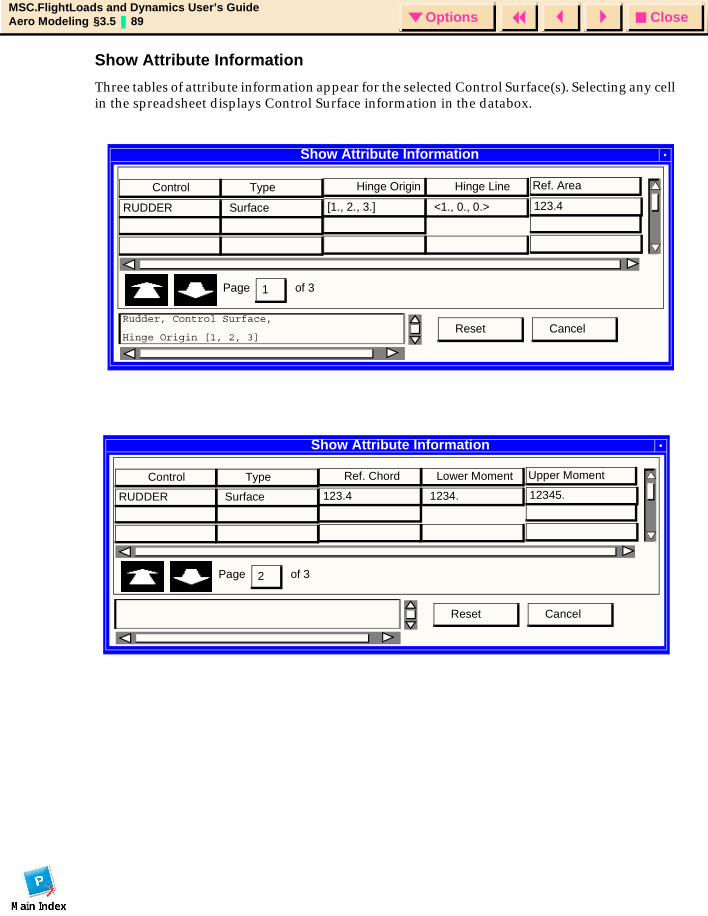
CloseOptionsMSC.FlightLoads and Dynamics User’s GuideAero Modeling §3.5 89 Options
Show Attribute Information
Three tables of attribute information appear for the selected Control Surface(s). Selecting any cell in the spreadsheet displays Control Surface information in the databox.
Show Attribute Information
Page
Control Type
RUDDER Surface
Hinge Origin Hinge Line
[1., 2., 3.] <1., 0., 0.>
Ref. Area
123.4
of 3
Cancel
1
ResetRudder, Control Surface,
Hinge Origin [1, 2, 3]
Show Attribute Information
Page
Control Type
RUDDER Surface
Ref. Chord Lower Moment
123.4 1234.
Upper Moment
12345.
of 3
Cancel
2
Reset
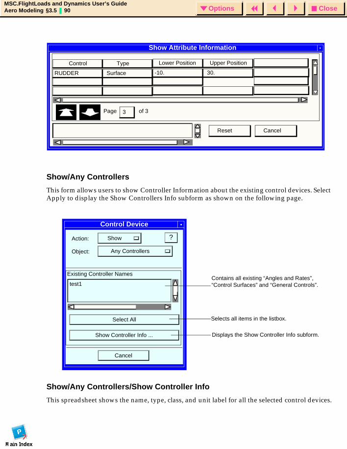
CloseOptionsMSC.FlightLoads and Dynamics User’s GuideAero Modeling §3.5 90 Options
Show/Any Controllers
This form allows users to show Controller Information about the existing control devices. Select Apply to display the Show Controllers Info subform as shown on the following page.
Show/Any Controllers/Show Controller Info
This spreadsheet shows the name, type, class, and unit label for all the selected control devices.
Show Attribute Information
Page
Control Type
RUDDER Surface
Lower Position Upper Position
-10. 30.
of 3
Cancel
3
Reset
Control Device
Action: Show
Object: Any Controllers
?
Existing Controller Names
test1
Select All
Show Controller Info ...
Cancel
Contains all existing “Angles and Rates”, “Control Surfaces” and “General Controls”.
Selects all items in the listbox.
Displays the Show Controller Info subform.
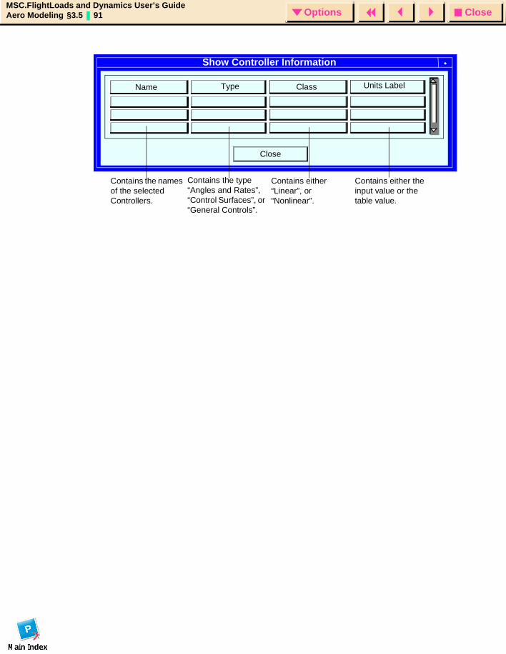
CloseOptionsMSC.FlightLoads and Dynamics User’s GuideAero Modeling §3.5 91 Options
Show Controller Information
Close
Name Type Class Units Label
Contains the names of the selected Controllers.
Contains the type “Angles and Rates”, “Control Surfaces”, or “General Controls”.
Contains either “Linear”, or “Nonlinear”.
Contains either the input value or the table value.
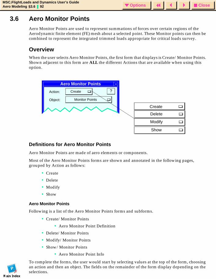
CloseOptionsMSC.FlightLoads and Dynamics User’s GuideAero Modeling §3.6 92 Options
3.6 Aero Monitor PointsAero Monitor Points are used to represent summations of forces over certain regions of the Aerodynamic finite element (FE) mesh about a selected point. These Monitor points can then be combined to represent the integrated trimmed loads appropriate for critical loads survey.
OverviewWhen the user selects Aero Monitor Points, the first form that displays is Create/Monitor Points. Shown adjacent to this form are ALL the different Actions that are available when using this option.
Definitions for Aero Monitor Points
Aero Monitor Points are made of aero elements or components.
Most of the Aero Monitor Points forms are shown and annotated in the following pages, grouped by Action as follows:
• Create
• Delete
• Modify
• Show
Aero Monitor Points
Following is a list of the Aero Monitor Points forms and subforms.
• Create/Monitor Points
• Aero Monitor Point Definition
• Delete/Monitor Points
• Modify/Monitor Points
• Show/Monitor Points
• Aero Monitor Point Info
To complete the forms, the user would start by selecting values at the top of the form, choosing an action and then an object. The fields on the remainder of the form display depending on the selections.
Aero Monitor Points
Action: Create
Object: Monitor Points
?
Create
Delete
Modify
Show
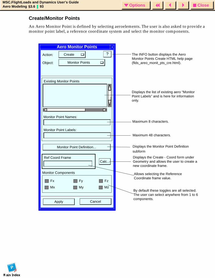
CloseOptionsMSC.FlightLoads and Dynamics User’s GuideAero Modeling §3.6 93 Options
Create/Monitor Points
An Aero Monitor Point is defined by selecting aeroelements. The user is also asked to provide a monitor point label, a reference coordinate system and select the monitor components.
Aero Monitor Points
Action: Create
Object: Monitor Points
?
Monitor Point Definition...
CancelApply
Ref Coord Frame
Existing Monitor Points
Monitor Point Labels:
Monitor Point Names:
Calc...
Monitor Components
Fx
Mx
Fz
Mz
Fy
My
Displays the list of existing aero “Monitor Point Labels” and is here for information only.
Maximum 8 characters.
Maximum 48 characters.
Displays the Monitor Point Definition subform
Displays the Create - Coord form under Geometry and allows the user to create a new coordinate frame.
Allows selecting the Reference Coordinate frame value.
By default these toggles are all selected. The user can select anywhere from 1 to 6 components.
The INFO button displays the Aero Monitor Points Create HTML help page (flds_areo_monit_pts_cre.html).
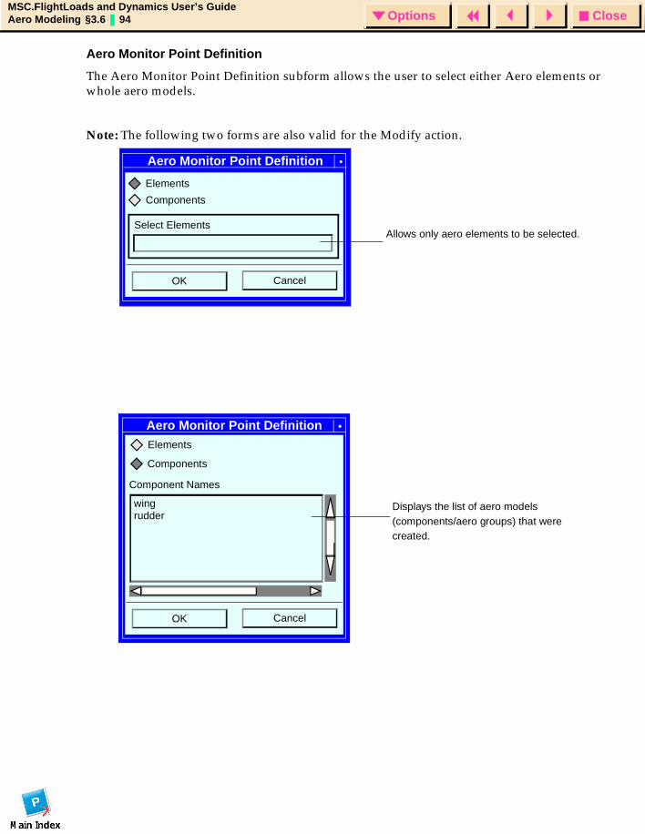
CloseOptionsMSC.FlightLoads and Dynamics User’s GuideAero Modeling §3.6 94 Options
Aero Monitor Point Definition
The Aero Monitor Point Definition subform allows the user to select either Aero elements or whole aero models.
Note: The following two forms are also valid for the Modify action.
Aero Monitor Point Definition
CancelOK
Components
Elements
Select ElementsAllows only aero elements to be selected.
Aero Monitor Point Definition
Component Names
wing
CancelOK
Elements
Components
rudderDisplays the list of aero models (components/aero groups) that were created.
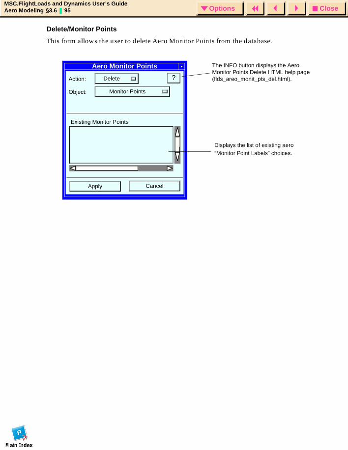
CloseOptionsMSC.FlightLoads and Dynamics User’s GuideAero Modeling §3.6 95 Options
Delete/Monitor Points
This form allows the user to delete Aero Monitor Points from the database.
Aero Monitor Points
Action: Delete
Object: Monitor Points
?
CancelApply
Existing Monitor Points
Displays the list of existing aero “Monitor Point Labels” choices.
The INFO button displays the Aero Monitor Points Delete HTML help page (flds_areo_monit_pts_del.html).
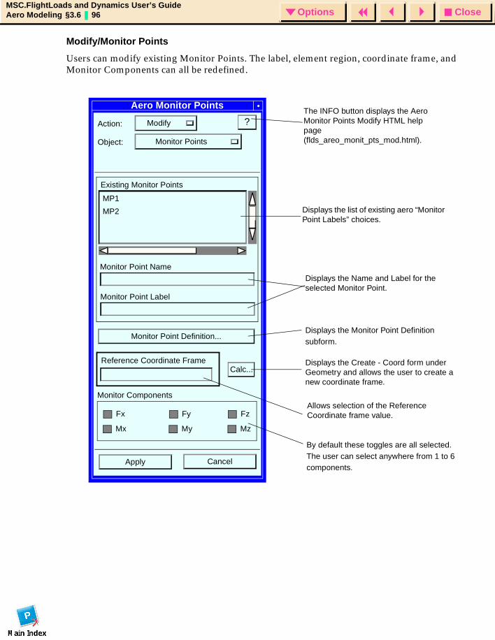
CloseOptionsMSC.FlightLoads and Dynamics User’s GuideAero Modeling §3.6 96 Options
Modify/Monitor Points
Users can modify existing Monitor Points. The label, element region, coordinate frame, and Monitor Components can all be redefined.
Aero Monitor Points
Action: Modify
Object: Monitor Points
?
Monitor Point Definition...
CancelApply
Reference Coordinate Frame
Existing Monitor Points
Monitor Point Label
Monitor Point Name
Calc...
Monitor Components
Fx
Mx
Fz
Mz
Fy
My
Displays the list of existing aero “Monitor Point Labels” choices.
Displays the Monitor Point Definition subform.
Displays the Create - Coord form under Geometry and allows the user to create a new coordinate frame.
Allows selection of the Reference Coordinate frame value.
By default these toggles are all selected. The user can select anywhere from 1 to 6 components.
The INFO button displays the Aero Monitor Points Modify HTML help page (flds_areo_monit_pts_mod.html).
MP1
MP2
Displays the Name and Label for the selected Monitor Point.
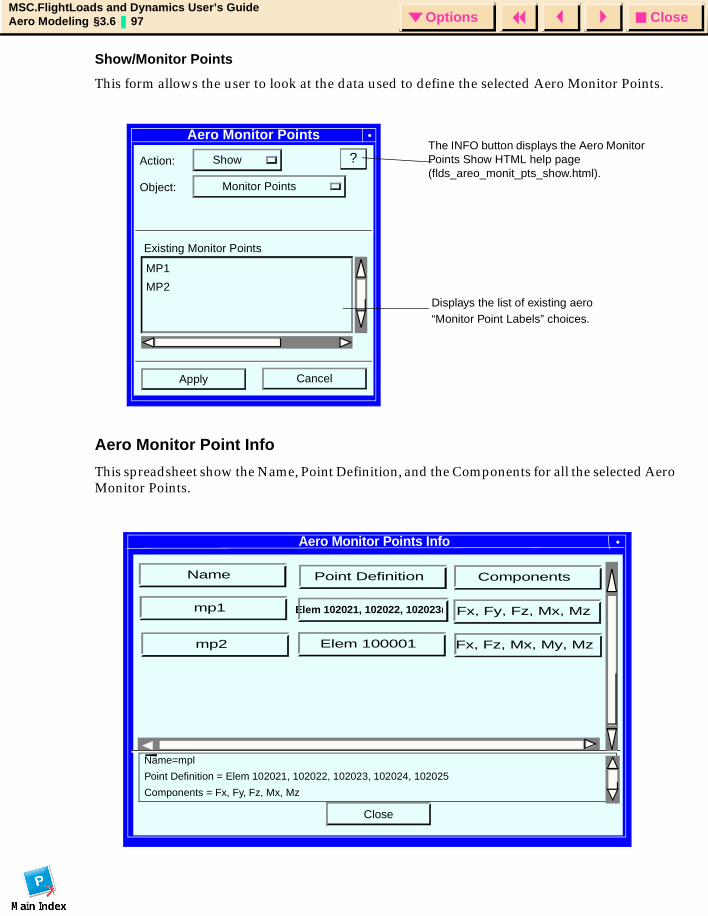
CloseOptionsMSC.FlightLoads and Dynamics User’s GuideAero Modeling §3.6 97 Options
Show/Monitor Points
This form allows the user to look at the data used to define the selected Aero Monitor Points.
Aero Monitor Point Info
This spreadsheet show the Name, Point Definition, and the Components for all the selected Aero Monitor Points.
Aero Monitor Points
Action: Show
Object: Monitor Points
?
CancelApply
Existing Monitor Points
Displays the list of existing aero “Monitor Point Labels” choices.
The INFO button displays the Aero Monitor Points Show HTML help page (flds_areo_monit_pts_show.html).
MP1
MP2
Aero Monitor Points Info
Close
Name=mpl
Point Definition = Elem 102021, 102022, 102023, 102024, 102025
Components = Fx, Fy, Fz, Mx, Mz
Point Definition
Elem 102021, 102022, 102023l
Elem 100001 Fx, Fz, Mx, My, Mz
Fx, Fy, Fz, Mx, Mz
Components
mp1
Name
mp2

CloseOptionsMSC.FlightLoads and Dynamics User’s GuideAero Modeling §3.6 98 Options
CloseOptionsMSC.FlightLoads and Dynamics User’s GuideAerodynamics § 99 Options
MSC.FlightLoads and Dynamics User’s Guide
CHAPTER
4 Aerodynamics
Introduction
Global Data
Steady Aerodynamics
Unsteady Aerodynamics
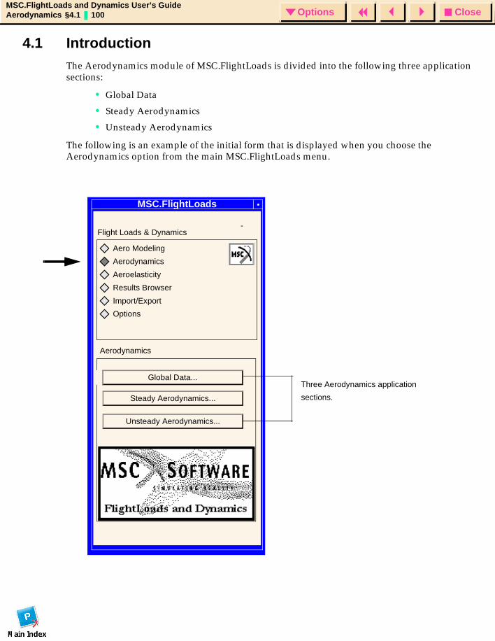
CloseOptionsMSC.FlightLoads and Dynamics User’s GuideAerodynamics §4.1 100 Options
4.1 IntroductionThe Aerodynamics module of MSC.FlightLoads is divided into the following three application sections:
• Global Data
• Steady Aerodynamics
• Unsteady Aerodynamics
The following is an example of the initial form that is displayed when you choose the Aerodynamics option from the main MSC.FlightLoads menu.
MSC.FLD
MSC.FlightLoads
-Flight Loads & Dynamics
Aeroelasticity
Results Browser
Import/Export
Options
Aerodynamics
Steady Aerodynamics...
Unsteady Aerodynamics...
Aerodynamics
Aero Modeling
Global Data...Three Aerodynamics application
sections.
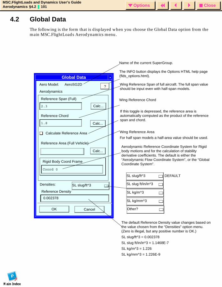
CloseOptionsMSC.FlightLoads and Dynamics User’s GuideAerodynamics §4.2 101 Options
4.2 Global DataThe following is the form that is displayed when you choose the Global Data option from the main MSC.FlightLoads Aerodynamics menu.
Global Data
Aerodynamics
Reference Span (Full)
2.3 Calc...
Reference Chord
1.8
Calculate Reference Area
Reference Area (Full Vehicle)
Rigid Body Coord Frame
Coord 0
OK Cancel
Aero Model: AeroSG2D
Densities:
0.002378
Reference Density
Wing Reference Area
For half span models a half-area value should be used.
Calc...
SL slug/ft^3
The default Reference Density value changes based on the value chosen from the “Densities” option menu. (Zero is illegal, but any positive number is OK.)
SL slug/ft^3 = 0.002378
SL slug ft/in/in^3 = 1.1468E-7
SL kg/m^3 = 1.226
SL kg/mm^3 = 1.226E-9
Wing Reference Span of full aircraft. The full span value should be input even with half-span models.
Wing Reference Chord
If this toggle is depressed, the reference area is automatically computed as the product of the reference span and chord.
Aerodynamic Reference Coordinate System for Rigid body motions and for the calculation of stability derivative coefficients. The default is either the “Aerodynamic Flow Coordinate System”, or the “Global Coordinate System”.
Calc...
?
The INFO button displays the Options HTML help page (flds_options.html).
Other?
SL kg/m^3
SL slug ft/in/in^3
SL kg/mm^3
SL slug/ft^3 DEFAULT
Name of the current SuperGroup.
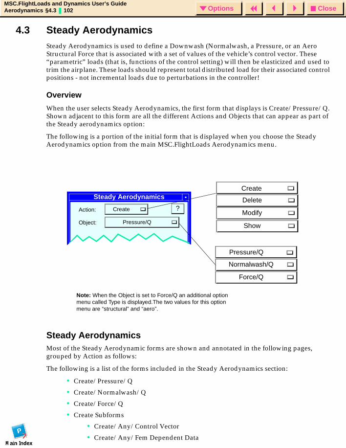
CloseOptionsMSC.FlightLoads and Dynamics User’s GuideAerodynamics §4.3 102 Options
4.3 Steady AerodynamicsSteady Aerodynamics is used to define a Downwash (Normalwash, a Pressure, or an Aero Structural Force that is associated with a set of values of the vehicle’s control vector. These “parametric” loads (that is, functions of the control setting) will then be elasticized and used to trim the airplane. These loads should represent total distributed load for their associated control positions - not incremental loads due to perturbations in the controller!
Overview
When the user selects Steady Aerodynamics, the first form that displays is Create/Pressure/Q. Shown adjacent to this form are all the different Actions and Objects that can appear as part of the Steady aerodynamics option:
The following is a portion of the initial form that is displayed when you choose the Steady Aerodynamics option from the main MSC.FlightLoads Aerodynamics menu.
Steady Aerodynamics Most of the Steady Aerodynamic forms are shown and annotated in the following pages, grouped by Action as follows:
The following is a list of the forms included in the Steady Aerodynamics section:
• Create/Pressure/Q
• Create/Normalwash/Q
• Create/Force/Q
• Create Subforms
• Create/Any/Control Vector
• Create/Any/Fem Dependent Data
Steady Aerodynamics
Action: Create
Object: Pressure/Q
?
Pressure/Q
Normalwash/Q
Force/Q
Create
Delete
Modify
Show
Note: When the Object is set to Force/Q an additional option menu called Type is displayed.The two values for this option menu are “structural” and “aero”.

CloseOptionsMSC.FlightLoads and Dynamics User’s GuideAerodynamics §4.3 103 Options
• Delete/Any
• Modify/Pressure/Q
• Modify/Normalwash/Q
• Modify/Force/Q
• Show/Any/Fringe
• Show Subforms
• Show/Any/Fringe/Fringe Attributes
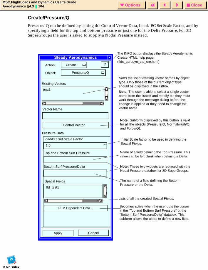
CloseOptionsMSC.FlightLoads and Dynamics User’s GuideAerodynamics §4.3 104 Options
Create/Pressure/Q
Pressure/Q can be defined by setting the Control Vector Data, Load/BC Set Scale Factor, and by specifying a field for the top and bottom pressure or just one for the Delta Pressure. For 3D SuperGroups the user is asked to supply a Nodal Pressure instead.
Steady Aerodynamics
Action: Create
Object: Pressure/Q
?
Existing Vectors
test1
Vector Name
Control Vector ...
CancelApply
Pressure Data
Load/BC Set Scale Factor
Top and Bottom Surf Pressure
Bottom Surf Pressure/Delta
Spatial Fields
fld_test1
FEM Dependent Data...
1.0
Becomes active when the user puts the cursor in the “Top and Bottom Surf Pressure” or the “Bottom Surf Pressure/Delta” databox. This subform allows the users to define a new field.
The name of a field defining the Bottom Pressure or the Delta.
Initial Scale factor to be used in defining the Spatial Fields.
Note: Subform displayed by this button is valid for all the objects (Pressure/Q, Normalwash/Q, and Force/Q).
Sorts the list of existing vector names by object type. Only those of the current object type should be displayed in the listbox.
Note: The user is able to select a single vector name from the listbox and modify but they must work through the message dialog before the change is applied or they need to change the vector name.
Name of a field defining the Top Pressure. This value can be left blank when defining a Delta
Lists of all the created Spatial Fields.
The INFO button displays the Steady Aerodynamic Create HTML help page. (flds_aerodyn_std_cre.html)
Note: These two widgets are replaced with the Nodal Pressure databox for 3D SuperGroups.
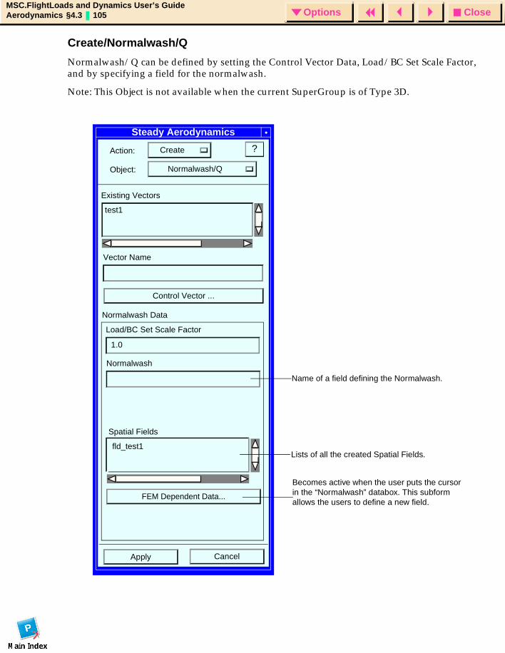
CloseOptionsMSC.FlightLoads and Dynamics User’s GuideAerodynamics §4.3 105 Options
Create/Normalwash/Q
Normalwash/Q can be defined by setting the Control Vector Data, Load/BC Set Scale Factor, and by specifying a field for the normalwash.
Note: This Object is not available when the current SuperGroup is of Type 3D.
Steady Aerodynamics
Action: Create
Object: Normalwash/Q
?
Existing Vectors
test1
Vector Name
Control Vector ...
CancelApply
Normalwash Data
Load/BC Set Scale Factor
Normalwash
Spatial Fields
fld_test1
FEM Dependent Data...
1.0
Name of a field defining the Normalwash.
Lists of all the created Spatial Fields.
Becomes active when the user puts the cursor in the “Normalwash” databox. This subform allows the users to define a new field.
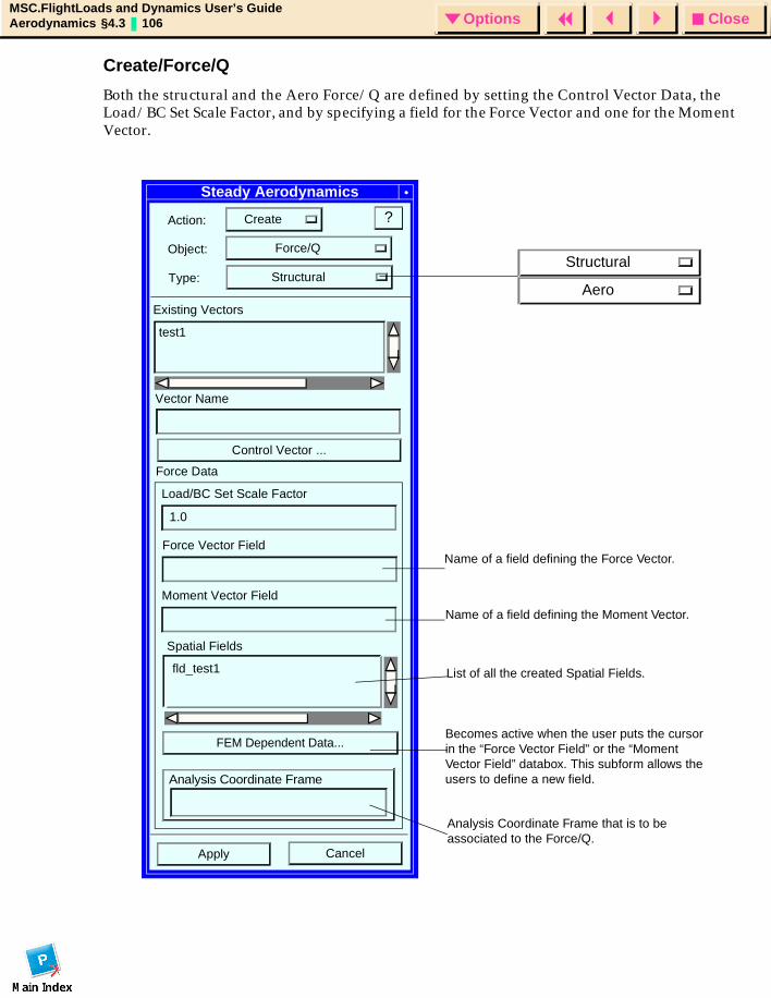
CloseOptionsMSC.FlightLoads and Dynamics User’s GuideAerodynamics §4.3 106 Options
Create/Force/Q
Both the structural and the Aero Force/Q are defined by setting the Control Vector Data, the Load/BC Set Scale Factor, and by specifying a field for the Force Vector and one for the Moment Vector.
Steady Aerodynamics
Action: Create
Object: Force/Q
?
Existing Vectors
test1
Vector Name
Control Vector ...
CancelApply
Force Data
Load/BC Set Scale Factor
Force Vector Field
Moment Vector Field
Spatial Fields
fld_test1
FEM Dependent Data...
1.0
Type: StructuralStructural
Aero
Analysis Coordinate Frame
Name of a field defining the Force Vector.
Name of a field defining the Moment Vector.
List of all the created Spatial Fields.
Becomes active when the user puts the cursor in the “Force Vector Field” or the “Moment Vector Field” databox. This subform allows the users to define a new field.
Analysis Coordinate Frame that is to be associated to the Force/Q.
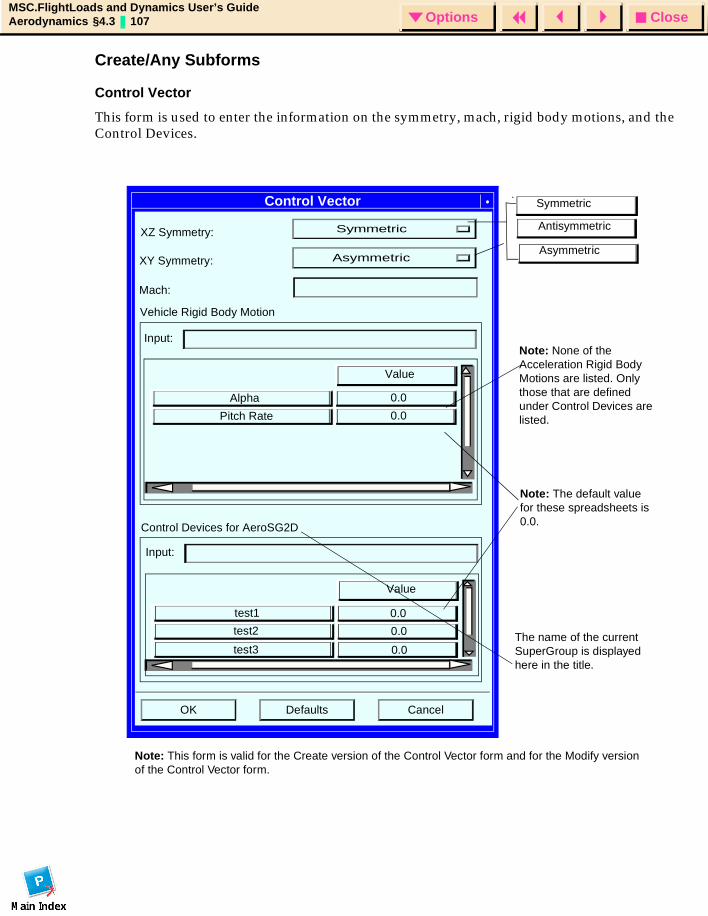
CloseOptionsMSC.FlightLoads and Dynamics User’s GuideAerodynamics §4.3 107 Options
Create/Any Subforms
Control Vector
This form is used to enter the information on the symmetry, mach, rigid body motions, and the Control Devices.
Control Vector
XZ Symmetry: Symmetric
XY Symmetry: Asymmetric
Mach:
Vehicle Rigid Body Motion
Control Devices for AeroSG2D
OK Defaults Cancel
Value
Alpha
Pitch Rate
Value
test1
test2
test3
0.0
0.0
Input:
Input:
0.0
0.0
0.0
Note: This form is valid for the Create version of the Control Vector form and for the Modify version of the Control Vector form.
Note: The default value for these spreadsheets is 0.0.
Note: None of the Acceleration Rigid Body Motions are listed. Only those that are defined under Control Devices are listed.
The name of the current SuperGroup is displayed here in the title.
Symmetric
Antisymmetric
Asymmetric
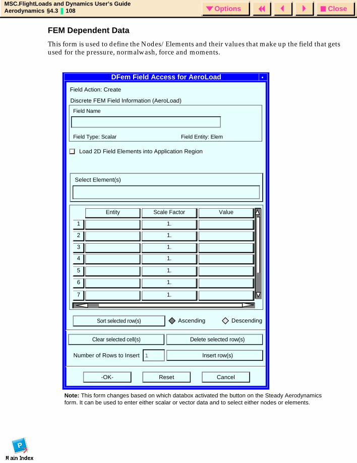
CloseOptionsMSC.FlightLoads and Dynamics User’s GuideAerodynamics §4.3 108 Options
FEM Dependent Data
This form is used to define the Nodes/Elements and their values that make up the field that gets used for the pressure, normalwash, force and moments.
DFem Field Access for AeroLoad
Field Action: Create
Discrete FEM Field Information (AeroLoad)
Field Name
Field Type: Scalar Field Entity: Elem
Load 2D Field Elements into Application Region
Select Element(s)
Ascending Descending
Number of Rows to Insert 1
-OK- Reset Cancel
Insert row(s)
Clear selected cell(s) Delete selected row(s)
Sort selected row(s)
Entity ValueScale Factor
1.
1.
1.
1.
1.
1.
1.
1
2
3
4
5
6
7
Note: This form changes based on which databox activated the button on the Steady Aerodynamics form. It can be used to enter either scalar or vector data and to select either nodes or elements.
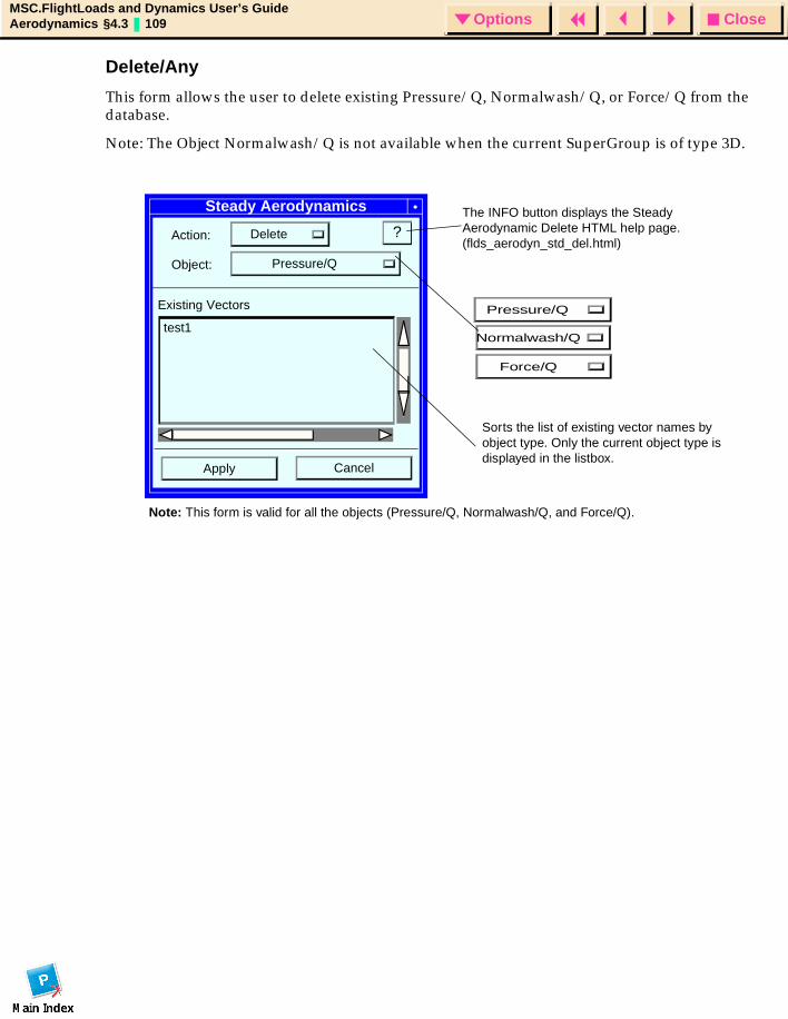
CloseOptionsMSC.FlightLoads and Dynamics User’s GuideAerodynamics §4.3 109 Options
Delete/Any
This form allows the user to delete existing Pressure/Q, Normalwash/Q, or Force/Q from the database.
Note: The Object Normalwash/Q is not available when the current SuperGroup is of type 3D.
Steady Aerodynamics
Action: Delete
Object: Pressure/Q
?
Existing Vectors
test1
CancelApply
Note: This form is valid for all the objects (Pressure/Q, Normalwash/Q, and Force/Q).
Pressure/Q
Normalwash/Q
Force/Q
The INFO button displays the Steady Aerodynamic Delete HTML help page. (flds_aerodyn_std_del.html)
Sorts the list of existing vector names by object type. Only the current object type is displayed in the listbox.
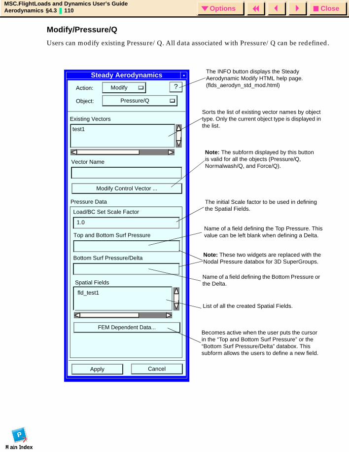
CloseOptionsMSC.FlightLoads and Dynamics User’s GuideAerodynamics §4.3 110 Options
Modify/Pressure/Q
Users can modify existing Pressure/Q. All data associated with Pressure/Q can be redefined.
Steady Aerodynamics
Action: Modify
Object: Pressure/Q
?
Existing Vectors
test1
Vector Name
Modify Control Vector ...
CancelApply
Pressure Data
Load/BC Set Scale Factor
Top and Bottom Surf Pressure
Bottom Surf Pressure/Delta
Spatial Fields
fld_test1
FEM Dependent Data...
1.0
Sorts the list of existing vector names by object type. Only the current object type is displayed in the list.
The initial Scale factor to be used in defining the Spatial Fields.
Name of a field defining the Top Pressure. This value can be left blank when defining a Delta.
Name of a field defining the Bottom Pressure or the Delta.
List of all the created Spatial Fields.
Becomes active when the user puts the cursor in the “Top and Bottom Surf Pressure” or the “Bottom Surf Pressure/Delta” databox. This subform allows the users to define a new field.
Note: The subform displayed by this button is valid for all the objects (Pressure/Q, Normalwash/Q, and Force/Q).
The INFO button displays the Steady Aerodynamic Modify HTML help page. (flds_aerodyn_std_mod.html)
Note: These two widgets are replaced with the Nodal Pressure databox for 3D SuperGroups.
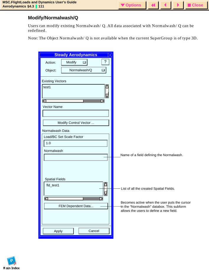
CloseOptionsMSC.FlightLoads and Dynamics User’s GuideAerodynamics §4.3 111 Options
Modify/Normalwash/Q
Users can modify existing Normalwash/Q. All data associated with Normalwash/Q can be redefined.
Note: The Object Normalwash/Q is not available when the current SuperGroup is of type 3D.
Steady Aerodynamics
Action: Modify
Object: Normalwash/Q
?
Existing Vectors
test1
Vector Name
Modify Control Vector ...
CancelApply
Normalwash Data
Load/BC Set Scale Factor
Normalwash
Spatial Fields
fld_test1
FEM Dependent Data...
1.0
Name of a field defining the Normalwash.
List of all the created Spatial Fields.
Becomes active when the user puts the cursor in the “Normalwash” databox. This subform allows the users to define a new field.
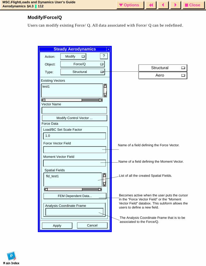
CloseOptionsMSC.FlightLoads and Dynamics User’s GuideAerodynamics §4.3 112 Options
Modify/Force/Q
Users can modify existing Force/Q. All data associated with Force/Q can be redefined.
Steady Aerodynamics
Action: Modify
Object: Force/Q
?
Existing Vectors
test1
Vector Name
Modify Control Vector ...
CancelApply
Force Data
Load/BC Set Scale Factor
Force Vector Field
Moment Vector Field
Spatial Fields
fld_test1
FEM Dependent Data...
1.0
Type: StructuralStructural
Aero
Analysis Coordinate Frame
Name of a field defining the Force Vector.
Name of a field defining the Moment Vector.
List of all the created Spatial Fields.
Becomes active when the user puts the cursor in the “Force Vector Field” or the “Moment Vector Field” databox. This subform allows the users to define a new field.
The Analysis Coordinate Frame that is to be associated to the Force/Q.
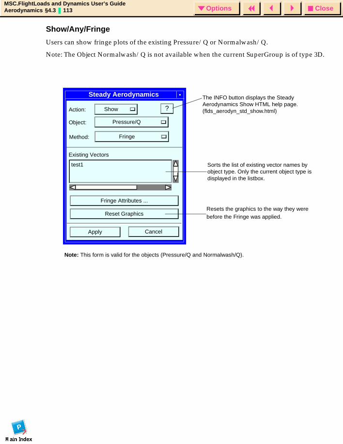
CloseOptionsMSC.FlightLoads and Dynamics User’s GuideAerodynamics §4.3 113 Options
Show/Any/Fringe
Users can show fringe plots of the existing Pressure/Q or Normalwash/Q.
Note: The Object Normalwash/Q is not available when the current SuperGroup is of type 3D.
Steady Aerodynamics
Action: Show
Object: Pressure/Q
?
Existing Vectors
test1
Fringe Attributes ...
Reset Graphics
CancelApply
Method: Fringe
Note: This form is valid for the objects (Pressure/Q and Normalwash/Q).
Sorts the list of existing vector names by object type. Only the current object type is displayed in the listbox.
Resets the graphics to the way they were before the Fringe was applied.
The INFO button displays the Steady Aerodynamics Show HTML help page. (flds_aerodyn_std_show.html)
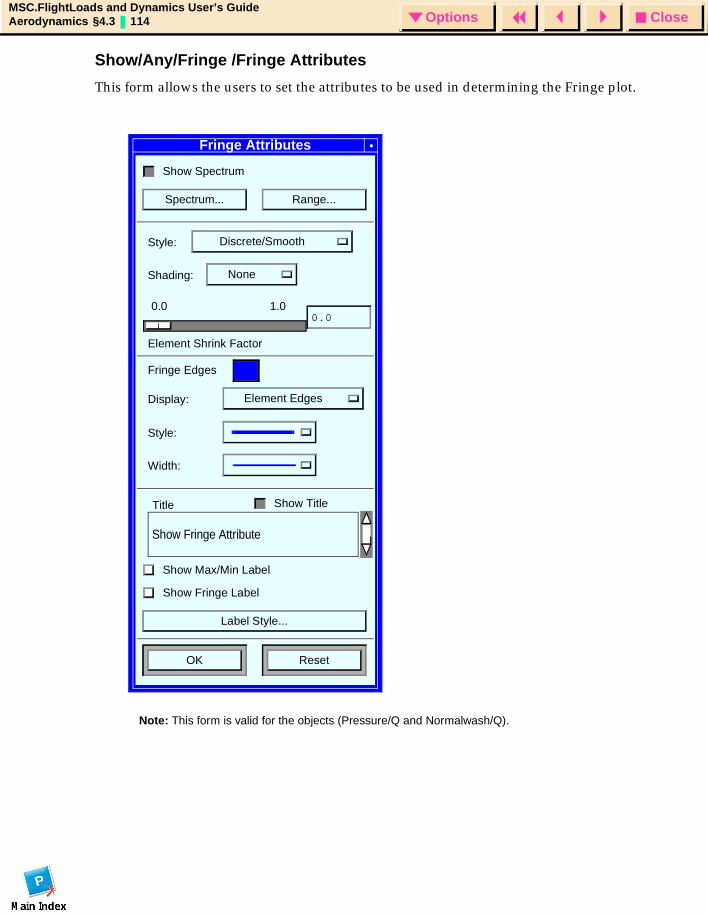
CloseOptionsMSC.FlightLoads and Dynamics User’s GuideAerodynamics §4.3 114 Options
Show/Any/Fringe /Fringe Attributes
This form allows the users to set the attributes to be used in determining the Fringe plot.
Fringe Attributes
Show Spectrum
Spectrum... Range...
Style: Discrete/Smooth
Shading: None
Element Shrink Factor
1.00.00.0
Fringe Edges
Display: Element Edges
Style:
Width:
Show TitleTitle
Show Fringe Attribute
Show Max/Min Label
Show Fringe Label
Label Style...
OK Reset
Note: This form is valid for the objects (Pressure/Q and Normalwash/Q).
CloseOptionsMSC.FlightLoads and Dynamics User’s GuideAerodynamics §4.4 115 Options
4.4 Unsteady AerodynamicsIn order to perform dynamic aeroelastic stability (Flutter) and response analysis, first define the aerodynamics at specific Mach numbers, M (ratio of speed to the speed of sound) and Reduced Frequencies, k (nondimensional frequency). In MSC.FLD, these defined data are used as the basis for interpolation to user-defined analysis points. The interpolation is performed on the union of all Mach-Frequency Pair Sets that are used in any given run. Under user control, these data may be interpolated within a Mach number (e.g., frequencies only) or across all Mach-k pairs in the union of sets. Typically only 6 to 10 frequencies per Mach number are required for an adequate interpolation. Too many frequencies can actually degrade the quality of the interpolation!
In this form you are able to define named sets of Mach Frequency pairs. You will then select these sets on a subcase by subcase basis in Flutter Subcase Creation.
The basic approach is to define ranges of values and select Uniform, Biased or Tabular methods to fill interstitial values. The Mach numbers are typically a single value per set, so it is possible to merely specify a Minimum value if only one is desired. The Reduced Frequency may be defined nondimensionally (that is, by k value) or dimesionally by combinations of cyclic frequency (in Hertz) and dimensional speed. The k value is related to these dimensional parameters by the equation:
where F is the cyclic frequency, b is the reference chord length from the Global Data and V is the dimensional Velocity.
You may choose dimensional input as a convenience if you understand the frequency range of your analysis (typically coming from the normal mode frequency range of your vehicle) and the speed range (typically coming from the flight condition and flight envelope).
In either case, the data will be converted into reduced frequency values for computational purposes.
K 2F b×( ) 2 V×⁄=
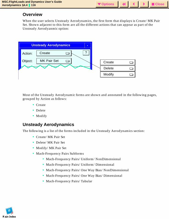
CloseOptionsMSC.FlightLoads and Dynamics User’s GuideAerodynamics §4.4 116 Options
OverviewWhen the user selects Unsteady Aerodynamics, the first form that displays is Create/MK Pair Set. Shown adjacent to this form are all the different actions that can appear as part of the Unsteady Aerodyanmic option:
Most of the Unsteady Aerodynamic forms are shown and annotated in the following pages, grouped by Action as follows:
• Create
• Delete
• Modify
Unsteady AerodynamicsThe following is a list of the forms included in the Unsteady Aerodynamics section:
• Create/MK Pair Set
• Delete/MK Pair Set
• Modify/MK Pair Set
• Mach-Frequency Pairs Subforms
• Mach-Frequency Pairs/Uniform/NonDimensional
• Mach-Frequency Pairs/Uniform/Dimensional
• Mach-Frequency Pairs/One Way Bias/NonDimensional
• Mach-Frequency Pairs/One Way Bias/Dimensional
• Mach-Frequency Pairs/Tabular
Unsteady Aerodynamics
Action:
Delete
?
Existing MK Pair Sets
Object:
Create
MK Pair Set Create
Modify
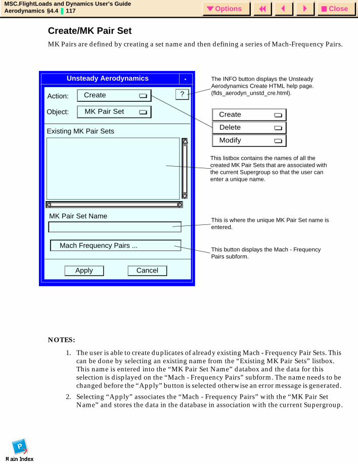
CloseOptionsMSC.FlightLoads and Dynamics User’s GuideAerodynamics §4.4 117 Options
Create/MK Pair SetMK Pairs are defined by creating a set name and then defining a series of Mach-Frequency Pairs.
NOTES:
1. The user is able to create duplicates of already existing Mach - Frequency Pair Sets. This can be done by selecting an existing name from the “Existing MK Pair Sets” listbox. This name is entered into the “MK Pair Set Name” databox and the data for this selection is displayed on the “Mach - Frequency Pairs” subform. The name needs to be changed before the “Apply” button is selected otherwise an error message is generated.
2. Selecting “Apply” associates the “Mach - Frequency Pairs” with the “MK Pair Set Name” and stores the data in the database in association with the current Supergroup.
Unsteady Aerodynamics
Action:
Delete
?
MK Pair Set Name
Existing MK Pair Sets
Mach Frequency Pairs ...
CancelApply
Object:
Create
MK Pair Set Create
Modify
This is where the unique MK Pair Set name is entered.
The INFO button displays the Unsteady Aerodynamics Create HTML help page. (flds_aerodyn_unstd_cre.html).
This listbox contains the names of all the created MK Pair Sets that are associated with the current Supergroup so that the user can enter a unique name.
This button displays the Mach - Frequency Pairs subform.
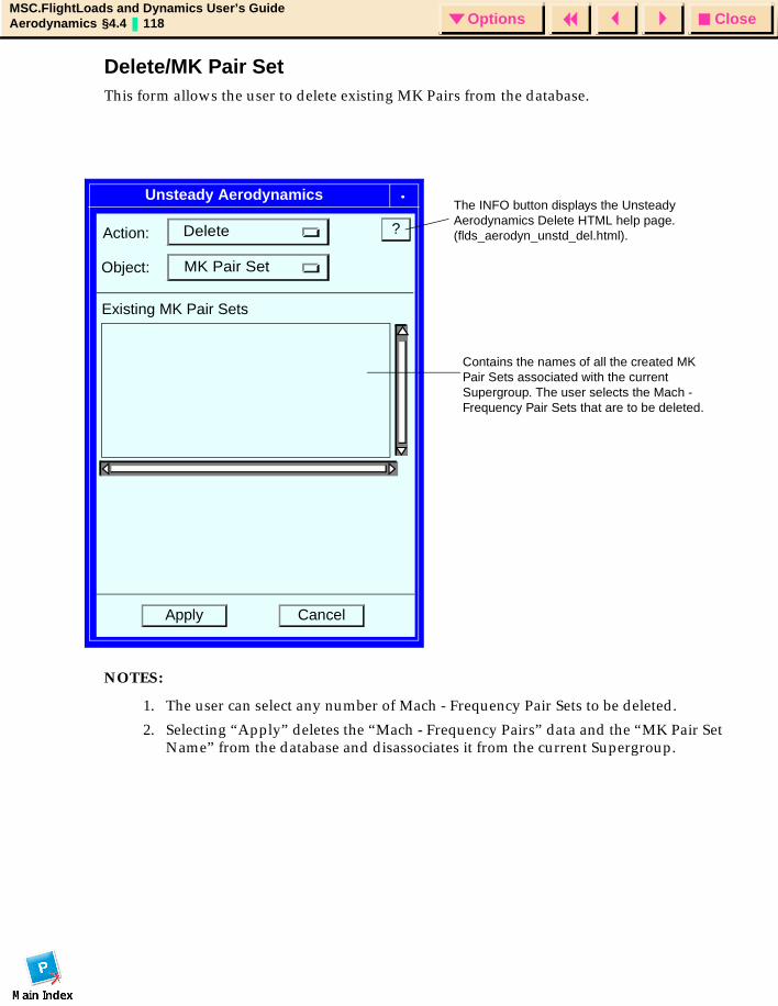
CloseOptionsMSC.FlightLoads and Dynamics User’s GuideAerodynamics §4.4 118 Options
Delete/MK Pair SetThis form allows the user to delete existing MK Pairs from the database.
NOTES:
1. The user can select any number of Mach - Frequency Pair Sets to be deleted.
2. Selecting “Apply” deletes the “Mach - Frequency Pairs” data and the “MK Pair Set Name” from the database and disassociates it from the current Supergroup.
Unsteady Aerodynamics
Action: ?
Existing MK Pair Sets
CancelApply
Object:
Delete
MK Pair Set
Contains the names of all the created MK Pair Sets associated with the current Supergroup. The user selects the Mach - Frequency Pair Sets that are to be deleted.
The INFO button displays the Unsteady Aerodynamics Delete HTML help page. (flds_aerodyn_unstd_del.html).
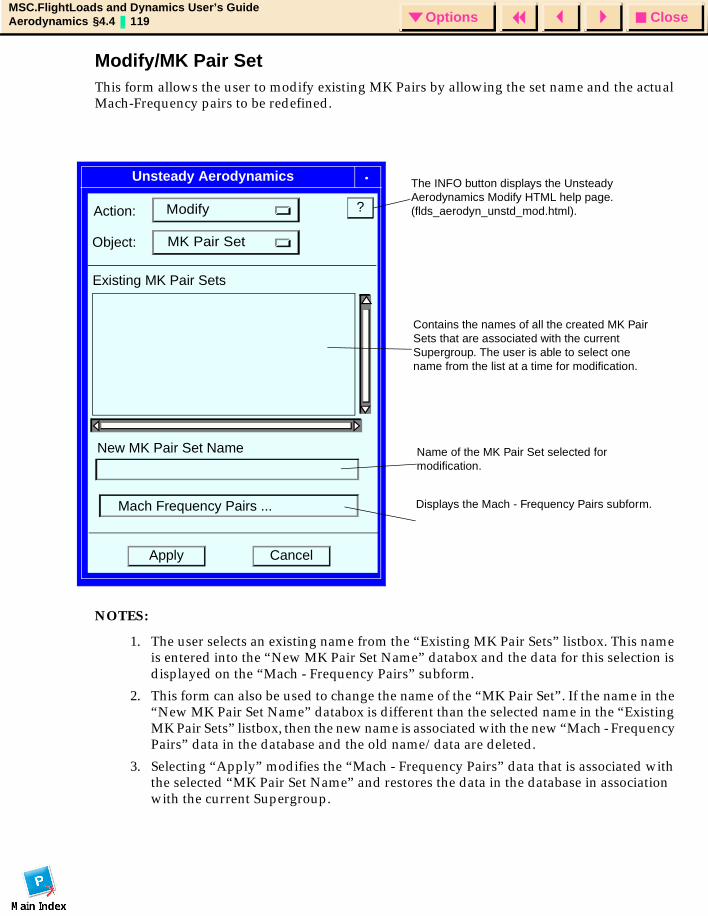
CloseOptionsMSC.FlightLoads and Dynamics User’s GuideAerodynamics §4.4 119 Options
Modify/MK Pair SetThis form allows the user to modify existing MK Pairs by allowing the set name and the actual Mach-Frequency pairs to be redefined.
NOTES:
1. The user selects an existing name from the “Existing MK Pair Sets” listbox. This name is entered into the “New MK Pair Set Name” databox and the data for this selection is displayed on the “Mach - Frequency Pairs” subform.
2. This form can also be used to change the name of the “MK Pair Set”. If the name in the “New MK Pair Set Name” databox is different than the selected name in the “Existing MK Pair Sets” listbox, then the new name is associated with the new “Mach - Frequency Pairs” data in the database and the old name/data are deleted.
3. Selecting “Apply” modifies the “Mach - Frequency Pairs” data that is associated with the selected “MK Pair Set Name” and restores the data in the database in association with the current Supergroup.
Unsteady Aerodynamics
Action: ?
New MK Pair Set Name
Existing MK Pair Sets
Mach Frequency Pairs ...
CancelApply
Object:
Modify
MK Pair Set
Contains the names of all the created MK Pair Sets that are associated with the current Supergroup. The user is able to select one name from the list at a time for modification.
Name of the MK Pair Set selected for modification.
Displays the Mach - Frequency Pairs subform.
The INFO button displays the Unsteady Aerodynamics Modify HTML help page. (flds_aerodyn_unstd_mod.html).
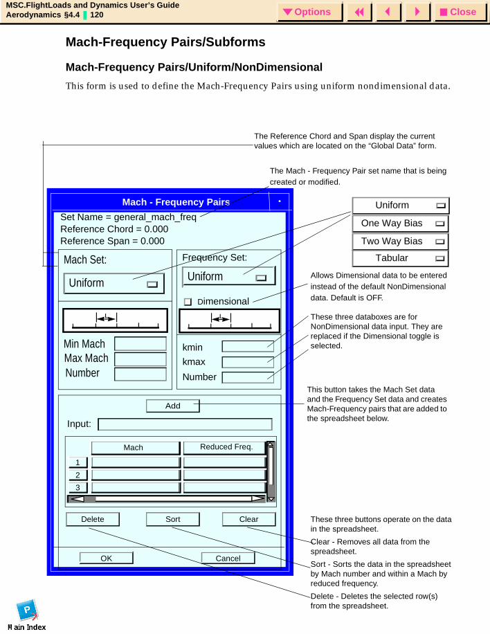
CloseOptionsMSC.FlightLoads and Dynamics User’s GuideAerodynamics §4.4 120 Options
Mach-Frequency Pairs/Subforms
Mach-Frequency Pairs/Uniform/NonDimensional
This form is used to define the Mach-Frequency Pairs using uniform nondimensional data.
Mach - Frequency Pairs
Mach Set:
Uniform
Frequency Set:
Uniform
Dimensional
Min Mach
Number
kmin
kmax
Number
Add
Input:
3
2
1
Mach
Reduced Freq.
Delete Sort Clear
OK Cancel
Uniform
One Way Bias
Two Way Bias
Tabular
Reference Chord = 0.000Reference Span = 0.000
Set Name = general_mach_freq
The Reference Chord and Span display the current values which are located on the “Global Data” form.
The Mach - Frequency Pair set name that is being created or modified.
Allows Dimensional data to be entered instead of the default NonDimensional data. Default is OFF.
These three databoxes are for NonDimensional data input. They are replaced if the Dimensional toggle is selected.
These three buttons operate on the data in the spreadsheet.
Clear - Removes all data from the spreadsheet.
Sort - Sorts the data in the spreadsheet by Mach number and within a Mach by reduced frequency.
Delete - Deletes the selected row(s) from the spreadsheet.
This button takes the Mach Set data and the Frequency Set data and creates Mach-Frequency pairs that are added to the spreadsheet below.
Max Mach
L L

CloseOptionsMSC.FlightLoads and Dynamics User’s GuideAerodynamics §4.4 121 Options
NOTES:
1. This form is valid for both the Create action and the Modify action. If an existing MK Pair Set is selected, then the data associated with that Mach - Frequency Pair is displayed in the spreadsheet. If this is a modify action, these data can be modified.
2. This form should not be displayed if the “Reference Chord” and the “Reference Span” widgets on the “Global Data” form have not already been defined. A message to direct the user should be issued.
3. M = Mach, k = Reduced Frequency, F = Cyclic Frequency, and V = Velocity.
4. The “Min Mach”, “Max Mach”, “kmin”, and “kmax” databoxes are all of type Real and blank by default.
5. The two “Number” databoxes are both of type Integer and are blank by default.
6. The spreadsheet has 20 rows to start. When the “Add” button is selected, the data entered above is transferred into the spreadsheet below any rows that are already filled in. If there are not enough rows in the spreadsheet to hold the new data the “Add” button causes new rows to be created.
7. When the “OK” button is selected, all the information that is currently in the spreadsheet is stored in the database. This data is to be stored in the same way that the “Trim Parameter” data for the “Static Aeroelasticity” solution type is currently being stored.
8. The “Mach Set” option menu and the “Frequency Set” option menu work independent of one another so they do not have to be set to the same values.
9. If only 1M or 1k is desired Min or Max Uniform with 1 should be allowed.
10. Must have at least 1 Mk pair at the time the OK button is selected.
11. The data from this form is used with the MKAERO1 card.
12. The user should be able to cycle the Mach set and Freq. Set and press the “Add” button multiple times - thereby accumulating pairs.
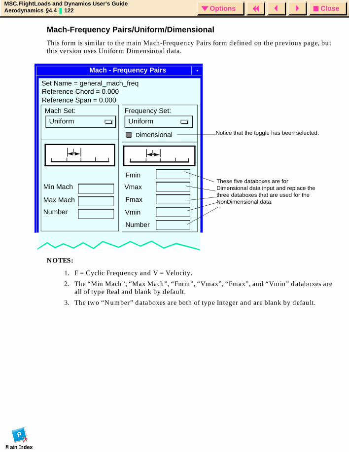
CloseOptionsMSC.FlightLoads and Dynamics User’s GuideAerodynamics §4.4 122 Options
Mach-Frequency Pairs/Uniform/Dimensional
This form is similar to the main Mach-Frequency Pairs form defined on the previous page, but this version uses Uniform Dimensional data.
NOTES:
1. F = Cyclic Frequency and V = Velocity.
2. The “Min Mach”, “Max Mach”, “Fmin”, “Vmax”, “Fmax”, and “Vmin” databoxes are all of type Real and blank by default.
3. The two “Number” databoxes are both of type Integer and are blank by default.
Mach - Frequency Pairs
Mach Set:
Uniform
Frequency Set:
Uniform
Dimensional
Fmin
Fmax
Number
Reference Chord = 0.000Reference Span = 0.000
Min Mach
Number
Max Mach
Set Name = general_mach_freq
Notice that the toggle has been selected.
These five databoxes are for Dimensional data input and replace the three databoxes that are used for the NonDimensional data.
L L
Vmin
Vmax
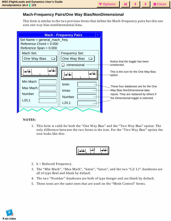
CloseOptionsMSC.FlightLoads and Dynamics User’s GuideAerodynamics §4.4 123 Options
Mach-Frequency Pairs/One Way Bias/NonDimensional
This form is similar to the two previous forms that define the Mach-Frequency pairs but this one uses one way bias nondimensional data.
NOTES:
1. This form is valid for both the “One Way Bias” and the “Two Way Bias” option. The only difference between the two forms is the icon. For the “Two Way Bias” option the icon looks like this:
2. k = Reduced Frequency.
3. The “Min Mach”, “Max Mach”, “kmin”, “kmax”, and the two “L2/L1” databoxes are all of type Real and blank by default.
4. The two “Number” databoxes are both of type Integer and are blank by default.
5. These icons are the same ones that are used on the “Mesh Control” forms.
Mach - Frequency Pairs
Mach Set:
One Way Bias
Frequency Set:
One Way Bias
Dimensional
kmax
L2/L1
kmin
Number
Reference Chord = 0.000Reference Span = 0.000
Min Mach
Number
Max Mach
L2/L1
L1 L2L1 L2
Set Name = general_mach_freq
Notice that the toggle has been unselected.
This is the icon for the One Way Bias option.
These four databoxes are for the One Way Bias NonDimensional data inputs. They are replaced by others if the Dimensional toggle is selected.
L1 L2 L1
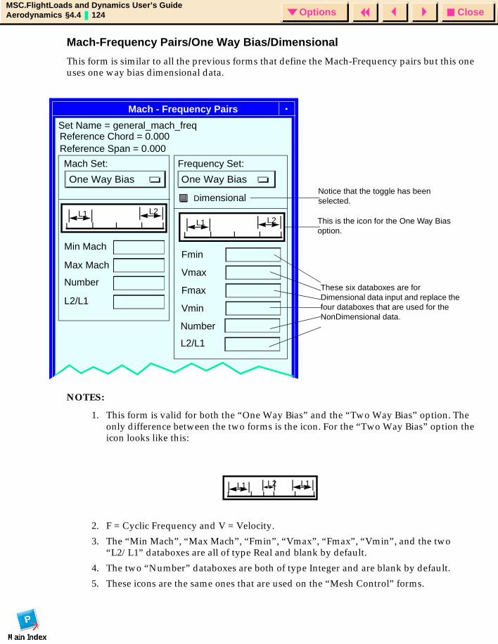
CloseOptionsMSC.FlightLoads and Dynamics User’s GuideAerodynamics §4.4 124 Options
Mach-Frequency Pairs/One Way Bias/Dimensional
This form is similar to all the previous forms that define the Mach-Frequency pairs but this one uses one way bias dimensional data.
NOTES:
1. This form is valid for both the “One Way Bias” and the “Two Way Bias” option. The only difference between the two forms is the icon. For the “Two Way Bias” option the icon looks like this:
2. F = Cyclic Frequency and V = Velocity.
3. The “Min Mach”, “Max Mach”, “Fmin”, “Vmax”, “Fmax”, “Vmin”, and the two “L2/L1” databoxes are all of type Real and blank by default.
4. The two “Number” databoxes are both of type Integer and are blank by default.
5. These icons are the same ones that are used on the “Mesh Control” forms.
Mach - Frequency Pairs
Mach Set:
One Way Bias
Frequency Set:
One Way Bias
Dimensional
Vmax
L2/L1
Fmin
Number
Reference Chord = 0.000Reference Span = 0.000
Min Mach
Number
Max Mach
L2/L1
L1 L2L1 L2
Vmin
Fmax
Set Name = general_mach_freq
Notice that the toggle has been selected.
This is the icon for the One Way Bias option.
These six databoxes are for Dimensional data input and replace the four databoxes that are used for the NonDimensional data.
L1 L2 L1
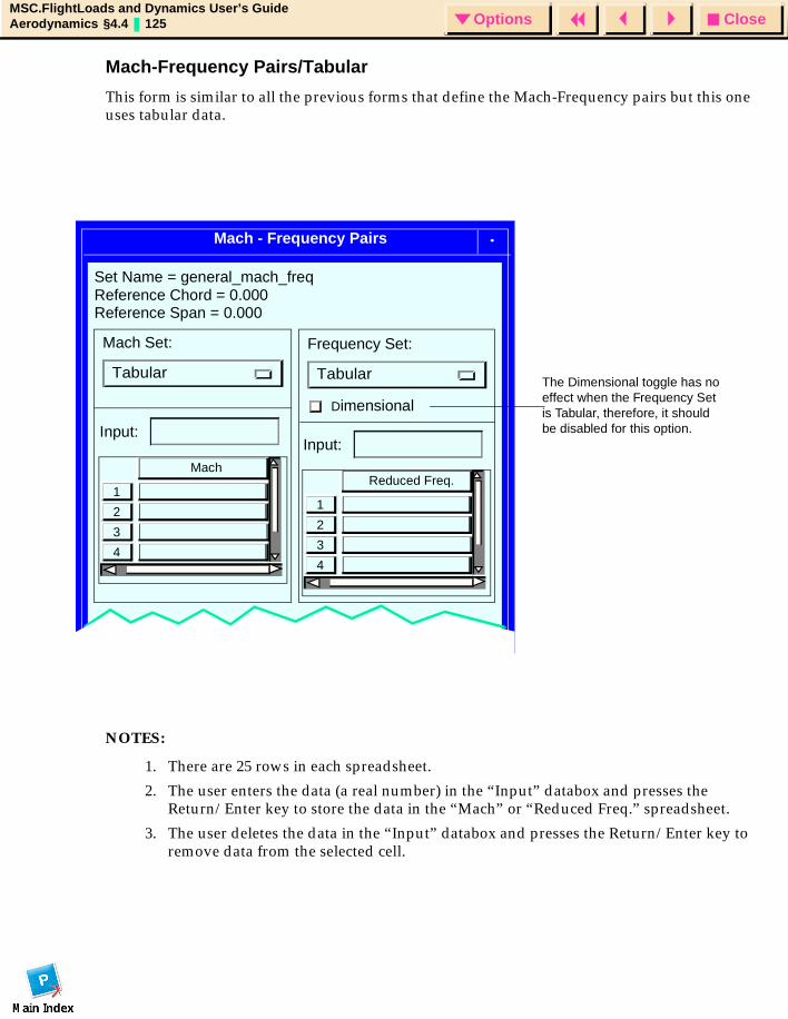
CloseOptionsMSC.FlightLoads and Dynamics User’s GuideAerodynamics §4.4 125 Options
Mach-Frequency Pairs/Tabular
This form is similar to all the previous forms that define the Mach-Frequency pairs but this one uses tabular data.
NOTES:
1. There are 25 rows in each spreadsheet.
2. The user enters the data (a real number) in the “Input” databox and presses the Return/Enter key to store the data in the “Mach” or “Reduced Freq.” spreadsheet.
3. The user deletes the data in the “Input” databox and presses the Return/Enter key to remove data from the selected cell.
Mach - Frequency Pairs
Mach Set:
Tabular
Frequency Set:
Tabular
Dimensional
3
4
2
1
Mach
Input:
3
4
2
1
Reduced Freq.
Input:
Set Name = general_mach_freq
The Dimensional toggle has no effect when the Frequency Set is Tabular, therefore, it should be disabled for this option.
Reference Chord = 0.000Reference Span = 0.000

CloseOptionsMSC.FlightLoads and Dynamics User’s GuideAerodynamics §4.4 126 Options

CloseOptionsMSC.FlightLoads and Dynamics User’s GuideAeroelasticity § 127 Options
MSC.FlightLoads and Dynamics User’s Guide
CHAPTER
5 Aeroelasticity
Introduction
Aero-Structure Coupling
Structural Monitor Points
Aeroelastic Model
Analysis
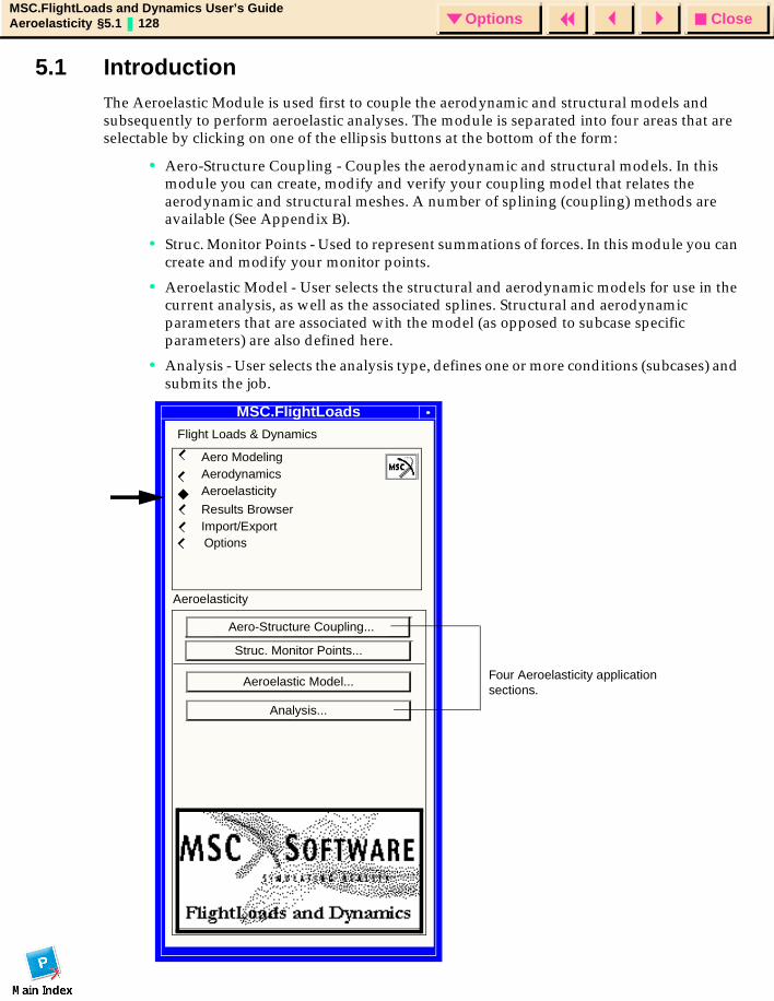
CloseOptionsMSC.FlightLoads and Dynamics User’s GuideAeroelasticity §5.1 128 Options
5.1 IntroductionThe Aeroelastic Module is used first to couple the aerodynamic and structural models and subsequently to perform aeroelastic analyses. The module is separated into four areas that are selectable by clicking on one of the ellipsis buttons at the bottom of the form:
• Aero-Structure Coupling - Couples the aerodynamic and structural models. In this module you can create, modify and verify your coupling model that relates the aerodynamic and structural meshes. A number of splining (coupling) methods are available (See Appendix B).
• Struc. Monitor Points - Used to represent summations of forces. In this module you can create and modify your monitor points.
• Aeroelastic Model - User selects the structural and aerodynamic models for use in the current analysis, as well as the associated splines. Structural and aerodynamic parameters that are associated with the model (as opposed to subcase specific parameters) are also defined here.
• Analysis - User selects the analysis type, defines one or more conditions (subcases) and submits the job.
MSC.FL&DSMSC.FlightLoads
Flight Loads & Dynamics
Aero ModelingAerodynamicsAeroelasticity
Results BrowserImport/Export
Struc. Monitor Points...
Aeroelastic Model...
Analysis...
Options
Aero-Structure Coupling...
Aeroelasticity
Four Aeroelasticity application sections.
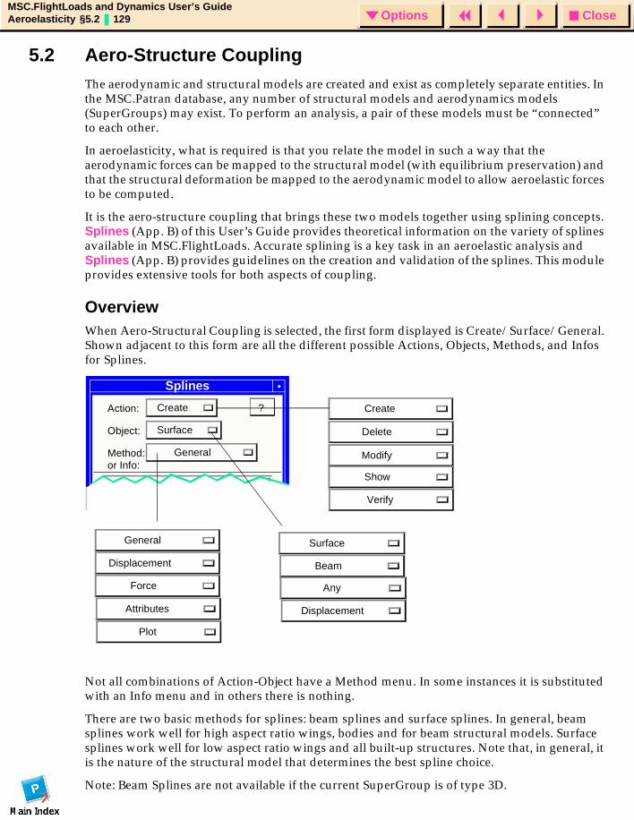
CloseOptionsMSC.FlightLoads and Dynamics User’s GuideAeroelasticity §5.2 129 Options
5.2 Aero-Structure CouplingThe aerodynamic and structural models are created and exist as completely separate entities. In the MSC.Patran database, any number of structural models and aerodynamics models (SuperGroups) may exist. To perform an analysis, a pair of these models must be “connected” to each other.
In aeroelasticity, what is required is that you relate the model in such a way that the aerodynamic forces can be mapped to the structural model (with equilibrium preservation) and that the structural deformation be mapped to the aerodynamic model to allow aeroelastic forces to be computed.
It is the aero-structure coupling that brings these two models together using splining concepts. Splines (App. B) of this User’s Guide provides theoretical information on the variety of splines available in MSC.FlightLoads. Accurate splining is a key task in an aeroelastic analysis and Splines (App. B) provides guidelines on the creation and validation of the splines. This module provides extensive tools for both aspects of coupling.
OverviewWhen Aero-Structural Coupling is selected, the first form displayed is Create/Surface/General. Shown adjacent to this form are all the different possible Actions, Objects, Methods, and Infos for Splines.
Not all combinations of Action-Object have a Method menu. In some instances it is substituted with an Info menu and in others there is nothing.
There are two basic methods for splines: beam splines and surface splines. In general, beam splines work well for high aspect ratio wings, bodies and for beam structural models. Surface splines work well for low aspect ratio wings and all built-up structures. Note that, in general, it is the nature of the structural model that determines the best spline choice.
Note: Beam Splines are not available if the current SuperGroup is of type 3D.
Splines
Action: Create
Object: Surface
Method: General
Existing Splines...
? Create
Delete
Modify
Show
Surface
Beam
General
Displacement
Force
Attributes
Any
Displacement
Verify
Plot
or Info:
CloseOptionsMSC.FlightLoads and Dynamics User’s GuideAeroelasticity §5.2 130 Options
Most of the Aero-Structural Coupling forms are shown and annotated in the following pages, grouped by Action as follows:
• Create
• Delete
• Modify
• Show
• Verify
Definitions for Spline Methods
The possible Methods are: "Displacement" which is used to transfer structural displacements to the aero model, "Force" which is used to transfer aerodynamic forces to the structural model and "General" where in the same structure and aero points are used to construct both the displacement and force transfer mechanism. In this latter case, which is the most commonly used method in MSC.Nastran, the matrix used to spline forces is simply the transpose of the matrix used to spline displacements. Users may, however, want to separate the spline usage because of the desire to map aerodynamic forces only to structural load pick up points (i.e., aircraft wing spar/rib intersections) while a larger set of structural points would more accurately define a displacement shape to be mapped to the aerodynamic model. Using this separate approach may actually increase solution efficiency due to the (potentially) reduced spline matrix densities.
Aero-Structure CouplingFollowing is a list of the Aeroelastic forms and subforms related to Aero-Structure Coupling (Splines):
• Create/Surface (General, Displacement, or Force)
• Create/Surface Subforms
• Existing Splines
• Select Groups
• Select Surface
• Optional Data
• Create/Beam (General, Displacement, or Force) Aero Body
• Create/Beam (General, Displacement, or Force) Aero Surface
• Create/Beam Subforms
• Select Body
• Select Surface
• Optional Data
• Delete (Any, Surface, or Beam)
• Modify/Surface (General, Displacement, or Force)
• Modify/Beam (General, Displacement, or Force)
• Show/Surface or Beam/Attributes
• Show Attribute Information
• Verify/Displacement/Plot
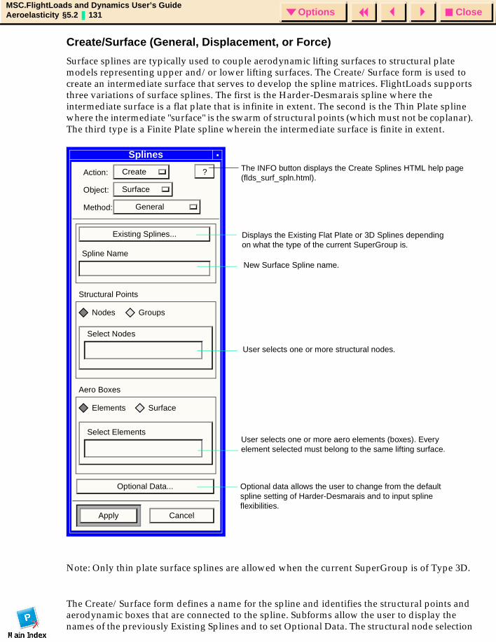
CloseOptionsMSC.FlightLoads and Dynamics User’s GuideAeroelasticity §5.2 131 Options
Create/Surface (General, Displacement, or Force)
Surface splines are typically used to couple aerodynamic lifting surfaces to structural plate models representing upper and/or lower lifting surfaces. The Create/Surface form is used to create an intermediate surface that serves to develop the spline matrices. FlightLoads supports three variations of surface splines. The first is the Harder-Desmarais spline where the intermediate surface is a flat plate that is infinite in extent. The second is the Thin Plate spline where the intermediate "surface" is the swarm of structural points (which must not be coplanar). The third type is a Finite Plate spline wherein the intermediate surface is finite in extent.
Note: Only thin plate surface splines are allowed when the current SuperGroup is of Type 3D.
The Create/Surface form defines a name for the spline and identifies the structural points and aerodynamic boxes that are connected to the spline. Subforms allow the user to display the names of the previously Existing Splines and to set Optional Data. The structural node selection
Splines
Action: Create
Object: Surface
Method: General
Existing Splines...
Spline Name
Structural Points
Nodes Groups
Select Nodes
Aero Boxes
Elements Surface
Select Elements
Optional Data...
Apply Cancel
?
New Surface Spline name.
Displays the Existing Flat Plate or 3D Splines depending on what the type of the current SuperGroup is.
User selects one or more structural nodes.
User selects one or more aero elements (boxes). Every element selected must belong to the same lifting surface.
Optional data allows the user to change from the default spline setting of Harder-Desmarais and to input spline flexibilities.
The INFO button displays the Create Splines HTML help page (flds_surf_spln.html).
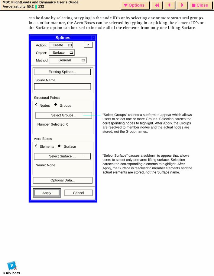
CloseOptionsMSC.FlightLoads and Dynamics User’s GuideAeroelasticity §5.2 132 Options
can be done by selecting or typing in the node ID’s or by selecting one or more structural groups. In a similar manner, the Aero Boxes can be selected by typing in or picking the element ID’s or the Surface option can be used to include all of the elements from only one Lifting Surface.
Splines
Action: Create
Object: Surface
Method: General
Existing Splines...
Spline Name
Structural Points
Nodes Groups
Aero Boxes
Elements Surface
Optional Data...
Apply Cancel
?
Select Groups...
Select Surface ...
Number Selected: 0
Name: None
“Select Groups” causes a subform to appear which allows users to select one or more Groups. Selection causes the corresponding nodes to highlight. After Apply, the Groups are resolved to member nodes and the actual nodes are stored, not the Group names.
“Select Surface” causes a subform to appear that allows users to select only one aero lifting surface. Selection causes the corresponding elements to highlight. After Apply, the Surface is resolved to member elements and the actual elements are stored, not the Surface name.
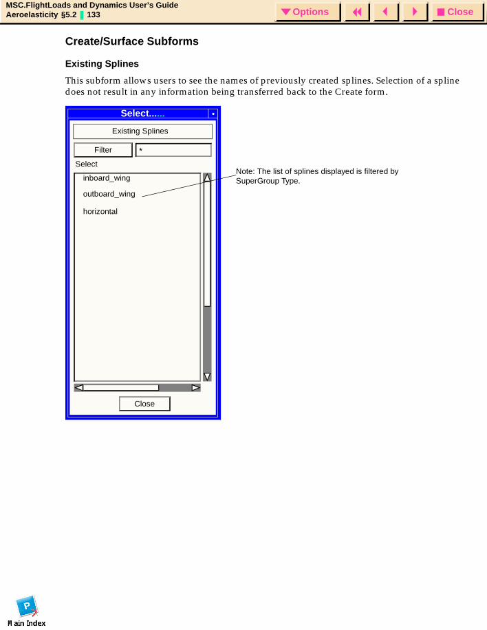
CloseOptionsMSC.FlightLoads and Dynamics User’s GuideAeroelasticity §5.2 133 Options
Create/Surface Subforms
Existing Splines
This subform allows users to see the names of previously created splines. Selection of a spline does not result in any information being transferred back to the Create form.
Select......
Existing Splines
inboard_wing
outboard_wing
Filter *
Close
horizontal
SelectNote: The list of splines displayed is filtered by SuperGroup Type.
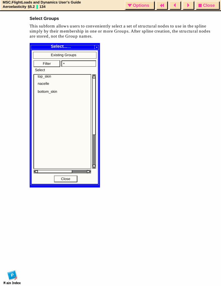
CloseOptionsMSC.FlightLoads and Dynamics User’s GuideAeroelasticity §5.2 134 Options
Select Groups
This subform allows users to conveniently select a set of structural nodes to use in the spline simply by their membership in one or more Groups. After spline creation, the structural nodes are stored, not the Group names.
Existing Groups
top_skin
nacelle
Filter *
Close
bottom_skin
Select
Select......
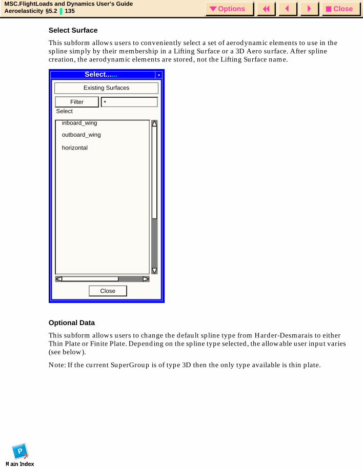
CloseOptionsMSC.FlightLoads and Dynamics User’s GuideAeroelasticity §5.2 135 Options
Select Surface
This subform allows users to conveniently select a set of aerodynamic elements to use in the spline simply by their membership in a Lifting Surface or a 3D Aero surface. After spline creation, the aerodynamic elements are stored, not the Lifting Surface name.
Optional Data
This subform allows users to change the default spline type from Harder-Desmarais to either Thin Plate or Finite Plate. Depending on the spline type selected, the allowable user input varies (see below).
Note: If the current SuperGroup is of type 3D then the only type available is thin plate.
Select...
Existing Surfaces
inboard_wing
outboard_wing
Filter *
Close
horizontal
Select
Select......
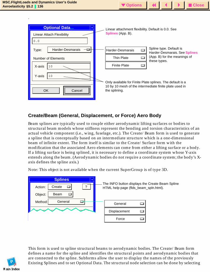
CloseOptionsMSC.FlightLoads and Dynamics User’s GuideAeroelasticity §5.2 136 Options
.
Create/Beam (General, Displacement, or Force) Aero Body
Beam splines are typically used to couple either aerodynamic lifting surfaces or bodies to structural beam models whose stiffness represent the bending and torsion characteristics of an actual vehicle component (i.e., wing, fuselage, etc.). The Create/Beam form is used to generate a spline that is conceptually based on an intermediate structure which is a one-dimensional beam of infinite extent. The form itself is similar to the Create/Surface form with the modification that the associated Aero elements can come from either a lifting surface or a body. If a lifting surface is being splined, it is necessary to define a coordinate system whose Y-axis extends along the beam. (Aerodynamic bodies do not require a coordinate system; the body’s X-axis defines the spline axis.)
Note: This object is not available when the current SuperGroup is of type 3D.
This form is used to spline structural beams to aerodynamic bodies. The Create/Beam form defines a name for the spline and identifies the structural points and aerodynamic bodies that are connected to the spline. Subforms allow the user to display the names of the previously Existing Splines and to set Optional Data. The structural node selection can be done by selecting
Otional Data
Linear Attach Flexibility
0.0
Type: Harder-Desmarais
Number of Elements
X-axis 10
Y-axis 10
OK Cancel
Harder-Desmarais
Thin Plate
Finite Plate
Linear attachment flexibility. Default is 0.0. See Splines (App. B).
Only available for Finite Plate splines. The default is a 10 by 10 mesh of the intermediate finite plate used in the splining.
Spline type. Default is Harder-Desmarais. See Splines (App. B) for the meanings of these types.
Optional Data...
Splines
Action: Create
Object: Beam
Method: General
Existing Splines...
?
General
Displacement
Force
The INFO button displays the Create Beam Spline HTML help page (flds_beam_spln.html).
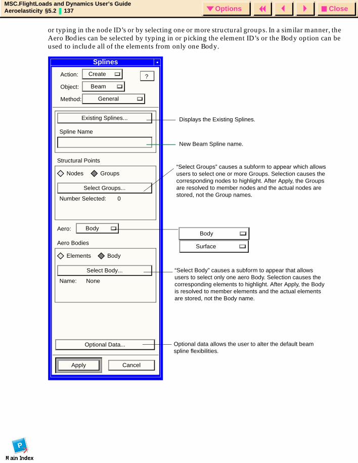
CloseOptionsMSC.FlightLoads and Dynamics User’s GuideAeroelasticity §5.2 137 Options
or typing in the node ID’s or by selecting one or more structural groups. In a similar manner, the Aero Bodies can be selected by typing in or picking the element ID’s or the Body option can be used to include all of the elements from only one Body.
Splines
Action: Create
Object: Beam
Method: General
Existing Splines...
Spline Name
Structural Points
Nodes Groups
Select Groups...
Number Selected: 0
Aero: Body
Aero Bodies
Elements Body
Select Body...
Name: None
Optional Data...
Apply Cancel
?
Body
Surface
New Beam Spline name.
Displays the Existing Splines.
“Select Groups” causes a subform to appear which allows users to select one or more Groups. Selection causes the corresponding nodes to highlight. After Apply, the Groups are resolved to member nodes and the actual nodes are stored, not the Group names.
“Select Body” causes a subform to appear that allows users to select only one aero Body. Selection causes the corresponding elements to highlight. After Apply, the Body is resolved to member elements and the actual elements are stored, not the Body name.
Optional data allows the user to alter the default beam spline flexibilities.
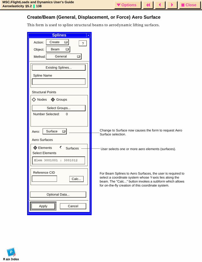
CloseOptionsMSC.FlightLoads and Dynamics User’s GuideAeroelasticity §5.2 138 Options
Create/Beam (General, Displacement, or Force) Aero Surface
This form is used to spline structural beams to aerodynamic lifting surfaces.
Splines
Action: Create
Object: Beam
Method: General
Existing Splines...
Spline Name
Structural Points
Nodes Groups
Select Groups...
Number Selected: 0
Aero: Surface
Aero Surfaces
?
User selects one or more aero elements (surfaces).
Change to Surface now causes the form to request Aero Surface selection.
Elements SurfacesSelect Elements
Elem 3001001 : 3001012
Reference CID For Beam Splines to Aero Surfaces, the user is required to select a coordinate system whose Y-axis lies along the beam. The "Calc..." button invokes a subform which allows for on-the-fly creation of this coordinate system.
Optional Data...
Apply Cancel
Calc...
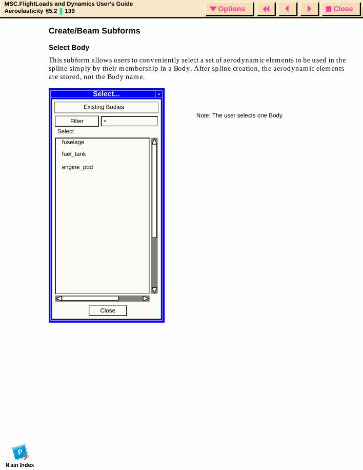
CloseOptionsMSC.FlightLoads and Dynamics User’s GuideAeroelasticity §5.2 139 Options
Create/Beam Subforms
Select Body
This subform allows users to conveniently select a set of aerodynamic elements to be used in the spline simply by their membership in a Body. After spline creation, the aerodynamic elements are stored, not the Body name.
Select...
Existing Bodies
fuselage
fuel_tank
Filter *
Close
engine_pod
Note: The user selects one Body.
Select

CloseOptionsMSC.FlightLoads and Dynamics User’s GuideAeroelasticity §5.2 140 Options
Select Surface
This subform allows users to conveniently select a set of aerodynamic elements to be used in the spline simply by their membership in a Lifting Surface. After spline creation, the aerodynamic elements are stored, not the Lifting Surface name.
Select...
Existing Surfaces
inboard_wing
outboard_wing
Filter *
Close
horizontal
Note: The user selects one Surface.
Select
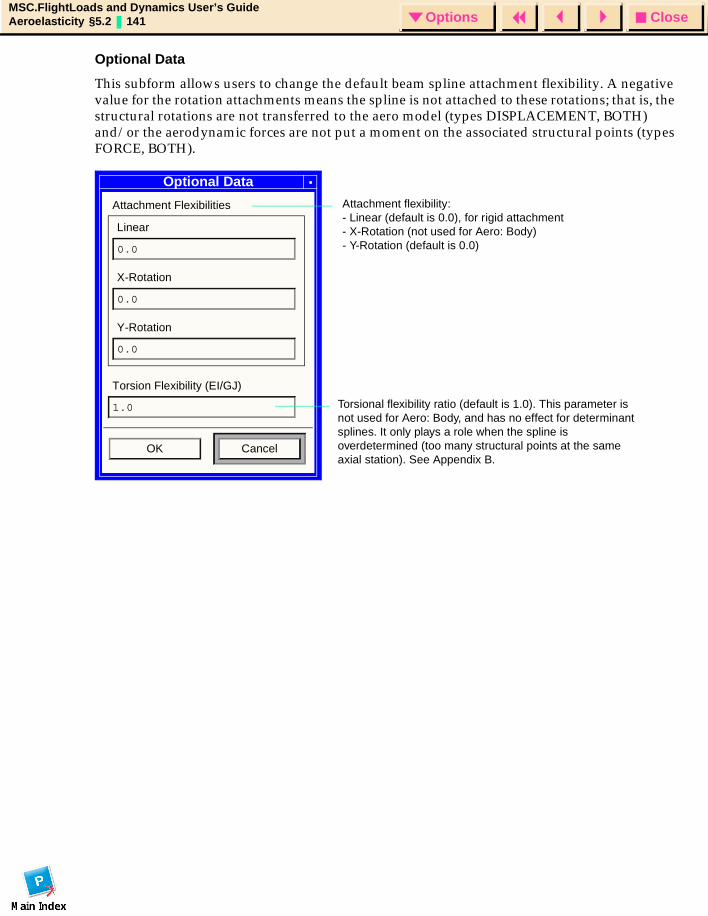
CloseOptionsMSC.FlightLoads and Dynamics User’s GuideAeroelasticity §5.2 141 Options
Optional Data
This subform allows users to change the default beam spline attachment flexibility. A negative value for the rotation attachments means the spline is not attached to these rotations; that is, the structural rotations are not transferred to the aero model (types DISPLACEMENT, BOTH) and/or the aerodynamic forces are not put a moment on the associated structural points (types FORCE, BOTH).
Attachment flexibility: - Linear (default is 0.0), for rigid attachment- X-Rotation (not used for Aero: Body)- Y-Rotation (default is 0.0)
Torsional flexibility ratio (default is 1.0). This parameter is not used for Aero: Body, and has no effect for determinant splines. It only plays a role when the spline is overdetermined (too many structural points at the same axial station). See Appendix B.
Optional Data
Attachment Flexibilities
Linear
0.0
X-Rotation
0.0
Y-Rotation
0.0
Torsion Flexibility (EI/GJ)
1.0
OK Cancel
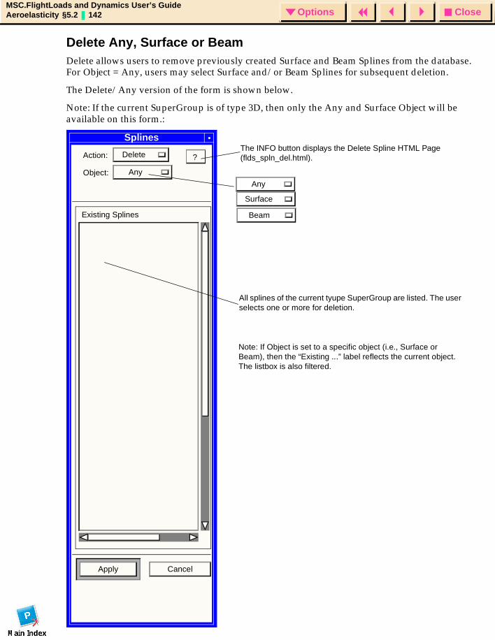
CloseOptionsMSC.FlightLoads and Dynamics User’s GuideAeroelasticity §5.2 142 Options
Delete Any, Surface or BeamDelete allows users to remove previously created Surface and Beam Splines from the database. For Object = Any, users may select Surface and/or Beam Splines for subsequent deletion.
The Delete/Any version of the form is shown below.
Note: If the current SuperGroup is of type 3D, then only the Any and Surface Object will be available on this form.:
Splines
Action: Delete
Object: Any
Existing Splines
Apply Cancel
?
All splines of the current tyupe SuperGroup are listed. The user selects one or more for deletion.
Note: If Object is set to a specific object (i.e., Surface or Beam), then the “Existing ...” label reflects the current object. The listbox is also filtered.
The INFO button displays the Delete Spline HTML Page (flds_spln_del.html).
Any
Surface
Beam
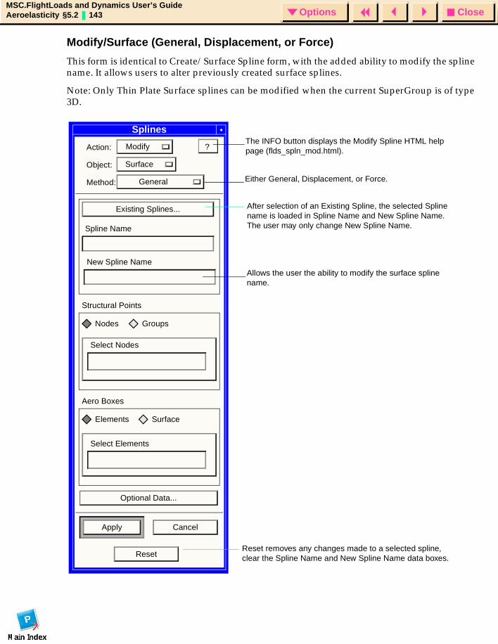
CloseOptionsMSC.FlightLoads and Dynamics User’s GuideAeroelasticity §5.2 143 Options
Modify/Surface (General, Displacement, or Force)
This form is identical to Create/Surface Spline form, with the added ability to modify the spline name. It allows users to alter previously created surface splines.
Note: Only Thin Plate Surface splines can be modified when the current SuperGroup is of type 3D.
Splines
Action: Modify
Object: Surface
Method: General
Existing Splines...
Spline Name
Structural Points
Nodes Groups
Select Nodes
Aero Boxes
Elements Surface
Select Elements
Optional Data...
Apply Cancel
?
After selection of an Existing Spline, the selected Spline name is loaded in Spline Name and New Spline Name. The user may only change New Spline Name.
New Spline Name
ResetReset removes any changes made to a selected spline, clear the Spline Name and New Spline Name data boxes.
The INFO button displays the Modify Spline HTML help page (flds_spln_mod.html).
Either General, Displacement, or Force.
Allows the user the ability to modify the surface spline name.
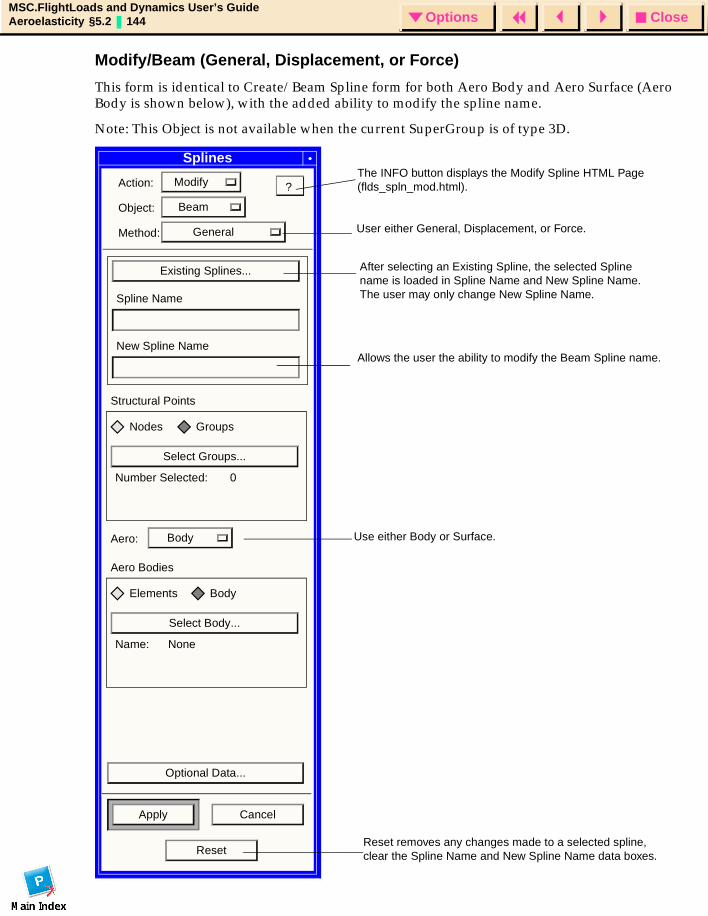
CloseOptionsMSC.FlightLoads and Dynamics User’s GuideAeroelasticity §5.2 144 Options
Modify/Beam (General, Displacement, or Force)
This form is identical to Create/Beam Spline form for both Aero Body and Aero Surface (Aero Body is shown below), with the added ability to modify the spline name.
Note: This Object is not available when the current SuperGroup is of type 3D.
Splines
Action: Modify
Object: Beam
Method: General
Existing Splines...
Spline Name
Structural Points
Nodes Groups
Select Groups...
Number Selected: 0
Aero: Body
Aero Bodies
Elements Body
Select Body...
Name: None
Optional Data...
Apply Cancel
?
After selecting an Existing Spline, the selected Spline name is loaded in Spline Name and New Spline Name. The user may only change New Spline Name.
Reset removes any changes made to a selected spline, clear the Spline Name and New Spline Name data boxes.
New Spline Name
Reset
The INFO button displays the Modify Spline HTML Page (flds_spln_mod.html).
User either General, Displacement, or Force.
Allows the user the ability to modify the Beam Spline name.
Use either Body or Surface.
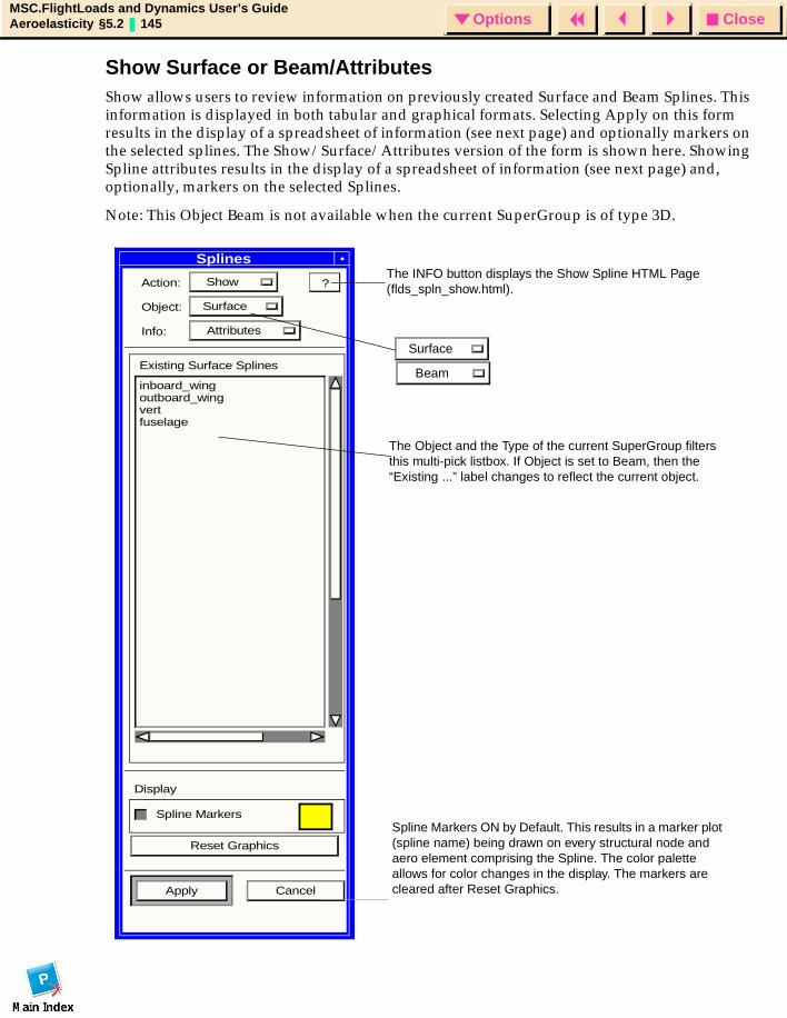
CloseOptionsMSC.FlightLoads and Dynamics User’s GuideAeroelasticity §5.2 145 Options
Show Surface or Beam/AttributesShow allows users to review information on previously created Surface and Beam Splines. This information is displayed in both tabular and graphical formats. Selecting Apply on this form results in the display of a spreadsheet of information (see next page) and optionally markers on the selected splines. The Show/Surface/Attributes version of the form is shown here. Showing Spline attributes results in the display of a spreadsheet of information (see next page) and, optionally, markers on the selected Splines.
Note: This Object Beam is not available when the current SuperGroup is of type 3D.
Action: Show
Object: Surface
Info: Attributes
Existing Surface Splines
inboard_wingoutboard_wingvertfuselage
Display
Spline Markers
Reset Graphics
Apply Cancel
?
The Object and the Type of the current SuperGroup filters this multi-pick listbox. If Object is set to Beam, then the “Existing ...” label changes to reflect the current object.
Spline Markers ON by Default. This results in a marker plot (spline name) being drawn on every structural node and aero element comprising the Spline. The color palette allows for color changes in the display. The markers are cleared after Reset Graphics.
SplinesThe INFO button displays the Show Spline HTML Page (flds_spln_show.html).
Beam
Surface
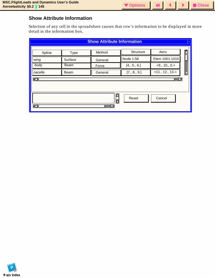
CloseOptionsMSC.FlightLoads and Dynamics User’s GuideAeroelasticity §5.2 146 Options
Show Attribute Information
Selection of any cell in the spreadsheet causes that row’s information to be displayed in more detail in the information box.
Show Attribute Information
Spline Type
wing Surface
Structure Aero
Node 1:58 Elem 1001:1010
body Beam
nacelle Beam
[4., 5., 6.] <9., 10., 0.>
[7., 8., 9.] <11., 12., 13.>
CancelReset
Method
General
Force
General
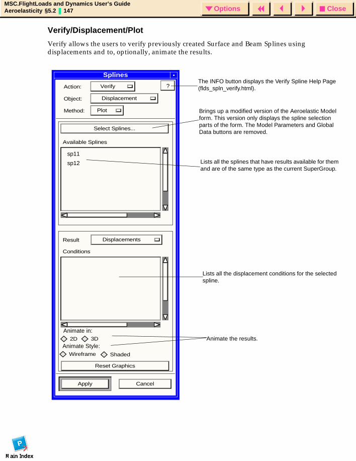
CloseOptionsMSC.FlightLoads and Dynamics User’s GuideAeroelasticity §5.2 147 Options
Verify/Displacement/Plot
Verify allows the users to verify previously created Surface and Beam Splines using displacements and to, optionally, animate the results.
Splines
Action: Verify
Object: Displacement
Method: Plot
Select Splines...
Available Splines
Result Displacements
Conditions
Wireframe Shaded
Reset Graphics
Apply Cancel
?
sp11
sp12
The INFO button displays the Verify Spline Help Page (flds_spln_verify.html).
Brings up a modified version of the Aeroelastic Model form. This version only displays the spline selection parts of the form. The Model Parameters and Global Data buttons are removed.
Lists all the splines that have results available for them and are of the same type as the current SuperGroup.
Lists all the displacement conditions for the selected spline.
Animate the results.Animate Style:
2D 3D
Animate in:
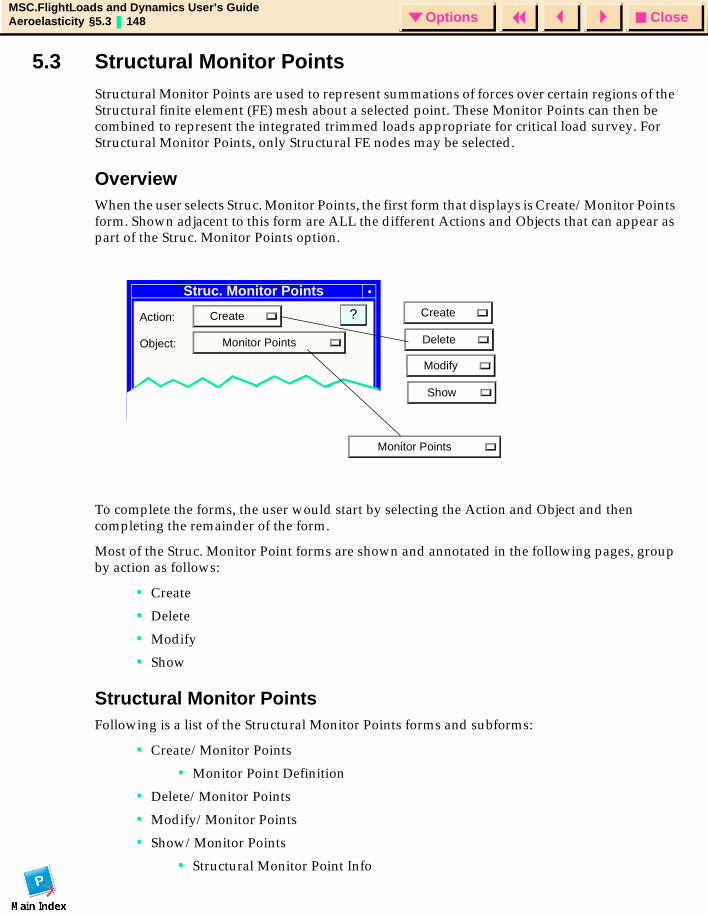
CloseOptionsMSC.FlightLoads and Dynamics User’s GuideAeroelasticity §5.3 148 Options
5.3 Structural Monitor PointsStructural Monitor Points are used to represent summations of forces over certain regions of the Structural finite element (FE) mesh about a selected point. These Monitor Points can then be combined to represent the integrated trimmed loads appropriate for critical load survey. For Structural Monitor Points, only Structural FE nodes may be selected.
OverviewWhen the user selects Struc. Monitor Points, the first form that displays is Create/Monitor Points form. Shown adjacent to this form are ALL the different Actions and Objects that can appear as part of the Struc. Monitor Points option.
To complete the forms, the user would start by selecting the Action and Object and then completing the remainder of the form.
Most of the Struc. Monitor Point forms are shown and annotated in the following pages, group by action as follows:
• Create
• Delete
• Modify
• Show
Structural Monitor PointsFollowing is a list of the Structural Monitor Points forms and subforms:
• Create/Monitor Points
• Monitor Point Definition
• Delete/Monitor Points
• Modify/Monitor Points
• Show/Monitor Points
• Structural Monitor Point Info
Struc. Monitor Points
Action: Create
Object: Monitor Points
?
Existing Monitor Points
Monitor Points
Create
Delete
Modify
Show
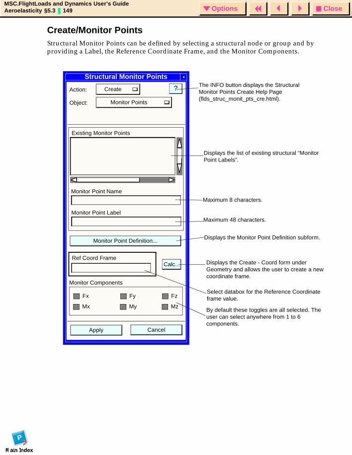
CloseOptionsMSC.FlightLoads and Dynamics User’s GuideAeroelasticity §5.3 149 Options
Create/Monitor PointsStructural Monitor Points can be defined by selecting a structural node or group and by providing a Label, the Reference Coordinate Frame, and the Monitor Components.
Structural Monitor Points
Action: Create
Object: Monitor Points
?
Monitor Point Definition...
CancelApply
Ref Coord Frame
Existing Monitor Points
Monitor Point Label
Monitor Point Name
Calc...
Monitor Components
Fx
Mx
Fz
Mz
Fy
My
Displays the list of existing structural “Monitor Point Labels”.
Maximum 8 characters.
Maximum 48 characters.
Displays the Monitor Point Definition subform.
Displays the Create - Coord form under Geometry and allows the user to create a new coordinate frame.
Select databox for the Reference Coordinate frame value.
By default these toggles are all selected. The user can select anywhere from 1 to 6 components.
The INFO button displays the Structural Monitor Points Create Help Page (flds_struc_monit_pts_cre.html).
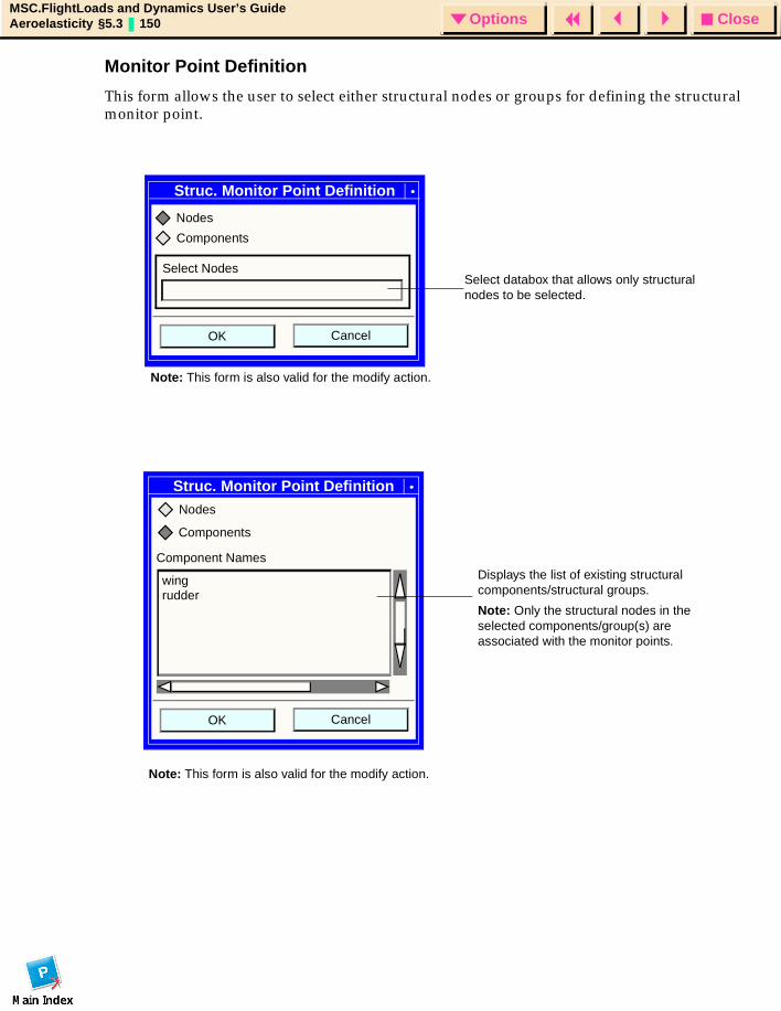
CloseOptionsMSC.FlightLoads and Dynamics User’s GuideAeroelasticity §5.3 150 Options
Monitor Point Definition
This form allows the user to select either structural nodes or groups for defining the structural monitor point.
Struc. Monitor Point Definition
CancelOK
Components
Nodes
Select NodesSelect databox that allows only structural nodes to be selected.
Note: This form is also valid for the modify action.
Struc. Monitor Point Definition
Component Names
wing
CancelOK
Nodes
Components
rudder
Displays the list of existing structural components/structural groups.
Note: Only the structural nodes in the selected components/group(s) are associated with the monitor points.
Note: This form is also valid for the modify action.
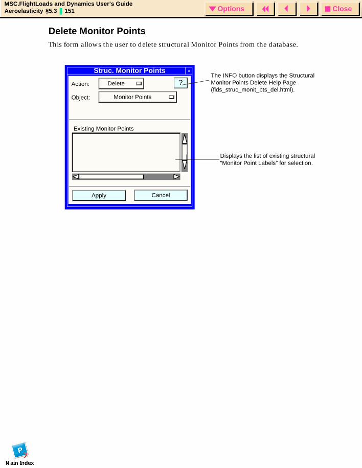
CloseOptionsMSC.FlightLoads and Dynamics User’s GuideAeroelasticity §5.3 151 Options
Delete Monitor PointsThis form allows the user to delete structural Monitor Points from the database.
Struc. Monitor Points
Action: Delete
Object: Monitor Points
?
CancelApply
Existing Monitor Points
Displays the list of existing structural “Monitor Point Labels” for selection.
The INFO button displays the Structural Monitor Points Delete Help Page (flds_struc_monit_pts_del.html).
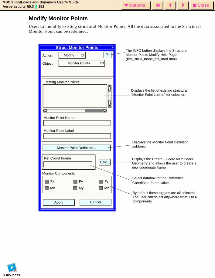
CloseOptionsMSC.FlightLoads and Dynamics User’s GuideAeroelasticity §5.3 152 Options
Modify Monitor PointsUsers can modify existing structural Monitor Points. All the data associated to the Structural Monitor Point can be redefined.
Struc. Monitor Points
Action: Modify
Object: Monitor Points
?
Monitor Point Definition...
CancelApply
Ref Coord Frame
Existing Monitor Points
Monitor Point Label
Monitor Point Name
Calc...
Monitor Components
Fx
Mx
Fz
Mz
Fy
My
Displays the list of existing structural “Monitor Point Labels” for selection.
Displays the Monitor Point Definition subform.
Displays the Create - Coord form under Geometry and allows the user to create a new coordinate frame.
Select databox for the Reference Coordinate frame value.
By default these toggles are all selected. The user can select anywhere from 1 to 6 components.
The INFO button displays the Structural Monitor Points Modify Help Page (flds_struc_monit_pts_mod.html).
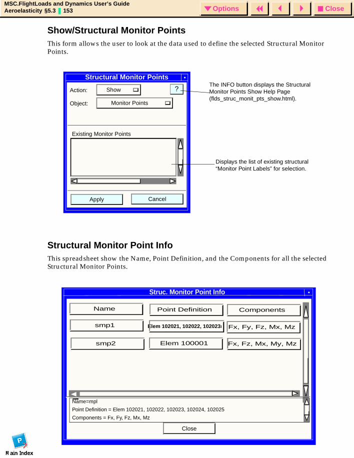
CloseOptionsMSC.FlightLoads and Dynamics User’s GuideAeroelasticity §5.3 153 Options
Show/Structural Monitor PointsThis form allows the user to look at the data used to define the selected Structural Monitor Points.
Structural Monitor Point InfoThis spreadsheet show the Name, Point Definition, and the Components for all the selected Structural Monitor Points.
Structural Monitor Points
Action: Show
Object: Monitor Points
?
CancelApply
Existing Monitor Points
Displays the list of existing structural “Monitor Point Labels” for selection.
The INFO button displays the Structural Monitor Points Show Help Page (flds_struc_monit_pts_show.html).
Struc. Monitor Point Info
Close
Name=mpl
Point Definition = Elem 102021, 102022, 102023, 102024, 102025
Components = Fx, Fy, Fz, Mx, Mz
Point Definition
Elem 102021, 102022, 102023l
Elem 100001 Fx, Fz, Mx, My, Mz
Fx, Fy, Fz, Mx, Mz
Components
smp1
Name
smp2
CloseOptionsMSC.FlightLoads and Dynamics User’s GuideAeroelasticity §5.4 154 Options
5.4 Aeroelastic ModelAeroelasticity, as the name implies, is the coupling of aerodynamics and structures. Prior to performing an aeroelastic analysis with MSC.FlightLoads and Dynamics, an aeroelastic model must be identified. This model is comprised of a structures model (of necessity, one that is appropriate for dynamics analysis -- it should include appropriate inertias and produce good normal modes), an aerodynamic model, and the splines that couple the two models. FlightLoads was designed to support the evolution (maturation) of aero and structural models. Multiple representations of the structure and the aerodynamic meshes may appear in a single database for subsequent use in aeroelastic analyses. It is also appropriate at this point in the simulation process to define the model-dependent parameter data pertaining to structural and aerodynamic model behaviors.
Following is a list of the Aeroelastic Model form and its subforms:
• Aeroelastic Model
• Aeroelastic Model Subforms
• Select Aero Model
• Select Structural Model
• Model Parameters
• Global Data
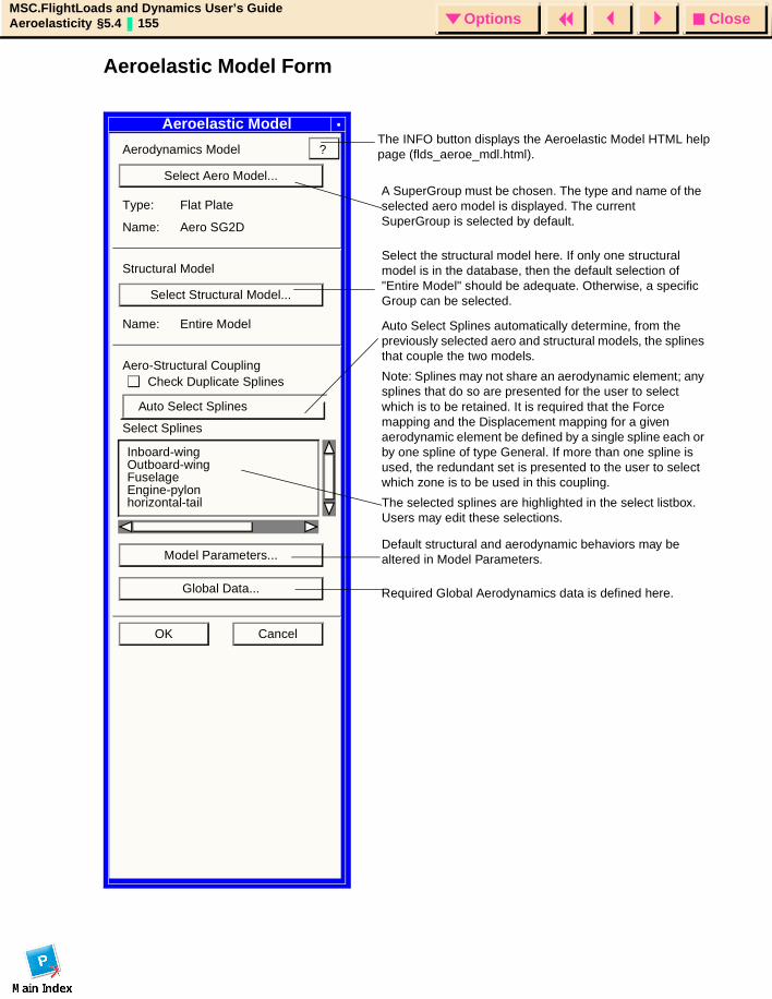
CloseOptionsMSC.FlightLoads and Dynamics User’s GuideAeroelasticity §5.4 155 Options
Aeroelastic Model Form
Aeroelastic Model
Aerodynamics Model
Select Aero Model...
Type: Flat Plate
Name: Aero SG2D
Structural Model
Select Structural Model...
Name: Entire Model
Aero-Structural Coupling
Select Splines
Model Parameters...
Global Data...
OK Cancel
?
A SuperGroup must be chosen. The type and name of the selected aero model is displayed. The current SuperGroup is selected by default.
Select the structural model here. If only one structural model is in the database, then the default selection of "Entire Model" should be adequate. Otherwise, a specific Group can be selected.
Auto Select Splines automatically determine, from the previously selected aero and structural models, the splines that couple the two models.
Note: Splines may not share an aerodynamic element; any splines that do so are presented for the user to select which is to be retained. It is required that the Force mapping and the Displacement mapping for a given aerodynamic element be defined by a single spline each or by one spline of type General. If more than one spline is used, the redundant set is presented to the user to select which zone is to be used in this coupling.
The selected splines are highlighted in the select listbox. Users may edit these selections.
Inboard-wingOutboard-wingFuselageEngine-pylonhorizontal-tail
Default structural and aerodynamic behaviors may be altered in Model Parameters.
Required Global Aerodynamics data is defined here.
The INFO button displays the Aeroelastic Model HTML help page (flds_aeroe_mdl.html).
Auto Select Splines
Check Duplicate Splines
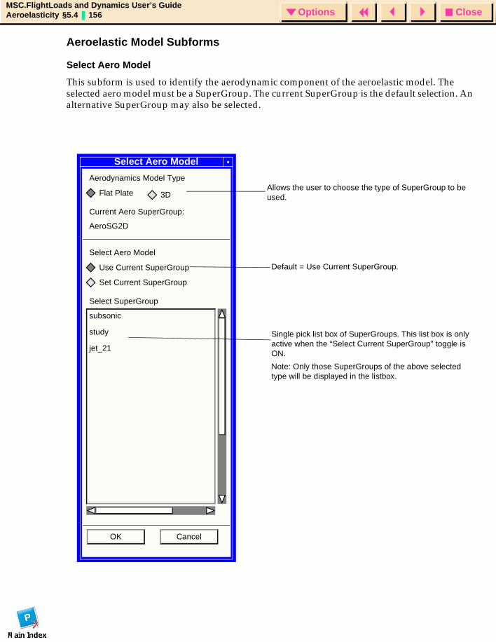
CloseOptionsMSC.FlightLoads and Dynamics User’s GuideAeroelasticity §5.4 156 Options
Aeroelastic Model Subforms
Select Aero Model
This subform is used to identify the aerodynamic component of the aeroelastic model. The selected aero model must be a SuperGroup. The current SuperGroup is the default selection. An alternative SuperGroup may also be selected.
Select Aero Model
Aerodynamics Model Type
Flat Plate
Current Aero SuperGroup:
AeroSG2D
Select Aero Model
Use Current SuperGroup
Set Current SuperGroup
Select SuperGroup
subsonic
OK Cancel
Default = Use Current SuperGroup.
Single pick list box of SuperGroups. This list box is only active when the “Select Current SuperGroup” toggle is ON.
Note: Only those SuperGroups of the above selected type will be displayed in the listbox.
study
jet_21
Allows the user to choose the type of SuperGroup to be used.3D
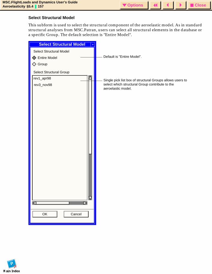
CloseOptionsMSC.FlightLoads and Dynamics User’s GuideAeroelasticity §5.4 157 Options
Select Structural Model
This subform is used to select the structural component of the aeroelastic model. As in standard structural analyses from MSC.Patran, users can select all structural elements in the database or a specific Group. The default selection is "Entire Model".
Select Structural Model
Select Structural Model
Entire Model
Group
Select Structural Group
rev1_apr98
OK Cancel
Default is "Entire Model".
Single pick list box of structural Groups allows users to select which structural Group contribute to the aeroelastic model.
rev3_nov98
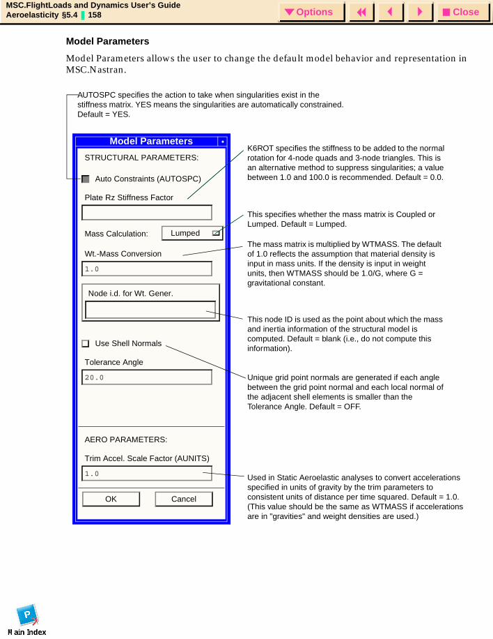
CloseOptionsMSC.FlightLoads and Dynamics User’s GuideAeroelasticity §5.4 158 Options
Model Parameters
Model Parameters allows the user to change the default model behavior and representation in MSC.Nastran.
Model Parameters
STRUCTURAL PARAMETERS:
Auto Constraints (AUTOSPC)
Plate Rz Stiffness Factor
Mass Calculation: Lumped
Wt.-Mass Conversion
1.0
Node i.d. for Wt. Gener.
Use Shell Normals
Tolerance Angle
20.0
AERO PARAMETERS:
Trim Accel. Scale Factor (AUNITS)
1.0
OK Cancel
AUTOSPC specifies the action to take when singularities exist in the stiffness matrix. YES means the singularities are automatically constrained. Default = YES.
K6ROT specifies the stiffness to be added to the normal rotation for 4-node quads and 3-node triangles. This is an alternative method to suppress singularities; a value between 1.0 and 100.0 is recommended. Default = 0.0.
This specifies whether the mass matrix is Coupled or Lumped. Default = Lumped.
The mass matrix is multiplied by WTMASS. The default of 1.0 reflects the assumption that material density is input in mass units. If the density is input in weight units, then WTMASS should be 1.0/G, where G = gravitational constant.
This node ID is used as the point about which the mass and inertia information of the structural model is computed. Default = blank (i.e., do not compute this information).
Unique grid point normals are generated if each angle between the grid point normal and each local normal of the adjacent shell elements is smaller than the Tolerance Angle. Default = OFF.
Used in Static Aeroelastic analyses to convert accelerations specified in units of gravity by the trim parameters to consistent units of distance per time squared. Default = 1.0. (This value should be the same as WTMASS if accelerations are in "gravities" and weight densities are used.)
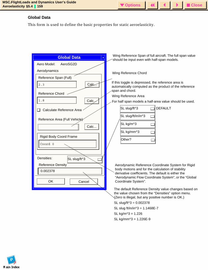
CloseOptionsMSC.FlightLoads and Dynamics User’s GuideAeroelasticity §5.4 159 Options
Global Data
This form is used to define the basic properties for static aeroelasticity.
Global Data
Aerodynamics
Reference Span (Full)
2.3 Calc...
Reference Chord
1.8
Calculate Reference Area
Reference Area (Full Vehicle)
Rigid Body Coord Frame
Coord 0
OK Cancel
Aero Model: AeroSG2D
Densities:
Other?
0.002378
Reference Density
Wing Reference Area
For half span models a half-area value should be used.
Calc...SL kg/m^3
SL slug/ft/in/in^3
SL slug/ft^3
SL kg/mm^3
SL slug/ft^3
The default Reference Density value changes based on the value chosen from the “Densities” option menu. (Zero is illegal, but any positive number is OK.)
SL slug/ft^3 = 0.002378
SL slug ft/in/in^3 = 1.1468E-7
SL kg/m^3 = 1.226
SL kg/mm^3 = 1.226E-9
DEFAULT
Wing Reference Span of full aircraft. The full span value should be input even with half-span models.
Wing Reference Chord
If this toggle is depressed, the reference area is automatically computed as the product of the reference span and chord.
Aerodynamic Reference Coordinate System for Rigid body motions and for the calculation of stability derivative coefficients. The default is either the “Aerodynamic Flow Coordinate System”, or the “Global Coordinate System”.
Calc...
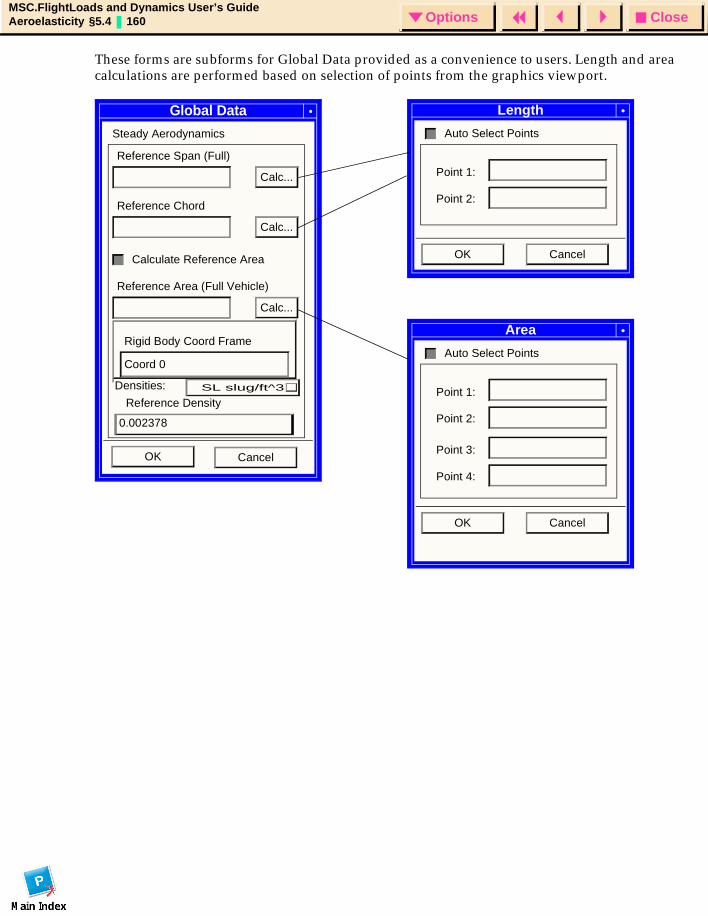
CloseOptionsMSC.FlightLoads and Dynamics User’s GuideAeroelasticity §5.4 160 Options
These forms are subforms for Global Data provided as a convenience to users. Length and area calculations are performed based on selection of points from the graphics viewport.
Global Data
Steady Aerodynamics
Reference Span (Full)
Calc...
Reference Chord
Calc...
Calculate Reference Area
Reference Area (Full Vehicle)
Calc...
Rigid Body Coord Frame
Coord 0
OK Cancel
Length
Auto Select Points
OK Cancel
Point 1:
Point 2:
Area
Auto Select Points
OK Cancel
Point 1:
Point 2:
Point 3:
Point 4:
0.002378
Reference Density
Densities: SL slug/ft^3
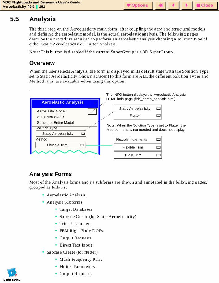
CloseOptionsMSC.FlightLoads and Dynamics User’s GuideAeroelasticity §5.5 161 Options
5.5 AnalysisThe third step on the Aeroelasticity main form, after coupling the aero and structural models and defining the aeroelastic model, is the actual aeroelastic analysis. The following pages describe the procedure required to perform an aeroelastic analysis choosing a solution type of either Static Aeroelasticity or Flutter Analysis.
Note: This button is disabled if the current SuperGroup is a 3D SuperGroup.
OverviewWhen the user selects Analysis, the form is displayed in its default state with the Solution Type set to Static Aeroelasticity. Shown adjacent to this form are ALL the different Solution Types and Methods that are available when using this option.
.
Analysis FormsMost of the Analysis forms and its subforms are shown and annotated in the following pages, grouped as follows:
• Aeroelastic Analysis
• Analysis Subforms
• Target Databases
• Subcase Create (for Static Aeroelasticity)
• Trim Parameters
• FEM Rigid Body DOFs
• Output Requests
• Direct Text Input
• Subcase Create (for flutter)
• Mach-Frequency Pairs
• Flutter Parameters
• Output Requests
Static Aeroelasticity
Method
Flexible Trim
?
Flexible Increments
Flexible Trim
Rigid Trim
The INFO button displays the Aeroelastic Analysis HTML help page (flds_aeroe_analysis.html).
Aeroelastic Analysis
Solution Type
Aeroelastic Model
Aero: AeroSG2D
Structure: Entire Model
Static Aeroelasticity
Note: When the Solution Type is set to Flutter, the Method menu is not needed and does not display.
Flutter
CloseOptionsMSC.FlightLoads and Dynamics User’s GuideAeroelasticity §5.5 162 Options
• Direct Text Input
• Select Superelements
• Real Eigenvalue
• Complex Eigenvalue
• Subcase Select
• Existing Jobs
• Job Parameters
• Analysis Manager
Aeroelastic AnalysisThe basic Aeroelastic Analysis form is the same for any of the selected Methods associated with Static Aeroelasticity. Please note that the Flexible Increment Method is not allowed to be mixed with the Rigid or Flexible Trim Method in a single analysis job. If either a Flexible Increment or Rigid/Flexible Trim Subcase is selected for analysis, the other option(s) will be disabled.
Three Methods are available with Static Aeroelasticity: Flexible Increments, Flexible Trim, and Rigid Trim:
Flexible Trim is the most common Static Aeroelastic analysis Method performed in MSC.Nastran. This is the calculation of the trim parameters (vehicle rigid body motion and control device) settings required to maintain the desired aircraft attitude, rate and/or acceleration. The result of this calculation is not only the trim parameters but also the resulting external loads on the air vehicle. These loads include the components of aerodynamics (rigid), inertia (structural mass), flexible (structural flexibility) and trim (use of control devices or rigid body motion).
Rigid Trim is identical to Flexible Trim, with the exception that structural flexibility effects are ignored. The vehicle inertial properties are obtained from the structural model, identified as part of the aeroelastic model. Note that the structural model is still elastic (it deforms); “rigid” implies that the increment in aerodynamic load induced by those deformations is ignored (no aeroelastic feedback).
Flexible Increments is the calculation of flexible load increments due to unit perturbations of each trim parameter, one at a time. These are always calculated as part of a Flexible Trim analysis. By requesting a Flexible Increment Method, the trim solver will not be invoked and the Flexible Increments may be optionally stored on the aeroelastic database. If stored, these may then be reused for rapid trim solutions as the calculations up the point of calculation of Flexible Increments is no longer required.
The Basic Flutter Analysis capability allows you to define MSC.Nastran Flutter Analysis: PK, PKNL, K, and KE.
In addition to the Flutter subcase there are forms to allow the user to select the defined hardpoint aerodynamics, Mach Number and Reduced Frequency pair, for aerodynamic database population. Note that the creation of the data and the use of the data are separate.
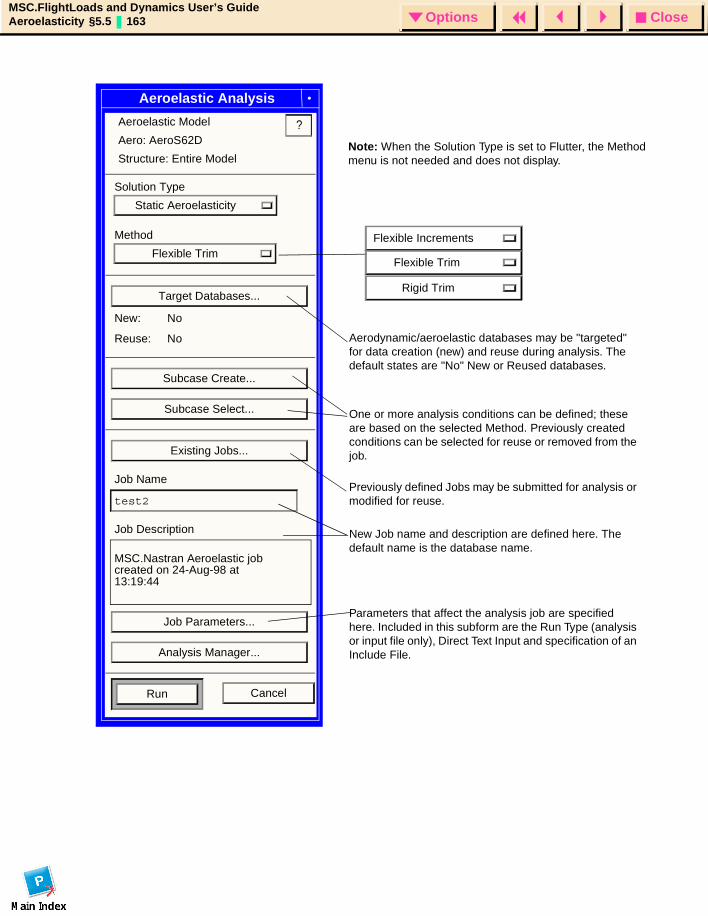
CloseOptionsMSC.FlightLoads and Dynamics User’s GuideAeroelasticity §5.5 163 Options
Solution Type
Static Aeroelasticity
Method
Flexible Trim
Target Databases...
New: No
Reuse: No
Subcase Create...
Subcase Select...
Existing Jobs...
Job Name
test2
Job Description
MSC.Nastran Aeroelastic job
Job Parameters...
Analysis Manager...
Run Cancel
?
created on 24-Aug-98 at 13:19:44
Flexible Increments
Flexible Trim
Rigid Trim
Aerodynamic/aeroelastic databases may be "targeted" for data creation (new) and reuse during analysis. The default states are "No" New or Reused databases.
One or more analysis conditions can be defined; these are based on the selected Method. Previously created conditions can be selected for reuse or removed from the job.
Previously defined Jobs may be submitted for analysis or modified for reuse.
New Job name and description are defined here. The default name is the database name.
Parameters that affect the analysis job are specified here. Included in this subform are the Run Type (analysis or input file only), Direct Text Input and specification of an Include File.
Aeroelastic Analysis
Aeroelastic Model
Aero: AeroS62D
Structure: Entire ModelNote: When the Solution Type is set to Flutter, the Method menu is not needed and does not display.

CloseOptionsMSC.FlightLoads and Dynamics User’s GuideAeroelasticity §5.5 164 Options
Target Database
MSC.FlightLoads has been designed to simplify the creation and reuse of archival collections and aerodynamic and static aeroelastic dates. This capability has been in MSC.Nastran aeroelasticity but required a very knowledgeable user to ensure the correct data were saved and significant DMAP work was needed to reuse. Now these features are automated. Appendix E and F contain a more detailed description of the contents of the two collections. The aerodynamic database contains no structural information and all the aerodynamic model geometry mesh and rigid aerodynamics that are needed for any subsequent aeroelastic analysis.
The aeroelastic database requires the aerodynamic database, and includes the aerodynamic data after it has been coupled to a particular structure. Of necessity, these data are a function of the selected dynamic pressures in addition to all the structural boundary conditions.
The aerodynamic database is useful to perform studies of a given configuration with more than one structural or spline representation. The aeroelastic database is associated with a single pair of math models, but can simulate any trimmed, quasi-static maneuver as a simple linear combination of the archival collection. It is useful to rapidly generate trimmed distributed loads for a large number of maneuvers within a given Mach and dynamic pressure (i.e., altitude and speed). Appendix C discusses the “unit solutions” or “flexible increment” that comprise this collection.
Aerodynamic or Aeroelastic databases may be created and selected for data reuse. If an Aeroelastic database is selected for reuse, its companion Aerodynamic database will be automatically selected.
Note: This form is valid for both solution types.
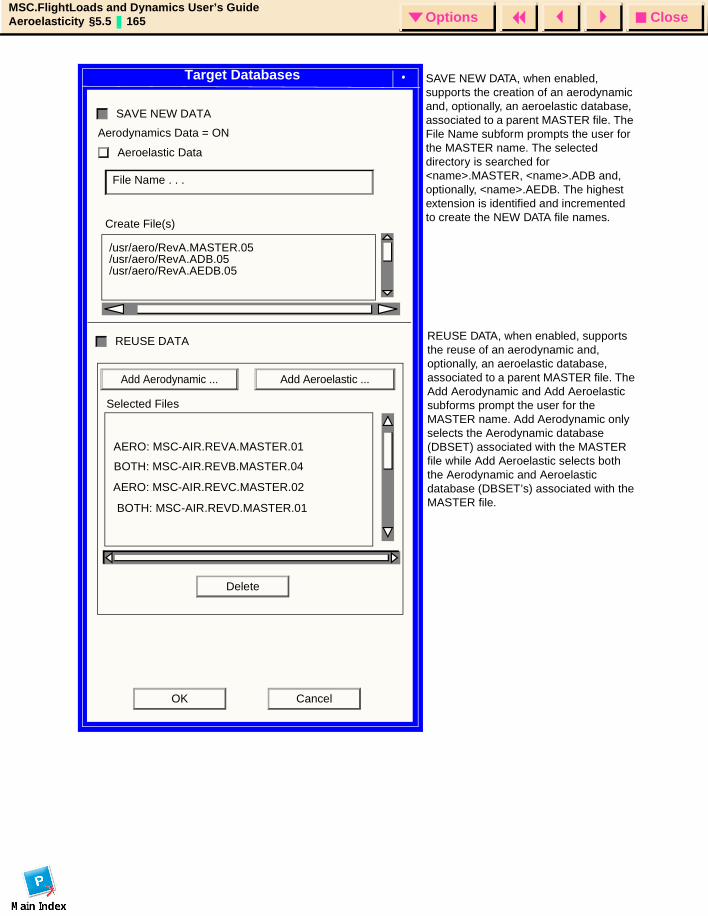
CloseOptionsMSC.FlightLoads and Dynamics User’s GuideAeroelasticity §5.5 165 Options
CancelOK
AERO: MSC-AIR.REVA.MASTER.01
Create File(s)
/usr/aero/RevA.MASTER.05
SAVE NEW DATA
Aerodynamics Data = ON
Aeroelastic Data
/usr/aero/RevA.ADB.05/usr/aero/RevA.AEDB.05
REUSE DATA
Selected Files
AERO: MSC-AIR.REVC.MASTER.02
BOTH: MSC-AIR.REVB.MASTER.04
BOTH: MSC-AIR.REVD.MASTER.01
Add Aerodynamic ... Add Aeroelastic ...
SAVE NEW DATA, when enabled, supports the creation of an aerodynamic and, optionally, an aeroelastic database, associated to a parent MASTER file. The File Name subform prompts the user for the MASTER name. The selected directory is searched for <name>.MASTER, <name>.ADB and, optionally, <name>.AEDB. The highest extension is identified and incremented to create the NEW DATA file names.
REUSE DATA, when enabled, supports the reuse of an aerodynamic and, optionally, an aeroelastic database, associated to a parent MASTER file. The Add Aerodynamic and Add Aeroelastic subforms prompt the user for the MASTER name. Add Aerodynamic only selects the Aerodynamic database (DBSET) associated with the MASTER file while Add Aeroelastic selects both the Aerodynamic and Aeroelastic database (DBSET’s) associated with the MASTER file.
File Name . . .
Delete
Target Databases
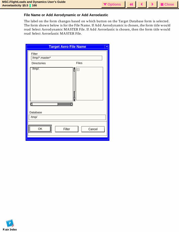
CloseOptionsMSC.FlightLoads and Dynamics User’s GuideAeroelasticity §5.5 166 Options
File Name or Add Aerodynamic or Add Aeroelastic
The label on the form changes based on which button on the Target Database form is selected. The form shown below is for the File Name. If Add Aerodynamic is chosen, the form title would read Select Aerodynamic MASTER File. If Add Aeroelastic is chosen, then the form title would read Select Aeroelastic MASTER File.
Target Aero File Name
Filter/tmp/*.master*
Directories Files
/tmp/. [ ]
/tmp/
Database
OK CancelFilter
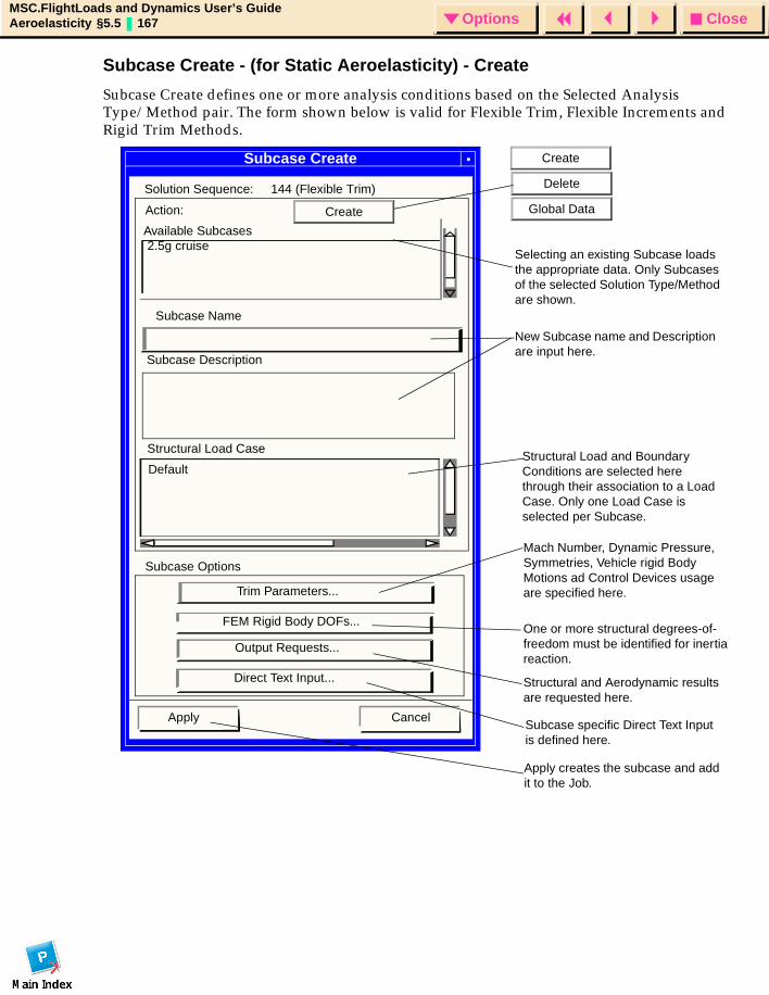
CloseOptionsMSC.FlightLoads and Dynamics User’s GuideAeroelasticity §5.5 167 Options
Subcase Create - (for Static Aeroelasticity) - Create
Subcase Create defines one or more analysis conditions based on the Selected Analysis Type/Method pair. The form shown below is valid for Flexible Trim, Flexible Increments and Rigid Trim Methods.
Subcase Create
Solution Sequence: 144 (Flexible Trim)
2.5g cruise
Subcase Name
Subcase Description
CancelApply
Default
Trim Parameters...
FEM Rigid Body DOFs...
Output Requests...
Direct Text Input...
Subcase Options
Selecting an existing Subcase loads the appropriate data. Only Subcases of the selected Solution Type/Method are shown.
New Subcase name and Description are input here.
Structural Load and Boundary Conditions are selected here through their association to a Load Case. Only one Load Case is selected per Subcase.
Structural Load Case
Mach Number, Dynamic Pressure, Symmetries, Vehicle rigid Body Motions ad Control Devices usage are specified here.
One or more structural degrees-of-freedom must be identified for inertiareaction.
Structural and Aerodynamic results are requested here.
Subcase specific Direct Text Input is defined here.
Apply creates the subcase and add it to the Job.
Available Subcases
Action: Create
Create
Delete
Global Data
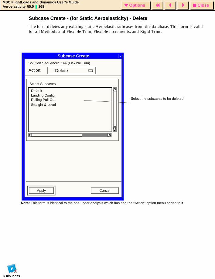
CloseOptionsMSC.FlightLoads and Dynamics User’s GuideAeroelasticity §5.5 168 Options
Subcase Create - (for Static Aeroelasticity) - Delete
The form deletes any existing static Aeroelastic subcases from the database. This form is valid for all Methods and Flexible Trim, Flexible Increments, and Rigid Trim.
Subcase Create
Solution Sequence: 144 (Flexible Trim)
Apply Cancel
Select Subcases
DeleteAction:
DefaultLanding ConfigRolling Pull-OutStraight & Level
Select the subcases to be deleted.
Note: This form is identical to the one under analysis which has had the “Action” option menu added to it.
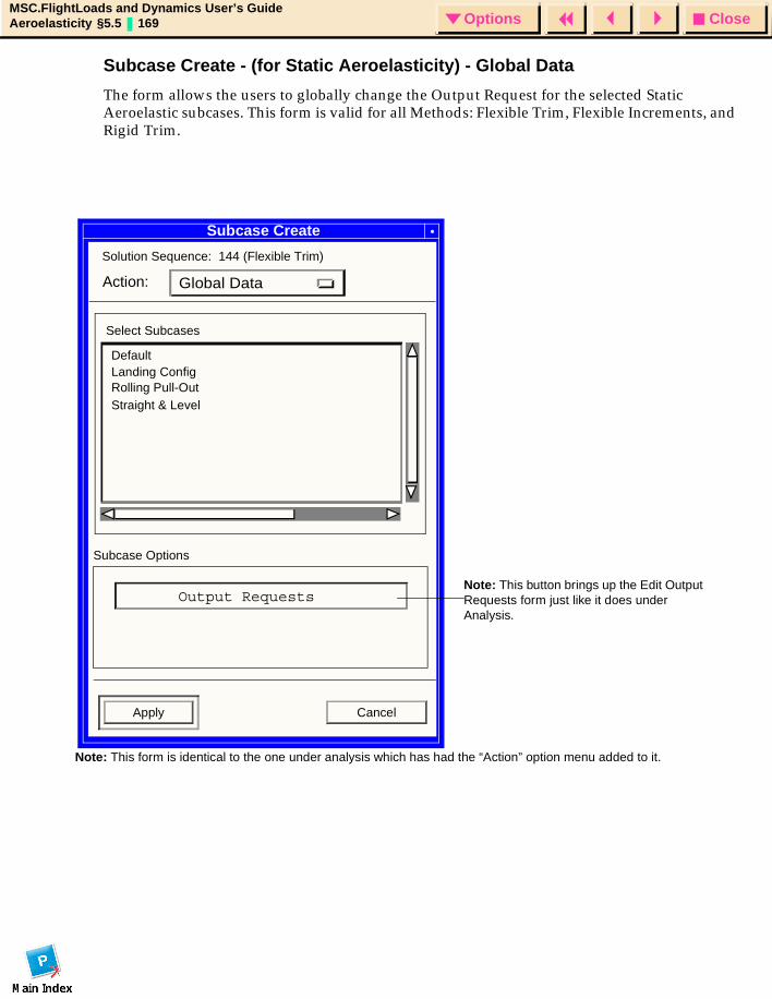
CloseOptionsMSC.FlightLoads and Dynamics User’s GuideAeroelasticity §5.5 169 Options
Subcase Create - (for Static Aeroelasticity) - Global Data
The form allows the users to globally change the Output Request for the selected Static Aeroelastic subcases. This form is valid for all Methods: Flexible Trim, Flexible Increments, and Rigid Trim.
Subcase Create
Solution Sequence: 144 (Flexible Trim)
Apply Cancel
Select Subcases
Global DataAction:
Subcase Options
Output Requests
DefaultLanding ConfigRolling Pull-OutStraight & Level
Note: This button brings up the Edit Output Requests form just like it does under Analysis.
Note: This form is identical to the one under analysis which has had the “Action” option menu added to it.
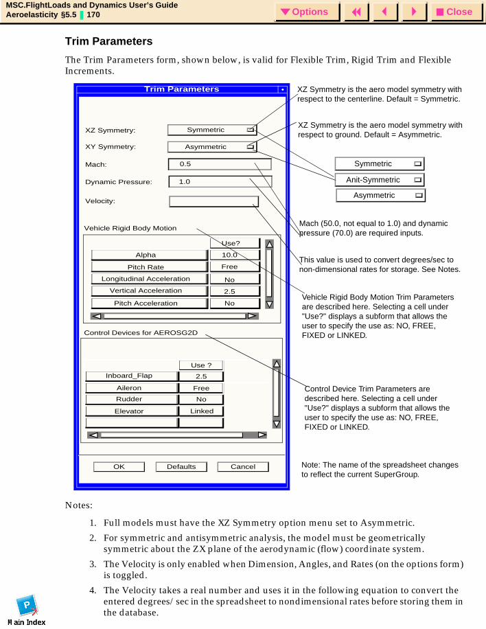
CloseOptionsMSC.FlightLoads and Dynamics User’s GuideAeroelasticity §5.5 170 Options
Trim Parameters
The Trim Parameters form, shown below, is valid for Flexible Trim, Rigid Trim and Flexible Increments.
Notes:
1. Full models must have the XZ Symmetry option menu set to Asymmetric.
2. For symmetric and antisymmetric analysis, the model must be geometrically symmetric about the ZX plane of the aerodynamic (flow) coordinate system.
3. The Velocity is only enabled when Dimension, Angles, and Rates (on the options form) is toggled.
4. The Velocity takes a real number and uses it in the following equation to convert the entered degrees/sec in the spreadsheet to nondimensional rates before storing them in the database.
Trim Parameters
XZ Symmetry: Symmetric
XY Symmetry:
Mach:
Dynamic Pressure:
Use?
Alpha
Pitch Rate
Longitudinal Acceleration
Vertical Acceleration
Pitch Acceleration
10.0
Free
Vehicle Rigid Body Motion
No
2.5
No
OK Defaults Cancel
Inboard_Flap
Aileron
Rudder
Elevator
Use ?
2.5
Free
No
Linked
Control Devices for AEROSG2D
Asymmetric
0.5
1.0
Vehicle Rigid Body Motion Trim Parameters are described here. Selecting a cell under "Use?" displays a subform that allows the user to specify the use as: NO, FREE, FIXED or LINKED.
Control Device Trim Parameters are described here. Selecting a cell under "Use?" displays a subform that allows the user to specify the use as: NO, FREE, FIXED or LINKED.
Note: The name of the spreadsheet changes to reflect the current SuperGroup.
XZ Symmetry is the aero model symmetry with respect to the centerline. Default = Symmetric.
XZ Symmetry is the aero model symmetry with respect to ground. Default = Asymmetric.
Mach (50.0, not equal to 1.0) and dynamic pressure (70.0) are required inputs.
This value is used to convert degrees/sec to non-dimensional rates for storage. See Notes.
Symmetric
Anit-Symmetric
AsymmetricVelocity:
CloseOptionsMSC.FlightLoads and Dynamics User’s GuideAeroelasticity §5.5 171 Options
.
5. The Vehicle Rigid Body Motion Trim Parameters listed on the lower half of this form, are dependent on the value of XZ Symmetry. The Symmetric parameters are: alpha (angle of attack), pitch rate, longitudinal acceleration, vertical acceleration and pitch acceleration. The Antisymmetric parameters are beta (side slip), roll rate, yaw rate, lateral acceleration, roll acceleration and yaw acceleration. Asymmetric parameters include those from both Symmetric and Antisymmetric. Only these Angles and Rates that have been created will be available on the spreadsheet.
6. The Control Device Trim Parameters listed on the lower half of this form shows the created control devices for the current SuperGroup.
7. Each Trim Parameter can have one of four uses: NO, FREE, FIXED, LINKED. Trim Parameters that use NO are excluded from the trim solution. FIXED Trim Parameters have a constant value during trim. FREE Trim Parameters are treated as unknowns during the trim analysis. LINKED Trim Parameters are determined by the values of one or more Trim Parameters through linear superposition:
Linked Trim Parameter = C1*Trim_Parameter_1+C2*Trim_Parameter_2+...
Equation:
Dimensional Rate =
where:
Length is the reference chord for symmetric rates and is the reference span for antisymmetric. The reference lengths are defined in the Aeroelastic - Model -> Global Data form.
deg·
s⁄( ) length( )2 Velocity×-------------------------------------------- rad
deg---------
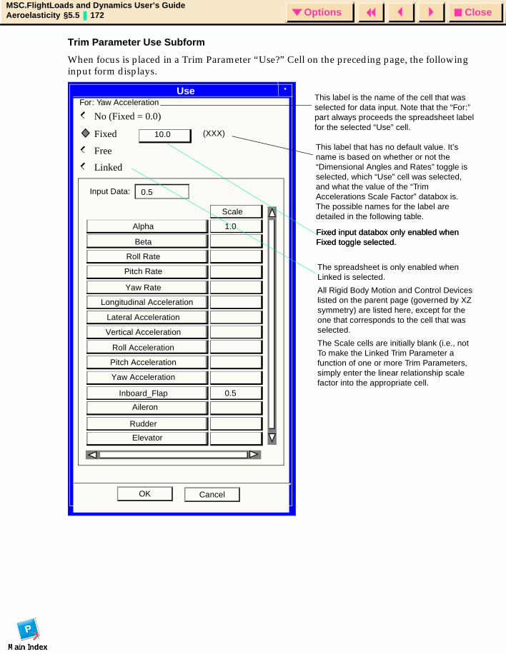
CloseOptionsMSC.FlightLoads and Dynamics User’s GuideAeroelasticity §5.5 172 Options
Trim Parameter Use Subform
When focus is placed in a Trim Parameter “Use?” Cell on the preceding page, the following input form displays.
Use
CancelOK
Fixed
No (Fixed = 0.0)
Free
10.0
Linked
Scale
Alpha
Beta
Roll Rate
Pitch Rate
Yaw Rate
1.0
Vertical Acceleration
Roll Acceleration
Pitch Acceleration
Yaw Acceleration
Inboard_Flap 0.5
Lateral Acceleration
Rudder
Longitudinal Acceleration
Aileron
Elevator
Input Data: 0.5
Fixed input databox only enabled when Fixed toggle selected.
The spreadsheet is only enabled when Linked is selected.
All Rigid Body Motion and Control Devices listed on the parent page (governed by XZ symmetry) are listed here, except for the one that corresponds to the cell that was selected.
The Scale cells are initially blank (i.e., not To make the Linked Trim Parameter a function of one or more Trim Parameters, simply enter the linear relationship scale factor into the appropriate cell.
(XXX)
For: Yaw AccelerationThis label is the name of the cell that was selected for data input. Note that the “For:” part always proceeds the spreadsheet label for the selected “Use” cell.
This label that has no default value. It’s name is based on whether or not the “Dimensional Angles and Rates” toggle is selected, which “Use” cell was selected, and what the value of the “Trim Accelerations Scale Factor” databox is. The possible names for the label are detailed in the following table.
Fixed input databox only enabled when Fixed toggle selected.
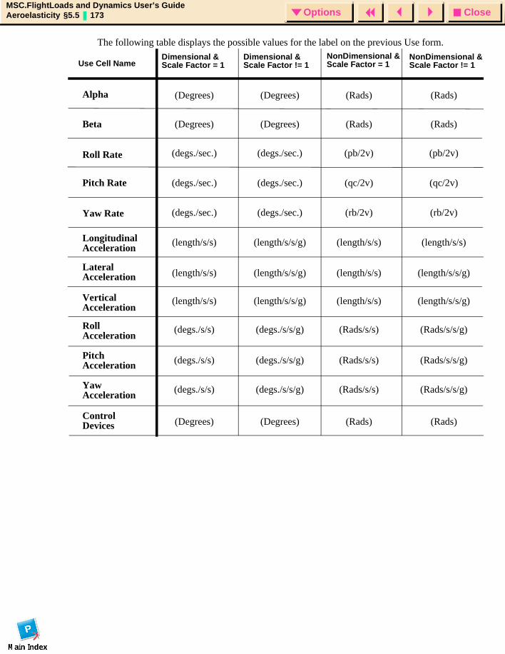
CloseOptionsMSC.FlightLoads and Dynamics User’s GuideAeroelasticity §5.5 173 Options
The following table displays the possible values for the label on the previous Use form.
Alpha
Beta
Roll Rate
Pitch Rate
Yaw Rate
LongitudinalAcceleration
LateralAcceleration
VerticalAcceleration
RollAcceleration
PitchAcceleration
YawAcceleration
ControlDevices
Dimensional &Scale Factor = 1
Dimensional &Scale Factor != 1
NonDimensional &Scale Factor = 1
NonDimensional &Scale Factor != 1Use Cell Name
(Degrees) (Degrees) (Rads)(Rads)
(Degrees) (Degrees) (Rads)(Rads)
(Degrees) (Degrees) (Rads)(Rads)
(degs./sec.) (degs./sec.) (pb/2v) (pb/2v)
(degs./sec.) (degs./sec.)
(degs./sec.) (degs./sec.)
(qc/2v) (qc/2v)
(rb/2v) (rb/2v)
(length/s/s) (length/s/s/g)
(length/s/s)
(length/s/s)
(length/s/s/g)
(length/s/s/g)
(length/s/s)
(length/s/s)
(length/s/s)
(length/s/s)
(length/s/s/g)
(length/s/s/g)
(degs./s/s)
(degs./s/s)
(degs./s/s)
(degs./s/s/g)
(degs./s/s/g)
(degs./s/s/g)
(Rads/s/s)
(Rads/s/s)
(Rads/s/s)
(Rads/s/s/g)
(Rads/s/s/g)
(Rads/s/s/g)
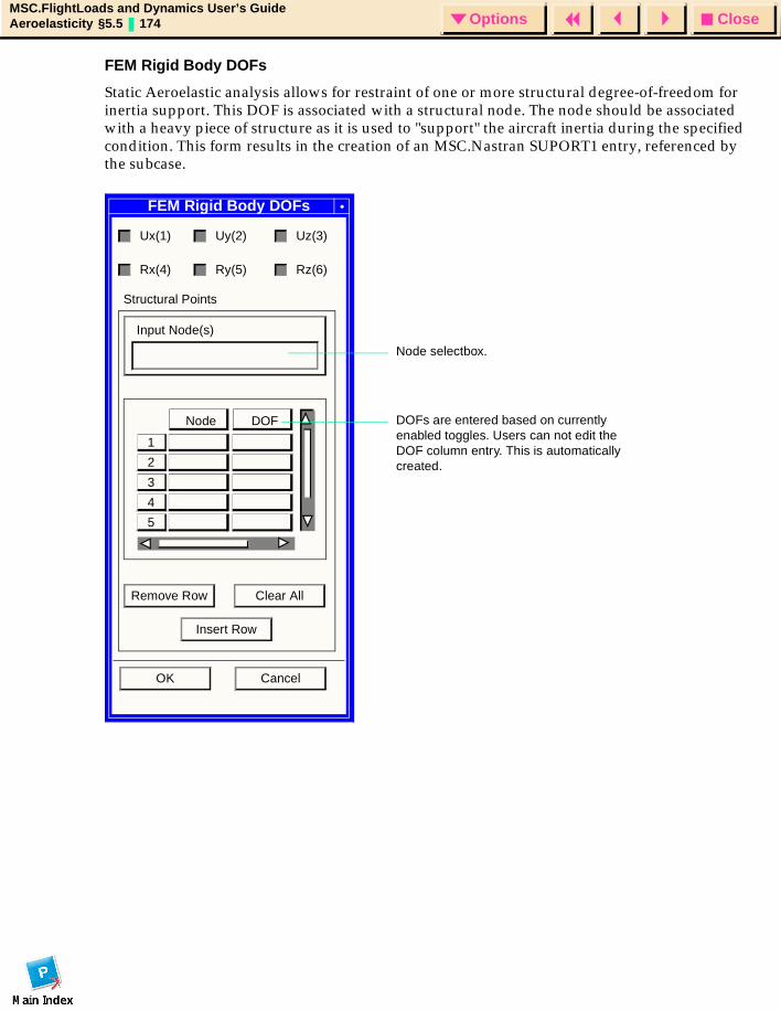
CloseOptionsMSC.FlightLoads and Dynamics User’s GuideAeroelasticity §5.5 174 Options
FEM Rigid Body DOFs
Static Aeroelastic analysis allows for restraint of one or more structural degree-of-freedom for inertia support. This DOF is associated with a structural node. The node should be associated with a heavy piece of structure as it is used to "support" the aircraft inertia during the specified condition. This form results in the creation of an MSC.Nastran SUPORT1 entry, referenced by the subcase.
FEM Rigid Body DOFs
Ux(1) Uy(2) Uz(3)
Rx(4) Ry(5) Rz(6)
Structural Points
Input Node(s)
Remove Row Clear All
Insert Row
OK Cancel
3
5
4
2
1
Node DOF
Node selectbox.
DOFs are entered based on currently enabled toggles. Users can not edit the DOF column entry. This is automatically created.
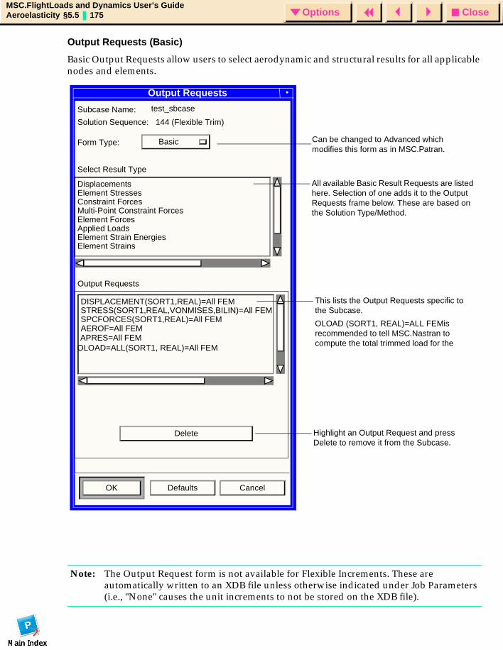
CloseOptionsMSC.FlightLoads and Dynamics User’s GuideAeroelasticity §5.5 175 Options
Output Requests (Basic)
Basic Output Requests allow users to select aerodynamic and structural results for all applicable nodes and elements.
Note: The Output Request form is not available for Flexible Increments. These are automatically written to an XDB file unless otherwise indicated under Job Parameters (i.e., "None" causes the unit increments to not be stored on the XDB file).
Output Requests
Subcase Name:
Solution Sequence: 144 (Flexible Trim)
Form Type: Basic
Select Result Type
DisplacementsElement StressesConstraint ForcesMulti-Point Constraint ForcesElement ForcesApplied LoadsElement Strain EnergiesElement Strains
Output Requests
DISPLACEMENT(SORT1,REAL)=All FEMSTRESS(SORT1,REAL,VONMISES,BILIN)=All FEMSPCFORCES(SORT1,REAL)=All FEM
Delete
OK Defaults Cancel
AEROF=All FEMAPRES=All FEM
All available Basic Result Requests are listed here. Selection of one adds it to the Output Requests frame below. These are based on the Solution Type/Method.
This lists the Output Requests specific to the Subcase.
OLOAD (SORT1, REAL)=ALL FEMis recommended to tell MSC.Nastran to compute the total trimmed load for the
Highlight an Output Request and press Delete to remove it from the Subcase.
OLOAD=ALL(SORT1, REAL)=All FEM
test_sbcase
Can be changed to Advanced which modifies this form as in MSC.Patran.
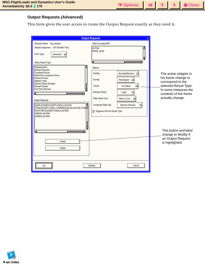
CloseOptionsMSC.FlightLoads and Dynamics User’s GuideAeroelasticity §5.5 176 Options
Output Requests (Advanced)
This form gives the user access to create the Output Request exactly as they need it.
Output Requests
Subcase Name:: test_sbcase
Solution Sequence: 144 (Flexible Trim)
Form Type: Advanced
Select Result Type
DisplacementsElement StressesConstraint ForcesMulti-Point Constraint ForcesElement ForcesApplied LoadsElement Strain EnergiesElement StrainsGrid Point Stresses
DISPLACEMENT(SORT1,REAL)=All FEM STRESS(SORT1,REAL,VONMISES,BILIN)=All FEM; PARAM SPCFORCES(SORT1,REAL)=All FEM
Delete
CancelDefaultsOK
Select Group(s)/SET
All FEMdefault_group
Options
Sorting: By Node/Element
Format: Rectangular
Tensor: Von Mises
Element Points: Cubic
Plate Strain Curv: Plane & Curv.
Composite Plate Opt: Element Stresses
Suppress Print for Result Type AEROF=All FEM APRES=All FEM
Output Requests
Create
The active widgets in his frame change to correspond to the selected Result Type. In some instances the contents of the frame actually change.
This button and label change to Modify if an Output Request is highlighted.
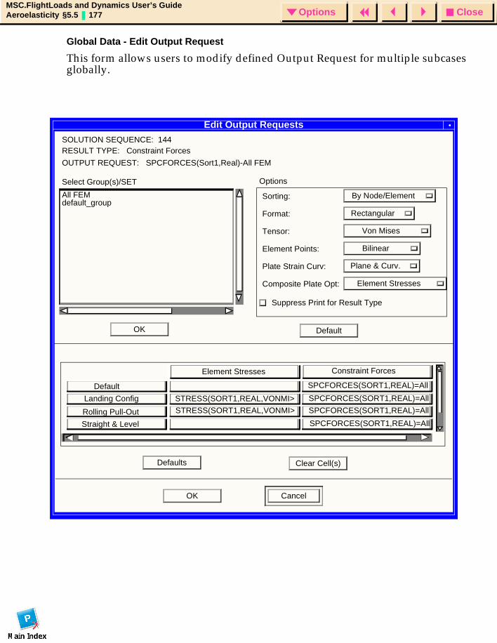
CloseOptionsMSC.FlightLoads and Dynamics User’s GuideAeroelasticity §5.5 177 Options
Global Data - Edit Output Request
This form allows users to modify defined Output Request for multiple subcases globally.
Edit Output RequestsSOLUTION SEQUENCE: 144RESULT TYPE: Constraint Forces
OK Cancel
Select Group(s)/SET
All FEMdefault_group
Options
Sorting: By Node/Element
Format: Rectangular
Tensor: Von Mises
Element Points: Bilinear
Plate Strain Curv: Plane & Curv.
Composite Plate Opt: Element Stresses
Suppress Print for Result Type
OUTPUT REQUEST: SPCFORCES(Sort1,Real)-All FEM
OK Default
Element Stresses Constraint Forces
Default
Landing Config
Rolling Pull-Out
Straight & Level
STRESS(SORT1,REAL,VONMI>
STRESS(SORT1,REAL,VONMI>
SPCFORCES(SORT1,REAL)=All
SPCFORCES(SORT1,REAL)=All
SPCFORCES(SORT1,REAL)=All
SPCFORCES(SORT1,REAL)=All
Defaults Clear Cell(s)
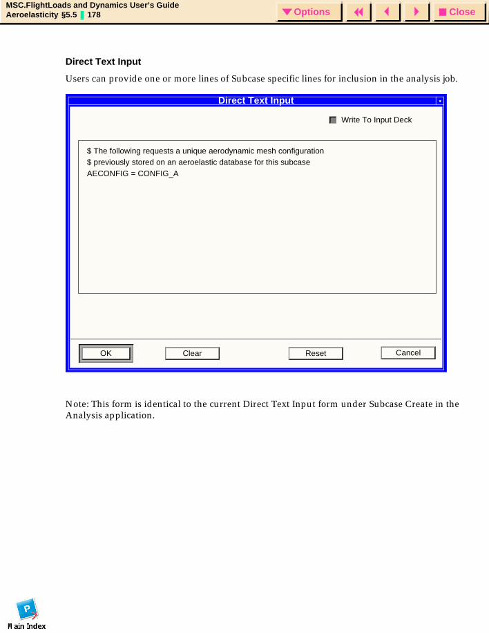
CloseOptionsMSC.FlightLoads and Dynamics User’s GuideAeroelasticity §5.5 178 Options
Direct Text Input
Users can provide one or more lines of Subcase specific lines for inclusion in the analysis job.
Note: This form is identical to the current Direct Text Input form under Subcase Create in the Analysis application.
Direct Text Input
OK Clear Reset Cancel
Write To Input Deck
$ The following requests a unique aerodynamic mesh configuration$ previously stored on an aeroelastic database for this subcaseAECONFIG = CONFIG_A
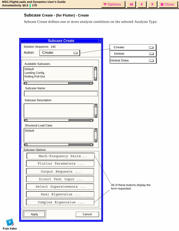
CloseOptionsMSC.FlightLoads and Dynamics User’s GuideAeroelasticity §5.5 179 Options
Subcase Create - (for Flutter) - Create
Subcase Create defines one or more analysis conditions on the selected Analysis Type.
Subcase Create
Solution Sequence: 145
Subcase Name
Subcase Description
Structural Load Case
Default
Subcase Options
Apply Cancel
Flutter Parameters ...
Available Subcases
Default
Output Requests ...
Direct Text Input ...
Select Superelements ...
Real Eigenvalue ...
Complex Eigenvalue ...
CreateAction:
Landing ConfigRolling Pull-Out
All of these buttons display the form requested.
Create
Delete
Global Data
Mach-Frequency Pairs...
CloseOptionsMSC.FlightLoads and Dynamics User’s GuideAeroelasticity §5.5 180 Options
NOTES:
1. Selecting an existing Subcase loads the appropriate data into the form.
2. The “Output Request” and “Direct Text Input” forms are the same as when the selected “Solution Type” is “Static Aeroelasticity”.
3. The “Select Superelements” button is only active if Superelements are present in the DB. (This cannot be added to Static Aero until changes are made to MSC.Nastran.)
4. By default the “Complex Eigenvalue” button is grayed out. It is only active when the “Method” on the “Flutter Parameters” form is set to K.
Subcase Create - (for Flutter) - Delete
This form (not shown) is exactly like the one for Static Aeroelasticity except that it allows users to delete any existing Flutter Subcases from the database.
Subcase Create - (for Flutter) - Global Data
This form (not shown) is exactly like the one for Static Aeroelasticity except that it allows the user to globally change the output request for the Selected Flutter subcases.
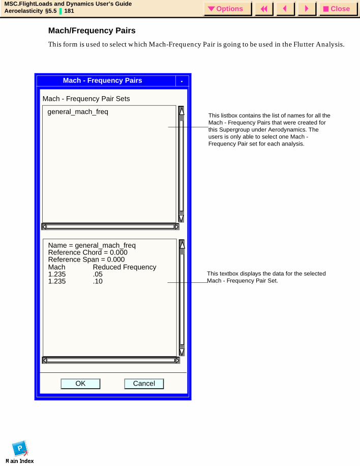
CloseOptionsMSC.FlightLoads and Dynamics User’s GuideAeroelasticity §5.5 181 Options
Mach/Frequency Pairs
This form is used to select which Mach-Frequency Pair is going to be used in the Flutter Analysis.
Mach - Frequency Pairs
CancelOK
Mach - Frequency Pair Sets
general_mach_freq
Name = general_mach_freqReference Chord = 0.000Reference Span = 0.000Mach Reduced Frequency
.051.2351.235 .10
This textbox displays the data for the selected Mach - Frequency Pair Set.
This listbox contains the list of names for all the Mach - Frequency Pairs that were created for this Supergroup under Aerodynamics. The users is only able to select one Mach - Frequency Pair set for each analysis.
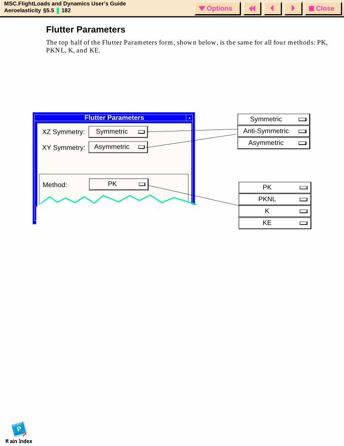
CloseOptionsMSC.FlightLoads and Dynamics User’s GuideAeroelasticity §5.5 182 Options
Flutter ParametersThe top half of the Flutter Parameters form, shown below, is the same for all four methods: PK, PKNL, K, and KE.
Flutter Parameters
SymmetricXZ Symmetry:
AsymmetricXY Symmetry:
PKMethod:
Symmetric
Anti-Symmetric
Asymmetric
PK
PKNL
K
KE
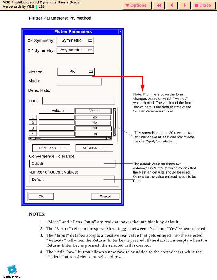
CloseOptionsMSC.FlightLoads and Dynamics User’s GuideAeroelasticity §5.5 183 Options
Flutter Parameters: PK Method
NOTES:
1. “Mach” and “Dens. Ratio” are real databoxes that are blank by default.
2. The “Vector” cells on the spreadsheet toggle between “No” and “Yes” when selected.
3. The “Input” databox accepts a positive real value that gets entered into the selected “Velocity” cell when the Return/Enter key is pressed. If the databox is empty when the Return/Enter key is pressed, the selected cell is cleared.
4. The “Add Row” button allows a new row to be added to the spreadsheet while the “Delete” button deletes the selected row.
Flutter Parameters
SymmetricXZ Symmetry:
AsymmetricXY Symmetry:
PKMethod:
Mach:
Dens. Ratio:
3
4
2
1
Velocity
Input:
Vector
No
No
No
No
Add Row ...
Convergence Tolerance:
Number of Output Values:
OK Cancel
Default
Default
Delete ...
Note: From here down the form changes based on which “Method” was selected. The version of the form shown here is the default state of the “Flutter Parameters” form.
The default value for these two databoxes is “Default” which means that the Nastran defaults should be used. Otherwise the value entered needs to be Real.
This spreadsheet has 20 rows to start and must have at least one row of data before “Apply” is selected.
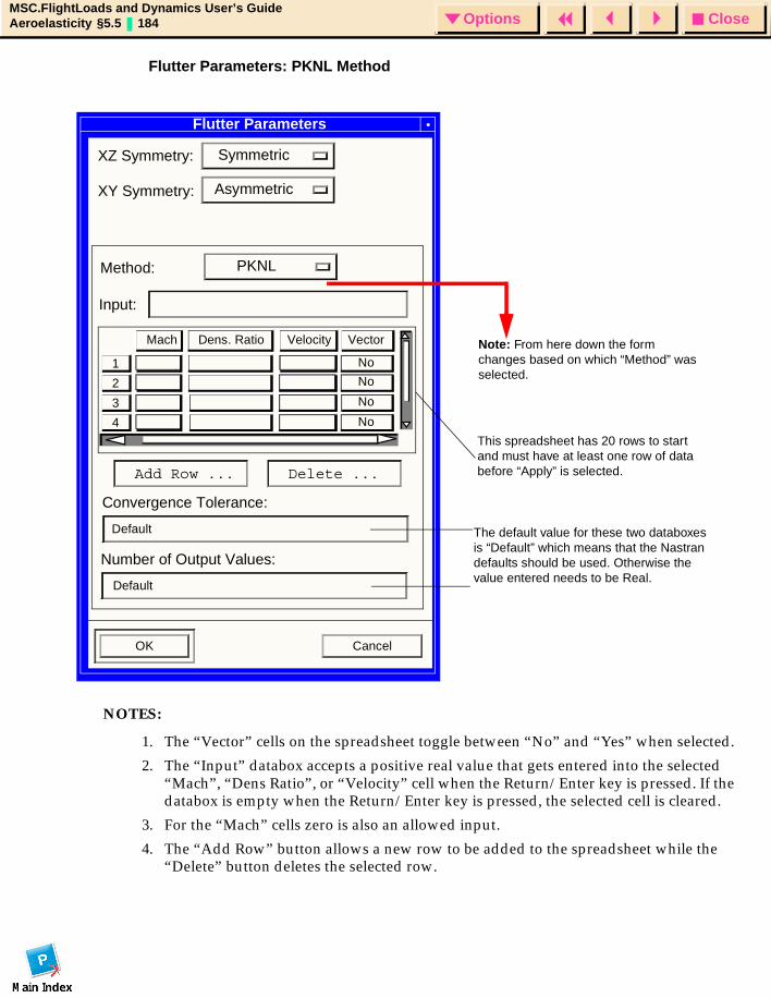
CloseOptionsMSC.FlightLoads and Dynamics User’s GuideAeroelasticity §5.5 184 Options
Flutter Parameters: PKNL Method
NOTES:
1. The “Vector” cells on the spreadsheet toggle between “No” and “Yes” when selected.
2. The “Input” databox accepts a positive real value that gets entered into the selected “Mach”, “Dens Ratio”, or “Velocity” cell when the Return/Enter key is pressed. If the databox is empty when the Return/Enter key is pressed, the selected cell is cleared.
3. For the “Mach” cells zero is also an allowed input.
4. The “Add Row” button allows a new row to be added to the spreadsheet while the “Delete” button deletes the selected row.
Flutter Parameters
SymmetricXZ Symmetry:
AsymmetricXY Symmetry:
PKNLMethod:
3
4
2
1
Mach
Input:
Vector
No
No
No
No
Add Row ...
Convergence Tolerance:
Number of Output Values:
OK Cancel
Default
Default
Delete ...
Dens. Ratio Velocity Note: From here down the form changes based on which “Method” was selected.
The default value for these two databoxes is “Default” which means that the Nastran defaults should be used. Otherwise the value entered needs to be Real.
This spreadsheet has 20 rows to start and must have at least one row of data before “Apply” is selected.
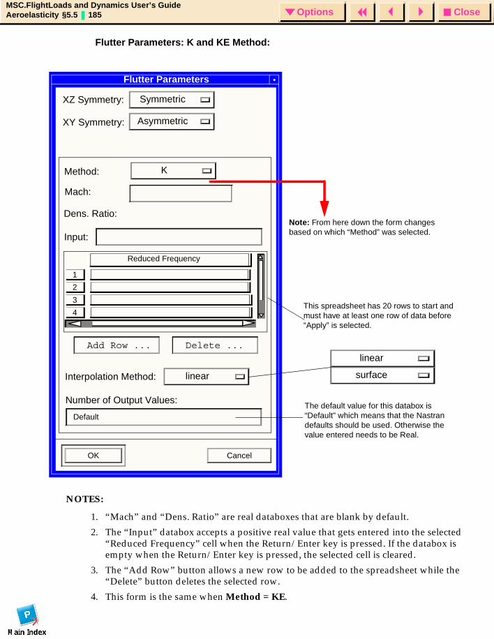
CloseOptionsMSC.FlightLoads and Dynamics User’s GuideAeroelasticity §5.5 185 Options
Flutter Parameters: K and KE Method:
NOTES:
1. “Mach” and “Dens. Ratio” are real databoxes that are blank by default.
2. The “Input” databox accepts a positive real value that gets entered into the selected “Reduced Frequency” cell when the Return/Enter key is pressed. If the databox is empty when the Return/Enter key is pressed, the selected cell is cleared.
3. The “Add Row” button allows a new row to be added to the spreadsheet while the “Delete” button deletes the selected row.
4. This form is the same when Method = KE.
Flutter Parameters
SymmetricXZ Symmetry:
AsymmetricXY Symmetry:
KMethod:
Mach:
Dens. Ratio:
3
4
2
1
Input:
Add Row ...
Number of Output Values:
OK Cancel
Default
Delete ...
Reduced Frequency
linearInterpolation Method:
linear
surface
Note: From here down the form changes based on which “Method” was selected.
This spreadsheet has 20 rows to start and must have at least one row of data before “Apply” is selected.
The default value for this databox is “Default” which means that the Nastran defaults should be used. Otherwise the value entered needs to be Real.

CloseOptionsMSC.FlightLoads and Dynamics User’s GuideAeroelasticity §5.5 186 Options
Output Requests
This form (not shown) is exactly like the one for Static Aeroelasticity and allows the user to create Output Requests.
Basic output request give the use the ability to select aerodynamic and structural results for all applicable nodes and elements.
Direct Text Input
This form (not shown) is exactly like the one for Static Aeroelasticity and allows the user to create Output Requests.
Users can provide one or more lines of subcase specific lines for inclusion in the analysis.
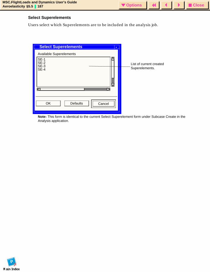
CloseOptionsMSC.FlightLoads and Dynamics User’s GuideAeroelasticity §5.5 187 Options
Select Superelements
Users select which Superelements are to be included in the analysis job.
Select Superelements
Available Superelements
SE-1SE-2SE-3SE-4
OK Defaults Cancel
Note: This form is identical to the current Select Superelement form under Subcase Create in the Analysis application.
List of current created Superelements.
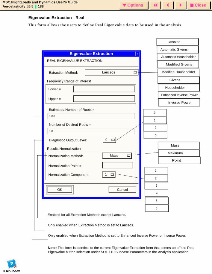
CloseOptionsMSC.FlightLoads and Dynamics User’s GuideAeroelasticity §5.5 188 Options
Eigenvalue Extraction - Real
This form allows the users to define Real Eigenvalue data to be used in the analysis.
Eigenvalue Extraction
REAL EIGENVALUE EXTRACTION
Extraction Method: Lanczos
Frequency Range of Interest
Lower =
Upper =
Estimated Number of Roots =
100
Number of Desired Roots =
10
Diagnostic Output Level: 0
Results Normalization
Normalization Method: Mass
Normalization Point =
Normalization Component: 1
OK Cancel
Note: This form is identical to the current Eigenvalue Extraction form that comes up off the Real Eigenvalue button selection under SOL 110 Subcase Parameters in the Analysis application.
Lanczos
Automatic Givens
Automatic Householder
Modified Givens
Modified Householder
Givens
Householder
Enhanced Inverse Power
Inverse Power
0
1
2
3
Mass
Maximum
Point
Enabled for all Extraction Methods except Lanczos.
Only enabled when Extraction Method is set to Lanczos.
Only enabled when Extraction Method is set to Enhanced Inverse Power or Inverse Power.
1
2
3
4
5
6
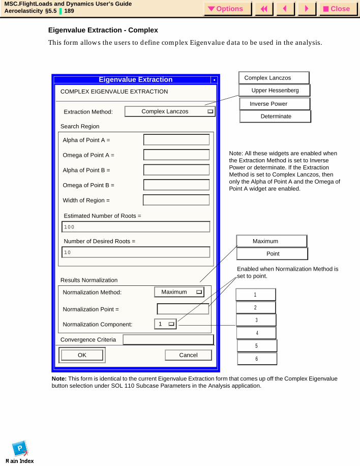
CloseOptionsMSC.FlightLoads and Dynamics User’s GuideAeroelasticity §5.5 189 Options
Eigenvalue Extraction - Complex
This form allows the users to define complex Eigenvalue data to be used in the analysis.
Eigenvalue Extraction
COMPLEX EIGENVALUE EXTRACTION
Extraction Method: Complex Lanczos
Search Region
Alpha of Point A =
Omega of Point A =
Results Normalization
Normalization Method: Maximum
Normalization Point =
Normalization Component: 1
OK Cancel
Alpha of Point B =
Omega of Point B =
Width of Region =
Estimated Number of Roots =
100
Number of Desired Roots =
10
Note: This form is identical to the current Eigenvalue Extraction form that comes up off the Complex Eigenvalue button selection under SOL 110 Subcase Parameters in the Analysis application.
Note: All these widgets are enabled when the Extraction Method is set to Inverse Power or determinate. If the Extraction Method is set to Complex Lanczos, then only the Alpha of Point A and the Omega of Point A widget are enabled.
Enabled when Normalization Method is set to point.
1
2
3
4
5
6
Maximum
Point
Complex Lanczos
Upper Hessenberg
Inverse Power
Determinate
Convergence Criteria
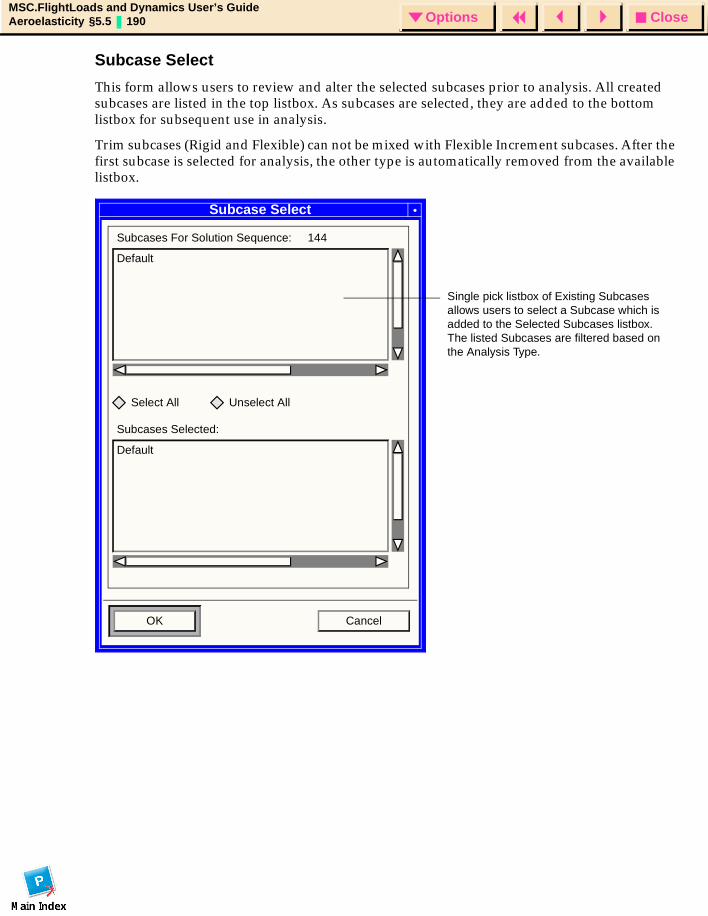
CloseOptionsMSC.FlightLoads and Dynamics User’s GuideAeroelasticity §5.5 190 Options
Subcase Select
This form allows users to review and alter the selected subcases prior to analysis. All created subcases are listed in the top listbox. As subcases are selected, they are added to the bottom listbox for subsequent use in analysis.
Trim subcases (Rigid and Flexible) can not be mixed with Flexible Increment subcases. After the first subcase is selected for analysis, the other type is automatically removed from the available listbox.
Subcase Select
Subcases For Solution Sequence: 144
Default
Select All Unselect All
Subcases Selected:
Default
OK Cancel
Single pick listbox of Existing Subcases allows users to select a Subcase which is added to the Selected Subcases listbox. The listed Subcases are filtered based on the Analysis Type.
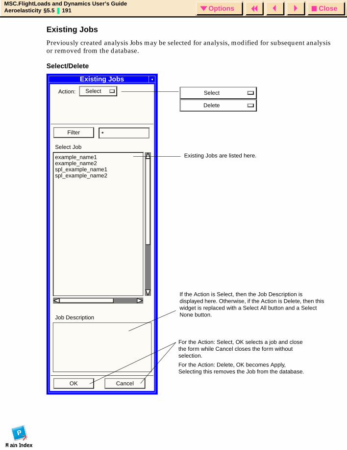
CloseOptionsMSC.FlightLoads and Dynamics User’s GuideAeroelasticity §5.5 191 Options
Existing Jobs
Previously created analysis Jobs may be selected for analysis, modified for subsequent analysis or removed from the database.
Select/Delete
Existing Jobs
Action: Select
Filter *
Select Job
example_name1example_name2spl_example_name1spl_example_name2
Job Description
OK Cancel
If the Action is Select, then the Job Description is displayed here. Otherwise, if the Action is Delete, then this widget is replaced with a Select All button and a Select None button.
Existing Jobs are listed here.
Select
Delete
For the Action: Select, OK selects a job and close the form while Cancel closes the form without selection.
For the Action: Delete, OK becomes Apply, Selecting this removes the Job from the database.
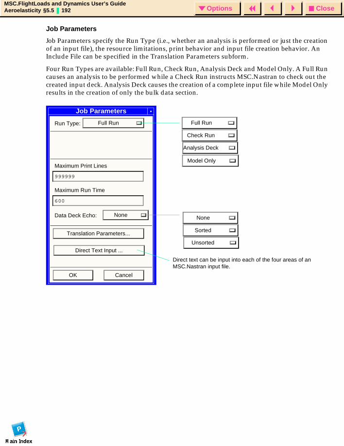
CloseOptionsMSC.FlightLoads and Dynamics User’s GuideAeroelasticity §5.5 192 Options
Job Parameters
Job Parameters specify the Run Type (i.e., whether an analysis is performed or just the creation of an input file), the resource limitations, print behavior and input file creation behavior. An Include File can be specified in the Translation Parameters subform.
Four Run Types are available: Full Run, Check Run, Analysis Deck and Model Only. A Full Run causes an analysis to be performed while a Check Run instructs MSC.Nastran to check out the created input deck. Analysis Deck causes the creation of a complete input file while Model Only results in the creation of only the bulk data section.
Job Parameters
Run Type: Full Run
Maximum Print Lines
999999
Maximum Run Time
600
Data Deck Echo: None
Translation Parameters...
OK Cancel
Model Only
Full Run
Check Run
Analysis Deck
None
Sorted
UnsortedDirect Text Input ...
Direct text can be input into each of the four areas of an MSC.Nastran input file.
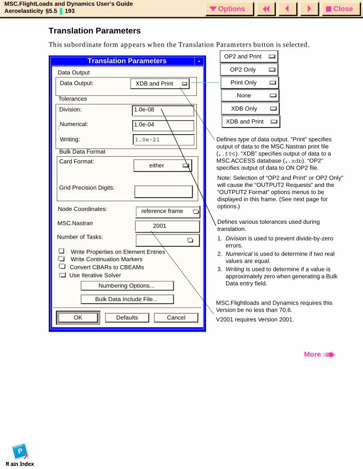
CloseOptionsMSC.FlightLoads and Dynamics User’s GuideAeroelasticity §5.5 193 Options
Translation Parameters
This subordinate form appears when the Translation Parameters button is selected.
Translation Parameters
Data Output
Data Output: XDB and Print
:
Writing: 1.0e-21
2001
Write Properties on Element Entries
Numbering Options...
Bulk Data Include File...
OK Defaults Cancel
Defines various tolerances used during translation.
1. Division is used to prevent divide-by-zero errors.
2. Numerical is used to determine if two real values are equal.
3. Writing is used to determine if a value is approximately zero when generating a Bulk Data entry field.
Defines type of data output. “Print” specifies output of data to the MSC.Nastran print file (*.f06). “XDB” specifies output of data to a MSC.ACCESS database (*.xdb). “OP2” specifies output of data to ON OP2 file.
More
Write Continuation MarkersConvert CBARs to CBEAMs
MSC.Flightloads and Dynamics requires this Version be no less than 70.6.
V2001 requires Version 2001.
Note: Selection of “OP2 and Print” or OP2 Only” will cause the “OUTPUT2 Requests” and the “OUTPUT2 Format” options menus to be displayed in this frame. (See next page for options.)
OP2 and Print
OP2 Only
Print Only
None
XDB Only
XDB and Print
Tolerances
1.0e-08
1.0e-04Numerical:
Division:
Bulk Data Format
eitherCard Format:
Grid Precision Digits:
reference frameNode Coordinates:
MSC.Nastran
Number of Tasks:
Use Iterative Solver
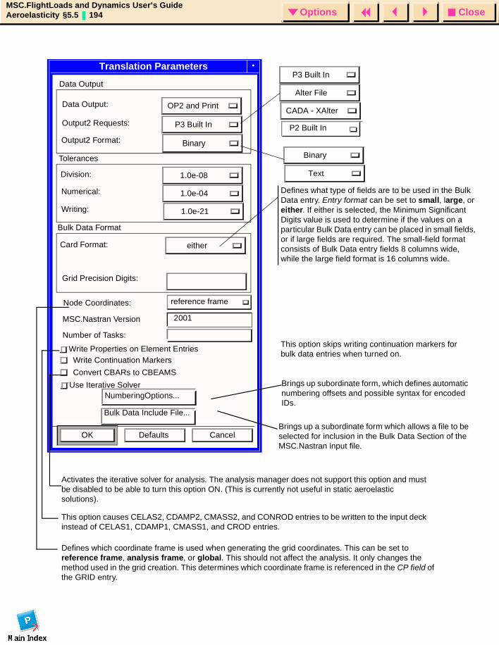
CloseOptionsMSC.FlightLoads and Dynamics User’s GuideAeroelasticity §5.5 194 Options
Defines what type of fields are to be used in the Bulk Data entry. Entry format can be set to small, large, or either. If either is selected, the Minimum Significant Digits value is used to determine if the values on a particular Bulk Data entry can be placed in small fields, or if large fields are required. The small-field format consists of Bulk Data entry fields 8 columns wide, while the large field format is 16 columns wide.
Brings up subordinate form, which defines automatic numbering offsets and possible syntax for encoded IDs.
Translation Parameters
Data Output:
Data Output
Grid Precision Digits:
Node Coordinates:
OK Defaults CancelBrings up a subordinate form which allows a file to be selected for inclusion in the Bulk Data Section of the MSC.Nastran input file.
Write Properties on Element Entries
This option causes CELAS2, CDAMP2, CMASS2, and CONROD entries to be written to the input deck instead of CELAS1, CDAMP1, CMASS1, and CROD entries.
Defines which coordinate frame is used when generating the grid coordinates. This can be set to reference frame, analysis frame, or global. This should not affect the analysis. It only changes the method used in the grid creation. This determines which coordinate frame is referenced in the CP field of the GRID entry.
This option skips writing continuation markers for bulk data entries when turned on.
Write Continuation Markers
Convert CBARs to CBEAMS
Activates the iterative solver for analysis. The analysis manager does not support this option and must be disabled to be able to turn this option ON. (This is currently not useful in static aeroelastic solutions).
P3 Built In
Alter File
CADA - XAlter
P2 Built In
Binary
P3 Built In
Binary
OP2 and Print
Output2 Requests:
Output2 Format:
1.0e-08
1.0e-04
1.0e-21
either
Tolerances
Division:
Numerical:
Writing:
Bulk Data Format
Card Format:
2001MSC.Nastran Version
Number of Tasks:
reference frame
Text
Use Iterative SolverNumberingOptions...
Bulk Data Include File...
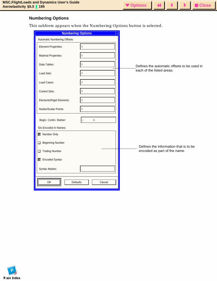
CloseOptionsMSC.FlightLoads and Dynamics User’s GuideAeroelasticity §5.5 195 Options
Numbering Options
This subform appears when the Numbering Options button is selected.
Numbering Options
Automatic Numbering Offsets:
Element Properties: 0
Material Properties: 0
Data Tables: 0
Load Sets: 0
Load Cases: 0
Control Sets: 0
Elements/Rigid Elements: 0
Nodes/Scalar Points: 0
Begin. Contin. Marker: + A
IDs Encoded in Names:
Number Only
Beginning Number
Trailing Number
Encoded Syntax
Syntax Marker: .
OK Defaults Cancel
Defines the automatic offsets to be used in each of the listed areas.
Defines the information that is to be encoded as part of the name.
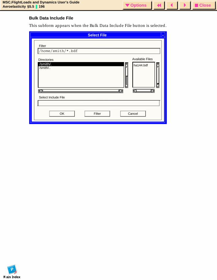
CloseOptionsMSC.FlightLoads and Dynamics User’s GuideAeroelasticity §5.5 196 Options
Bulk Data Include File
This subform appears when the Bulk Data Include File button is selected.
Select File
CancelOK
/home/smith/*.bdf
Filter
/smith/../smith/.
Directories Available Files
Select Include File
ha144.bdf
Filter
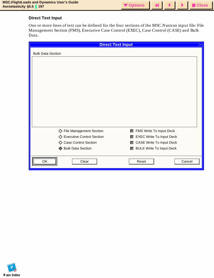
CloseOptionsMSC.FlightLoads and Dynamics User’s GuideAeroelasticity §5.5 197 Options
Direct Text Input
One or more lines of text can be defined for the four sections of the MSC.Nastran input file: File Management Section (FMS), Executive Case Control (EXEC), Case Control (CASE) and Bulk Data.
Direct Text Input
Bulk Data Section
File Management Section
Executive Control Section
Case Control Section
Bulk Data Section
FMS Write To Input Deck
EXEC Write To Input Deck
CASE Write To Input Deck
BULK Write To Input Deck
OK Clear Reset Cancel

CloseOptionsMSC.FlightLoads and Dynamics User’s GuideAeroelasticity §5.5 198 Options

CloseOptionsMSC.FlightLoads and Dynamics User’s GuideResults Browser § 199 Options
MSC.FlightLoads and Dynamics User’s Guide
CHAPTER
6 Results Browser
Introduction
Attach Results Data
Flexible Increment Filter
Loads Browser
Export
Results Viewer
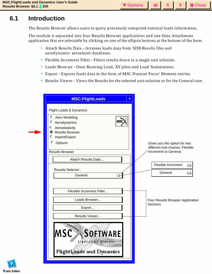
CloseOptionsMSC.FlightLoads and Dynamics User’s GuideResults Browser §6.1 200 Options
6.1 IntroductionThe Results Browser allows users to query previously computed external loads information.
The module is separated into four Results Browser applications and one Data Attachment application that are selectable by clicking on one of the ellipsis buttons at the bottom of the form.
• Attach Results Data - Accesses loads data from XDB Results files and aerodynamic/aeroelastic databases.
• Flexible Increment Filter - Filters results down to a single unit solution.
• Loads Browser - Does Running Load, XY plots and Load Summations.
• Export - Exports loads data in the form of MSC.Nastran Force/Moment entries.
• Results Viewer - Views the Results for the selected unit solution or for the General case.
MSC.FlightLoads
Aero Modeling Aerodynamics
Aeroelasticity
Import/Export
Options
Flight Loads & Dynamics
Export...
Flexible Increment Filter...
Four Results Browser Application Sections
Results Browser
Results Browser
Attach Results Data ...
Results Viewer...
General
Gives you the option for two different tool choices: Flexible Increment or General.
Flexible Increment
General
Loads Browser...
Results Selector:
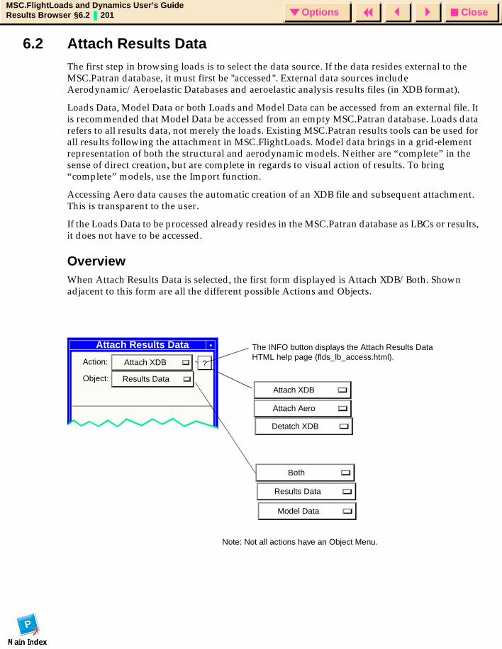
CloseOptionsMSC.FlightLoads and Dynamics User’s GuideResults Browser §6.2 201 Options
6.2 Attach Results Data The first step in browsing loads is to select the data source. If the data resides external to the MSC.Patran database, it must first be "accessed". External data sources include Aerodynamic/Aeroelastic Databases and aeroelastic analysis results files (in XDB format).
Loads Data, Model Data or both Loads and Model Data can be accessed from an external file. It is recommended that Model Data be accessed from an empty MSC.Patran database. Loads data refers to all results data, not merely the loads. Existing MSC.Patran results tools can be used for all results following the attachment in MSC.FlightLoads. Model data brings in a grid-element representation of both the structural and aerodynamic models. Neither are “complete” in the sense of direct creation, but are complete in regards to visual action of results. To bring “complete” models, use the Import function.
Accessing Aero data causes the automatic creation of an XDB file and subsequent attachment. This is transparent to the user.
If the Loads Data to be processed already resides in the MSC.Patran database as LBCs or results, it does not have to be accessed.
OverviewWhen Attach Results Data is selected, the first form displayed is Attach XDB/Both. Shown adjacent to this form are all the different possible Actions and Objects.
Attach Results Data
Action: Attach XDB
Object: Results Data
Results Data
Model Data
Attach XDB
Attach Aero
Both
The INFO button displays the Attach Results Data HTML help page (flds_lb_access.html).
?
Note: Not all actions have an Object Menu.
Detatch XDB

CloseOptionsMSC.FlightLoads and Dynamics User’s GuideResults Browser §6.2 202 Options
Attach Results DataThe following is a list of the Results Browser Forms and subforms related to Attach Results Data.
• Attach XDB
• Translation Parameters Subform
• Attach Aero
• Detach XDB
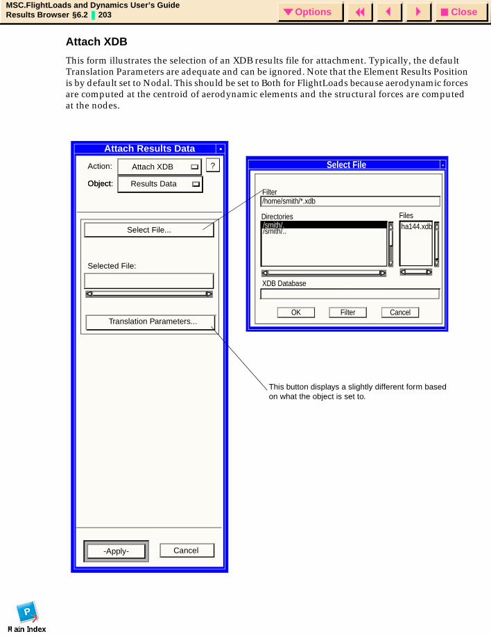
CloseOptionsMSC.FlightLoads and Dynamics User’s GuideResults Browser §6.2 203 Options
Attach XDB
This form illustrates the selection of an XDB results file for attachment. Typically, the default Translation Parameters are adequate and can be ignored. Note that the Element Results Position is by default set to Nodal. This should be set to Both for FlightLoads because aerodynamic forces are computed at the centroid of aerodynamic elements and the structural forces are computed at the nodes.
Attach Results Data
Action: Attach XDB
Object: Object: Results Data
Select File...
-Apply- Cancel
Select File
CancelOK
/home/smith/*.xdbFilter
/smith/../smith/.Directories Files
XDB Database
ha144.xdb
Filter
?
Selected File:
Translation Parameters...
This button displays a slightly different form based on what the object is set to.
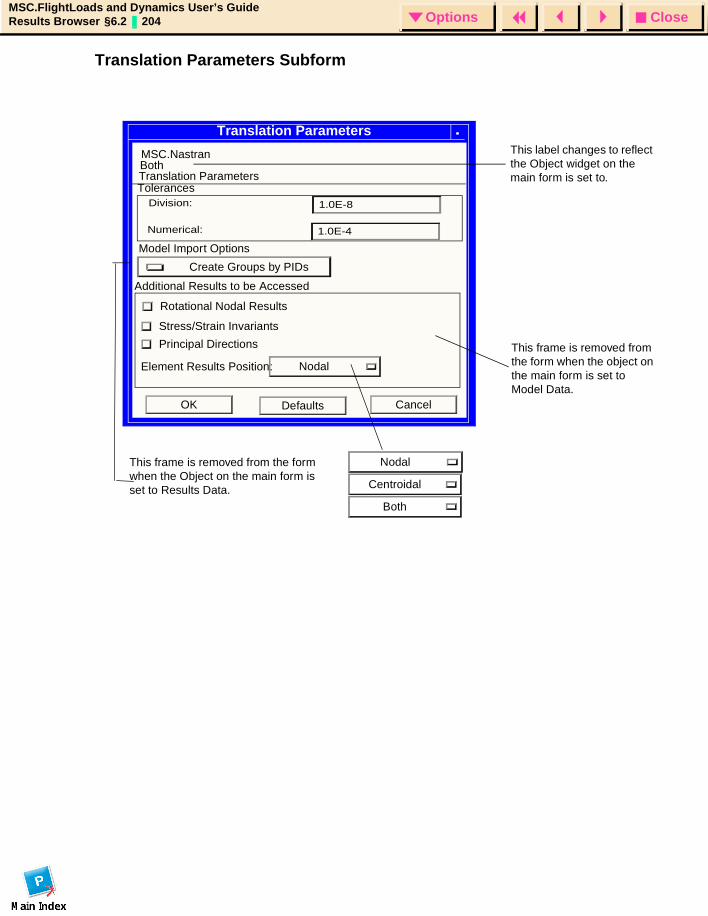
CloseOptionsMSC.FlightLoads and Dynamics User’s GuideResults Browser §6.2 204 Options
Translation Parameters Subform
Translation Parameters
CancelOK Defaults
Principal Directions
Stress/Strain Invariants
Rotational Nodal Results
Element Results Position: Nodal
Additional Results to be Accessed
MSC.Nastran BothTranslation Parameters
1.0E-8
TolerancesDivision:
1.0E-4Numerical:
Nodal
Centroidal
Both
This label changes to reflect the Object widget on the main form is set to.
This frame is removed from the form when the object on the main form is set to Model Data.
This frame is removed from the form when the Object on the main form is set to Results Data.
Create Groups by PIDs
Model Import Options
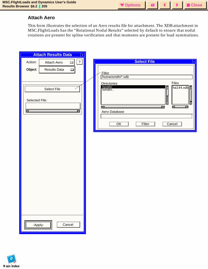
CloseOptionsMSC.FlightLoads and Dynamics User’s GuideResults Browser §6.2 205 Options
Attach Aero
This form illustrates the selection of an Aero results file for attachment. The XDB attachment in MSC.FlightLoads has the “Rotational Nodal Results” selected by default to ensure that nodal rotations are present for spline verification and that moments are present for load summations.
Attach Results Data
Action: Attach Aero
Object: Object: Results Data
Select File
-Apply- Cancel
Select File
CancelOK
/home/smith/*.xdbFilter
/smith/../smith/.Directories Files
Aero Database
ha144.xdb
Filter
?
Selected File:
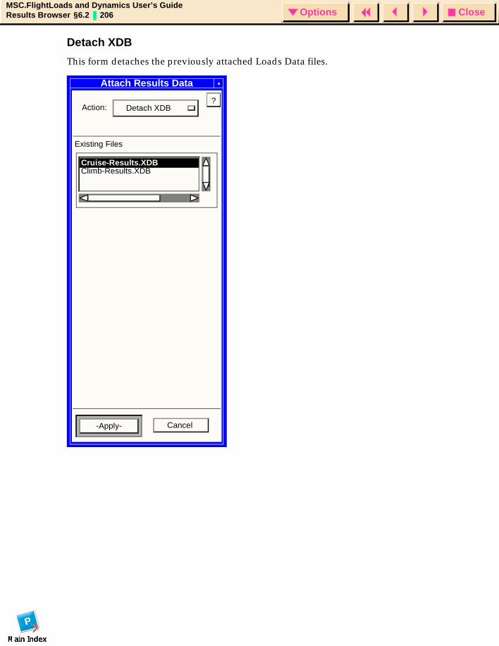
CloseOptionsMSC.FlightLoads and Dynamics User’s GuideResults Browser §6.2 206 Options
Detach XDB
This form detaches the previously attached Loads Data files.
Attach Results Data
Action: Detach XDB
-Apply-
Climb-Results.XDBCruise-Results.XDB
Cancel
?
Existing Files
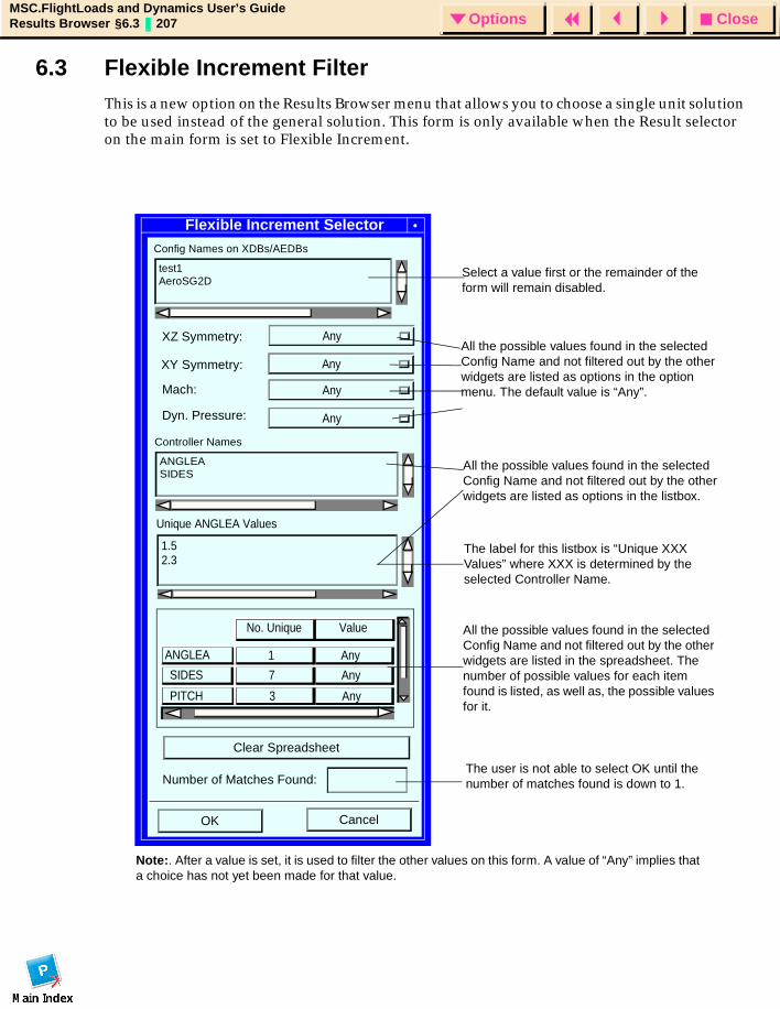
CloseOptionsMSC.FlightLoads and Dynamics User’s GuideResults Browser §6.3 207 Options
6.3 Flexible Increment FilterThis is a new option on the Results Browser menu that allows you to choose a single unit solution to be used instead of the general solution. This form is only available when the Result selector on the main form is set to Flexible Increment.
Flexible Increment Selector
XZ Symmetry:
Mach:
OK Cancel
Value
ANGLEA
SIDES
PITCH
Any
Any
Any
Any
Any
No. Unique
1
7
3
Config Names on XDBs/AEDBs
test1AeroSG2D
Dyn. Pressure: Any
Controller Names
ANGLEASIDES
Unique ANGLEA Values
1.52.3
Clear Spreadsheet
Number of Matches Found:
XY Symmetry: Any
Note:. After a value is set, it is used to filter the other values on this form. A value of “Any” implies that a choice has not yet been made for that value.
Select a value first or the remainder of the form will remain disabled.
All the possible values found in the selected Config Name and not filtered out by the other widgets are listed as options in the option menu. The default value is “Any”.
All the possible values found in the selected Config Name and not filtered out by the other widgets are listed as options in the listbox.
The label for this listbox is “Unique XXX Values” where XXX is determined by the selected Controller Name.
All the possible values found in the selected Config Name and not filtered out by the other widgets are listed in the spreadsheet. The number of possible values for each item found is listed, as well as, the possible values for it.
The user is not able to select OK until the number of matches found is down to 1.
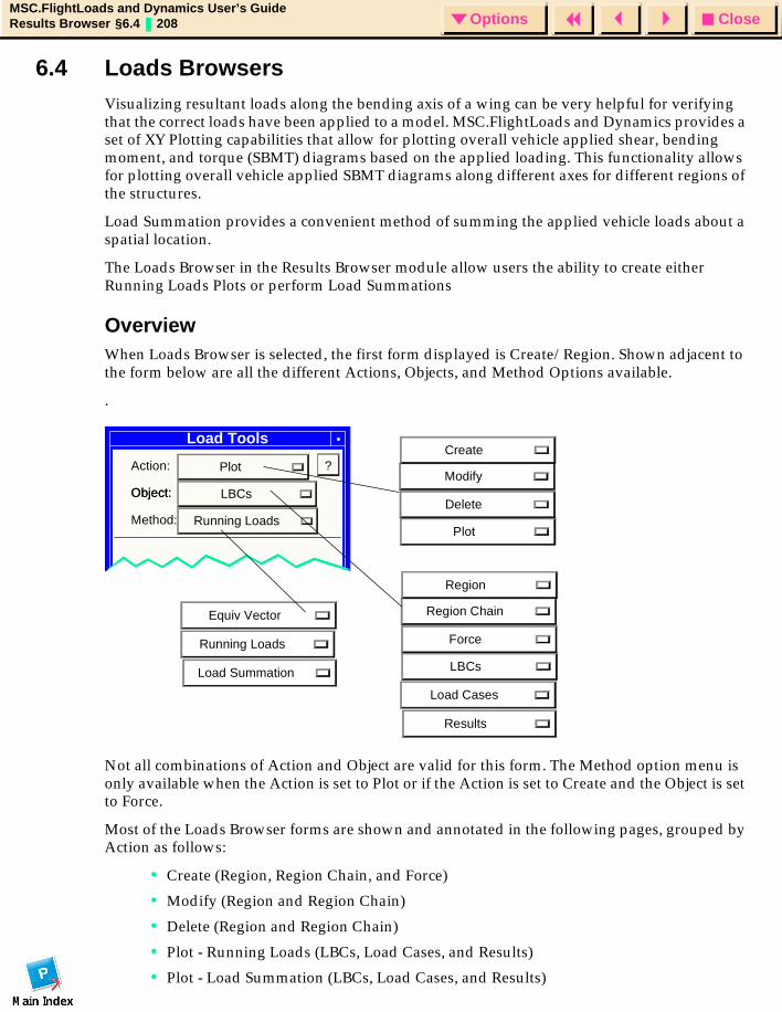
CloseOptionsMSC.FlightLoads and Dynamics User’s GuideResults Browser §6.4 208 Options
6.4 Loads BrowsersVisualizing resultant loads along the bending axis of a wing can be very helpful for verifying that the correct loads have been applied to a model. MSC.FlightLoads and Dynamics provides a set of XY Plotting capabilities that allow for plotting overall vehicle applied shear, bending moment, and torque (SBMT) diagrams based on the applied loading. This functionality allows for plotting overall vehicle applied SBMT diagrams along different axes for different regions of the structures.
Load Summation provides a convenient method of summing the applied vehicle loads about a spatial location.
The Loads Browser in the Results Browser module allow users the ability to create either Running Loads Plots or perform Load Summations
OverviewWhen Loads Browser is selected, the first form displayed is Create/Region. Shown adjacent to the form below are all the different Actions, Objects, and Method Options available.
.
Not all combinations of Action and Object are valid for this form. The Method option menu is only available when the Action is set to Plot or if the Action is set to Create and the Object is set to Force.
Most of the Loads Browser forms are shown and annotated in the following pages, grouped by Action as follows:
• Create (Region, Region Chain, and Force)
• Modify (Region and Region Chain)
• Delete (Region and Region Chain)
• Plot - Running Loads (LBCs, Load Cases, and Results)
• Plot - Load Summation (LBCs, Load Cases, and Results)
Load Tools
Action: Plot
Object: Object: LBCs
Method: Running Loads
Equiv Vector
Running Loads
?
Plot
Delete
Modify
Create
LBCs
Force
Region Chain
Region
Load Cases
Load Summation
Results

CloseOptionsMSC.FlightLoads and Dynamics User’s GuideResults Browser §6.4 209 Options
Loads Browser
Following is a list of the Results Browser forms and subforms related to the Loads Browser:
• Create/Region
• Create/Region Chain
• Create/Force
• Modify/Region
• Modify/Region Chain
• Delete/Region
• Delete/Region Chain
• Plot/LBCs/Running Loads
• Plot/Load Cases/Running Loads
• Plot/Results/Running Loads
• Plot -- Running Load Subforms
• Plot/LBCs/Load Summation
• Plot--Load Summation Subforms
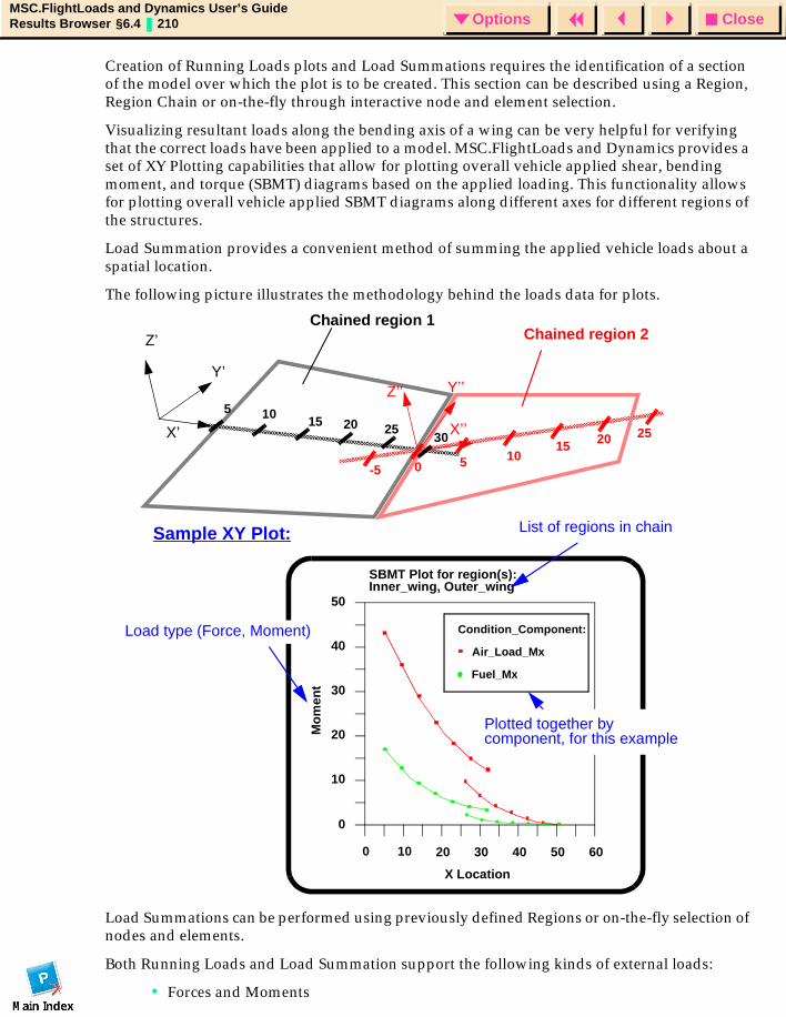
CloseOptionsMSC.FlightLoads and Dynamics User’s GuideResults Browser §6.4 210 Options
Creation of Running Loads plots and Load Summations requires the identification of a section of the model over which the plot is to be created. This section can be described using a Region, Region Chain or on-the-fly through interactive node and element selection.
Visualizing resultant loads along the bending axis of a wing can be very helpful for verifying that the correct loads have been applied to a model. MSC.FlightLoads and Dynamics provides a set of XY Plotting capabilities that allow for plotting overall vehicle applied shear, bending moment, and torque (SBMT) diagrams based on the applied loading. This functionality allows for plotting overall vehicle applied SBMT diagrams along different axes for different regions of the structures.
Load Summation provides a convenient method of summing the applied vehicle loads about a spatial location.
The following picture illustrates the methodology behind the loads data for plots.
Load Summations can be performed using previously defined Regions or on-the-fly selection of nodes and elements.
Both Running Loads and Load Summation support the following kinds of external loads:
• Forces and Moments
Chained region 2Chained region 1
X’
Y’
Z’
X’’
Y’’Z’’5 10
15 20 25
-5 0 5 1015 20 25
0 10 20 30 40 50 60
0
10
20
30
40
50
X Location
Mo
men
t
Air_Load_Mx
Fuel_Mx
SBMT Plot for region(s): Inner_wing, Outer_wing
Condition_Component:
List of regions in chainSample XY Plot:
Plotted together bycomponent, for this example
30
Load type (Force, Moment)
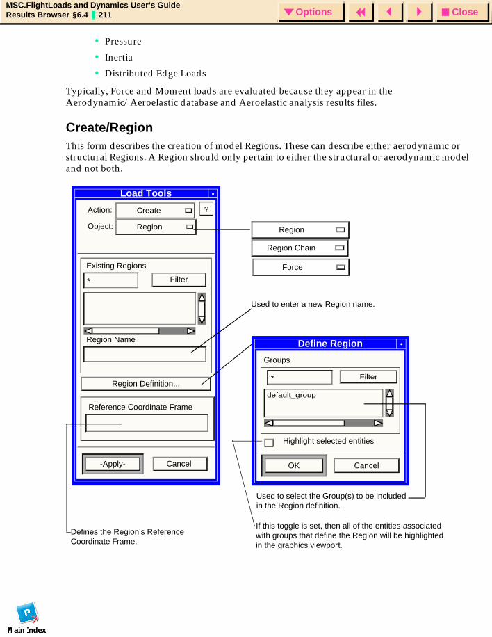
CloseOptionsMSC.FlightLoads and Dynamics User’s GuideResults Browser §6.4 211 Options
• Pressure
• Inertia
• Distributed Edge Loads
Typically, Force and Moment loads are evaluated because they appear in the Aerodynamic/Aeroelastic database and Aeroelastic analysis results files.
Create/RegionThis form describes the creation of model Regions. These can describe either aerodynamic or structural Regions. A Region should only pertain to either the structural or aerodynamic model and not both.
Load Tools
Action: Create
Object: Region
Existing Regions
* Filter
Region Name
Region Definition...
Reference Coordinate Frame
-Apply-
Used to enter a new Region name.
Cancel
Define Region
Groups
* Filter
default_group
OK Cancel
Defines the Region’s Reference Coordinate Frame.
Used to select the Group(s) to be included in the Region definition.
Region
Region Chain
?
Highlight selected entities
Force
If this toggle is set, then all of the entities associated with groups that define the Region will be highlighted in the graphics viewport.
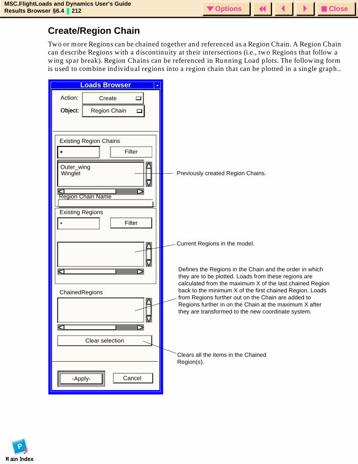
CloseOptionsMSC.FlightLoads and Dynamics User’s GuideResults Browser §6.4 212 Options
Create/Region ChainTwo or more Regions can be chained together and referenced as a Region Chain. A Region Chain can describe Regions with a discontinuity at their intersections (i.e., two Regions that follow a wing spar break). Region Chains can be referenced in Running Load plots. The following form is used to combine individual regions into a region chain that can be plotted in a single graph..
Loads Browser
Action: Create
Object:
* Filter* Filter
Object: Region Chain
Existing Region Chains
* Filter* Filter
Existing Regions
* Filter
ChainedRegions
Clear selection
Defines the Regions in the Chain and the order in which they are to be plotted. Loads from these regions are calculated from the maximum X of the last chained Region back to the minimum X of the first chained Region. Loads from Regions further out on the Chain are added to Regions further in on the Chain at the maximum X after they are transformed to the new coordinate system.
Previously created Region Chains.
Current Regions in the model.
Clears all the items in the Chained Region(s).
-Apply- Cancel
Outer_wingWinglet
Region Chain Name

CloseOptionsMSC.FlightLoads and Dynamics User’s GuideResults Browser §6.4 213 Options
Create/ForceThe Create Force functionality enables a user to create an equivalent force vector that is derived from all of the nodal forces within any combination of existing load cases. The user has the ability to define the load summation point where the equivalent force is applied as well as the region over which the load summation is performed. The resultant force can either be used to replace the contents of an existing load case or to create an entirely new load case.
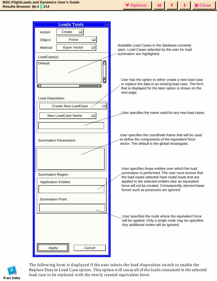
CloseOptionsMSC.FlightLoads and Dynamics User’s GuideResults Browser §6.4 214 Options
The following form is displayed if the user selects the load disposition switch to enable the Replace Data in Load Case option. This option will cause all of the loads contained in the selected load case to be replaced with the newly created equivalent force.
Loads Tools
Action: Create
Object: Force
Method: Equiv Vector
LoadCase(s)
Default
Load Disposition
Create New LoadCase
New LoadCase Name
Summation Parameters
Summation Region
Application Entities
Summation Point
-Apply- Cancel
Available Load Cases in the database currently open. Load Cases selected by the user for load summation are highlighted.
User has the option to either create a new load case or replace the data in an existing load case. The form that is displayed for the later option is shown on the next page.
User specifies the name used for any new load cases.
User specifies those entities over which the load summation is performed. The user must ensure that the load cases selected have nodal loads that are applied to the selected entities else an equivalent force will not be created. Consequently, element base forces such as pressures are ignored.
User specifies the node where the equivalent force will be applied. Only a single node may be specified. Any additional nodes will be ignored.
User specifies the coordinate frame that will be used to define the components of the equivalent force vector. The default is the global rectangular.
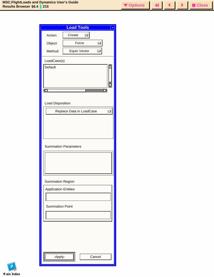
CloseOptionsMSC.FlightLoads and Dynamics User’s GuideResults Browser §6.4 215 Options
Load Tools
Action: Create
Object: Force
Method: Equiv Vector
LoadCase(s)
Default
Load Disposition
Replace Data in LoadCase
Summation Parameters
Summation Region
Application Entities
Summation Point
-Apply- Cancel
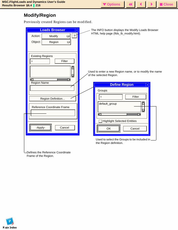
CloseOptionsMSC.FlightLoads and Dynamics User’s GuideResults Browser §6.4 216 Options
Modify/RegionPreviously created Regions can be modified.
Loads Browser
Action: Modify
Object: Region
Existing Regions
* Filter
Region Name
Region Definition...
Reference Coordinate Frame
-Apply- Cancel
Define Region
Groups
* Filter
default_group
OK Cancel
Used to enter a new Region name, or to modify the name of the selected Region.
Defines the Reference Coordinate Frame of the Region.
Used to select the Groups to be included in the Region definition.
The INFO button displays the Modify Loads Browser HTML help page (flds_lb_modify.html).
?
Highlight Selected Entities
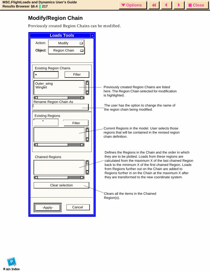
CloseOptionsMSC.FlightLoads and Dynamics User’s GuideResults Browser §6.4 217 Options
Modify/Region ChainPreviously created Region Chains can be modified.
Loads Tools
Action: Modify
Object:
* Filter* Filter
Object: Region Chain
Existing Region Chains
* Filter* Filter
Filter
Chained Regions
Clear selection
Defines the Regions in the Chain and the order in which they are to be plotted. Loads from these regions are calculated from the maximum X of the last chained Region back to the minimum X of the first chained Region. Loads from Regions further out on the Chain are added to Regions further in on the Chain at the maximum X after they are transformed to the new coordinate system.
Previously created Region Chains are listed here. The Region Chain selected for modification is highlighted.
Current Regions in the model. User selects those regions that will be contained in the revised region chain definition.
Clears all the items in the Chained Region(s).
-Apply- Cancel
Outer_wingWinglet
*
Existing Regions
Rename Region Chain AsThe user has the option to change the name of the region chain being modified.
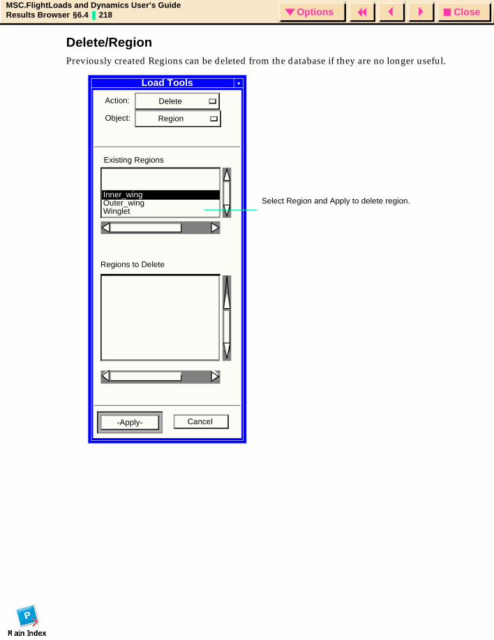
CloseOptionsMSC.FlightLoads and Dynamics User’s GuideResults Browser §6.4 218 Options
Delete/RegionPreviously created Regions can be deleted from the database if they are no longer useful.
Load Tools
Action: Delete
Object: Region
Existing Regions
-Apply-
Outer_wingWinglet
Inner_wing
Cancel
Regions to Delete
Select Region and Apply to delete region.
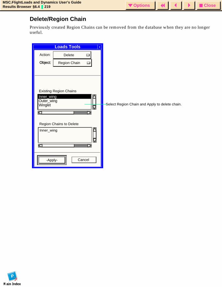
CloseOptionsMSC.FlightLoads and Dynamics User’s GuideResults Browser §6.4 219 Options
Delete/Region ChainPreviously created Region Chains can be removed from the database when they are no longer useful.
Select Region Chain and Apply to delete chain.
Action: Delete
Object: Object: Region Chain
Region Chains to Delete
Loads Tools
Outer_wingWinglet
Inner_wing
Inner_wing
-Apply- Cancel
Existing Region Chains
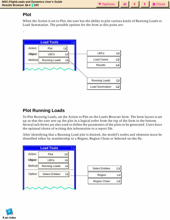
CloseOptionsMSC.FlightLoads and Dynamics User’s GuideResults Browser §6.4 220 Options
PlotWhen the Action is set to Plot, the user has the ability to plot various kinds of Running Loads or Load Summation. The possible options for the form at this point are:
.
Plot Running LoadsTo Plot Running Loads, set the Action to Plot on the Loads Browser form. The form layout is set up so that the user sets up the plot in a logical order from the top of the form to the bottom. Several sub-forms are also used to define the parameters of the plots to be generated. Users have the optional choice of writing this information to a report file.
After identifying that a Running Load plot is desired, the model’s nodes and elements must be identified either by membership to a Region, Region Chain or Selected on-the-fly.
Load Tools
Action: Plot
Object: Object: LBCs
Method: Running Loads
LBCs
Load Cases
Results
Running Loads
Load Summation
Load Tools
Action: Plot
Object: Object: LBCs
Method: Running Loads
Region
Region Chain
Select Entities
Option: Select Entities
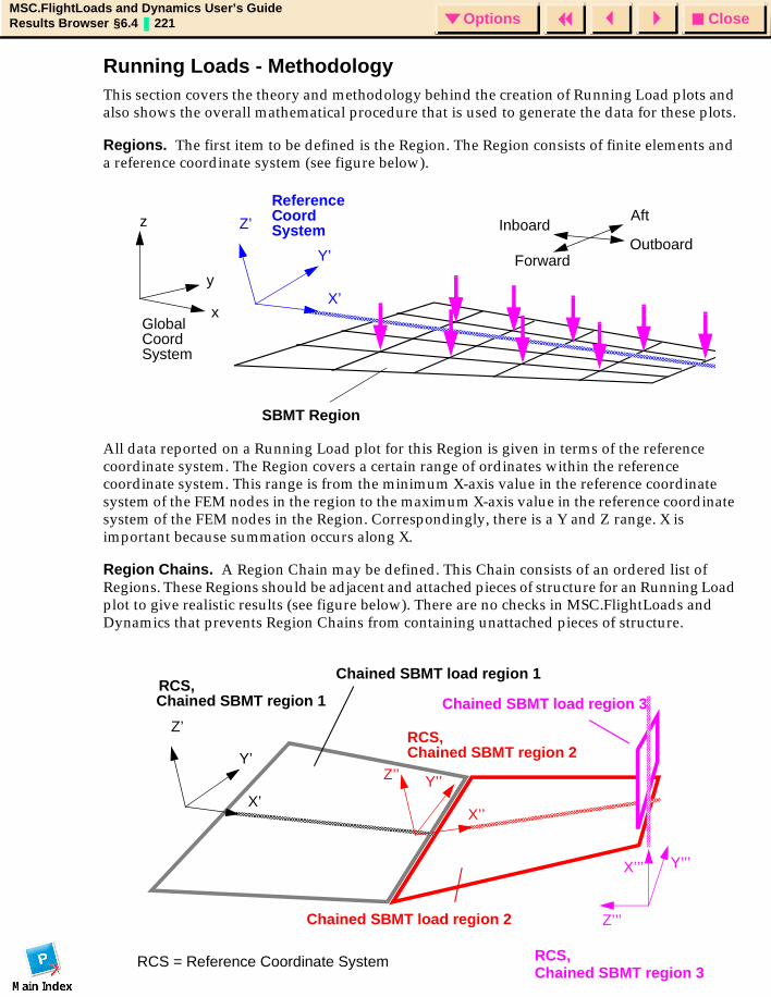
CloseOptionsMSC.FlightLoads and Dynamics User’s GuideResults Browser §6.4 221 Options
Running Loads - MethodologyThis section covers the theory and methodology behind the creation of Running Load plots and also shows the overall mathematical procedure that is used to generate the data for these plots.
Regions. The first item to be defined is the Region. The Region consists of finite elements and a reference coordinate system (see figure below).
All data reported on a Running Load plot for this Region is given in terms of the reference coordinate system. The Region covers a certain range of ordinates within the reference coordinate system. This range is from the minimum X-axis value in the reference coordinate system of the FEM nodes in the region to the maximum X-axis value in the reference coordinate system of the FEM nodes in the Region. Correspondingly, there is a Y and Z range. X is important because summation occurs along X.
Region Chains. A Region Chain may be defined. This Chain consists of an ordered list of Regions. These Regions should be adjacent and attached pieces of structure for an Running Load plot to give realistic results (see figure below). There are no checks in MSC.FlightLoads and Dynamics that prevents Region Chains from containing unattached pieces of structure.
x
y
z
Outboard
AftInboard
Forward
X’
Y’
Z’
GlobalCoordSystem
ReferenceCoordSystem
SBMT Region
X’’’ Y’’’
Z’’’
RCS,
RCS,
RCS, RCS = Reference Coordinate System
Chained SBMT region 2
Chained SBMT region 3
Chained SBMT load region 2
Chained SBMT load region 3
Chained SBMT load region 1
Chained SBMT region 1
X’
Y’
Z’
X’’
Y’’Z’’
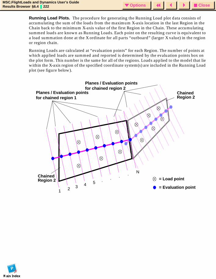
CloseOptionsMSC.FlightLoads and Dynamics User’s GuideResults Browser §6.4 222 Options
Running Load Plots. The procedure for generating the Running Load plot data consists of accumulating the sum of the loads from the maximum X-axis location in the last Region in the Chain back to the minimum X-axis value of the first Region in the Chain. These accumulating summed loads are known as Running Loads. Each point on the resulting curve is equivalent to a load summation done at the X ordinate for all parts “outboard” (larger X value) in the region or region chain.
Running Loads are calculated at “evaluation points” for each Region. The number of points at which applied loads are summed and reported is determined by the evaluation points box on the plot form. This number is the same for all of the regions. Loads applied to the model that lie within the X-axis region of the specified coordinate system(s) are included in the Running Load plot (see figure below).
Planes / Evaluation points
= Load pointChained
ChainedRegion 2for chained region 1
N....54321
Region 2
= Evaluation point
Planes / Evaluation pointsfor chained region 2
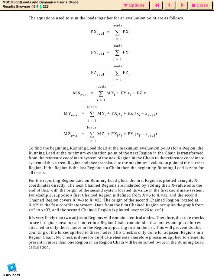
CloseOptionsMSC.FlightLoads and Dynamics User’s GuideResults Browser §6.4 223 Options
The equations used to sum the loads together for an evaluation point are as follows.
To find the beginning Running Load (load at the maximum evaluation point) for a Region, the Running Load at the minimum evaluation point of the next Region in the Chain is transformed from the reference coordinate system of the next Region in the Chain to the reference coordinate system of the current Region and then translated to the maximum evaluation point of the current Region. If the Region is the last Region in a Chain then the beginning Running Load is zero for all terms.
For the reporting Region data on Running Load plots, the first Region is plotted using its X-coordinates directly. The next Chained Regions are included by adding their X-value onto the end of this, with the origin of the second system located its value in the first coordinate system. For example, suppose a first Chained Region is defined from X’=5 to X’=32, and the second Chained Region covers X’’=-3 to X’’=23. The origin of the second Chained Region located at X’=29 in the first coordinate system. Data from the first Chained Region occupies the graph from x=5 to x=32, and the second Chained Region is plotted over x=26 to x=51.
It is very likely that two adjacent Regions will contain identical nodes. Therefore, the code checks to see if regions next to each other in a Region Chain contain identical nodes and place forces attached to only those nodes in the Region appearing first in the list. This will prevent double counting of the forces applied to these nodes. This check is only done for adjacent Regions in a Region Chain. No check is done for duplicate elements, therefore pressures applied to elements present in more than one Region in an Region Chain will be summed twice in the Running Load calculation.
FXeval FXi
i 1=
loads
∑=
FYeval FYi
i 1=
loads
∑=
FZeval FZi
i 1=
loads
∑=
MXeval MXi FYizi FZiyi+ +
i 1=
loads
∑=
MYeval MYi FXizi FZi xi xeval–( )+ +
i 1=
loads
∑=
MZeval MZi FXiyi FYi xi xeval–( )+ +
i 1=
loads
∑=
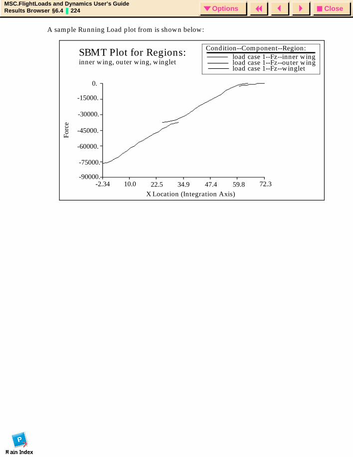
CloseOptionsMSC.FlightLoads and Dynamics User’s GuideResults Browser §6.4 224 Options
A sample Running Load plot from is shown below:
SBMT Plot for Regions:inner wing, outer wing, winglet
Condition--Component--Region:load case 1--Fz--inner wingload case 1--Fz--outer wingload case 1--Fz--winglet
Forc
e
X Location (Integration Axis)-2.34 10.0 22.5 34.9 47.4 59.8 72.3
-90000.
-75000.
-60000.
-45000.
-30000.
-15000.
0.
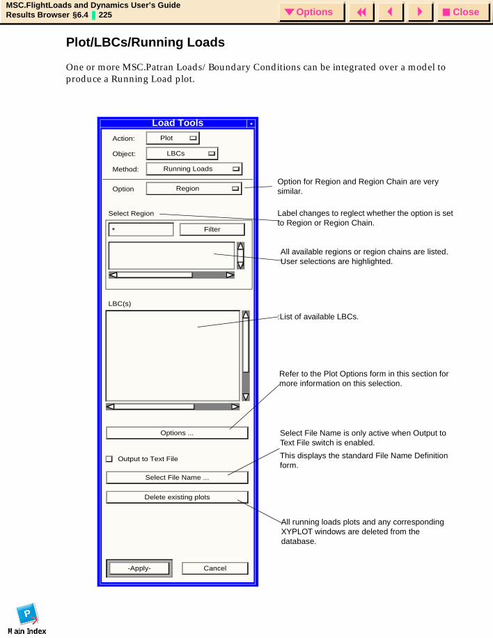
CloseOptionsMSC.FlightLoads and Dynamics User’s GuideResults Browser §6.4 225 Options
Plot/LBCs/Running Loads
One or more MSC.Patran Loads/Boundary Conditions can be integrated over a model to produce a Running Load plot.
Load Tools
Action: Plot
Object: LBCs
Method: Running Loads
Option Region
Select Region
* Filter
LBC(s)
Options ...
Output to Text File
Select File Name ...
Delete existing plots
-Apply- Cancel
Select File Name is only active when Output to Text File switch is enabled.
This displays the standard File Name Definition form.
Refer to the Plot Options form in this section for more information on this selection.
Option for Region and Region Chain are very similar.
All available regions or region chains are listed. User selections are highlighted.
All running loads plots and any corresponding XYPLOT windows are deleted from the database.
:List of available LBCs.
Label changes to reglect whether the option is set to Region or Region Chain.
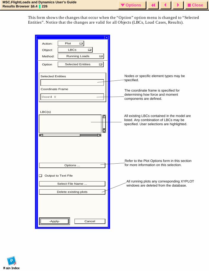
CloseOptionsMSC.FlightLoads and Dynamics User’s GuideResults Browser §6.4 226 Options
This form shows the changes that occur when the “Option” option menu is changed to “Selected Entities”. Notice that the changes are valid for all Objects (LBCs, Load Cases, Results).
Action: Plot
Object: LBCs
Method: Running Loads
Option Selected Entities
Selected Entities
Coordinate Frame
Coord 0
LBC(s)
Options ...
Output to Text File
Select File Name ...
Delete existing plots
-Apply- Cancel
Refer to the Plot Options form in this section for more information on this selection.
All running plots any corresponding XYPLOT windows are deleted from the database.
All existing LBCs contained in the model are listed. Any combination of LBCs may be specified. User selections are highlighted.
The coordinate frame is specified for determining how force and moment components are defined.
Nodes or specific element types may be specified.
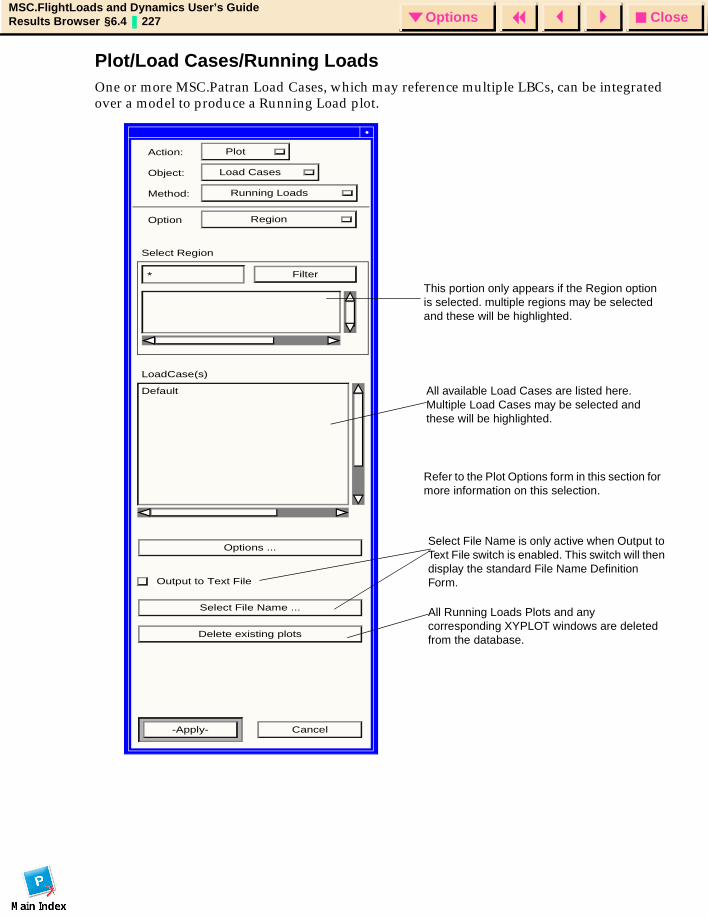
CloseOptionsMSC.FlightLoads and Dynamics User’s GuideResults Browser §6.4 227 Options
Plot/Load Cases/Running LoadsOne or more MSC.Patran Load Cases, which may reference multiple LBCs, can be integrated over a model to produce a Running Load plot.
l
Action: Plot
Object: Load Cases
Method: Running Loads
Option Region
Select Region
* Filter
LoadCase(s)
Default
Options ...
Output to Text File
Select File Name ...
Delete existing plots
-Apply- Cancel
This portion only appears if the Region option is selected. multiple regions may be selected and these will be highlighted.
All available Load Cases are listed here. Multiple Load Cases may be selected and these will be highlighted.
Select File Name is only active when Output to Text File switch is enabled. This switch will then display the standard File Name Definition Form.
Refer to the Plot Options form in this section for more information on this selection.
All Running Loads Plots and any corresponding XYPLOT windows are deleted from the database.
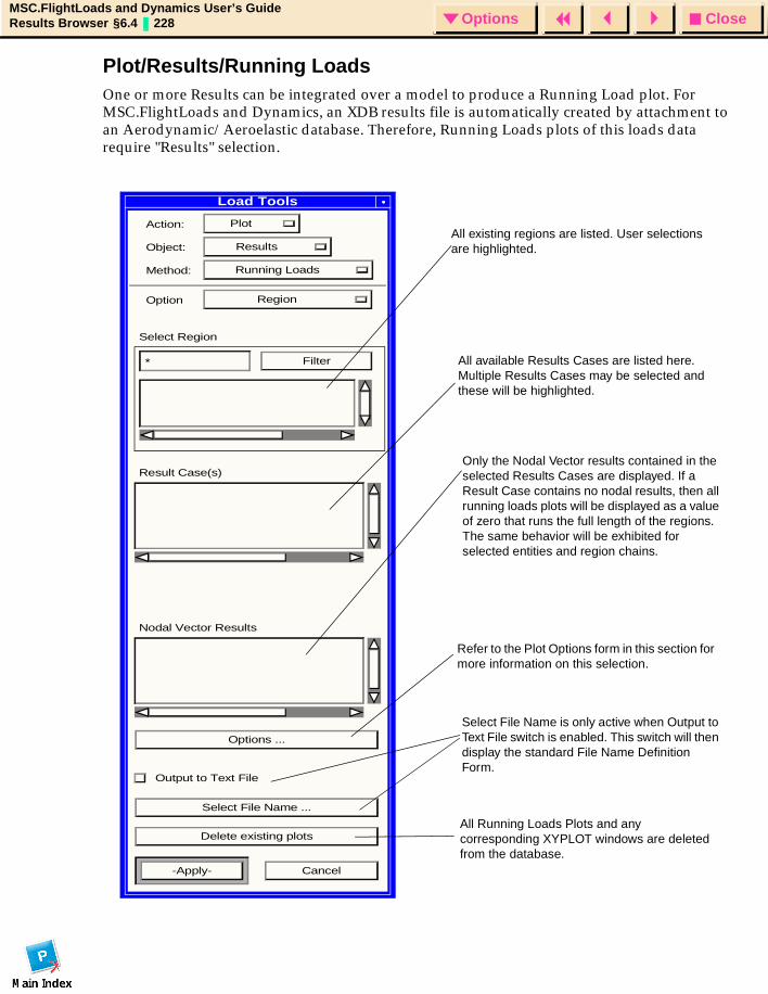
CloseOptionsMSC.FlightLoads and Dynamics User’s GuideResults Browser §6.4 228 Options
Plot/Results/Running LoadsOne or more Results can be integrated over a model to produce a Running Load plot. For MSC.FlightLoads and Dynamics, an XDB results file is automatically created by attachment to an Aerodynamic/Aeroelastic database. Therefore, Running Loads plots of this loads data require "Results" selection.
Load Tools
Action: Plot
Object: Results
Method: Running Loads
Option Region
Select Region
* Filter
Result Case(s)
Nodal Vector Results
Options ...
Output to Text File
Select File Name ...
Delete existing plots
-Apply- Cancel
All existing regions are listed. User selections are highlighted.
Only the Nodal Vector results contained in the selected Results Cases are displayed. If a Result Case contains no nodal results, then all running loads plots will be displayed as a value of zero that runs the full length of the regions. The same behavior will be exhibited for selected entities and region chains.
All available Results Cases are listed here. Multiple Results Cases may be selected and these will be highlighted.
Select File Name is only active when Output to Text File switch is enabled. This switch will then display the standard File Name Definition Form.
Refer to the Plot Options form in this section for more information on this selection.
All Running Loads Plots and any corresponding XYPLOT windows are deleted from the database.
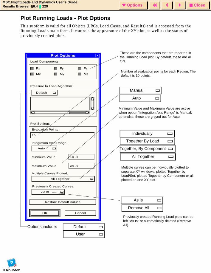
CloseOptionsMSC.FlightLoads and Dynamics User’s GuideResults Browser §6.4 229 Options
Plot Running Loads - Plot OptionsThis subform is valid for all Objects (LBCs, Load Cases, and Results) and is accessed from the Running Loads main form. It controls the appearance of the XY plot, as well as the status of previously created plots.
Plot Options
Load Components
Fx Fy Fz
Mx My Mz
Pressure to Load Algorithm
Default
Plot Settings
Evaluation Points
10
Integration Axis Range:
Auto
Minimum Value 10.0
Maximum Value 20.0
Multiple Curves Plotted:
All Together
Previously Created Curves:
As Is
Restore Default Values
OK Cancel
Individually
These are the components that are reported in the Running Load plot. By default, these are all ON.
Number of evaluation points for each Region. The default is 10 points.
Minimum Value and Maximum Value are active when option “Integration Axis Range” is Manual; otherwise, these are greyed out for Auto.
Manual
Auto
Together By Load
Together, By Component
All Together
Multiple curves can be Individually plotted to separate XY windows, plotted Together by Load/Set, plotted Together by Component or all plotted on one XY plot.
Previously created Running Load plots can be left "As Is" or automatically deleted (Remove All).
As is
Remove All
User
DefaultOptions include:
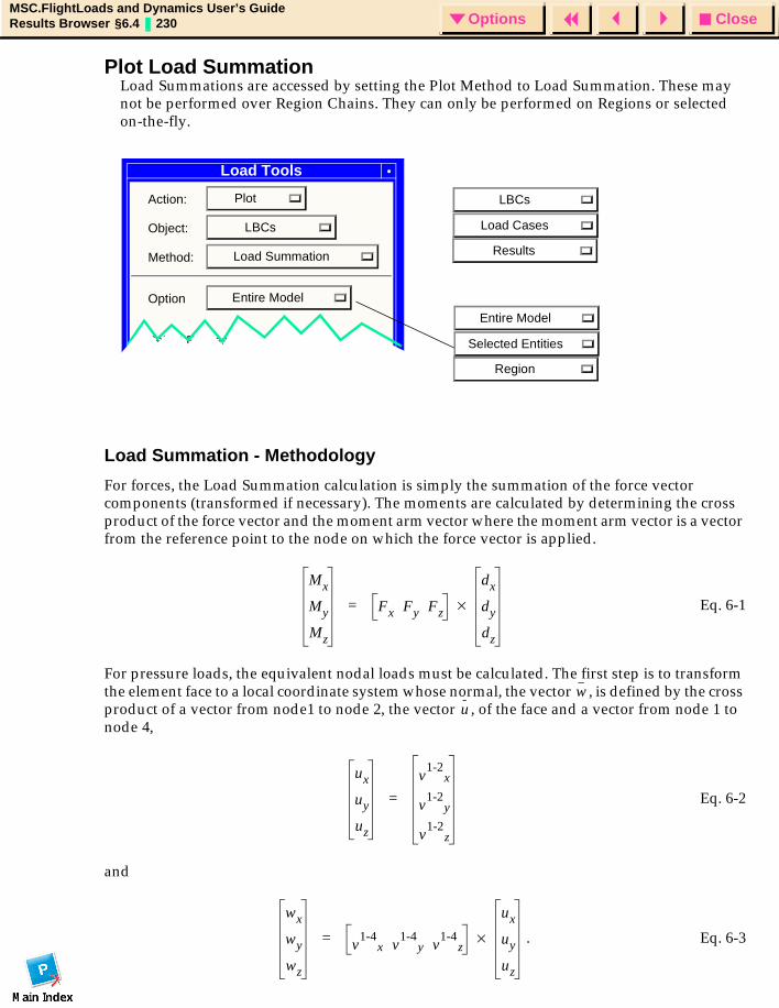
CloseOptionsMSC.FlightLoads and Dynamics User’s GuideResults Browser §6.4 230 Options
Plot Load Summation
Load Summation - Methodology
For forces, the Load Summation calculation is simply the summation of the force vector components (transformed if necessary). The moments are calculated by determining the cross product of the force vector and the moment arm vector where the moment arm vector is a vector from the reference point to the node on which the force vector is applied.
Eq. 6-1
For pressure loads, the equivalent nodal loads must be calculated. The first step is to transform the element face to a local coordinate system whose normal, the vector , is defined by the cross product of a vector from node1 to node 2, the vector , of the face and a vector from node 1 to node 4,
Eq. 6-2
and
. Eq. 6-3
Load Tools
Action: Plot
Object: LBCs
Method: Load Summation
Option Entire Model
Select Entities
Region
Selected Entities
Load Summations are accessed by setting the Plot Method to Load Summation. These may not be performed over Region Chains. They can only be performed on Regions or selected on-the-fly.
Entire Model
Results
Load Cases
LBCs
Mx
My
Mz
Fx Fy Fz
dx
dy
dz
×=
wu
ux
uy
uz
v1-2
x
v1-2
y
v1-2
z
=
wx
wy
wz
v1-4
x v1-4
y v1-4
z
ux
uy
uz
×=
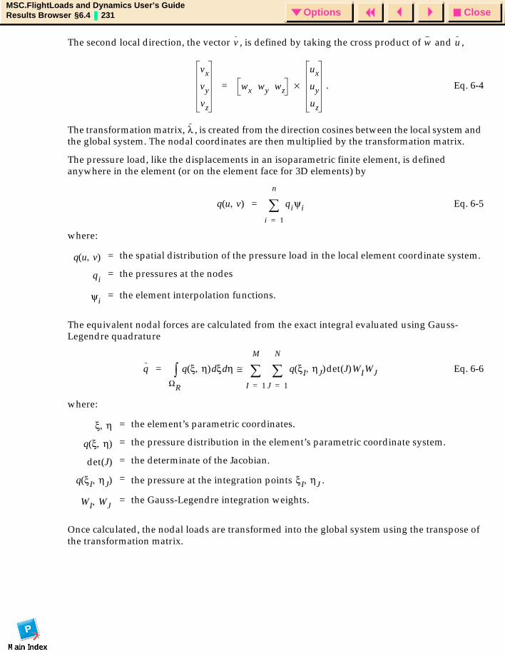
CloseOptionsMSC.FlightLoads and Dynamics User’s GuideResults Browser §6.4 231 Options
The second local direction, the vector , is defined by taking the cross product of and ,
. Eq. 6-4
The transformation matrix, , is created from the direction cosines between the local system and the global system. The nodal coordinates are then multiplied by the transformation matrix.
The pressure load, like the displacements in an isoparametric finite element, is defined anywhere in the element (or on the element face for 3D elements) by
Eq. 6-5
where:
The equivalent nodal forces are calculated from the exact integral evaluated using Gauss-Legendre quadrature
Eq. 6-6
where:
Once calculated, the nodal loads are transformed into the global system using the transpose of the transformation matrix.
= the spatial distribution of the pressure load in the local element coordinate system.
= the pressures at the nodes
= the element interpolation functions.
= the element’s parametric coordinates.
= the pressure distribution in the element’s parametric coordinate system.
= the determinate of the Jacobian.
= the pressure at the integration points .
= the Gauss-Legendre integration weights.
v w u
vx
vy
vz
wx wy wz
ux
uy
uz
×=
λ
q u v,( ) qiψi
i 1=
n
∑=
q u v,( )
qi
ψi
q q ξ η,( ) ξd ηd
ΩR
∫ q ξI ηJ,( )det J( )WIWJ
J 1=
N
∑I 1=
M
∑≅=
ξ η,
q ξ η,( )
det J( )
q ξI ηJ,( ) ξI ηJ,
WI WJ,
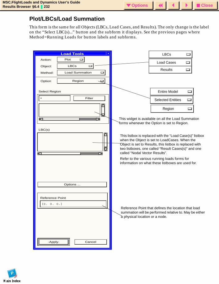
CloseOptionsMSC.FlightLoads and Dynamics User’s GuideResults Browser §6.4 232 Options
Plot/LBCs/Load SummationThis form is the same for all Objects (LBCs, Load Cases, and Results). The only change is the label on the “Select LBC(s)...” button and the subform it displays. See the previous pages where Method=Running Loads for button labels and subforms.
Action: Plot
Object: LBCs
Method: Load Summation
Option Region
Select Region
* Filter
LBC(s)
Options ...
Reference Point
-Apply- Cancel
Load Tools
[0. 0. 0.]
Entire Model
Selected Entities
LBCs
Load Cases
Results
Region
This widget is available on all the Load Summation forms whenever the Option is set to Region.
This listbox is replaced with the “Load Case(s)” listbox when the Object is set to LoadCases. When the Object is set to Results, this listbox is replaced with two listboxes, one called “Result Cases(s)” and one called “Nodal Vector Results”.
Refer to the various running loads forms for information on what these listboxes are used for.
Reference Point that defines the location that load summation will be performed relative to. May be either a physical location or a node.
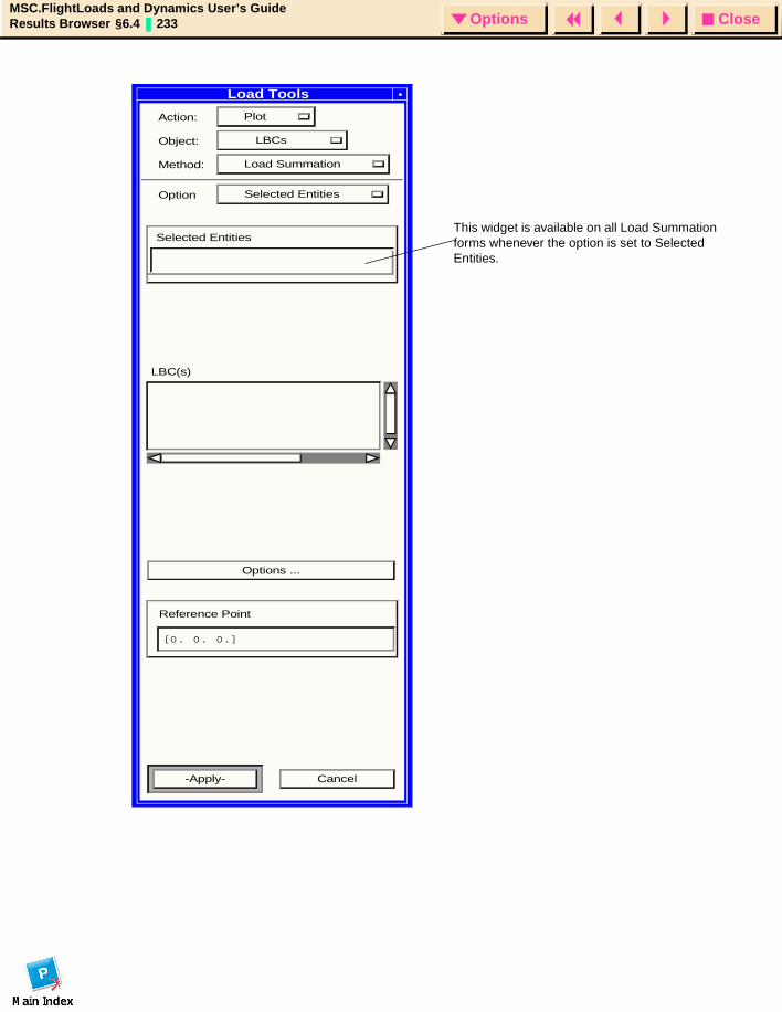
CloseOptionsMSC.FlightLoads and Dynamics User’s GuideResults Browser §6.4 233 Options
Action: Plot
Object: LBCs
Method: Load Summation
Option Selected Entities
Selected Entities
LBC(s)
Options ...
Reference Point
-Apply- Cancel
[0. 0. 0.]
This widget is available on all Load Summation forms whenever the option is set to Selected Entities.
Load Tools
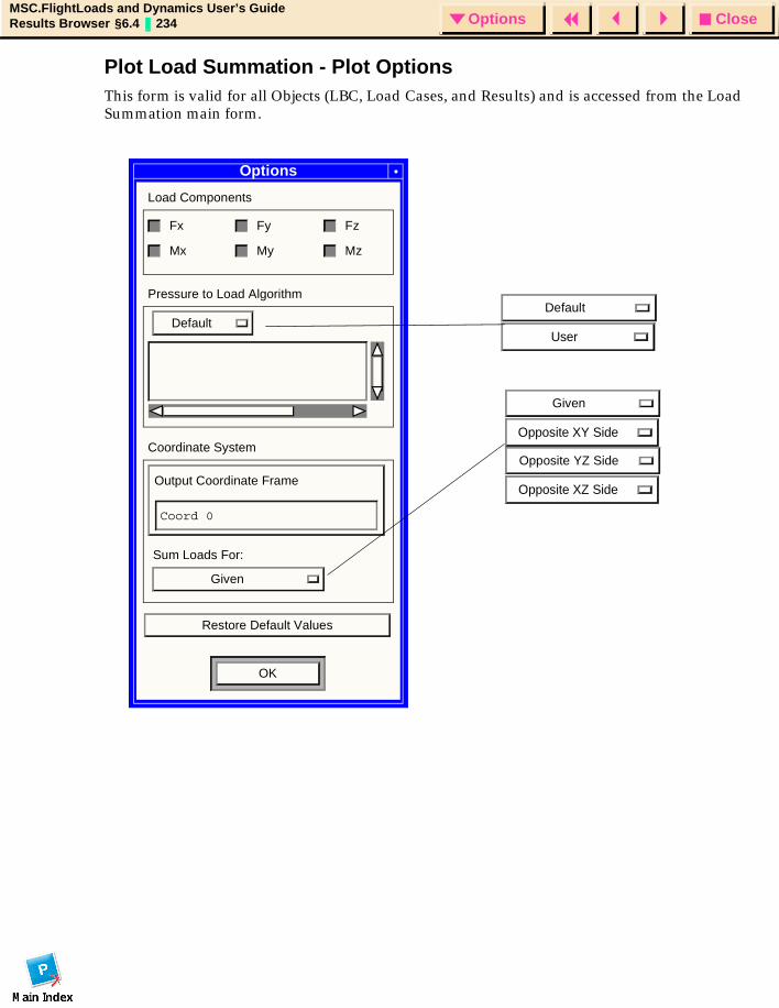
CloseOptionsMSC.FlightLoads and Dynamics User’s GuideResults Browser §6.4 234 Options
Plot Load Summation - Plot OptionsThis form is valid for all Objects (LBC, Load Cases, and Results) and is accessed from the Load Summation main form.
Options
Load Components
Fx Fy Fz
Mx My Mz
Pressure to Load Algorithm
Default
Coordinate System
Output Coordinate Frame
Coord 0
Sum Loads For:
Given
Restore Default Values
OK
Default
User
Given
Opposite XY Side
Opposite YZ Side
Opposite XZ Side
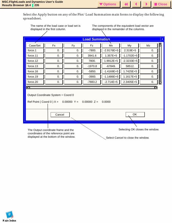
CloseOptionsMSC.FlightLoads and Dynamics User’s GuideResults Browser §6.4 235 Options
Select the Apply button on any of the Plot/Load Summation main forms to display the following spreadsheet.
Load Summation
The name of the load case or load set is displayed in the first column.
The components of the equivalent load vector are displayed in the remainder of the columns.
The Output coordinate frame and the coordinates of the reference point are displayed at the bottom of the window.
Selecting OK closes the window.
Case/Set Fx Fy Fz Mx My Mz
force.1
force.11
force.12
force.13
force.16
force.19
force.20
0.
0.
0.
0.
0.
0.
0.
0.
0.
0.
0.
0.
0.
0.
0.
0.
0.
0.
0.
0.
0.
-7800.
3941.6
7800.
-1970.8
-5850.
-3900.
-7883.2
-2.9176E+5
1.357E+5
1.9912E+5
-67849.
-1.4169E+5
-1.1486E+5
-2.714E+5
2.319E+5
-1.1702E+5
-2.3233E+5
58512.
1.7425E+5
1.1617E+5
2.3405E+5
Output Coordinate System = Coord 0
Ref Point ( Coord 0 ) X = 0.00000 Y = 0.00000 Z = 0.0000
OK Cancel
Select Cancel to close the window.
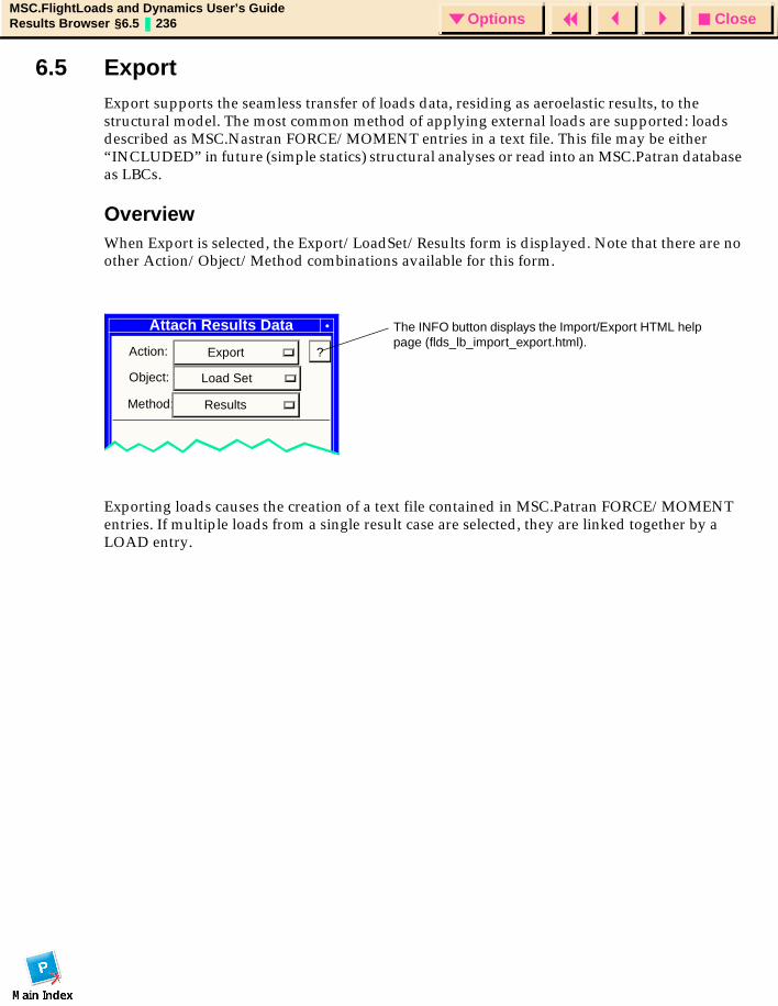
CloseOptionsMSC.FlightLoads and Dynamics User’s GuideResults Browser §6.5 236 Options
6.5 Export Export supports the seamless transfer of loads data, residing as aeroelastic results, to the structural model. The most common method of applying external loads are supported: loads described as MSC.Nastran FORCE/MOMENT entries in a text file. This file may be either “INCLUDED” in future (simple statics) structural analyses or read into an MSC.Patran database as LBCs.
OverviewWhen Export is selected, the Export/LoadSet/Results form is displayed. Note that there are no other Action/Object/Method combinations available for this form.
Exporting loads causes the creation of a text file contained in MSC.Patran FORCE/MOMENT entries. If multiple loads from a single result case are selected, they are linked together by a LOAD entry.
Attach Results Data
Action: Export
Object: Load Set
Method: Results
The INFO button displays the Import/Export HTML help page (flds_lb_import_export.html).
?
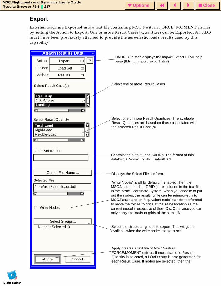
CloseOptionsMSC.FlightLoads and Dynamics User’s GuideResults Browser §6.5 237 Options
ExportExternal loads are Exported into a text file containing MSC.Nastran FORCE/MOMENT entries by setting the Action to Export. One or more Result Cases/Quantities can be Exported. An XDB must have been previously attached to provide the aeroelastic loads results used by this capability.
Attach Results Data
Action: Export
Object: Load Set
Output File Name ...
-Apply- Cancel
Method: Results
Select Result Case(s)
Select Result Quantity
6g-Pullup1.0g-Cruise Landing
Total-LoadRigid-LoadFlexible-Load
Apply creates a text file of MSC.Nastran FORCE/MOMENT entries. If more than one Result Quantity is selected, a LOAD entry is also generated for each Result Case. If nodes are selected, then the
Write Nodes
“Write Nodes” is off by default. If enabled, then the MSC.Nastran nodes (GRIDs) are included in the text file in the Basic Coordinate System. When you choose to put out the nodes, the resulting file can be reimported into MSC.Patran and an “equivalent node” transfer performed to move the forces to grids at the same location as the current model irrespective of their ID’s. Otherwise you can only apply the loads to grids of the same ID.
Select one or more Result Cases.
Select one or more Result Quantities. The available Result Quantities are based on those associated with the selected Result Case(s).
Controls the output Load Set IDs. The format of this databox is "From: To: By". Default is 1.
Load Set ID List
Selected File:
6g-Pullup/aero/user/smith/loads.bdf
?
Displays the Select File subform.
The INFO button displays the Import/Export HTML help page (flds_lb_import_export.html).
Select Groups...Select the structural groups to export. This widget is available when the write nodes toggle is set.
Number Selected: 0
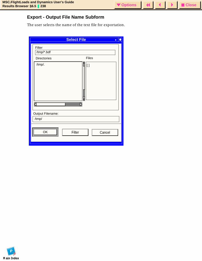
CloseOptionsMSC.FlightLoads and Dynamics User’s GuideResults Browser §6.5 238 Options
Export - Output File Name Subform
The user selects the name of the text file for exportation.
Select File
Filter/tmp/*.bdf
Directories Files
/tmp/. [ ]
/tmp/
Output Filename:
OK CancelFilter

CloseOptionsMSC.FlightLoads and Dynamics User’s GuideResults Browser §6.6 239 Options
6.6 Results ViewerThis button displays the MSC.Patran Results forms using the Flexible Increment Filter to filter through the available results when requested.

CloseOptionsMSC.FlightLoads and Dynamics User’s GuideResults Browser §6.6 240 Options

CloseOptionsMSC.FlightLoads and Dynamics User’s GuideImport/Export § 241 Options
MSC.FlightLoads and Dynamics User’s Guide
CHAPTER
7 Import/Export
MSC.FlightLoads and Dynamics User’s Guide
Introduction
Import
Export
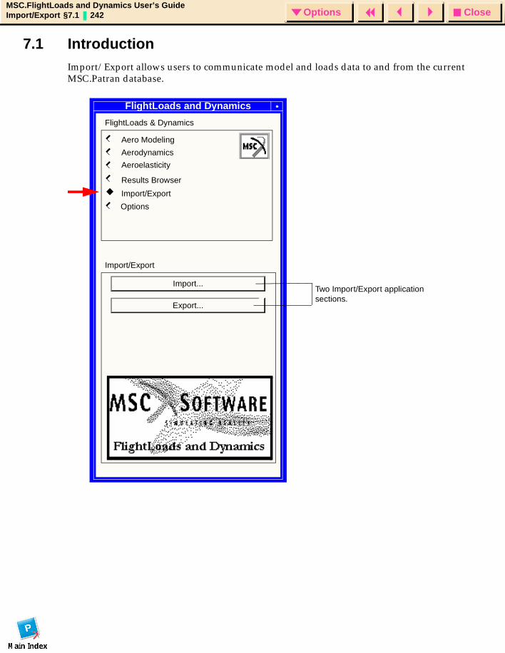
CloseOptionsMSC.FlightLoads and Dynamics User’s GuideImport/Export §7.1 242 Options
7.1 IntroductionImport/Export allows users to communicate model and loads data to and from the current MSC.Patran database.
MSC/FL&DSFlightLoads and Dynamics
FlightLoads & Dynamics
Aero Modeling
Aerodynamics
Aeroelasticity
Results Browser
Import/Export
Import/Export
Import...
Export...
Two Import/Export application sections.
Options
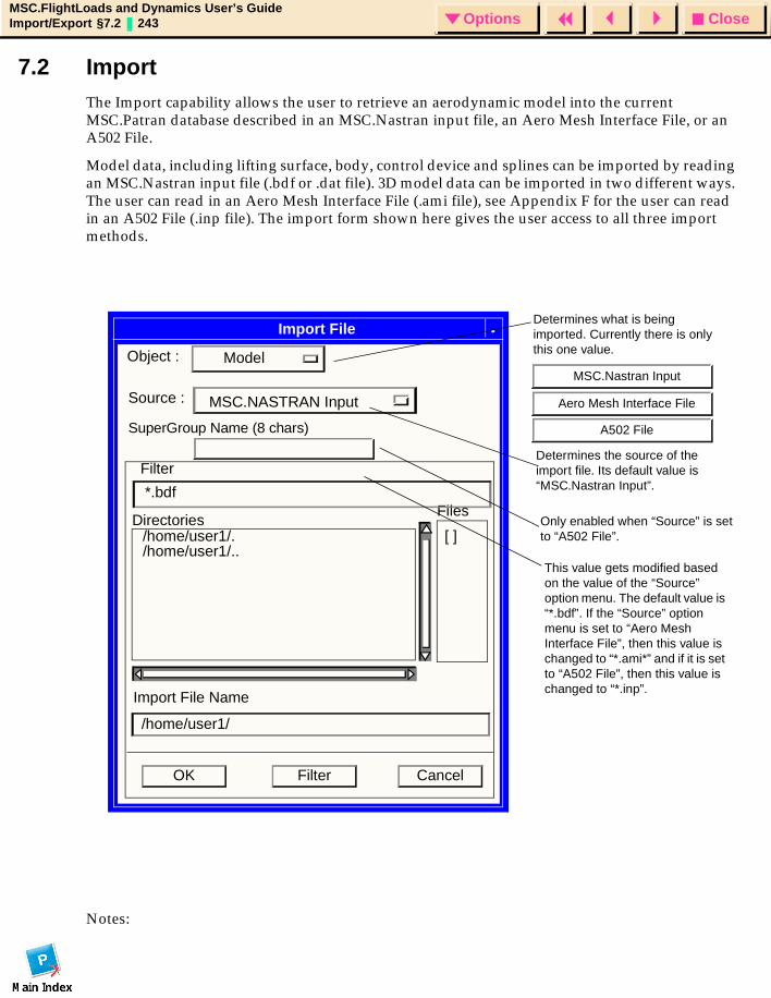
CloseOptionsMSC.FlightLoads and Dynamics User’s GuideImport/Export §7.2 243 Options
7.2 ImportThe Import capability allows the user to retrieve an aerodynamic model into the current MSC.Patran database described in an MSC.Nastran input file, an Aero Mesh Interface File, or an A502 File.
Model data, including lifting surface, body, control device and splines can be imported by reading an MSC.Nastran input file (.bdf or .dat file). 3D model data can be imported in two different ways. The user can read in an Aero Mesh Interface File (.ami file), see Appendix F for the user can read in an A502 File (.inp file). The import form shown here gives the user access to all three import methods.
Notes:
Import File
CancelOK Filter
DirectoriesFiles
[ ]
Import File Name
Filter
*.bdf
/home/user1/./home/user1/..
/home/user1/
ModelObject :
MSC.NASTRAN InputSource :
This value gets modified based on the value of the “Source” option menu. The default value is “*.bdf”. If the “Source” option menu is set to “Aero Mesh Interface File”, then this value is changed to “*.ami*” and if it is set to “A502 File”, then this value is changed to “*.inp”.
Determines what is being imported. Currently there is only this one value.
MSC.Nastran Input
A502 File
Aero Mesh Interface File
SuperGroup Name (8 chars)
Only enabled when “Source” is set to “A502 File”.
Determines the source of the import file. Its default value is “MSC.Nastran Input”.
CloseOptionsMSC.FlightLoads and Dynamics User’s GuideImport/Export §7.2 244 Options
1. Upon reading in a MSC.Nastran input file, the appropriate entities are created in the database as if the user had performed the construction via the user interface. The appropriate session file commands mimicking this construction are created.
2. The aerodynamic coordinate system from the bulk data file as well as hinge line coordinate systems are copied into the MSC.Patran database. However, if a coordinate system of the same ID is already in the database, it is assumed that this coordinate system is to be used and the one from the bulk data file is not imported.
3. For the spline information to be imported, the structural nodes must already exist in the database. If you are importing both the structural and aerodynamic models into the database, you must import the structure first (using the File/Import option of the MSC.Patran Structural Preference) before using the MSC.FlightLoads Import option to obtain the aerodynamic model. If the structural nodes are not present, the aerodynamic model is imported but not the aeroelastic model.
4. Importing of 3D model data causes the appropriate entities to be created in the database. Currently, there is no user interface to allow the users to create 3D models from scratch so no commands are written to the session file.
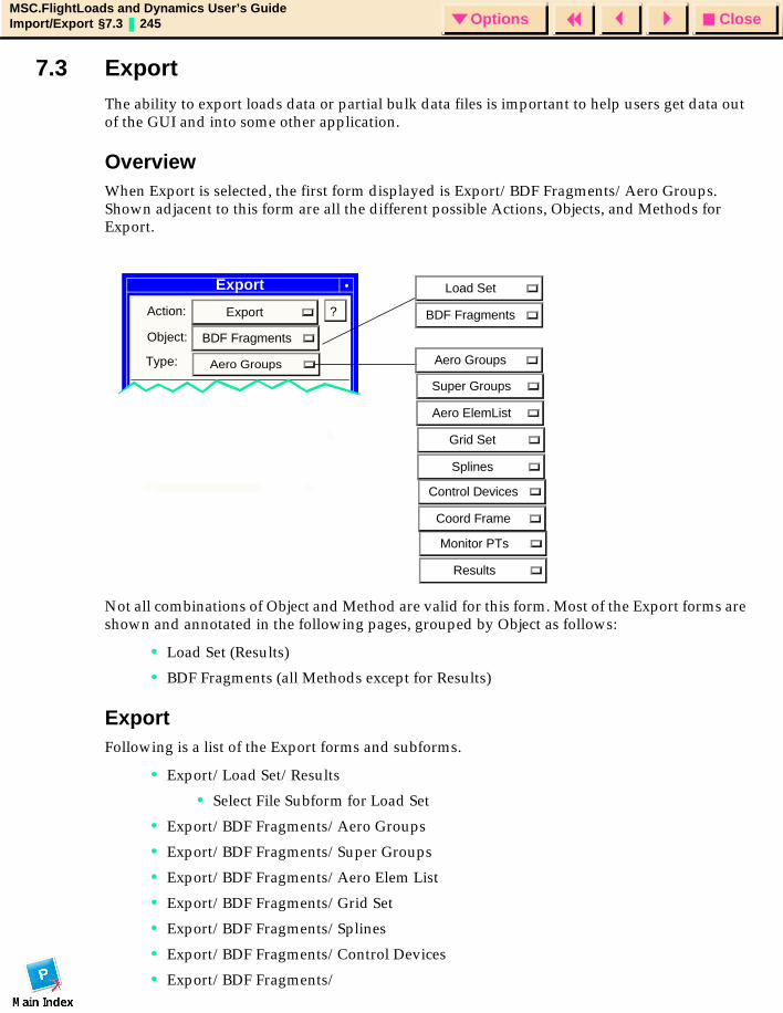
CloseOptionsMSC.FlightLoads and Dynamics User’s GuideImport/Export §7.3 245 Options
7.3 ExportThe ability to export loads data or partial bulk data files is important to help users get data out of the GUI and into some other application.
OverviewWhen Export is selected, the first form displayed is Export/BDF Fragments/Aero Groups. Shown adjacent to this form are all the different possible Actions, Objects, and Methods for Export.
Not all combinations of Object and Method are valid for this form. Most of the Export forms are shown and annotated in the following pages, grouped by Object as follows:
• Load Set (Results)
• BDF Fragments (all Methods except for Results)
Export Following is a list of the Export forms and subforms.
• Export/Load Set/Results
• Select File Subform for Load Set
• Export/BDF Fragments/Aero Groups
• Export/BDF Fragments/Super Groups
• Export/BDF Fragments/Aero Elem List
• Export/BDF Fragments/Grid Set
• Export/BDF Fragments/Splines
• Export/BDF Fragments/Control Devices
• Export/BDF Fragments/
Export
Action: Export
Object: BDF Fragments
Type: Aero Groups
Landing
Total-Load
?
Load Set
BDF Fragments
Aero Groups
Super Groups
Aero ElemList
Grid Set
Splines
Monitor PTs
Results
Control Devices
Coord Frame

CloseOptionsMSC.FlightLoads and Dynamics User’s GuideImport/Export §7.3 246 Options
• Export/BDF Fragments/Monitor Points
• Select File Subform for BDF Fragments
• Select Surface/Select Groups Subform
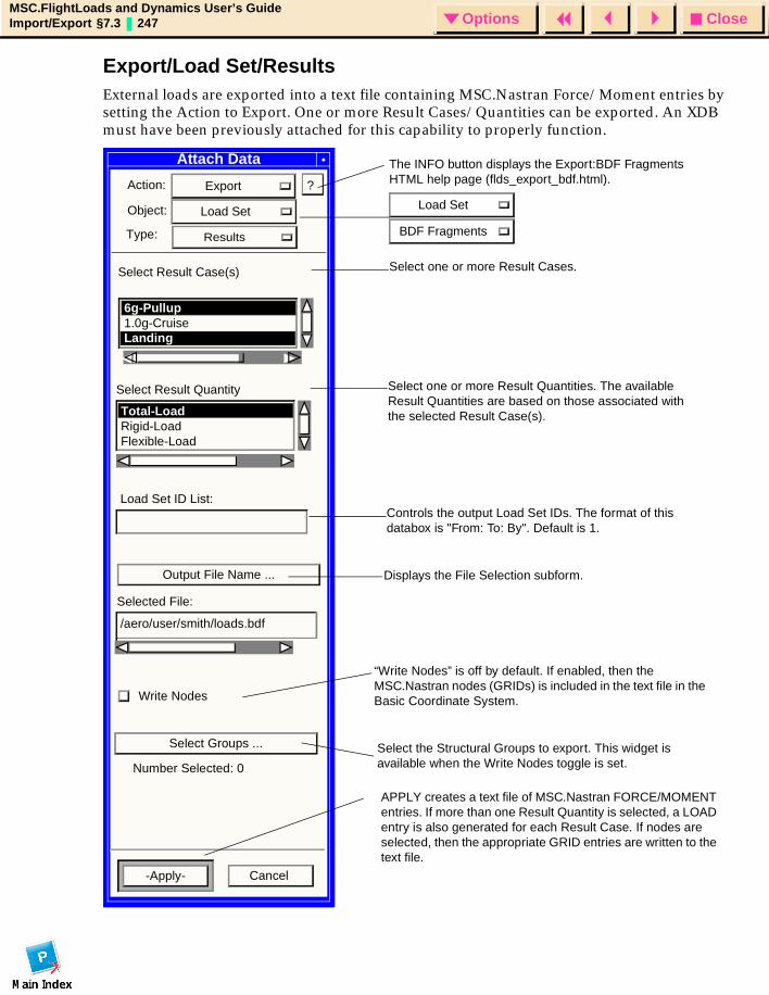
CloseOptionsMSC.FlightLoads and Dynamics User’s GuideImport/Export §7.3 247 Options
Export/Load Set/ResultsExternal loads are exported into a text file containing MSC.Nastran Force/Moment entries by setting the Action to Export. One or more Result Cases/Quantities can be exported. An XDB must have been previously attached for this capability to properly function.
Attach Data
Action: Export
Object: Load Set
Output File Name ...
-Apply- Cancel
Type: Results
Select Result Case(s)
Select Result Quantity
6g-Pullup1.0g-Cruise Landing
Total-LoadRigid-LoadFlexible-Load
APPLY creates a text file of MSC.Nastran FORCE/MOMENT entries. If more than one Result Quantity is selected, a LOAD entry is also generated for each Result Case. If nodes are selected, then the appropriate GRID entries are written to the text file.
Write Nodes
“Write Nodes” is off by default. If enabled, then the MSC.Nastran nodes (GRIDs) is included in the text file in the Basic Coordinate System.
Select one or more Result Cases.
Select one or more Result Quantities. The available Result Quantities are based on those associated with the selected Result Case(s).
Controls the output Load Set IDs. The format of this databox is "From: To: By". Default is 1.
Load Set ID List:
Selected File:
6g-Pullup/aero/user/smith/loads.bdf
?
The INFO button displays the Export:BDF Fragments HTML help page (flds_export_bdf.html).
Displays the File Selection subform.
Load Set
BDF Fragments
Select Groups ...
Number Selected: 0
Select the Structural Groups to export. This widget is available when the Write Nodes toggle is set.

CloseOptionsMSC.FlightLoads and Dynamics User’s GuideImport/Export §7.3 248 Options
Select File Subform
The user selects the name of the text file for exportation from the following.
Select File
Filter/tmp/*.bdf
Directories Files
/tmp/.
/tmp/
Output Filename:
OK CancelFilter

CloseOptionsMSC.FlightLoads and Dynamics User’s GuideImport/Export §7.3 249 Options
BDF FragmentsThe Export of BDF Fragments allows you to select certain data from FlightLoads to be exported to a text file in MSC.Nastran Bulk Data File format. These "fragments" of BDF files allow access to commonly needed portions of models without requiring you to create a subcase and job.
This form is exercised by naming a file and repetitively selecting instances of the various "Method" types. The file will initially default to "Overwrite" status and, following the first pick, will change to "Append" status.
Thus, repetitive "Apply" actions on selections will append to the named file by default. The default can be overridden by explicit selection.
When the selected item requires that more than one BDF entry be created (for example, SPLINE4 refers to an AELIST and SET1 entry), the dependent entries will automatically be created.
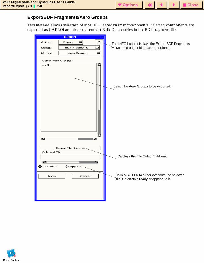
CloseOptionsMSC.FlightLoads and Dynamics User’s GuideImport/Export §7.3 250 Options
Export/BDF Fragments/Aero Groups
This method allows selection of MSC.FLD aerodynamic components. Selected components are exported as CAEROi and their dependent Bulk Data entries in the BDF fragment file.
Export
Action: Export
Object: BDF Fragments
Method: Aero Groups
Select Aero Group(s)
surf1
Output File Name ...
Selected File:
Overwrite Append
Apply Cancel
?
Select the Aero Groups to be exported.
Tells MSC.FLD to either overwrite the selected file it is exists already or append to it.
Displays the File Select Subform.
The INFO button displays the Export:BDF Fragments HTML help page (flds_export_bdf.html).
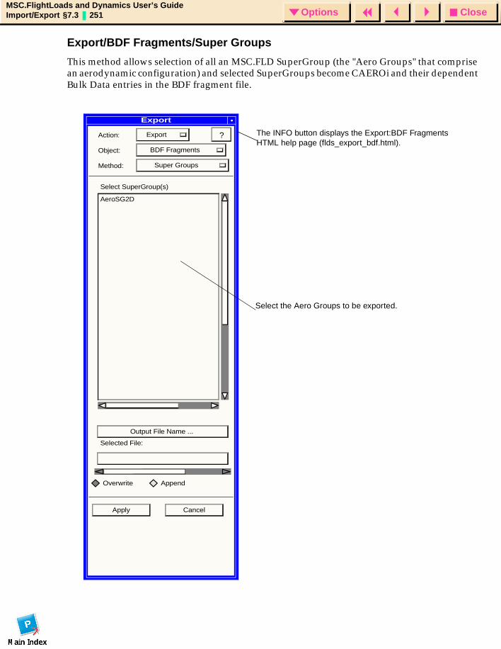
CloseOptionsMSC.FlightLoads and Dynamics User’s GuideImport/Export §7.3 251 Options
Export/BDF Fragments/Super Groups
This method allows selection of all an MSC.FLD SuperGroup (the "Aero Groups" that comprise an aerodynamic configuration) and selected SuperGroups become CAEROi and their dependent Bulk Data entries in the BDF fragment file.
Action: Export
Object: BDF Fragments
Method: Super Groups
Select SuperGroup(s)
AeroSG2D
Output File Name ...
Selected File:
Overwrite Append
Apply Cancel
? The INFO button displays the Export:BDF Fragments HTML help page (flds_export_bdf.html).
Select the Aero Groups to be exported.
Export
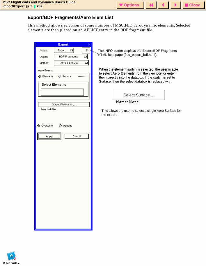
CloseOptionsMSC.FlightLoads and Dynamics User’s GuideImport/Export §7.3 252 Options
Export/BDF Fragments/Aero Elem List
This method allows selection of some number of MSC.FLD aerodynamic elements. Selected elements are then placed on an AELIST entry in the BDF fragment file.
Export
Action: Export
Object: BDF Fragments
Method: Aero Elem List
Aero Boxes
Elements Surface
Output File Name ...
Selected File:
Overwrite Append
Apply Cancel
? The INFO button displays the Export:BDF Fragments HTML help page (flds_export_bdf.html).
Select Elements
This allows the user to select a single Aero Surface for the export.
When the element switch is selected, the user is able to select Aero Elements from the view port or enter them directly into the databox. If the switch is set to Surface, then the select databox is replaced with:
Select Surface ...
Name: None
When the element switch is selected, the user is able to select Aero Elements from the view port or enter them directly into the databox. If the switch is set to Surface, then the select databox is replaced with:
Name: None
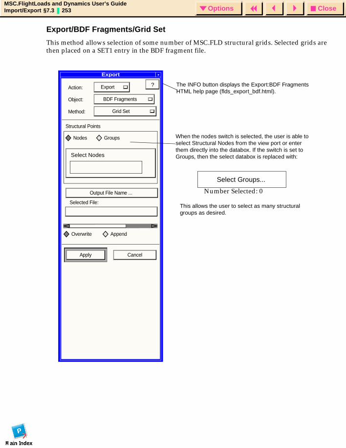
CloseOptionsMSC.FlightLoads and Dynamics User’s GuideImport/Export §7.3 253 Options
Export/BDF Fragments/Grid Set
This method allows selection of some number of MSC.FLD structural grids. Selected grids are then placed on a SET1 entry in the BDF fragment file.
Export
Action: Export
Object: BDF Fragments
Method: Grid Set
Structural Points
Nodes Groups
Output File Name ...
Selected File:
Overwrite Append
Apply Cancel
? The INFO button displays the Export:BDF Fragments HTML help page (flds_export_bdf.html).
This allows the user to select as many structural groups as desired.
Select Groups...
When the nodes switch is selected, the user is able to select Structural Nodes from the view port or enter them directly into the databox. If the switch is set to Groups, then the select databox is replaced with:
Number Selected: 0
Select Nodes
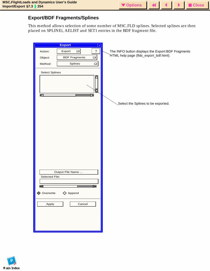
CloseOptionsMSC.FlightLoads and Dynamics User’s GuideImport/Export §7.3 254 Options
Export/BDF Fragments/Splines
This method allows selection of some number of MSC.FLD splines. Selected splines are then placed on SPLINEi, AELIST and SET1 entries in the BDF fragment file.
Action: Export
Object: BDF Fragments
Method: Splines
Select Splines
Output File Name ...
Selected File:
Overwrite Append
Apply Cancel
? The INFO button displays the Export:BDF Fragments HTML help page (flds_export_bdf.html).
Select the Splines to be exported.
Export
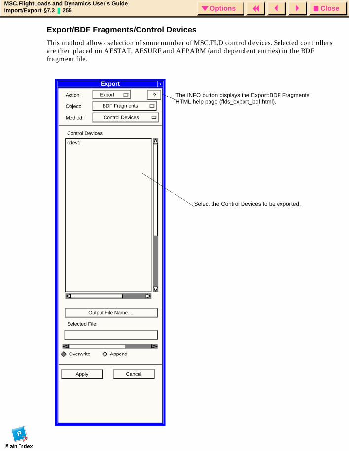
CloseOptionsMSC.FlightLoads and Dynamics User’s GuideImport/Export §7.3 255 Options
Export/BDF Fragments/Control Devices
This method allows selection of some number of MSC.FLD control devices. Selected controllers are then placed on AESTAT, AESURF and AEPARM (and dependent entries) in the BDF fragment file.
Export
Action: Export
Object: BDF Fragments
Method: Control Devices
Control Devices
cdev1
Selected File:
Overwrite Append
Apply Cancel
? The INFO button displays the Export:BDF Fragments HTML help page (flds_export_bdf.html).
Select the Control Devices to be exported.
Output File Name ...
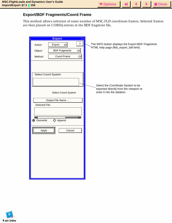
CloseOptionsMSC.FlightLoads and Dynamics User’s GuideImport/Export §7.3 256 Options
Export/BDF Fragments/Coord Frame
This method allows selection of some number of MSC.FLD coordinate frames. Selected frames are then placed on CORDij entries in the BDF fragment file.
Export
Action: Export
Object: BDF Fragments
Method: Coord Frame
Select Coord System
Output File Name ...
Selected File:
Overwrite Append
Apply Cancel
? The INFO button displays the Export:BDF Fragments HTML help page (flds_export_bdf.html).
Select the Coordinate System to be exported directly from the viewport or enter it into the databox.
Select Coord System
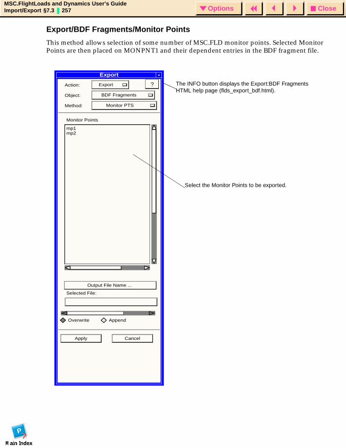
CloseOptionsMSC.FlightLoads and Dynamics User’s GuideImport/Export §7.3 257 Options
Export/BDF Fragments/Monitor Points
This method allows selection of some number of MSC.FLD monitor points. Selected Monitor Points are then placed on MONPNT1 and their dependent entries in the BDF fragment file.
Export
Action: Export
Object: BDF Fragments
Method: Monitor PTS
Monitor Points
mp1mp2
Output File Name ...
Selected File:
Overwrite Append
Apply Cancel
? The INFO button displays the Export:BDF Fragments HTML help page (flds_export_bdf.html).
Select the Monitor Points to be exported.
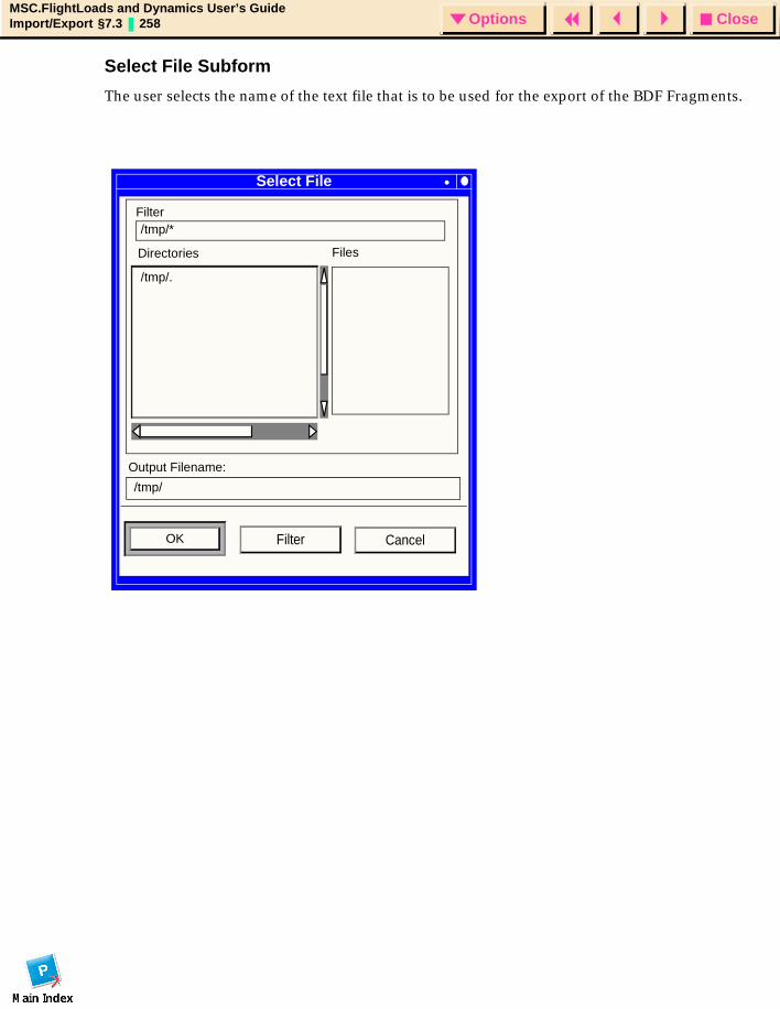
CloseOptionsMSC.FlightLoads and Dynamics User’s GuideImport/Export §7.3 258 Options
Select File Subform
The user selects the name of the text file that is to be used for the export of the BDF Fragments.
Select File
Filter/tmp/*
Directories Files
/tmp/.
/tmp/
Output Filename:
OK CancelFilter
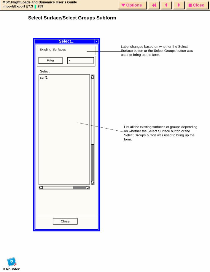
CloseOptionsMSC.FlightLoads and Dynamics User’s GuideImport/Export §7.3 259 Options
Select Surface/Select Groups Subform
Select...
Existing Surfaces
Filter *
Select
surf1
Close
Label changes based on whether the Select Surface button or the Select Groups button was used to bring up the form.
List all the existing surfaces or groups depending on whether the Select Surface button or the Select Groups button was used to bring up the form.

CloseOptionsMSC.FlightLoads and Dynamics User’s GuideImport/Export §7.3 260 Options

CloseOptionsMSC.FlightLoads and Dynamics User’s GuidePanel Aerodynamics § 261 Options
MSC.FlightLoads and Dynamics User’s Guide
APPENDIX
A Panel Aerodynamics
Introduction
Aerodynamic Data Generation
Aerodynamic Theories
Aerodynamic Modeling Guidelines
CloseOptionsMSC.FlightLoads and Dynamics User’s GuidePanel Aerodynamics § 262 Options
IntroductionMSC.FlightLoads and Dynamics Version 1 creates aerodynamic models and produces results that are compatible with the Doublet-Lattice and ZONA51 aerodynamics that are provided in MSC.Nastran. The Doublet Lattice method (DLM) is applicable to subsonic flows while ZONA51 can be considered its supersonic counterpart. These methods are of a of class "Panel Methods" that represent lifting surfaces by flat panels that are nominally parallel to the flow. The Doublet Lattice method has the additional ability to represent bodies as variable radius cylinders, also aligned with the airflow. Other "Panel Methods" can be more general and represent the surfaces as discrete curved surfaces in 3-space.
This Appendix provides a brief description and theoretical discussion of these methods and then offers some guidelines for their use. Much of this development is taken from the MSC.Nastran User’s Guide for Aeroelastic Analysis (Ref. 12) with corrections and supplementary material provided for this document.
MSC.Nastran aerodynamic analysis, like structural analysis, is based upon a finite element approach. The finite aerodynamic elements are strips or boxes on which there are aerodynamic forces. The aerodynamic elements, even for complex vehicles, must be in regular arrays. In particular, the aerodynamic elements for the lattice methods are arrays of trapezoidal boxes with sides that are parallel to the airflow. These can be described simply by defining properties of the array (panel).
Aerodynamic forces are generated when the flow is disturbed by the flexible vehicle. Theory leads to a matrix that relates the forces acting upon the structure due to the deflections of the structure.
These deflections are the combination of rigid body motions of the vehicle and the structural deformations of the vehicle as it undergoes an applied loading during a maneuver. For the steady flow considered in FlightLoads Static Aeroelastic analysis, the relationship between the deflection and the forces is a function of the aerodynamic model (including any symmetry conditions) and the Mach number of the flow.

CloseOptionsMSC.FlightLoads and Dynamics User’s GuidePanel Aerodynamics § 263 Options
Aerodynamic Data GenerationAerodynamic elements are boxes or segments of bodies that are combined to idealize the vehicle for the computation of aerodynamic forces. These elements, like structural elements, are defined by their geometry and their motions are defined by degrees of freedom at aerodynamic grid points. Requirements of the aerodynamic theory dictate the geometry of the boxes. The Doublet-Lattice (DLM) and ZONA51 methods assume trapezoidal boxes with their edges parallel to the free-stream velocity. By the use of aerodynamic input data, aerodynamic elements and grid points are automatically generated to help ensure that many of the theoretical requirements are met.
Aerodynamic calculations are performed using a Cartesian coordinate system. By the usual convention, the flow is in the positive X-direction, and the X-axis of every aerodynamic element must be parallel to the flow in its undeformed position. (This is an assumption of aerodynamic small disturbance theory.) The structural coordinate systems may be defined independently, since the use of the same system for both may place an undesirable restriction upon the description of the structural model. Any MSC.Nastran Cartesian system may be specified for the aerodynamic coordinates, with the resulting flow defined in the direction of the X-axis. All aerodynamic element and grid point data are transformed to the aerodynamic coordinate system. All the global (displacement) coordinate systems of the aerodynamic grid points will have their T1-directions in the flow direction. Their T3-directions will be normal to the element in the case of boxes, and parallel to the aerodynamic T2- and/or T3-directions in the case of bodies.
The aerodynamic grid points are physically located at the centers of the boxes for the lifting surface theories and at the centers of body elements for the DLM. A second set of grid points, used only for display, is located at the element corners. Grid point numbers are generated based upon the element identification number.
Both sets of grid points are numbered beginning with the user provided ID of the lifting surface. The centroidal grids are numbered from the inboard leading edge box and then incremented by one, first in the chordwise direction and then in the spanwise direction. The corner grid numbering begins at the leading edge inboard corner and again proceeds first chordwise and then spanwise. In terms of the graphical display, the centroidal grids can be thought of as element ID’s and corner points as node ID’s.
The aerodynamic theories in MSC.Nastran have additional downwash locations that need to be defined here. These points are designated as comprising the j-set of aerodynamic control points. The j-set is not a user set; it is a notational set to identify aerodynamic matrices used in the solution processing. Physically, these are points on the element where the downwash vectors are computed. The location of these points is a function of the aerodynamic method employed:
• For Doublet-Lattice boxes, the downwash point is at the 75% chordwise station and spanwise center of the box. The pressure singularity is computed along the 25% chordwise station.
• For ZONA51 boxes, the downwash point is at the 95% chordwise station and the spanwise center of the box while the pressure in considered constant over the element.
• For Doublet-Lattice interference and slender body elements, the control point and pressure singularity are identically located along the axis of the element and at 50% of its length.
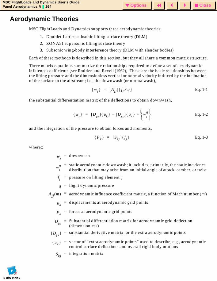
CloseOptionsMSC.FlightLoads and Dynamics User’s GuidePanel Aerodynamics § 264 Options
Aerodynamic TheoriesMSC.FlightLoads and Dynamics supports three aerodynamic theories:
1. Doublet-Lattice subsonic lifting surface theory (DLM)
2. ZONA51 supersonic lifting surface theory
3. Subsonic wing-body interference theory (DLM with slender bodies)
Each of these methods is described in this section, but they all share a common matrix structure.
Three matrix equations summarize the relationships required to define a set of aerodynamic influence coefficients [see Rodden and Revell (1962)]. These are the basic relationships between the lifting pressure and the dimensionless vertical or normal velocity induced by the inclination of the surface to the airstream; i.e., the downwash (or normalwash),
Eq. 1-1
the substantial differentiation matrix of the deflections to obtain downwash,
Eq. 1-2
and the integration of the pressure to obtain forces and moments,
Eq. 1-3
where::
= downwash
= static aerodynamic downwash; it includes, primarily, the static incidence distribution that may arise from an initial angle of attack, camber, or twist
= pressure on lifting element
= flight dynamic pressure
= aerodynamic influence coefficient matrix, a function of Mach number ( )
= displacements at aerodynamic grid points
= forces at aerodynamic grid points
= Substantial differentiation matrix for aerodynamic grid deflection (dimensionless)
= substantial derivative matrix for the extra aerodynamic points
= vector of “extra aerodynamic points” used to describe, e.g., aerodynamic control surface deflections and overall rigid body motions
= integration matrix
wj Ajj[ ] fj q⁄ =
wj Djk[ ] uk Djx[ ] ux wjg
+ +=
Pk Skj[ ] fj =
wj
wjg
fj j
q
Ajj m( ) m
uk
Pk
Djk
Djx[ ]
ux
Skj
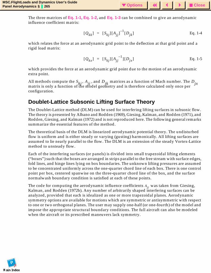
CloseOptionsMSC.FlightLoads and Dynamics User’s GuidePanel Aerodynamics § 265 Options
The three matrices of Eq. 1-1, Eq. 1-2, and Eq. 1-3 can be combined to give an aerodynamic influence coefficient matrix:
Eq. 1-4
which relates the force at an aerodynamic grid point to the deflection at that grid point and a rigid load matrix:
Eq. 1-5
which provides the force at an aerodynamic grid point due to the motion of an aerodynamic extra point.
All methods compute the , , and matrices as a function of Mach number. The matrix is only a function of the model geometry and is therefore calculated only once per configuration.
Doublet-Lattice Subsonic Lifting Surface TheoryThe Doublet-Lattice method (DLM) can be used for interfering lifting surfaces in subsonic flow. The theory is presented by Albano and Rodden (1969), Giesing, Kalman, and Rodden (1971), and Rodden, Giesing, and Kalman (1972) and is not reproduced here. The following general remarks summarize the essential features of the method.
The theoretical basis of the DLM is linearized aerodynamic potential theory. The undisturbed flow is uniform and is either steady or varying (gusting) harmonically. All lifting surfaces are assumed to lie nearly parallel to the flow. The DLM is an extension of the steady Vortex-Lattice method to unsteady flow.
Each of the interfering surfaces (or panels) is divided into small trapezoidal lifting elements (“boxes”) such that the boxes are arranged in strips parallel to the free stream with surface edges, fold lines, and hinge lines lying on box boundaries. The unknown lifting pressures are assumed to be concentrated uniformly across the one-quarter chord line of each box. There is one control point per box, centered spanwise on the three-quarter chord line of the box, and the surface normalwash boundary condition is satisfied at each of these points.
The code for computing the aerodynamic influence coefficients was taken from Giesing, Kalman, and Rodden (1972b). Any number of arbitrarily shaped interfering surfaces can be analyzed, provided that each is idealized as one or more trapezoidal planes. Aerodynamic symmetry options are available for motions which are symmetric or antisymmetric with respect to one or two orthogonal planes. The user may supply one-half (or one-fourth) of the model and impose the appropriate structural boundary conditions. The full aircraft can also be modeled when the aircraft or its prescribed maneuvers lack symmetry.
Qkk[ ] Skj[ ] Ajj[ ] 1–Djk[ ]=
Qkx[ ] Skj[ ] Ajj1–[ ] Djx[ ]=
Skj Ajj Djk Djx
Ajj
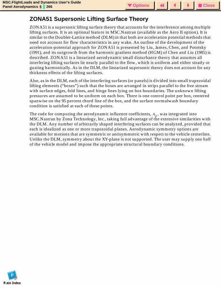
CloseOptionsMSC.FlightLoads and Dynamics User’s GuidePanel Aerodynamics § 266 Options
ZONA51 Supersonic Lifting Surface TheoryZONA51 is a supersonic lifting surface theory that accounts for the interference among multiple lifting surfaces. It is an optional feature in MSC.Nastran (available as the Aero II option). It is similar to the Doublet-Lattice method (DLM) in that both are acceleration potential methods that need not account for flow characteristics in any wake. An outline of the development of the acceleration-potential approach for ZONA51 is presented by Liu, James, Chen, and Pototsky (1991), and its outgrowth from the harmonic gradient method (HGM) of Chen and Liu (1985) is described. ZONA51 is a linearized aerodynamic small disturbance theory that assumes all interfering lifting surfaces lie nearly parallel to the flow, which is uniform and either steady or gusting harmonically. As in the DLM, the linearized supersonic theory does not account for any thickness effects of the lifting surfaces.
Also, as in the DLM, each of the interfering surfaces (or panels) is divided into small trapezoidal lifting elements (“boxes”) such that the boxes are arranged in strips parallel to the free stream with surface edges, fold lines, and hinge lines lying on box boundaries. The unknown lifting pressures are assumed to be uniform on each box. There is one control point per box, centered spanwise on the 95 percent chord line of the box, and the surface normalwash boundary condition is satisfied at each of these points.
The code for computing the aerodynamic influence coefficients, , was integrated into MSC.Nastran by Zona Technology, Inc., taking full advantage of the extensive similarities with the DLM. Any number of arbitrarily shaped interfering surfaces can be analyzed, provided that each is idealized as one or more trapezoidal planes. Aerodynamic symmetry options are available for motions that are symmetric or antisymmetric with respect to the vehicle centerline. Unlike the DLM, symmetry about the XY-plane is not supported. The user may supply one half of the vehicle model and impose the appropriate structural boundary conditions.
Ajj

CloseOptionsMSC.FlightLoads and Dynamics User’s GuidePanel Aerodynamics § 267 Options
Subsonic Wing-Body Interference TheoryThe method of images, along with Slender Body Theory, has been added to the Doublet-Lattice method (DLM) in Giesing, Kalman, and Rodden (1972a, 1972b, and 1972c). The DLM is used to represent the configuration of interfering lifting surfaces, while Slender Body Theory is used to represent the lifting characteristics of each body (i.e., fuselage, nacelle, or external store). The primary wing-body interference is approximated by a system of images of the DLM trailing vortices and doublets within a cylindrical interference body that circumscribes each slender body. The secondary wing-body interference that results from the DLM bound vortices and doublets is accounted for by a line of doublets located on the longitudinal axis of each slender body. The boundary conditions of no flow through the lifting surfaces or through the body (on the average about the periphery) lead to the equations for the lifting pressures on the surfaces and for the longitudinal (and/or lateral) loading on the bodies in terms of the normalwashes on the wing-body combination.
The code for computing the aerodynamic matrices was adapted for MSC.Nastran from Giesing, Kalman, and Rodden (1972b). The adaptation required a matrix formulation of all of the body interference and body loading calculations. These equations are written using the symbols adopted for MSC.Nastran and showing the equivalences to names used in the documentation of Giesing, Kalman, and Rodden (1972b).
The program of Giesing, Kalman, and Rodden (1972b) finds the forces on the lifting boxes and bodies of an idealized airplane in terms of the motions of these elements. The lifting surfaces are divided into boxes. The bodies are divided into elements. There are two types of body elements: slender elements, which are used to simulate a body’s own motion, and interference elements, which are used to simulate the interaction with other bodies and boxes. The body elements may have Z (vertical), Y (lateral), or both (ZY) degrees of freedom.
The basic method is the superposition of singularities and their images. There are two basic singularity types: “forces” and modified acceleration potential “doublets.” Each “force” singularity is equivalent to a line of doublets in the wake. As discussed, the wing boxes use the “force” type of singularity concentrated along the box quarter chord. The interference elements use the “doublet” type of singularity. The slender body elements use both types.
An extensive set of matrix equations dealing with slender body theory as adapted to the Doublet Lattice Method are described in the MSC.Nastran Aeroelastic Guide, and are not reproduced here.
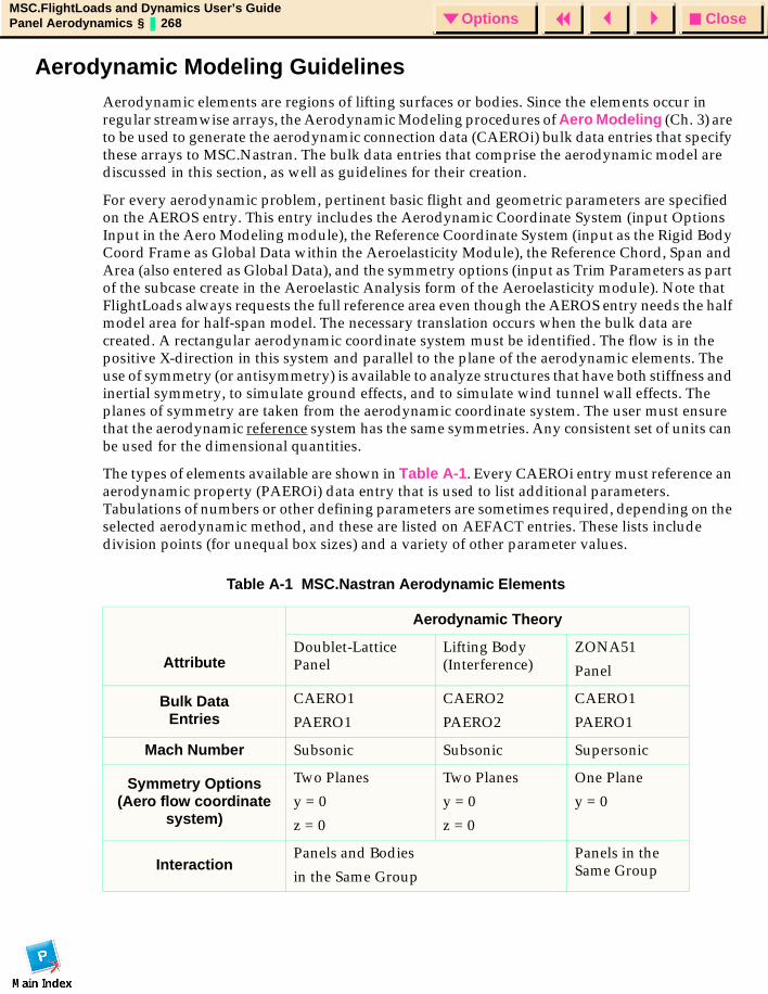
CloseOptionsMSC.FlightLoads and Dynamics User’s GuidePanel Aerodynamics § 268 Options
Aerodynamic Modeling GuidelinesAerodynamic elements are regions of lifting surfaces or bodies. Since the elements occur in regular streamwise arrays, the Aerodynamic Modeling procedures of Aero Modeling (Ch. 3) are to be used to generate the aerodynamic connection data (CAEROi) bulk data entries that specify these arrays to MSC.Nastran. The bulk data entries that comprise the aerodynamic model are discussed in this section, as well as guidelines for their creation.
For every aerodynamic problem, pertinent basic flight and geometric parameters are specified on the AEROS entry. This entry includes the Aerodynamic Coordinate System (input Options Input in the Aero Modeling module), the Reference Coordinate System (input as the Rigid Body Coord Frame as Global Data within the Aeroelasticity Module), the Reference Chord, Span and Area (also entered as Global Data), and the symmetry options (input as Trim Parameters as part of the subcase create in the Aeroelastic Analysis form of the Aeroelasticity module). Note that FlightLoads always requests the full reference area even though the AEROS entry needs the half model area for half-span model. The necessary translation occurs when the bulk data are created. A rectangular aerodynamic coordinate system must be identified. The flow is in the positive X-direction in this system and parallel to the plane of the aerodynamic elements. The use of symmetry (or antisymmetry) is available to analyze structures that have both stiffness and inertial symmetry, to simulate ground effects, and to simulate wind tunnel wall effects. The planes of symmetry are taken from the aerodynamic coordinate system. The user must ensure that the aerodynamic reference system has the same symmetries. Any consistent set of units can be used for the dimensional quantities.
The types of elements available are shown in Table A-1. Every CAEROi entry must reference an aerodynamic property (PAEROi) data entry that is used to list additional parameters. Tabulations of numbers or other defining parameters are sometimes required, depending on the selected aerodynamic method, and these are listed on AEFACT entries. These lists include division points (for unequal box sizes) and a variety of other parameter values.
Table A-1 MSC.Nastran Aerodynamic Elements
Attribute
Aerodynamic Theory
Doublet-Lattice Panel
Lifting Body (Interference)
ZONA51
Panel
Bulk DataEntries
CAERO1
PAERO1
CAERO2
PAERO2
CAERO1
PAERO1
Mach Number Subsonic Subsonic Supersonic
Symmetry Options(Aero flow coordinate
system)
Two Planes
y = 0
z = 0
Two Planes
y = 0
z = 0
One Plane
y = 0
InteractionPanels and Bodies
in the Same Group
Panels in the Same Group
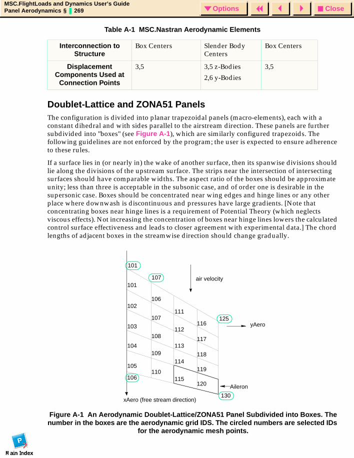
CloseOptionsMSC.FlightLoads and Dynamics User’s GuidePanel Aerodynamics § 269 Options
Doublet-Lattice and ZONA51 PanelsThe configuration is divided into planar trapezoidal panels (macro-elements), each with a constant dihedral and with sides parallel to the airstream direction. These panels are further subdivided into "boxes" (see Figure A-1), which are similarly configured trapezoids. The following guidelines are not enforced by the program; the user is expected to ensure adherence to these rules.
If a surface lies in (or nearly in) the wake of another surface, then its spanwise divisions should lie along the divisions of the upstream surface. The strips near the intersection of intersecting surfaces should have comparable widths. The aspect ratio of the boxes should be approximate unity; less than three is acceptable in the subsonic case, and of order one is desirable in the supersonic case. Boxes should be concentrated near wing edges and hinge lines or any other place where downwash is discontinuous and pressures have large gradients. [Note that concentrating boxes near hinge lines is a requirement of Potential Theory (which neglects viscous effects). Not increasing the concentration of boxes near hinge lines lowers the calculated control surface effectiveness and leads to closer agreement with experimental data.] The chord lengths of adjacent boxes in the streamwise direction should change gradually.
Figure A-1 An Aerodynamic Doublet-Lattice/ZONA51 Panel Subdivided into Boxes. The number in the boxes are the aerodynamic grid IDS. The circled numbers are selected IDs
for the aerodynamic mesh points.
Interconnection to Structure
Box Centers Slender Body Centers
Box Centers
Displacement Components Used at
Connection Points
3,5 3,5 z-Bodies
2,6 y-Bodies
3,5
Table A-1 MSC.Nastran Aerodynamic Elements
air velocity
Aileron
101
102
103
104
105
106
107
108
109
110
111
112
113
114
115
116
117
118
119
120
yAero
xAero (free stream direction)
125
130
107
101
106

CloseOptionsMSC.FlightLoads and Dynamics User’s GuidePanel Aerodynamics § 270 Options
Aerodynamic panels are assigned to interference groups. All panels within a group have aerodynamic interaction. The purpose of the groups is to reduce the computational effort for aerodynamic matrices when it is known that aerodynamic interference is important within the group but otherwise is negligible or to allow the analyst to investigate the effects of aerodynamic interference.
Each panel is described by a CAERO1 Bulk Data entry. A property entry PAERO1 is used to identify associated interference bodies in the subsonic case. A body should be identified as a member of the group if the panel is within one diameter of the surface of the body. The box divisions along the span are determined either by specifying the number of equal boxes NSPAN, or by identifying (by LSPAN), the AEFACT data entry that contains a list of division points in terms of fractions of the span. A similar arrangement is used to specify divisions in the chordwise direction by choosing NCHORD or LCHORD. The locations of the two leading edge points are specified in the coordinate system (CP) defined by the user (including basic). The sides (chords) are in the airstream direction (i.e. parallel to the X-axis of the aerodynamic coordinate system specified on the AEROS Bulk Data entry). Every panel must be assigned to an interference group (IGID). If all panels interact, then IGID must be the same for all panels.
There is an aerodynamic grid point with its associated degrees of freedom in plunge and pitch for each box within a given panel. These points are located at the center of each box and are automatically numbered and sequenced by the program. The lowest aerodynamic grid point number for a given panel is automatically assigned the same number as specified for the panel ID field on the CAERO1 entry starting with the box connected to point 1. The grid point numbers increase in increments of 1 (see the CAERO1 Bulk Data entry description) first in the chordwise direction and then spanwise over all boxes in the panel. There are also corner grid points that are spawned in order to display the aerodynamic mesh. These grid IDs also begin with panel ID at point 1 and are incremented by 1, first in the chordwise and then the spanwise direction over all points on the mesh. (Figure A-1). Note that to insure uniqueness, panel IDs must be separated enough that mesh IDs do not overlap. For example, subsequent panel IDs associated with the panel given in Figure A-1 must be > 130. As a matter of practice, the user should always allow more spacing in numbering so that, during mesh convergence studies, each panel can be independently incremented. The local displacement coordinate system has component T1 in the flow direction and component T3 in the direction normal to the panel in the element coordinate system defined on the CAERO1 entry.
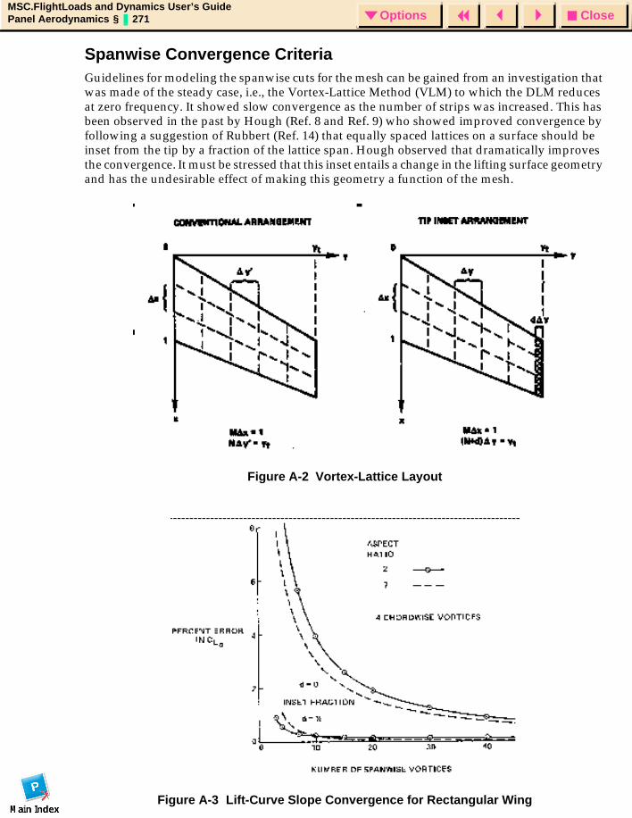
CloseOptionsMSC.FlightLoads and Dynamics User’s GuidePanel Aerodynamics § 271 Options
Spanwise Convergence CriteriaGuidelines for modeling the spanwise cuts for the mesh can be gained from an investigation that was made of the steady case, i.e., the Vortex-Lattice Method (VLM) to which the DLM reduces at zero frequency. It showed slow convergence as the number of strips was increased. This has been observed in the past by Hough (Ref. 8 and Ref. 9) who showed improved convergence by following a suggestion of Rubbert (Ref. 14) that equally spaced lattices on a surface should be inset from the tip by a fraction of the lattice span. Hough observed that dramatically improves the convergence. It must be stressed that this inset entails a change in the lifting surface geometry and has the undesirable effect of making this geometry a function of the mesh.
Figure A-2 Vortex-Lattice Layout
Figure A-3 Lift-Curve Slope Convergence for Rectangular Wing

CloseOptionsMSC.FlightLoads and Dynamics User’s GuidePanel Aerodynamics § 272 Options
With a reasonable number of strips on a surface, say 20 to 30 the error is not large, perhaps 1 to 2% depending on the configuration, and the tip correction may not be worth the effort.
It should be noted that Hough’s argument leading to d=1/4 is based on a symmetrical (elliptical) loading in the steady case and with equal spanwise cuts. Limited calculations indicate that it is also valid in the antisymmetrical (in roll) loading, so the tip correction is recommended in general. Users are advised to perform some convergence checks, with and without the tip correction, they may also wish to investigate placing a refined spanwise mesh at the wing tip without the inset.
If users wish to make the tip correction they can reduce the span of the most outboard panel on each surface on the corresponding CAERO1 continuation entry by the factor NSPAN/(NSPAN + d) where NSPAN is the number of strips on the panel and d is the inset fraction (d = 0.25 is recommended).

CloseOptionsMSC.FlightLoads and Dynamics User’s GuidePanel Aerodynamics § 273 Options
Slender and Interference BodiesIn subsonic problems, bodies are idealized as "slender" and "interference" elements in combination. The primary purpose of the slender body elements is to account for the forces arising from the motion of the body, whereas the interference body elements are used to account for the interference among all bodies and panels in the same group. This is done by providing a surface through which the boundary condition of no flow is imposed. Bodies are further classified as to the type of motion allowed.
In the aerodynamic coordinate system, Y and Z are perpendicular to the flow. In general, bodies may move in both the Y- and Z-directions. Frequently, a body (e.g., a fuselage) lies on a plane of symmetry and only Z- (or Y-) motion is allowed.
Note, however, that MSC.FlightLoads and Dynamics automatically captures the singularities. Thus a ZY-body on the XZ plane of symmetry in symmetric analysis will act as a Z-body without user interaction; in antisymmetric analysis, the same body will act as a Y-body. Thus, any model may contain Z-bodies, ZY-bodies, and Y-bodies.
One or two planes of symmetry or antisymmetry may be specified. Figure A-4 and Figure A-5 shows an idealization with bodies and panels. This example is the one used to illustrate the Doublet-Lattice program in Giesing, Kalman, and Rodden (1972b, pages 19-42). It has a fuselage, a wing, a pylon, and a nacelle.
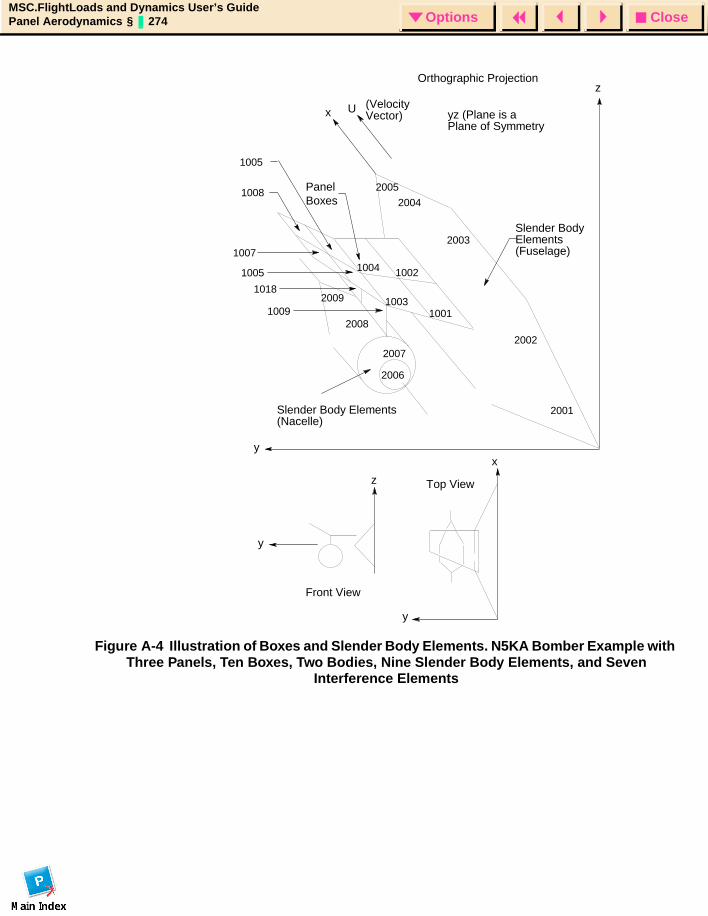
CloseOptionsMSC.FlightLoads and Dynamics User’s GuidePanel Aerodynamics § 274 Options
Figure A-4 Illustration of Boxes and Slender Body Elements. N5KA Bomber Example with Three Panels, Ten Boxes, Two Bodies, Nine Slender Body Elements, and Seven
Interference Elements
Slender BodyElements(Fuselage)
PanelBoxes
1008
1007
Slender Body Elements(Nacelle)
yz (Plane is aPlane of Symmetry
(VelocityVector)
Ux
2001
2002
2003
2004
2005
y
1002
1001
2006
2007
2008
2009
1004
10031009
1018
1005
1005
z
y
x
y
zOrthographic Projection
Front View
Top View
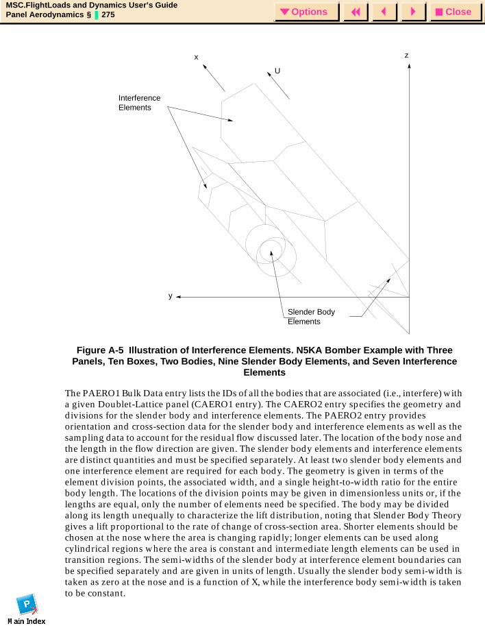
CloseOptionsMSC.FlightLoads and Dynamics User’s GuidePanel Aerodynamics § 275 Options
Figure A-5 Illustration of Interference Elements. N5KA Bomber Example with Three Panels, Ten Boxes, Two Bodies, Nine Slender Body Elements, and Seven Interference
Elements
The PAERO1 Bulk Data entry lists the IDs of all the bodies that are associated (i.e., interfere) with a given Doublet-Lattice panel (CAERO1 entry). The CAERO2 entry specifies the geometry and divisions for the slender body and interference elements. The PAERO2 entry provides orientation and cross-section data for the slender body and interference elements as well as the sampling data to account for the residual flow discussed later. The location of the body nose and the length in the flow direction are given. The slender body elements and interference elements are distinct quantities and must be specified separately. At least two slender body elements and one interference element are required for each body. The geometry is given in terms of the element division points, the associated width, and a single height-to-width ratio for the entire body length. The locations of the division points may be given in dimensionless units or, if the lengths are equal, only the number of elements need be specified. The body may be divided along its length unequally to characterize the lift distribution, noting that Slender Body Theory gives a lift proportional to the rate of change of cross-section area. Shorter elements should be chosen at the nose where the area is changing rapidly; longer elements can be used along cylindrical regions where the area is constant and intermediate length elements can be used in transition regions. The semi-widths of the slender body at interference element boundaries can be specified separately and are given in units of length. Usually the slender body semi-width is taken as zero at the nose and is a function of X, while the interference body semi-width is taken to be constant.
Slender BodyElements
InterferenceElements
y
z
U
x
CloseOptionsMSC.FlightLoads and Dynamics User’s GuidePanel Aerodynamics § 276 Options
The interference elements are intended for use only with panels and/or other bodies, while slender body elements can stand alone. Grid points are generated only for the slender body elements. The first grid point is assigned the ID of the body corresponding to the element at the nose and other grid points are incremented by one. The user should be cautious about the use of associated interference bodies since they increase computational effort significantly.
A brief review of the Method of Images (and its approximations) follows before the implementation of the method in MSC.Nastran is discussed.
The interference elements provide the basis for the internal image system that cancels most of the effects of the trailing vortices from the lifting surfaces. Because of the two-dimensional basis for this approximation (Thompson's Circle Theorem in Hydrodynamics), the body surface has been approximated by a constant elliptical cross-section cylinder called the interference tube. All panels that intersect a body must be attached to the interference tube. Image locations are computed from the semi-width of the interference tube for all lifting surfaces associated with the body. The image is only computed if it lies between the front and aft of the interference element for the associated body.
There is a residual flow "through" the body surface because the image system, being based on two-dimensional considerations, only partially cancels the flow through the body surface. It does not compensate for the effects of the bound vortices on the lifting surfaces or other bodies. Additional unknown "residual" doublets are located along the axis of the body, and, when determined, are added to the known doublet strengths of the slender body elements. The residual flow is calculated by "sampling" the vertical or side velocity components from the net effect of the surface, slender body, and image vortices or doublets. The sampling is performed at various angular positions around the periphery of the elliptical interference tube at the end points of the interference elements. The strengths of the "residual" doublets are then determined to cancel the net velocity.
The calculation of the velocity field induced by the residual doublets requires knowledge of the geometry of the cross section of the slender body at the end points of the interference elements. However, experience shows that the residual flow is small compared to the slender body flow field so that the residual flow need not be represented accurately. This permits the further approximation of simply using the geometry of the constant cross-section interference tube in the calculation of the velocities induced by the residual doublets.
A discussion of two related problems follows:
The requirement for a constant cross-section interference tube may require moving the stabilizer (or wing); see Giesing, Kalman, and Rodden (1972a, §2.5.8). MSC.Nastran can accommodate the requirements by specifying a stabilizer coordinate system, two sets of GRID points for the (same) stabilizer root and its fuselage connection, and MPCs constraining the motions of the two sets of GRIDs to be the same. In this way, the structure can be modeled faithfully although the aerodynamic model is only approximate. This is illustrated in the example "FSW Airplane with Bodies" (HA144F) in Chapter 7 of the MSC.Nastran Aeroelastic User’s Guide.
The idealization of a jet engine installation as a slender body results in a mass flow ratio through the engine of zero, since there is no flow through the body. Idealizing the engine as a ring-wing results in a mass flow ratio of unity, since all the flow goes through the tube. A typical mass flow ratio is 0.7, so a ring-wing representation is more appropriate.
CloseOptionsMSC.FlightLoads and Dynamics User’s GuideSplines § 277 Options
MSC/.FlightLoads and Dynamics User’s Guide
APPENDIX
B Splines
Introduction
Theoretical Development
Guidelines
Spline Metrics
CloseOptionsMSC.FlightLoads and Dynamics User’s GuideSplines § 278 Options
IntroductionIn the context of MSC.FlightLoads and Dynamics, Splines provide an interpolation capability that couples the disjoint structural and aerodynamic models in order to enable the static aeroelastic analysis. The aeroelastic splines are used for two distinct purposes: as a force interpolator to compute a structurally equivalent force distribution on the structure given a force distribution on the aerodynamic mesh and as a displacement interpolator to compute a set of aerodynamic displacements given a set of structural displacements. The force interpolation is represented mathematically as:
Eq. 2-1
and the displacement interpolation as:
Eq. 2-2
Where G is the spline matrix, F and U refer to forces and displacements, respectively and the s and a subscripts refer to structure and aerodynamics, respectively.
The two splines given in the above relationships are used when making the force and displacement interpolations. However, virtual work principals can be applied to relate the two splines as being the transform of one another:
Eq. 2-3
That is, the same set of aerodynamic and structural degrees of freedom are coupled for both interpolation functions. While this relationship is valid, this usage assumption is not necessary and can be limiting for static aeroelastic applications where the set of structural DOFs that is appropriate for load application may not be the same set that is appropriate to represent the important deflections for the aeroelastic correction. Therefore, as shown with the Type option of Aero-Structure Coupling (Ch. 5), each spline can be either General (same spline used for Force and Displacement), Displacement or Force.
Splining methods for aeroelastic analyses available in FlightLoads include the Harder-Desmarais Infinite Plate Spline (SPLINE1 or SPLINE4 with METH=IPS), the Infinite Beam Spline (SPLINE2),the Thin Plate Spline (SPLINE1 or SPLINE4 with METH=TPS) and the Finite Plate Spline (SPLINE1 or SPLINE4 with METH=FPS). A fifth method that employs an MPC-like interpolator (SPLINE3) is available in MSC.Nastran, but is not supported in FlightLoads. The SPLINE3 allows the user to build an interconnection between select aerodynamic DOFs and select structural DOFs and is not discussed further here.
The IPS, FPS and the linear spline assume that the aerodynamic and structural points for a single interpolation matrix lie on or can be projected to the same plane. They relate structural displacements normal to that plane to aerodynamic displacements normal to the plane and to an aerodynamic slope (rotation about a single axis lying in the plane). The TPS is a three dimensional extension of the existing IPS spline. The FPS uses a virtual planar finite element mesh to interpolate between the two meshes.
As stated in Eq. 2-1 and Eq. 2-2, the two basic relationships that must be developed are the displacement transformation and the force transformation. In general, the structural displacements are the usual six global displacement degrees of freedom and the forces are the usual three forces and three moments. The aerodynamic degrees of freedom depend on the
Fs Gsa Fa=
Ua Gas Us=
Gsa Gas
T=
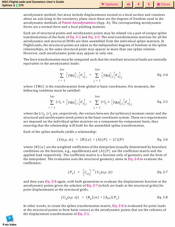
CloseOptionsMSC.FlightLoads and Dynamics User’s GuideSplines § 279 Options
aerodynamic method, but must include displacements normal to a local surface and rotations about an axis lying in the osculatory plane since these are the degrees of freedom used in the aerodynamic methods of Panel Aerodynamics (App. A). The corresponding aerodynamic forces are a normal force and a local pitching moment.
Each set of structural points and aerodynamic points may be related via a pair of unique spline transformations of the form of Eq. 2-1 and Eq. 2-2. The total transformation matrices for all the aerodynamic and structural DOFs are then assembled from the individual spline matrices. In FlightLoads, the structural points are taken as the independent degrees of freedom in the spline relationships, so the same structural point may appear in more than one spline relation. However, each aerodynamic point may appear in only one.
The force transformation must be computed such that the resultant structural loads are statically equivalent to the aerodynamic loads:
Eq. 2-4
where is the transformation from global to basic coordinates. For moments, the following condition must be satisfied:
Eq. 2-5
where the are, respectively, the vectors between the (arbitrary) moment center and the structural and aerodynamic mesh points in the basic coordinate system. These two requirements are imposed on the individual spline matrices on a component-by-component basis, thus ensuring that the relationship will hold for the assembled spline transformation.
Each of the spline methods yields a relationship:
Eq. 2-6
where are the weighted coefficients of the interpolant (usually determined by boundary conditions on the function, e.g., equilibrium) and are the coefficient matrix and the applied load respectively. The coefficient matrix is a function only of geometry and the form of the interpolant. The evaluation uses the structural geometry alone in Eq. 2-6 to evaluate the coefficients:
Eq. 2-7
and then uses Eq. 2-6 again, with both geometries to evaluate the displacement function at the aerodynamic points given the solution of Eq. 2-7 (which are loads at the structural grids) for point displacements at the structural grids.
Eq. 2-8
In other words, to create the spline transformation matrix, Eq. 2-6 is evaluated for point loads at the structural points to form basis vectors at the aerodynamic points that are the columns of the displacement transformation of Eq. 2-1.
TBG i Fs ii 1=
3ns
∑ TBA j Fa jj 1=
3na
∑=
TBG[ ]
r[ ]i TBG×i Fs i
i 1=
3ns
∑ r[ ]j TBA×j Fa j
j 1=
3na
∑=
r[ ] i r[ ]j,
U x y z,( , ) R[ ] a A[ ] P C[ ] P[ ]=+=
R[ ] a A[ ] P
Ps Css1–
Us x y z,( , ) =
Ua x y z,( , ) Ra[ ] a Aas[ ] Ps +=
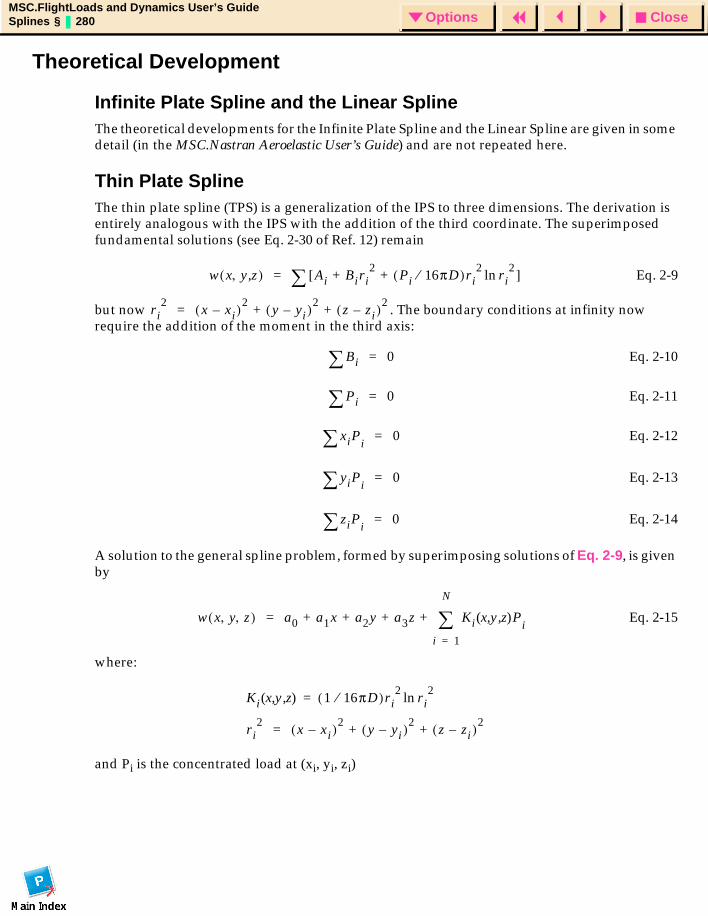
CloseOptionsMSC.FlightLoads and Dynamics User’s GuideSplines § 280 Options
Theoretical Development
Infinite Plate Spline and the Linear Spline The theoretical developments for the Infinite Plate Spline and the Linear Spline are given in some detail (in the MSC.Nastran Aeroelastic User’s Guide) and are not repeated here.
Thin Plate SplineThe thin plate spline (TPS) is a generalization of the IPS to three dimensions. The derivation is entirely analogous with the IPS with the addition of the third coordinate. The superimposed fundamental solutions (see Eq. 2-30 of Ref. 12) remain
Eq. 2-9
but now . The boundary conditions at infinity now require the addition of the moment in the third axis:
Eq. 2-10
Eq. 2-11
Eq. 2-12
Eq. 2-13
Eq. 2-14
A solution to the general spline problem, formed by superimposing solutions of Eq. 2-9, is given by
Eq. 2-15
where:
and Pi is the concentrated load at (xi, yi, zi)
w x y z,,( ) Ai Biri2
Pi 16πD⁄( )ri2
ri2ln+ +[ ]∑=
ri2
x xi–( )2y yi–( )2
z zi–( )2+ +=
Bi∑ 0=
Pi∑ 0=
xiPi∑ 0=
yiPi∑ 0=
ziPi∑ 0=
w x y z, ,( ) a0 a1x a2y a3z+ + + Ki x y z,( , )Pi
i 1=
N
∑+=
Ki x y z,( , ) 1 16πD⁄( )ri2
ri2ln=
ri2
x xi–( )2y yi–( )2
z zi–( )2+ +=
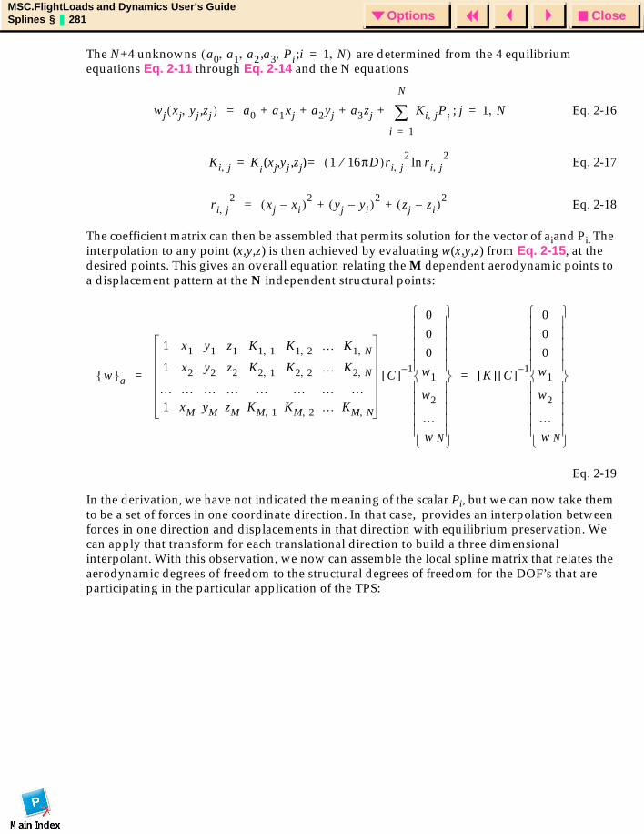
CloseOptionsMSC.FlightLoads and Dynamics User’s GuideSplines § 281 Options
The N+4 unknowns are determined from the 4 equilibrium equations Eq. 2-11 through Eq. 2-14 and the N equations
Eq. 2-16
Eq. 2-17
Eq. 2-18
The coefficient matrix can then be assembled that permits solution for the vector of aiand Pi. The interpolation to any point (x,y,z) is then achieved by evaluating w(x,y,z) from Eq. 2-15, at the desired points. This gives an overall equation relating the M dependent aerodynamic points to a displacement pattern at the N independent structural points:
Eq. 2-19
In the derivation, we have not indicated the meaning of the scalar Pi, but we can now take them to be a set of forces in one coordinate direction. In that case, provides an interpolation between forces in one direction and displacements in that direction with equilibrium preservation. We can apply that transform for each translational direction to build a three dimensional interpolant. With this observation, we now can assemble the local spline matrix that relates the aerodynamic degrees of freedom to the structural degrees of freedom for the DOF’s that are participating in the particular application of the TPS:
a0 a1 a2 a3, Pi i 1 N,=;, , ,( )
wj xj yj zj,,( ) a0 a1xj a2yj a3zj+ + + Ki j, Pi
j 1 N,=;
i 1=
N
∑+=
Ki j, K=i
xj yj zj,( , ) 1 16πD⁄( )= ri j,2
ri j,2ln
ri j,2
xj xi–( )2yj yi–( )2
zj zi–( )2+ +=
w a
1 x1 y1 z1 K1 1, K1 2, … K1 N,
1 x2 y2 z2 K2 1, K2 2, … K2 N,
… … … … … … … …1 xM yM zM KM 1, KM 2, … KM N,
C[ ] 1–
000
w1
w2
…w N
K[ ] C[ ] 1–
000
w1
w2
…w N
= =
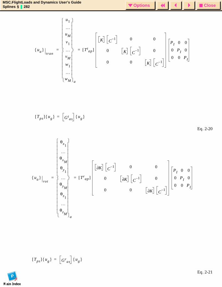
CloseOptionsMSC.FlightLoads and Dynamics User’s GuideSplines § 282 Options
Eq. 2-20
Eq. 2-21
ua tran
u1
…uM
v1
…vM
w1
…wM
a
Ttap[ ]
K C1– 0 0
0 K C1– 0
0 0 K C1–
=
PI 0 0
0 PI 0
0 0 PI
Tps[ ] ug Gtas
ug =
=
ua rot
θx1
…θxM
θy1
…θyM
θz1
…θzM
a
Trap[ ]
K∂ C1– 0 0
0 K∂ C1– 0
0 0 K∂ C1–
=
PI 0 0
0 PI 0
0 0 PI
Tps[ ] ug Gras
ug =
=
CloseOptionsMSC.FlightLoads and Dynamics User’s GuideSplines § 283 Options
where:
Eq. 2-22
and are the three assembled 3x3 transformation matrices that relate the aerodynamic coordinate system to the spline coordinate system. Similarly, is the assembled 3x3 transformation matrices that relate the structural displacements to the spline component directions. Just as in the 2-D case, the structural rotations are not involved in this spline formulation.
Most of the difference between this 3-D version and its 2-D counterpart is in the formation of the matrices to account for separate treatment of each displacement
component instead of a single planar interpolation surface.
Singularity Conditions: In the 2-D case, the spline interpolant is singular if the independent (structural) points are all collinear. In the 3-D case, the interpolant is singular if the independent points are all coplanar. If the TPS interpolant is found to be singular, the code automatically reverts to a 2-D interpolant with the spline plane defined by the plane of the coplanar structural grid points. In the case of a singular 2-D case, a fatal error is issued, since we do not attempt to revert to a beam spline.
PI
0 0 … 00 0 … 00 0 … 01 0 … 00 1 … 0
… … … …0 0 … 1 3 N+ N×
=
Ttap[ ] Tr
ap[ ],Tps[ ]
Ttap[ ] Tr
ap[ ] Tps[ ],,
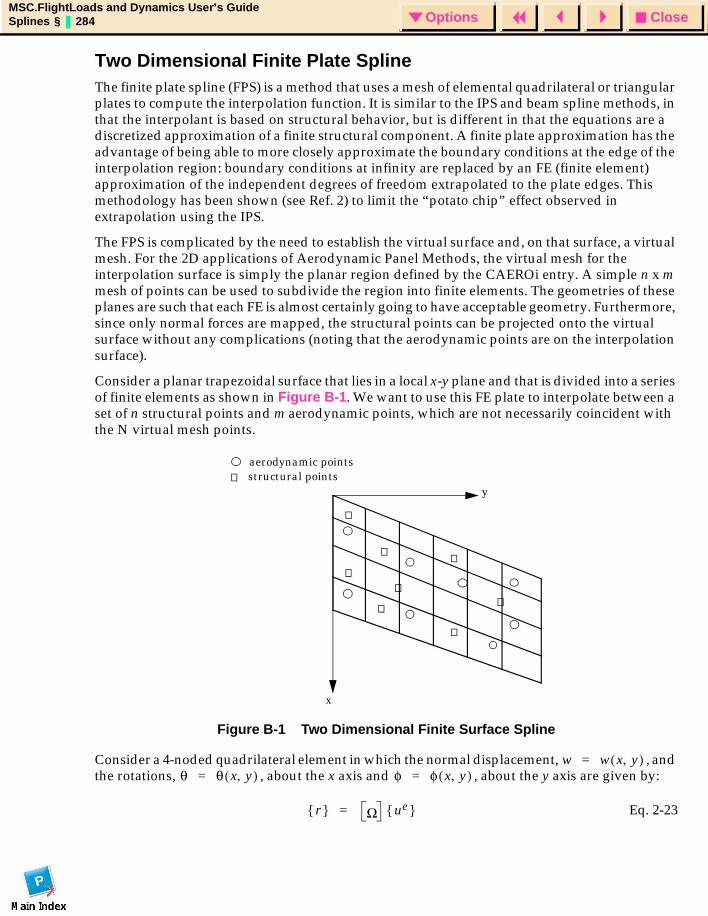
CloseOptionsMSC.FlightLoads and Dynamics User’s GuideSplines § 284 Options
Two Dimensional Finite Plate SplineThe finite plate spline (FPS) is a method that uses a mesh of elemental quadrilateral or triangular plates to compute the interpolation function. It is similar to the IPS and beam spline methods, in that the interpolant is based on structural behavior, but is different in that the equations are a discretized approximation of a finite structural component. A finite plate approximation has the advantage of being able to more closely approximate the boundary conditions at the edge of the interpolation region: boundary conditions at infinity are replaced by an FE (finite element) approximation of the independent degrees of freedom extrapolated to the plate edges. This methodology has been shown (see Ref. 2) to limit the “potato chip” effect observed in extrapolation using the IPS.
The FPS is complicated by the need to establish the virtual surface and, on that surface, a virtual mesh. For the 2D applications of Aerodynamic Panel Methods, the virtual mesh for the interpolation surface is simply the planar region defined by the CAEROi entry. A simple n x m mesh of points can be used to subdivide the region into finite elements. The geometries of these planes are such that each FE is almost certainly going to have acceptable geometry. Furthermore, since only normal forces are mapped, the structural points can be projected onto the virtual surface without any complications (noting that the aerodynamic points are on the interpolation surface).
Consider a planar trapezoidal surface that lies in a local x-y plane and that is divided into a series of finite elements as shown in Figure B-1. We want to use this FE plate to interpolate between a set of n structural points and m aerodynamic points, which are not necessarily coincident with the N virtual mesh points.
Figure B-1 Two Dimensional Finite Surface Spline
Consider a 4-noded quadrilateral element in which the normal displacement, , and the rotations, , about the x axis and , about the y axis are given by:
Eq. 2-23
y
x
aerodynamic pointsstructural points
w w x y,( )=θ θ x y,( )= φ φ x y,( )=
r Ω ue =
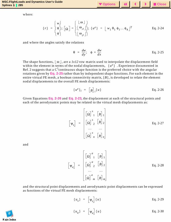
CloseOptionsMSC.FlightLoads and Dynamics User’s GuideSplines § 285 Options
where:
Eq. 2-24
and where the angles satisfy the relations
Eq. 2-25
The shape functions, , are a 1x12 row matrix used to interpolate the displacement field within the element in terms of the nodal displacements, . Experience documented in Ref. 2 suggests that a C1continuous shape function is the preferred choice with the angular rotations given by Eq. 2-25 rather than by independent shape functions. For each element in the entire virtual FE mesh, a boolean connectivity matrix, , is developed to relate the element nodal displacements to the overall FE mesh displacements:
Eq. 2-26
Given Equations Eq. 2-26 and Eq. 2-23, the displacement at each of the structural points and each of the aerodynamic points may be related to the virtual mesh displacements as:
Eq. 2-27
and
Eq. 2-28
and the structural point displacements and aerodynamic point displacements can be expressed as functions of the virtual FE mesh displacements:
Eq. 2-29
Eq. 2-30
r w
θφ
Ω
ωω x,
ω y,
ue ;=; w1 θ1 φ1… φ4T= =
θyd
dw φxd
dw=;=
ωue
B[ ]
ue i B iu =
ψs
Ωs
1
Ωs
2
B 1
B 2
… …
Ωs
n B n
=
ψa
Ωa
1
Ωa
2
B 1
B 2
… …
Ωa
m B m
=
us ψs u =
ua ψa u =
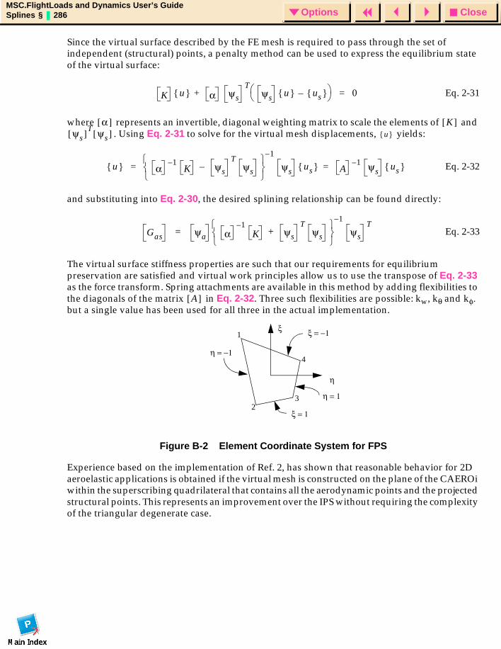
CloseOptionsMSC.FlightLoads and Dynamics User’s GuideSplines § 286 Options
Since the virtual surface described by the FE mesh is required to pass through the set of independent (structural) points, a penalty method can be used to express the equilibrium state of the virtual surface:
Eq. 2-31
where represents an invertible, diagonal weighting matrix to scale the elements of and . Using Eq. 2-31 to solve for the virtual mesh displacements, yields:
Eq. 2-32
and substituting into Eq. 2-30, the desired splining relationship can be found directly:
Eq. 2-33
The virtual surface stiffness properties are such that our requirements for equilibrium preservation are satisfied and virtual work principles allow us to use the transpose of Eq. 2-33 as the force transform. Spring attachments are available in this method by adding flexibilities to the diagonals of the matrix in Eq. 2-32. Three such flexibilities are possible: kw, kθ and kφ. but a single value has been used for all three in the actual implementation.
Figure B-2 Element Coordinate System for FPS
Experience based on the implementation of Ref. 2, has shown that reasonable behavior for 2D aeroelastic applications is obtained if the virtual mesh is constructed on the plane of the CAEROi within the superscribing quadrilateral that contains all the aerodynamic points and the projected structural points. This represents an improvement over the IPS without requiring the complexity of the triangular degenerate case.
K u α ψs
Tψs u us –
+ 0=
α[ ] K[ ]ψs[ ]T ψs[ ] u
u α1–
K ψs–T
ψs
1–
ψs us A1– ψs us ==
Gas ψa α1–
K ψs
Tψs+
1–
ψs
T=
A[ ]
ξ
η
ξ = −1
ξ = 1
η = −1
η = 1
1
23
4
CloseOptionsMSC.FlightLoads and Dynamics User’s GuideSplines § 287 Options
Spring Attachments and Interpolation SmoothingEach of the splining methods lends itself to a smoothing parameter or parameters that can loosen the requirement that the interpolation “surface” pass through the structural points. This feature is useful in that, for certain selections of interpolating structural grid points, forcing the spline function to pass through all of the points causes oscillation in the interpolant (e.g., when a number of closely space grid points are attached to the spline function) or when the set of structural grid points overspecifies the behavior of the spline and causes a singularity (e.g., when more than two grids are attached to the same axial station of a beam spline or when both translations and rotations are applied at the same axial station of a beam spline).
Relaxing the equality criterion at a point can be thought of as a translational and/or torsional spring that attaches the structural point to the interpolation surface. Mathematically, this is presented in Ref. 2 and repeated here for completeness.
Each of the interpolation functions can be represented as:
Eq. 2-34
where represents the spline surface deflection under a set of point loads. If the structural points are connected to the spline surface by springs, the structural displacements will differ from the spline surface deformation by the deformation of the spring. The spring deformation results in forces:
Eq. 2-35
where the diagonal matrix of spring stiffnesses, . These stiffnesses are nonzero (since, if they were zero, the structural grid point would be disconnected from the spline surface and would be omitted from the set), so an inverse exists. This results in a modification to the influence coefficient matrix in Eq. 2-34:
Eq. 2-36
Thus, all that is required with any of these interpolation methods to introduce smoothing is to add a “spring flexibility” to the diagonals of the influence coefficient matrix.
U x y z,( , ) R[ ] a A[ ] P C[ ] P[ ]=+=
U x y z,( , )
P x y z,( , ) Ks[ ] Ug Ua –( )=
Ks[ ]
U x y z,( , ) R[ ] a A[ ] Ks[ ] 1–+( ) P +=
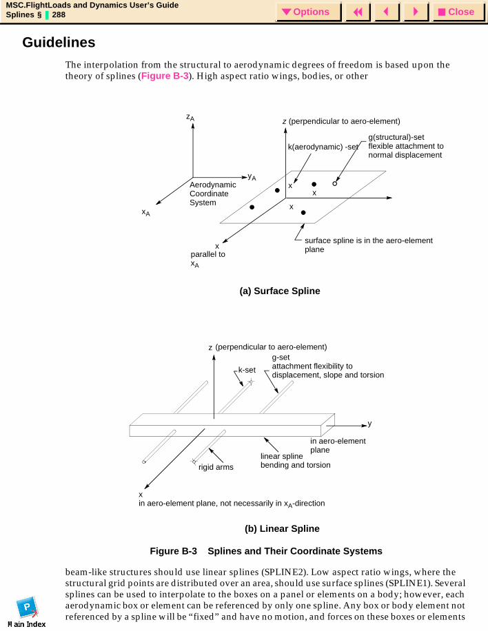
CloseOptionsMSC.FlightLoads and Dynamics User’s GuideSplines § 288 Options
Guidelines The interpolation from the structural to aerodynamic degrees of freedom is based upon the theory of splines (Figure B-3). High aspect ratio wings, bodies, or other
Figure B-3 Splines and Their Coordinate Systems
beam-like structures should use linear splines (SPLINE2). Low aspect ratio wings, where the structural grid points are distributed over an area, should use surface splines (SPLINE1). Several splines can be used to interpolate to the boxes on a panel or elements on a body; however, each aerodynamic box or element can be referenced by only one spline. Any box or body element not referenced by a spline will be “fixed” and have no motion, and forces on these boxes or elements
xx
x
Aerodynamic Coordinate System
z (perpendicular to aero-element)
k(aerodynamic) -setg(structural)-set flexible attachment to normal displacement
surface spline is in the aero-element plane
parallel to xA
x
xA
zA
yA
(a) Surface Spline
(b) Linear Spline
z
k-set
g-setattachment flexibility todisplacement, slope and torsion
rigid armslinear splinebending and torsion
y
x in aero-element plane, not necessarily in xA-direction
in aero-element plane
(perpendicular to aero-element)
CloseOptionsMSC.FlightLoads and Dynamics User’s GuideSplines § 289 Options
will not be applied to the structure. A linear relationship (like an MPC) may be specified for any aerodynamic point using the SPLINE3 entry. This is particularly useful for control surface rotations.
For all types of splines, the user must specify the structural degrees of freedom and the aerodynamic points involved. The degrees of freedom utilized at the grid points include only the normal displacements for surface splines. For linear splines, the normal displacement is always used and, by user option, torsional rotations and/or slopes may be included.
The SPLINE1 data entry defines a surface spline This can interpolate for any “rectangular” subarray of boxes on a panel. For example, one spline can be used for the inboard end of a panel and another for the outboard end. The interpolated aerodynamic degrees of freedom (k-set) are specified by naming the lowest and highest aerodynamic grid point numbers in the area to be splined. A parameter DZ is used to allow smoothing of the spline fit. If (the recommended value), the spline will pass through all deflected grid points. If , then the spline (a plate) is attached to the deflected grid points via springs, which produce a smoother interpolation that does not necessarily pass through any of the points. The flexibility of the springs is proportional to DZ.
Three different methods of surface splines can be invoked with the METH field on the SPLINE1 entry: IPS, TPS and FPS (infinite, thin and finite plate spline, respectively). For the flat plate aerodynamics contained in FLDS, there is little benefit from selecting the TPS. If the TPS is selected and all the grids are coplanar, the algorithm automatically reverts to IPS in any case. The FPS is a recent addition to the arsenal of spline methods in MSC.Nastran and is believed to provide improved performance relative to the two infinite splines since it is better able to handle the deformation patterns at the edge of the aerodynamic panel. It is therefore recommended that the FPS be selected, but that the other two methods are available as a fallback if FPS performance is not satisfactory.
The USAGE flag on the SPLINE1 entry identifies whether the spline is to be used to transform forces, displacements or both (FORCE, DISP or BOTH). The BOTH option is often acceptable, but the other options provide the ability to tailor the splining to the application. Since the force transformation imposes loads on the structure, it is reasonable to select grid points that can withstand this loading without severe deformations. The displacement transformation requires an accurate representation of the overall deformation pattern, so it is quite conceivable that a different set of grids from the force transform would be the most appropriate.
DZ 0=
DZ 0>
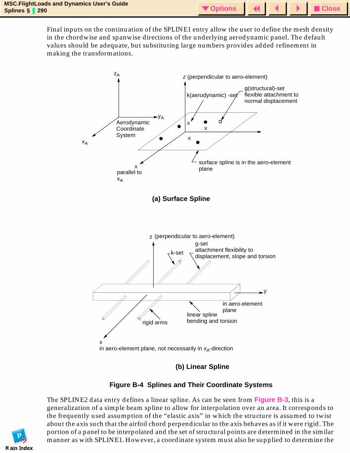
CloseOptionsMSC.FlightLoads and Dynamics User’s GuideSplines § 290 Options
Final inputs on the continuation of the SPLINE1 entry allow the user to define the mesh density in the chordwise and spanwise directions of the underlying aerodynamic panel. The default values should be adequate, but substituting large numbers provides added refinement in making the transformations.
Figure B-4 Splines and Their Coordinate Systems
The SPLINE2 data entry defines a linear spline. As can be seen from Figure B-3, this is a generalization of a simple beam spline to allow for interpolation over an area. It corresponds to the frequently used assumption of the “elastic axis” in which the structure is assumed to twist about the axis such that the airfoil chord perpendicular to the axis behaves as if it were rigid. The portion of a panel to be interpolated and the set of structural points are determined in the similar manner as with SPLINE1. However, a coordinate system must also be supplied to determine the
xx
x
Aerodynamic Coordinate System
z (perpendicular to aero-element)
k(aerodynamic) -setg(structural)-set flexible attachment to normal displacement
surface spline is in the aero-element plane
parallel to xA
x
xA
zA
yA
(a) Surface Spline
(b) Linear Spline
z
k-set
g-setattachment flexibility todisplacement, slope and torsion
rigid armslinear splinebending and torsion
y
x in aero-element plane, not necessarily in xA-direction
in aero-element plane
(perpendicular to aero-element)
CloseOptionsMSC.FlightLoads and Dynamics User’s GuideSplines § 291 Options
axis of the spline (which is the elastic axis of the virtual beam); a coordinate system with its Y-axis collinear with the spline axis is required. That coordinate system should be somewhere near the true elastic axis and approximately aligned with it (e.g., swept if the elastic axis is swept). Since the spline has torsion and bending flexibility, the user may specify the ratio DTOR of flexibilities for a wing as a representative value of ; the default value for this ratio is 1.0. The attachment flexibilities, , , and allow for smoothing, but usually all values are taken to be zero; when the attachment flexibilities are taken to be zero, the spline passes through all of the connected grid points and the value of the ratio DTOR has no effect. In the case where the structural model does not have one or both slopes defined, the convention
and/or is used. When used with bodies, there is no torsion and the spline axis is along the body so that a user input coordinate system is not required.
There are special cases with splines where attachment flexibility is either required or should not be used. The following special cases should be noted:
1. Two or more grid points, when projected onto the plane of the element (or the axis of a body), may have the same location. To avoid a singular interpolation matrix, a positive attachment flexibility must be used (or better yet, only one grid point selected at that location).
2. With linear splines, three deflections with the same spline Y-coordinate over determine the interpolated deflections since the perpendicular arms are rigid. A positive DZ is needed to make the interpolation matrix nonsingular.
3. With linear splines, two slopes (or twists) at the same Y-coordinate lead to a singular interpolation matrix. Use (or ) to allow interpolation.
4. For some modeling techniques, i.e., those which use only displacement degrees of freedom, the rotations of the structural model are constrained to zero to avoid matrix singularities. If a linear spline is used, the rotational constraints should not be enforced to these zero values. When used for panels, negative values of DTHX will disconnect the slope, and negative values of DTHY will disconnect the twist. For bodies, DTHY constrains the slopes since there is no twist degree of freedom for body interpolation.
The USAGE flag on the SPLINE2 entry performs the same function as on the SPLINE1.
The SPLINE4 bulk data entry is very similar to the SPLINE1 entry. The difference is that the SPLINE4 entry invokes a list of aerodynamic elements that are to be included in the spline while the SPLINE1 entry selects the first and last aerodynamic box to be splined and allows the spline algorithm to determine the intermediate box ID’s.
The SPLINE5 bulk data entry is very similar to the SPLINE2 entry. The difference is the use of a list of aerodynamic elements rather than using "first box - last box" logic.
EI( ) GJ( )⁄Dx dθx Dθy
DTHX 1.0–= DTHY 1.0–=
DTHX 0> DTHY 0>
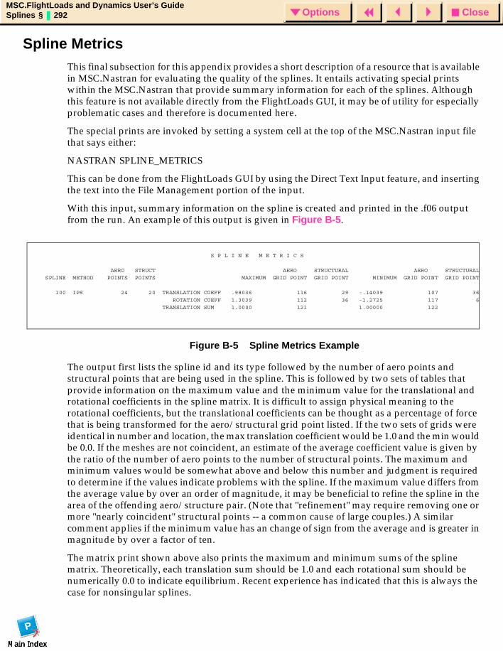
CloseOptionsMSC.FlightLoads and Dynamics User’s GuideSplines § 292 Options
Spline Metrics This final subsection for this appendix provides a short description of a resource that is available in MSC.Nastran for evaluating the quality of the splines. It entails activating special prints within the MSC.Nastran that provide summary information for each of the splines. Although this feature is not available directly from the FlightLoads GUI, it may be of utility for especially problematic cases and therefore is documented here.
The special prints are invoked by setting a system cell at the top of the MSC.Nastran input file that says either:
NASTRAN SPLINE_METRICS
This can be done from the FlightLoads GUI by using the Direct Text Input feature, and inserting the text into the File Management portion of the input.
With this input, summary information on the spline is created and printed in the .f06 output from the run. An example of this output is given in Figure B-5.
Figure B-5 Spline Metrics Example
The output first lists the spline id and its type followed by the number of aero points and structural points that are being used in the spline. This is followed by two sets of tables that provide information on the maximum value and the minimum value for the translational and rotational coefficients in the spline matrix. It is difficult to assign physical meaning to the rotational coefficients, but the translational coefficients can be thought as a percentage of force that is being transformed for the aero/structural grid point listed. If the two sets of grids were identical in number and location, the max translation coefficient would be 1.0 and the min would be 0.0. If the meshes are not coincident, an estimate of the average coefficient value is given by the ratio of the number of aero points to the number of structural points. The maximum and minimum values would be somewhat above and below this number and judgment is required to determine if the values indicate problems with the spline. If the maximum value differs from the average value by over an order of magnitude, it may be beneficial to refine the spline in the area of the offending aero/structure pair. (Note that "refinement" may require removing one or more "nearly coincident" structural points -- a common cause of large couples.) A similar comment applies if the minimum value has an change of sign from the average and is greater in magnitude by over a factor of ten.
The matrix print shown above also prints the maximum and minimum sums of the spline matrix. Theoretically, each translation sum should be 1.0 and each rotational sum should be numerically 0.0 to indicate equilibrium. Recent experience has indicated that this is always the case for nonsingular splines.
S P L I N E M E T R I C S
AERO STRUCT AERO STRUCTURAL AERO STRUCTURAL SPLINE METHOD POINTS POINTS MAXIMUM GRID POINT GRID POINT MINIMUM GRID POINT GRID POINT
100 IPS 24 20 TRANSLATION COEFF .98036 116 29 -.14039 107 36
ROTATION COEFF 1.3039 112 36 -1.2725 117 6 TRANSLATION SUM 1.0000 121 1.00000 122
CloseOptionsMSC.FlightLoads and Dynamics User’s GuideResults Interface via XDB § 293 Options
MSC.FlightLoads and Dynamics User’s Guide
APPENDIX
C Results Interface via XDB
XDB Output
CloseOptionsMSC.FlightLoads and Dynamics User’s GuideResults Interface via XDB §3.1 294 Options
3.1 XDB OutputIf PARAM,POST,0 is requested in SOL 144, a large number of new outputs become available. First, the aerodynamic mesh (for Doublet Lattice Slender Body geometries) is stored so that the unit solutions and trim solutions can be visualized in MSC.Patran using either the NASTRAN preference or FlightLoads. Without MSC.FLD, you must import both the model and the results. Using MSC.FLD, you will typically have the model already available in MSC.Patran. When the XDB is attached to PATRAN for both model and results data, the aerodynamic model will be imported and placed in a GROUP named “Aero Model CONFIG=<aeconfig>” where <aeconfig> is the AECONFIG name assigned in Case Control. The structural model is imported as before, except it will be placed in the group entitled “Aeroelastic Structural Model.”
In the Results module of MSC.Patran, the trim subcase data and unit solution data are available to be visualized on both the structural mesh and the aerodynamic mesh. These data consist of both displacements and several force components. The data are divided into TRIM results (subcases labelled SC<subcase index>) and “Flexible Increments (labelled FI <condition and parameter identifier>)” that represent the unit solution results. Each of these “Result Cases” (in the PATRAN parlance) is further divided into several “Results Types” that are the rigid, elastic, inertial, and total loads and the displacements. For Flexible Increments, both restrained and unrestrained data are available. For TRIM subcases, only restrained data are used to create the linear combination that is the TRIM result.
The Result Case labels are formed using the following rules:
• SC<subcase index><config>
• <subcase index> is the subcase index, e.g., SC1 or SC2
• <config> is the AECONFIG name if the result case applies to the aerodynamic mesh and is the word “Structure” if it applies to the structural model.
• FI: <config> M=<mach>, Sxy=<sym>, DC=<controller>, Q=<q>, Sxz=<sym>
• <config> is the AECONFIG name from Case Control if the result case applies to the aerodynamic mesh and is the word “Structure” if it applies to the structural mesh
• <mach> is the Mach number of the aerodynamics used in the unit solution
• <sym> is the XY or XZ symmetry value of the aerodynamic model used in the unit solution
• <q> is the dynamic pressure value of the unit solution
• <controller> is the name (AESTAT/AESURF) of the controller that was perturbed to produce the unit solution.
All the data results are available on both meshes except for the inertial loads and the static applied loads, which are defined only on the structural mesh. Since these forces arise on the structural mesh, and the spline relationships don’t allow us to move forces from the structure to the aerodynamic nodes, these data are not defined over the aerodynamic model. Note, however,
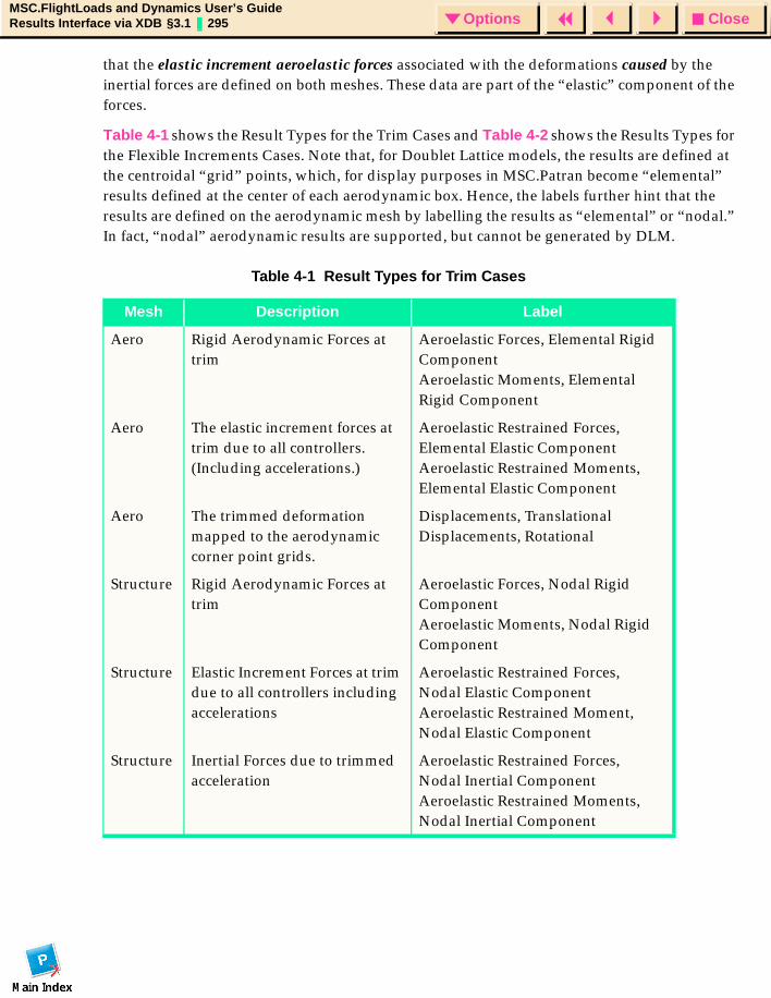
CloseOptionsMSC.FlightLoads and Dynamics User’s GuideResults Interface via XDB §3.1 295 Options
that the elastic increment aeroelastic forces associated with the deformations caused by the inertial forces are defined on both meshes. These data are part of the “elastic” component of the forces.
Table 4-1 shows the Result Types for the Trim Cases and Table 4-2 shows the Results Types for the Flexible Increments Cases. Note that, for Doublet Lattice models, the results are defined at the centroidal “grid” points, which, for display purposes in MSC.Patran become “elemental” results defined at the center of each aerodynamic box. Hence, the labels further hint that the results are defined on the aerodynamic mesh by labelling the results as “elemental” or “nodal.” In fact, “nodal” aerodynamic results are supported, but cannot be generated by DLM.
Table 4-1 Result Types for Trim Cases
Mesh Description Label
Aero Rigid Aerodynamic Forces at trim
Aeroelastic Forces, Elemental Rigid ComponentAeroelastic Moments, Elemental Rigid Component
Aero The elastic increment forces at trim due to all controllers. (Including accelerations.)
Aeroelastic Restrained Forces, Elemental Elastic ComponentAeroelastic Restrained Moments, Elemental Elastic Component
Aero The trimmed deformation mapped to the aerodynamic corner point grids.
Displacements, TranslationalDisplacements, Rotational
Structure Rigid Aerodynamic Forces at trim
Aeroelastic Forces, Nodal Rigid ComponentAeroelastic Moments, Nodal Rigid Component
Structure Elastic Increment Forces at trim due to all controllers including accelerations
Aeroelastic Restrained Forces,Nodal Elastic ComponentAeroelastic Restrained Moment,Nodal Elastic Component
Structure Inertial Forces due to trimmed acceleration
Aeroelastic Restrained Forces,Nodal Inertial ComponentAeroelastic Restrained Moments,Nodal Inertial Component
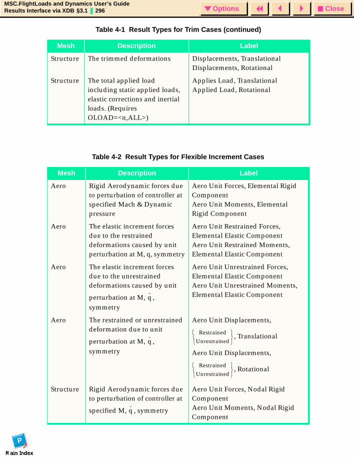
CloseOptionsMSC.FlightLoads and Dynamics User’s GuideResults Interface via XDB §3.1 296 Options
Structure The trimmed deformations Displacements, TranslationalDisplacements, Rotational
Structure The total applied load including static applied loads, elastic corrections and inertial loads. (Requires OLOAD=<n,ALL>)
Applies Load, TranslationalApplied Load, Rotational
Table 4-2 Result Types for Flexible Increment Cases
Mesh Description Label
Aero Rigid Aerodynamic forces due to perturbation of controller at specified Mach & Dynamic pressure
Aero Unit Forces, Elemental Rigid ComponentAero Unit Moments, Elemental Rigid Component
Aero The elastic increment forces due to the restrained deformations caused by unit perturbation at M, q, symmetry
Aero Unit Restrained Forces, Elemental Elastic ComponentAero Unit Restrained Moments, Elemental Elastic Component
Aero The elastic increment forces due to the unrestrained deformations caused by unit
perturbation at M, , symmetry
Aero Unit Unrestrained Forces, Elemental Elastic ComponentAero Unit Unrestrained Moments, Elemental Elastic Component
Aero The restrained or unrestrained deformation due to unit
perturbation at M, , symmetry
Aero Unit Displacements,
, Translational
Aero Unit Displacements,
, Rotational
Structure Rigid Aerodynamic forces due to perturbation of controller at
specified M, , symmetry
Aero Unit Forces, Nodal Rigid ComponentAero Unit Moments, Nodal Rigid Component
Table 4-1 Result Types for Trim Cases (continued)
Mesh Description Label
q
qRestrained
Unrestrained
Restrained
Unrestrained
q
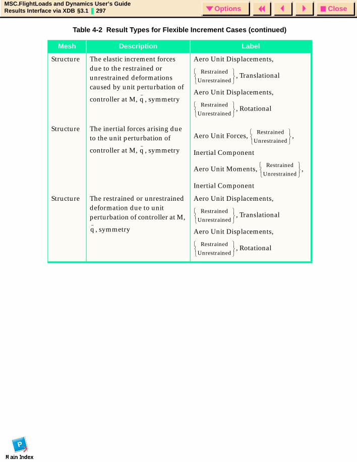
CloseOptionsMSC.FlightLoads and Dynamics User’s GuideResults Interface via XDB §3.1 297 Options
Structure The elastic increment forces due to the restrained or unrestrained deformations caused by unit perturbation of
controller at M, , symmetry
Aero Unit Displacements,
, Translational
Aero Unit Displacements,
, Rotational
Structure The inertial forces arising due to the unit perturbation of
controller at M, , symmetry
Aero Unit Forces, ,
Inertial Component
Aero Unit Moments, ,
Inertial Component
Structure The restrained or unrestrained deformation due to unit perturbation of controller at M,
, symmetry
Aero Unit Displacements,
, Translational
Aero Unit Displacements,
, Rotational
Table 4-2 Result Types for Flexible Increment Cases (continued)
Mesh Description Label
q
Restrained
Unrestrained
Restrained
Unrestrained
q
Restrained
Unrestrained
Restrained
Unrestrained
q
Restrained
Unrestrained
Restrained
Unrestrained

CloseOptionsMSC.FlightLoads and Dynamics User’s GuideResults Interface via XDB §3.1 298 Options

CloseOptionsMSC.FlightLoads and Dynamics User’s GuideAerodynamic and Aeroelastic Databases § 299 Options
MSC.FlightLoads and Dynamics User’s Guide
APPENDIX
D Aerodynamic and Aeroelastic Databases
Aerodynamic and Aeroelastic Databases

CloseOptionsMSC.FlightLoads and Dynamics User’s GuideAerodynamic and Aeroelastic Databases § 300 Options
Aerodynamic and Aeroelastic DatabasesWhile MSC.Nastran has a very sophisticated automated restart capability, in aeroelastic analysis, it is often the case that the aerodynamic data are updated relatively infrequently relative to the structural data. Also, once the computationally intensive unit solutions are obtained, they can be reused in TRIM analysis very rapidly (nearly interactively) to generate distributed trimmed loads.
While MSC.Nastran’s NDDL, FMS and DMAP have always allowed the reuse of these data, it was not a trivial matter to define the collection of datablocks that would constitute the minimal archival set for reuse that also had the appropriate functionality (supply all the requisite pieces). Further, to reuse the data blocks (as opposed to automated restart), the DMAP needs to “look” for the data blocks and, if already present, explicitly branch around the “creation” step.
In MSC.Nastran V70.7 (as part of the FlightLoads development), the NDDL and DMAPs associated with SOL 144 were updated to create two collections of data: an aerodynamic database and an aeroelastic database. These collections are implemented in such a way as to simplify the user input requirements, remain compatible with automated restart and allow data “reuse” using the DBLOCATE technique.
The modifications made are primarily in DMAP and, in particular, NDDL. A hierarchy of aerodynamic and aeroelastic paths was defined in NDDL that allows the user to archive and reuse the aerodynamic and aeroelastic data (somewhat independently). This is accomplished by created two new LOCATION values in the NDDL (and DMAP): the ADB and the AEDB. Aerodynamic data (completely independent of structural data) is associated with the ADB and aeroelastic data (coupling a particular aerodynamic model with the current structure and/or structural boundary condition) is associated with the AEDB. To direct the aerodynamic data onto a particular DBSET, one simply adds the appropriate INIT and ASSIGN statements and includes in bulk data the definition of the location parameters (PARAM,ADB,logical_adb_name).
PathsA hierarchy of paths has been established for aerodynamic and aeroelastic data. These paths start at a minimal set at the top level and expand in scope as we move lower in the hierarchy. The top level is “geometry,” recognizing that the user has ultimate control and may choose any relationship among disparate instances at this level. In other words, two distinct “geometries” may be the same vehicle with differing mesh topologies or it may be completely unrelated data or even duplicate data.
While the NDDL language cannot support PATHs that include other PATHs, the PATHs will be shown as additions to or unions with other PATHs to facilitate understanding of the hierarchy. In NDDL, they are, of necessity, expanded.
For aerodynamic data, the basic path is:
path aegeom aeconfig,symxy,symxz,APRCH,HIGHQUAL $path aegeomf modltype + aegeom $
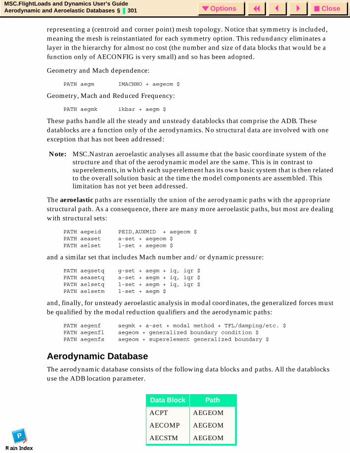
CloseOptionsMSC.FlightLoads and Dynamics User’s GuideAerodynamic and Aeroelastic Databases § 301 Options
representing a (centroid and corner point) mesh topology. Notice that symmetry is included, meaning the mesh is reinstantiated for each symmetry option. This redundancy eliminates a layer in the hierarchy for almost no cost (the number and size of data blocks that would be a function only of AECONFIG is very small) and so has been adopted.
Geometry and Mach dependence:
PATH aegm IMACHNO + aegeom $
Geometry, Mach and Reduced Frequency:
PATH aegmk ikbar + aegm $
These paths handle all the steady and unsteady datablocks that comprise the ADB. These datablocks are a function only of the aerodynamics. No structural data are involved with one exception that has not been addressed:
Note: MSC.Nastran aeroelastic analyses all assume that the basic coordinate system of the structure and that of the aerodynamic model are the same. This is in contrast to superelements, in which each superelement has its own basic system that is then related to the overall solution basic at the time the model components are assembled. This limitation has not yet been addressed.
The aeroelastic paths are essentially the union of the aerodynamic paths with the appropriate structural path. As a consequence, there are many more aeroelastic paths, but most are dealing with structural sets:
PATH aepeid PEID,AUXMID + aegeom $PATH aeaset a-set + aegeom $PATH aelset l-set + aegeom $
and a similar set that includes Mach number and/or dynamic pressure:
PATH aegsetq g-set + aegm + iq, iqr $PATH aeasetq a-set + aegm + iq, iqr $PATH aelsetq l-set + aegm + iq, iqr $PATH aelsetm l-set + aegm $
and, finally, for unsteady aeroelastic analysis in modal coordinates, the generalized forces must be qualified by the modal reduction qualifiers and the aerodynamic paths:
PATH aegenf aegmk + a-set + modal method + TFL/damping/etc. $PATH aegenfl aegeom + generalized boundary condition $PATH aegenfs aegeom + superelement generalized boundary $
Aerodynamic DatabaseThe aerodynamic database consists of the following data blocks and paths. All the datablocks use the ADB location parameter.
Data Block Path
ACPT AEGEOM
AECOMP AEGEOM
AECSTM AEGEOM
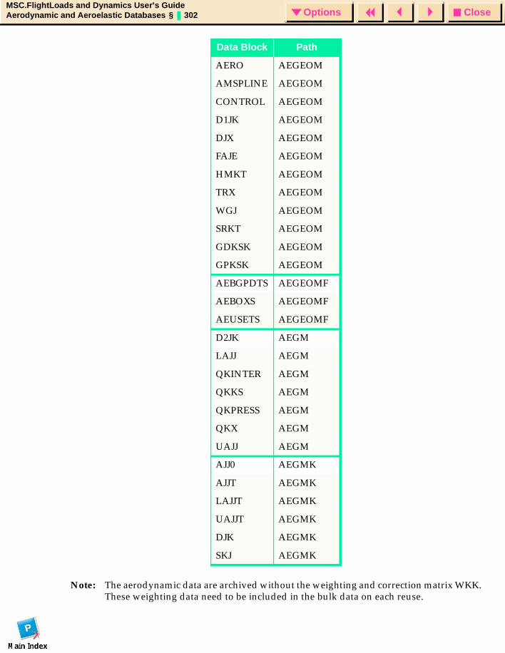
CloseOptionsMSC.FlightLoads and Dynamics User’s GuideAerodynamic and Aeroelastic Databases § 302 Options
Note: The aerodynamic data are archived without the weighting and correction matrix WKK. These weighting data need to be included in the bulk data on each reuse.
AERO AEGEOM
AMSPLINE AEGEOM
CONTROL AEGEOM
D1JK AEGEOM
DJX AEGEOM
FAJE AEGEOM
HMKT AEGEOM
TRX AEGEOM
WGJ AEGEOM
SRKT AEGEOM
GDKSK AEGEOM
GPKSK AEGEOM
AEBGPDTS AEGEOMF
AEBOXS AEGEOMF
AEUSETS AEGEOMF
D2JK AEGM
LAJJ AEGM
QKINTER AEGM
QKKS AEGM
QKPRESS AEGM
QKX AEGM
UAJJ AEGM
AJJ0 AEGMK
AJJT AEGMK
LAJJT AEGMK
UAJJT AEGMK
DJK AEGMK
SKJ AEGMK
Data Block Path
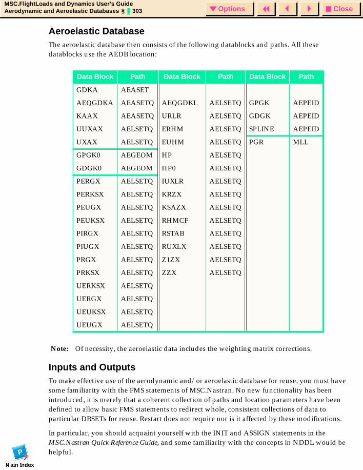
CloseOptionsMSC.FlightLoads and Dynamics User’s GuideAerodynamic and Aeroelastic Databases § 303 Options
Aeroelastic DatabaseThe aeroelastic database then consists of the following datablocks and paths. All these datablocks use the AEDB location:
Note: Of necessity, the aeroelastic data includes the weighting matrix corrections.
Inputs and OutputsTo make effective use of the aerodynamic and/or aeroelastic database for reuse, you must have some familiarity with the FMS statements of MSC.Nastran. No new functionality has been introduced, it is merely that a coherent collection of paths and location parameters have been defined to allow basic FMS statements to redirect whole, consistent collections of data to particular DBSETs for reuse. Restart does not require nor is it affected by these modifications.
In particular, you should acquaint yourself with the INIT and ASSIGN statements in the MSC.Nastran Quick Reference Guide, and some familiarity with the concepts in NDDL would be helpful.
Data Block Path Data Block Path Data Block Path
GDKA AEASET
AEQGDKA AEASETQ AEQGDKL AELSETQ GPGK AEPEID
KAAX AEASETQ URLR AELSETQ GDGK AEPEID
UUXAX AELSETQ ERHM AELSETQ SPLINE AEPEID
UXAX AELSETQ EUHM AELSETQ PGR MLL
GPGK0 AEGEOM HP AELSETQ
GDGK0 AEGEOM HP0 AELSETQ
PERGX AELSETQ IUXLR AELSETQ
PERKSX AELSETQ KRZX AELSETQ
PEUGX AELSETQ KSAZX AELSETQ
PEUKSX AELSETQ RHMCF AELSETQ
PIRGX AELSETQ RSTAB AELSETQ
PIUGX AELSETQ RUXLX AELSETQ
PRGX AELSETQ Z1ZX AELSETQ
PRKSX AELSETQ ZZX AELSETQ
UERKSX AELSETQ
UERGX AELSETQ
UEUKSX AELSETQ
UEUGX AELSETQ
CloseOptionsMSC.FlightLoads and Dynamics User’s GuideAerodynamic and Aeroelastic Databases § 304 Options
In the Bulk Data Section, you must define the ADB and AEDB location PARAMETERs (which are just PARAMs, like any other) to have the logical name of the DBSET to which you want the aerodynamic and aeroelastic (respectively) datablocks to be placed. These PARAMs are only needed on the job submittal(s) that create(s) the database.
To create both an aerodynamic and aeroelastic database, for example:
INIT, MASTER, LOGICAL=(MASTER(1000MB))ASSIGN MASTER=’adb144.master’INIT, DBALL, LOGICAL=(DBALL1(1000MB))ASSIGN DBALL1=’adb144.dball’INIT, myADB, LOGICAL=(myADB(1000MB))ASSIGN myADB=’adb144.adb’INIT, myAEDB, LOGICAL=(myAEDB(1000MB))ASSIGN myAEDB=’adb144.aedb’...BEGIN BULKparam,adb,myadbparam,aedb,myaedb...
In the case of multiple instances (an instance is a single data block that is associated with a particular set of qualifiers) of the datablocks on the aerodynamic or aeroelastic database, all of them will be located onto the DBSETs associated with the ADB and AEDB parameters.
To reuse an existing database, you need only ASSIGN the MASTER file and DBLOCATE all data blocks and parameters
ASSIGN AeroDB=’adb144.master’dblocate where (dbset=’myadb’ or dbset=’myaedb’) logical=aerodb
In the case of reuse (using DBLOCATE), the DBALL component of the initial database can be deleted (it then appears “offline” to the reuse, but there are no components on DBALL that are required for the reuse). The MASTER and ADB must be saved and DBLOCATEd to reuse the aerodynamic model. The MASTER, ADB and AEDB must be saved and DBLOCATEd to reuse the aeroelastic data.
Note: For MSC.Nastran to “find” the data blocks on the database, the set of qualifiers (the “path”) of the required data blocks in the reuse job must EXACTLY match those on the archived database. Be careful that the AECONFIG name (the only completely arbitrary value in the path) is the same. Also, if the Mach or Dynamic pressure is not found, new computations will occur without warning. This is really a feature since this is usually what you want to do: reuse the existing aerodynamic geometry and compute new rigid data. Further, you can “append” to the database by using the PARAM, ADB or PARAM, AEDB in conjunction with the DBLOCATE to create a new MASTER that includes both the original database and the new datablocks. This extension can be continued indefinitely.
CloseOptionsMSC.FlightLoads and Dynamics User’s GuideAerodynamic and Aeroelastic Databases § 305 Options
Guidelines and LimitationsBe aware that the aerodynamic datablocks (in particular QKK and AJJ matrices) are fully dense (subsonic) and unsymmetrical. Consequently, the DBSETs of the aerodynamic and aeroelastic database may become very large. Archiving data for reuse is effective only when the tradeoffs between computational expense and data storage requirements are such that you want to store the data. These data are both large and computationally intensive to create, so typically archiving for reuse only makes sense if you know you intend to reuse the data.
In MSC.Nastran V70.7, the aeroelastic database is only defined for the static aeroelastic problem. The aerodynamic database, on the other hand, is defined for both the steady and unsteady data for all aerodynamic theories.
ExamplesA number of examples of both the aerodynamic database and aeroelastic database are included in the TPL. Because they are database creation and reuse examples, the order in which you execute the samples is important. In the procs directory of the MSC.Nastran delivery, there is a procedure aero_db.com that can be used to execute the tests in the appropriate order and performing the appropriate clean up between multiple executions. The following bullets list the samples in order of intended execution and describe the feature illustrated by the example:
1. adb144_1: Perform a static aeroelastic analysis and save the ADB and AEDB components for reuse.
2. adb144r1: Replicate adb144_1, reusing the ADB and AEDB components. The original aerodynamic model and spline (aeroelastic) model is described in bulk data, but these data are not used in the run.
3. adb144r2: Replicate adb144_1, reusing the ADB and AEDB components but, this input deck doesn’t include any aerodynamic model. The entire aeroelastic model is retrieved from the archived database. (This is the case in adb144r1 also, but the original bulk data was left in place to show that its presence doesn’t affect the run.)
4. adb144r3: Replicate adb144_1, reusing the ADB and AEDB components but neither the aerodynamic model nor the spline data are present in the input stream. This illustrates that the full aeroelastic model is retrieved from the ADB/AEDB and the bulk data is not used.
5. adb144_2: Create a new aerodynamic and aeroelastic data base by attaching the original from adb144_1, but utilizing a new configuration name and/or new Mach number/dynamic pressures, “append” new data to the database. The MASTER from this run can subsequently be attached and ADB, AEDB datablocks DBLOCATEd and both models will be available for reuse.
6. dumpadb: This illustrates a mini-DMAP solution that attaches an aerodynamic database and dumps rigid aerodynamic data to the XDB that allows visualization of the aerodynamic data. No data on the structural mesh is dumped, because the structural geometry/connectivity is not on the ADB or AEDB components, so XDB cannot associate the data to grids/elements.

CloseOptionsMSC.FlightLoads and Dynamics User’s GuideAerodynamic and Aeroelastic Databases § 306 Options
7. dumpaedb: Similar to dumpadb, but includes the aeroelastic unit solution data. In this case, the aeroelastic data on the aerodynamic mesh are dumped to the XDB (in addition to the rigid aerodynamics). No data on the structural mesh is dumped, because the structural geometry/connectivity is not on the ADB or AEDB components, so XDB cannot associate the data to grids/elements.
8. adb145_1: This deck generates an unsteady aerodynamic database and also performs flutter analysis at a single Mach and altitude.
9. adb145r1: This deck reuses the unsteady aerodynamic database of adb145_1 to perform a complete Mach and altitude sweep for the archived Mach numbers.

CloseOptionsMSC.FlightLoads and Dynamics User’s GuideStatic Aeroelastic Analysis § 307 Options
MSC.FlightLoads and Dynamics User’s Guide
APPENDIX
E Static Aeroelastic Analysis
Introduction
Aeroelastic Matrices
Aeroelastic Solutions
Printed Output

CloseOptionsMSC.FlightLoads and Dynamics User’s GuideStatic Aeroelastic Analysis § 308 Options
IntroductionPanel Aerodynamics (App. A) has discussed the aerodynamic methods contained in FlightLoads while Splines (App. B) has detailed how the aerodynamic and structural models are connected. This appendix completes the description of the computationally intensive portion of MSC.FlightLoads and Dynamics by documenting how these components are used in a static aeroelastic analysis.
As depicted in Analysis (p. 161), the static aeroelastic analysis consists of three methods:
• Flexible Increments
• Flexible Trim
• Rigid Trim
After setting up the governing matrix equations, this appendix provides a discussion of these three methods. In this discussion, the term "unit solutions" is used interchangeably with the "Flexible Increments" method.
A very useful by-product of the aeroelastic analysis is the production of stability derivative and hinge moment data. This information is created within MSC.Nastran and is printed within the output (.f06) file. Although the information is not available as part of FlightLoads postprocessing, its value motivates the documentation of it here. (The dimensional equivalents can be obtained from the Load Summation tool of the Loads Browser).
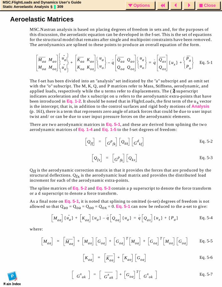
CloseOptionsMSC.FlightLoads and Dynamics User’s GuideStatic Aeroelastic Analysis § 309 Options
Aeroelastic MatricesMSC.Nastran analysis is based on placing degrees of freedom in sets and, for the purposes of this discussion, the aeroelastic equation can be developed in the f-set. This is the set of equations for the structural model that remains after single and multipoint constraints have been removed. The aerodynamics are splined to these points to produce an overall equation of the form.
Eq. 5-1
The f-set has been divided into an "analysis" set indicated by the "a" subscript and an omit set with the "o" subscript. The M, K, Q, and P matrices refer to Mass, Stiffness, aerodynamic, and applied loads, respectively while the u terms refer to displacements. The ( ŽŽ ) superscript indicates acceleration and the x subscript on u refers to the aerodynamic extra-points that have been introduced in Eq. 1-2. It should be noted that in FlightLoads, the first term of the ux vector is the intercept; that is, in addition to the control surfaces and rigid body motions of Analysis (p. 161), there is a term that represents zero angle of attack forces that could be due to user input twist and/or can be due to user input pressure forces on the aerodynamic elements.
There are two aerodynamic matrices in Eq. 5-1, and these are derived from splining the two aerodynamic matrices of Eq. 1-4 and Eq. 1-5 to the f-set degrees of freedom:
Eq. 5-2
Eq. 5-3
Qff is the aerodynamic correction matrix in that it provides the forces that are produced by the structural deflections. Qfx is the aerodynamic load matrix and provides the distributed load increment for each of the aerodynamic extra-points.
The spline matrices of Eq. 5-2 and Eq. 5-3 contain a p superscript to denote the force transform or a d superscript to denote a force transform.
As a final note on Eq. 5-1, it is noted that splining to omitted (o-set) degrees of freedom is not allowed so that Qao = Qoa = Qoo = Qox = 0. Eq. 5-1 can now be reduced to the a-set to give:
Eq. 5-4
where:
Eq. 5-5
Eq. 5-6
Eq. 5-7
Maa Mao
Moa Moo
ua··
uo··
Kaa Kao
Koa Koo
ua
uo
qQaa Qao
Qoa Qoo
ua
uo
qQax
Qox
ux Pa
Po
+=–+
Qff Gp
fkQkk G
dkf
=
Qfx Gp
fkQkx=
Maa ua·· Kaa ua q Qaa ua q Qax ux Pa +=–+
Maa MaaMao Goa Goa
TMoa Goa
TMoo Goa+ + +=
Kaa KaaKao Goa+=
Gx
ak Gx
akGoa
TG
xok
+=
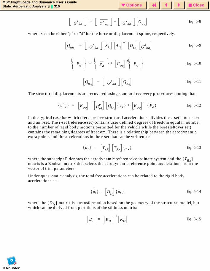
CloseOptionsMSC.FlightLoads and Dynamics User’s GuideStatic Aeroelastic Analysis § 310 Options
Eq. 5-8
where x can be either "p" or "d" for the force or displacement spline, respectively.
Eq. 5-9
Eq. 5-10
Eq. 5-11
The structural displacements are recovered using standard recovery procedures; noting that
Eq. 5-12
In the typical case for which there are free structural accelerations, divides the a-set into a r-set and an l-set. The r-set (reference set) contains user defined degrees of freedom equal in number to the number of rigid body motions permitted for the vehicle while the l-set (leftover set) contains the remaining degrees of freedom. There is a relationship between the aerodynamic extra points and the accelerations in the r-set that can be written as:
Eq. 5-13
where the subscript R denotes the aerodynamic reference coordinate system and the matrix is a Boolean matrix that selects the aerodynamic reference point accelerations from the vector of trim parameters.
Under quasi-static analysis, the total free accelerations can be related to the rigid body accelerations as:
Eq. 5-14
where the matrix is a transformation based on the geometry of the structural model, but which can be derived from partitions of the stiffness matrix:
Eq. 5-15
Gx
ka Gx
ka Gx
koGoa+=
Qaa Gp
kaSkj Ajj
1–Djk G
dka
=
Pa
Pa
GoaT
Po
+=
Qax Gp
kaQkx=
uoo Koo
1–Gok
p Qkx ux Koo+1–
Po =
ur·· TrR TRx ux =
TRx[ ]
u··
l Dlr u··
r =
Dlr[ ]
Dlr Kll
1–Klr=
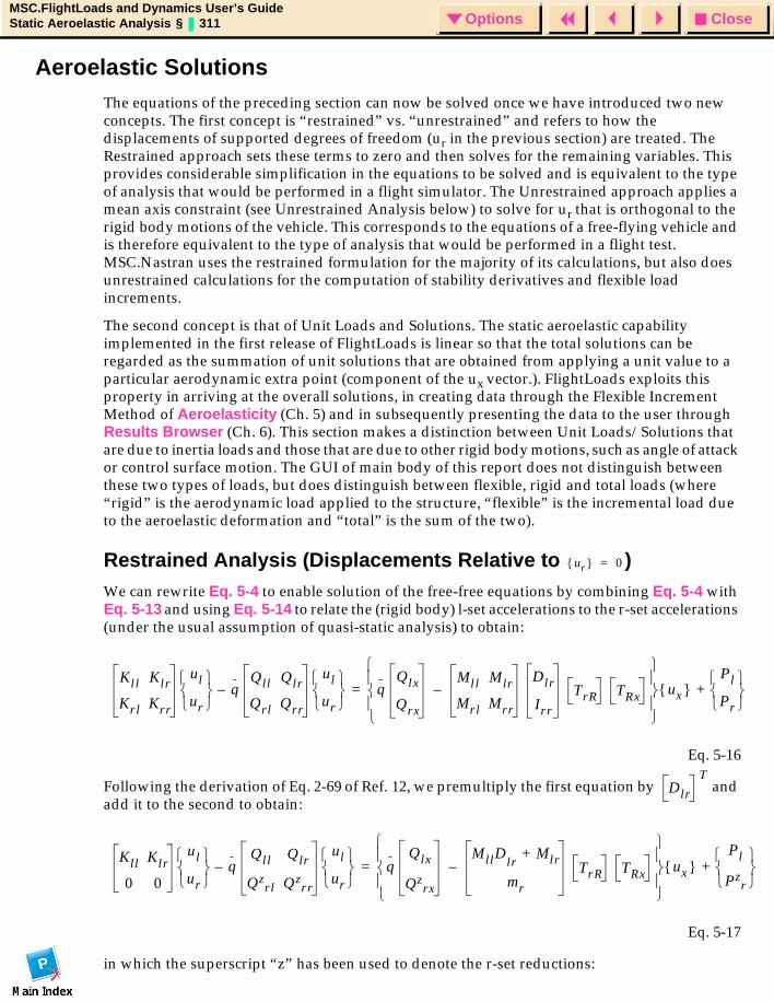
CloseOptionsMSC.FlightLoads and Dynamics User’s GuideStatic Aeroelastic Analysis § 311 Options
Aeroelastic Solutions The equations of the preceding section can now be solved once we have introduced two new concepts. The first concept is “restrained” vs. “unrestrained” and refers to how the displacements of supported degrees of freedom (ur in the previous section) are treated. The Restrained approach sets these terms to zero and then solves for the remaining variables. This provides considerable simplification in the equations to be solved and is equivalent to the type of analysis that would be performed in a flight simulator. The Unrestrained approach applies a mean axis constraint (see Unrestrained Analysis below) to solve for ur that is orthogonal to the rigid body motions of the vehicle. This corresponds to the equations of a free-flying vehicle and is therefore equivalent to the type of analysis that would be performed in a flight test. MSC.Nastran uses the restrained formulation for the majority of its calculations, but also does unrestrained calculations for the computation of stability derivatives and flexible load increments.
The second concept is that of Unit Loads and Solutions. The static aeroelastic capability implemented in the first release of FlightLoads is linear so that the total solutions can be regarded as the summation of unit solutions that are obtained from applying a unit value to a particular aerodynamic extra point (component of the ux vector.). FlightLoads exploits this property in arriving at the overall solutions, in creating data through the Flexible Increment Method of Aeroelasticity (Ch. 5) and in subsequently presenting the data to the user through Results Browser (Ch. 6). This section makes a distinction between Unit Loads/Solutions that are due to inertia loads and those that are due to other rigid body motions, such as angle of attack or control surface motion. The GUI of main body of this report does not distinguish between these two types of loads, but does distinguish between flexible, rigid and total loads (where “rigid” is the aerodynamic load applied to the structure, “flexible” is the incremental load due to the aeroelastic deformation and “total” is the sum of the two).
Restrained Analysis (Displacements Relative to )We can rewrite Eq. 5-4 to enable solution of the free-free equations by combining Eq. 5-4 with Eq. 5-13 and using Eq. 5-14 to relate the (rigid body) l-set accelerations to the r-set accelerations (under the usual assumption of quasi-static analysis) to obtain:
Eq. 5-16
Following the derivation of Eq. 2-69 of Ref. 12, we premultiply the first equation by and add it to the second to obtain:
Eq. 5-17
in which the superscript “z” has been used to denote the r-set reductions:
ur 0=
Kll Klr
Krl Krr
ul
ur
qQll Qlr
Qrl Qrr
ul
ur
qQlx
Qrx
Mll Mlr
Mrl Mrr
Dlr
Irr
TrR TRx–
ux Pl
Pr
+=–
Dlr
T
Kll Klr
0 0
ul
ur
qQll Qlr
Qzrl Qz
rr
ul
ur
qQlx
Qzrx
MllDlrMlr+
mr
TrR TRx–
ux Pl
Pzr
+=–
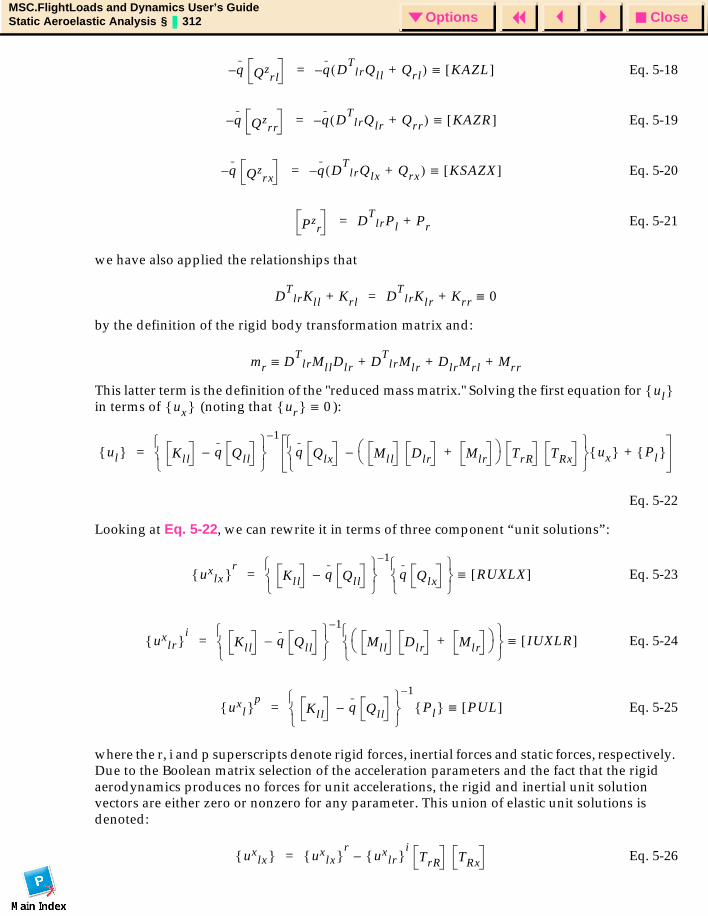
CloseOptionsMSC.FlightLoads and Dynamics User’s GuideStatic Aeroelastic Analysis § 312 Options
Eq. 5-18
Eq. 5-19
Eq. 5-20
Eq. 5-21
we have also applied the relationships that
by the definition of the rigid body transformation matrix and:
This latter term is the definition of the "reduced mass matrix." Solving the first equation for in terms of (noting that ):
Eq. 5-22
Looking at Eq. 5-22, we can rewrite it in terms of three component “unit solutions”:
Eq. 5-23
Eq. 5-24
Eq. 5-25
where the r, i and p superscripts denote rigid forces, inertial forces and static forces, respectively. Due to the Boolean matrix selection of the acceleration parameters and the fact that the rigid aerodynamics produces no forces for unit accelerations, the rigid and inertial unit solution vectors are either zero or nonzero for any parameter. This union of elastic unit solutions is denoted:
Eq. 5-26
q– Qzrl
q DT
lrQll Q+ rl( )– KAZL[ ]≡=
q– Qzrr
q DT
lrQlr Q+ rr( )– KAZR[ ]≡=
q– Qzrx
q– DT
lrQlx Q+ rx( ) KSAZX[ ]≡=
Pzr
DT
lrPl P+ r=
DT
lrKll K+ rl DT
lrKlr K+ rr 0≡=
mr DT
lrMllDlr DT
lrM+ lr DlrMrl Mrr+ +≡
ul ux ur 0≡
ul Kll q Qll– 1–
q Qlx Mll Dlr Mlr+ TrR TRx–
ux Pl +=
uxlx
rKll q Qll–
1–
q Qlx
RUXLX[ ]≡=
uxlr
iKll q Qll–
1–
Mll Dlr Mlr+
IUXLR[ ]≡=
uxl
pKll q Qll–
1–
Pl PUL[ ]≡=
uxlx ux
lx r
uxlr
iTrR TRx–=
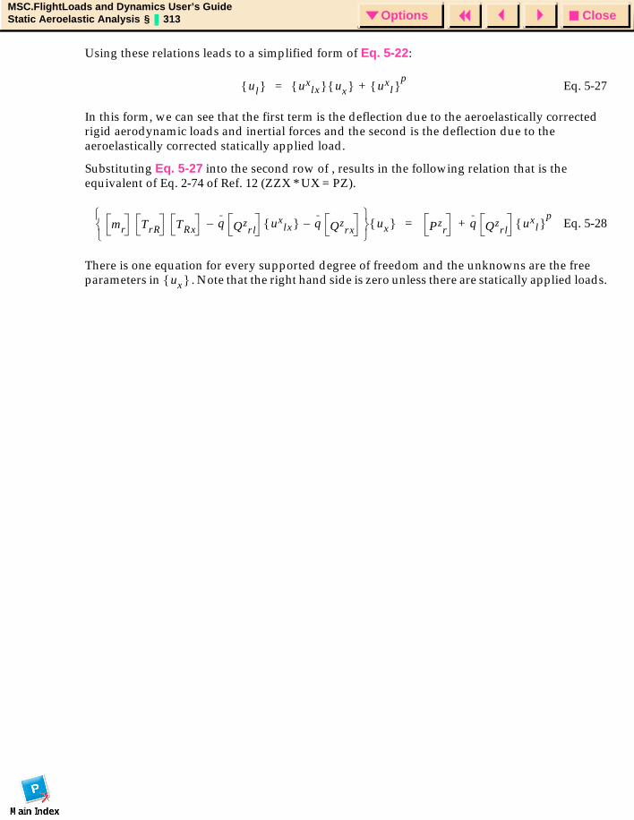
CloseOptionsMSC.FlightLoads and Dynamics User’s GuideStatic Aeroelastic Analysis § 313 Options
Using these relations leads to a simplified form of Eq. 5-22:
Eq. 5-27
In this form, we can see that the first term is the deflection due to the aeroelastically corrected rigid aerodynamic loads and inertial forces and the second is the deflection due to the aeroelastically corrected statically applied load.
Substituting Eq. 5-27 into the second row of , results in the following relation that is the equivalent of Eq. 2-74 of Ref. 12 (ZZX * UX = PZ).
Eq. 5-28
There is one equation for every supported degree of freedom and the unknowns are the free parameters in . Note that the right hand side is zero unless there are statically applied loads.
ul uxlx ux ux
l p
+=
mr TrR TRx q Qzrl
– uxlx q Qz
rx–
ux Pzr
q Qzrl
uxl
p+=
ux
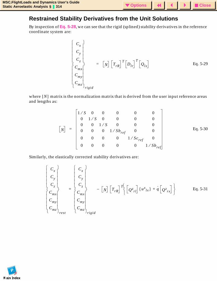
CloseOptionsMSC.FlightLoads and Dynamics User’s GuideStatic Aeroelastic Analysis § 314 Options
Restrained Stability Derivatives from the Unit SolutionsBy inspection of Eq. 5-28, we can see that the rigid (splined) stability derivatives in the reference coordinate system are:
Eq. 5-29
where matrix is the normalization matrix that is derived from the user input reference areas and lengths as:
Eq. 5-30
Similarly, the elastically corrected stability derivatives are:
Eq. 5-31
Cx
Cy
Cz
Cmx
Cmy
Cmz
rigid
N TrRT
Dlr
TQlx=
N[ ]
N
1 S⁄ 0 0 0 0 00 1 S⁄ 0 0 0 00 0 1 S⁄ 0 0 00 0 0 1 Sbref⁄ 0 0
0 0 0 0 1 Scref⁄ 0
0 0 0 0 0 1 Sbref⁄
=
Cx
Cy
Cz
Cmx
Cmy
Cmz
rest
Cx
Cy
Cz
Cmx
Cmy
Cmz
rigid
N– TrRT
Qzrl
uxlx q Qz
rx+
=
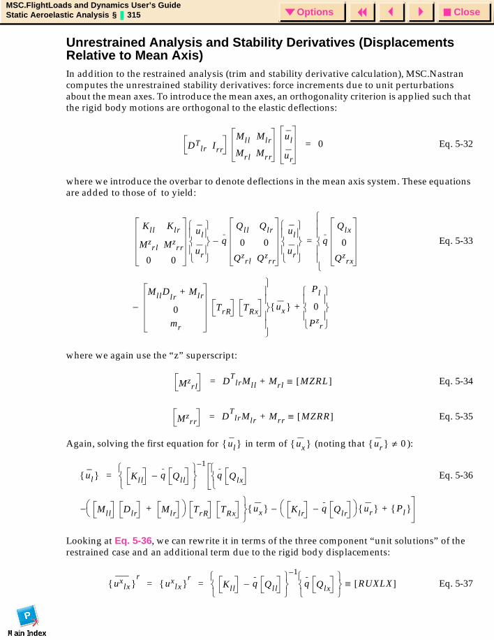
CloseOptionsMSC.FlightLoads and Dynamics User’s GuideStatic Aeroelastic Analysis § 315 Options
Unrestrained Analysis and Stability Derivatives (Displacements Relative to Mean Axis)In addition to the restrained analysis (trim and stability derivative calculation), MSC.Nastran computes the unrestrained stability derivatives: force increments due to unit perturbations about the mean axes. To introduce the mean axes, an orthogonality criterion is applied such that the rigid body motions are orthogonal to the elastic deflections:
Eq. 5-32
where we introduce the overbar to denote deflections in the mean axis system. These equations are added to those of to yield:
Eq. 5-33
where we again use the “z” superscript:
Eq. 5-34
Eq. 5-35
Again, solving the first equation for in term of (noting that ):
Eq. 5-36
Looking at Eq. 5-36, we can rewrite it in terms of the three component “unit solutions” of the restrained case and an additional term due to the rigid body displacements:
Eq. 5-37
DTlr Irr
Mll Mlr
Mrl Mrr
ul
ur
0=
Kll Klr
Mzrl Mz
rr
0 0
ul
ur
q
Qll Qlr
0 0
Qzrl Qz
rr
ul
ur
q
Qlx
0
Qzrx
MllDlrMlr+
0mr
TrR TRx–
ux
Pl
0
Pzr
+
=–
Mzrl
DT
lrMll M+ rl MZRL[ ]≡=
Mzrr
DT
lrMlr M+ rr MZRR[ ]≡=
ul ux ur 0≠
ul Kll q Qll– 1–
q Qlx
Mll Dlr Mlr+ TrR TRx–
ux Klr q Qlr–
ur Pl +–
=
uxlx
rux
lx r
Kll q Qll– 1–
q Qlx
RUXLX[ ]≡= =
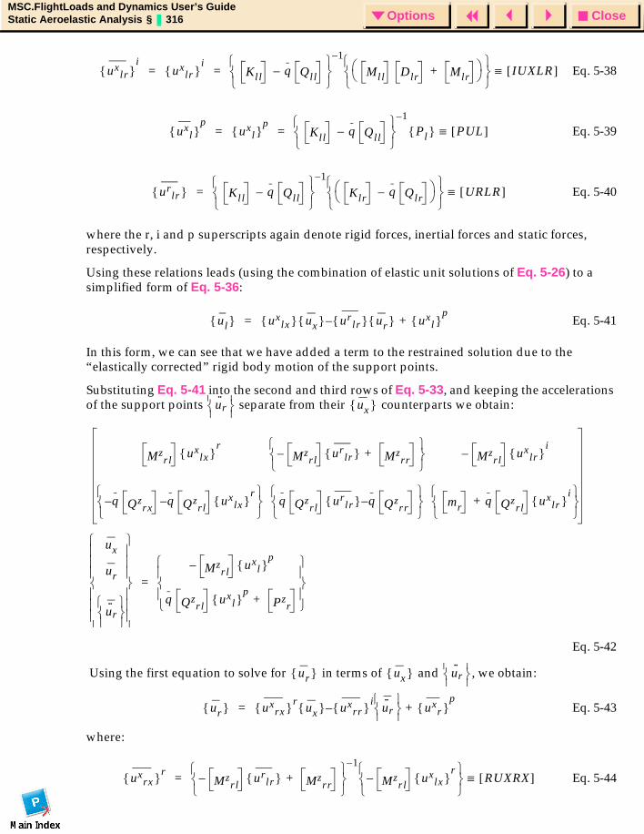
CloseOptionsMSC.FlightLoads and Dynamics User’s GuideStatic Aeroelastic Analysis § 316 Options
Eq. 5-38
Eq. 5-39
Eq. 5-40
where the r, i and p superscripts again denote rigid forces, inertial forces and static forces, respectively.
Using these relations leads (using the combination of elastic unit solutions of Eq. 5-26) to a simplified form of Eq. 5-36:
Eq. 5-41
In this form, we can see that we have added a term to the restrained solution due to the “elastically corrected” rigid body motion of the support points.
Substituting Eq. 5-41 into the second and third rows of Eq. 5-33, and keeping the accelerations of the support points separate from their counterparts we obtain:
Eq. 5-42
Using the first equation to solve for in terms of and , we obtain:
Eq. 5-43
where:
Eq. 5-44
uxlr
iux
lr i
Kll q Qll– 1–
Mll Dlr Mlr+
IUXLR[ ]≡= =
uxl
pux
l p
Kll q Qll– 1–
Pl PUL[ ]≡= =
urlr Kll q Qll–
1–
Klr q Qlr–
URLR[ ]≡=
ul uxlx ux ur
lr – ur uxl
p+=
u··
r
ux
Mzrl
uxlx
rMz
rl– ur
lr Mzrr
+
Mzrl
uxlr
i–
q Qzrx
q Qzrl
uxlx
r––
q Qzrl
urlr q Qz
rr–
mr q Qzrl
uxlr
i+
ux
ur
u··
r
Mzrl
uxl
p–
q Qzrl
uxl
pPz
r+
=
ur ux u··
r
ur uxrx r
ux uxrr i
– u··
r
uxr
p+=
uxrx r
Mzrl
– urlr Mz
rr+
1–
Mzrl
uxlx
r–
RUXRX[ ]≡=
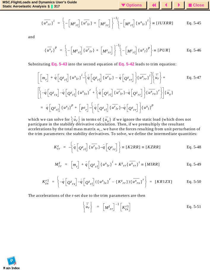
CloseOptionsMSC.FlightLoads and Dynamics User’s GuideStatic Aeroelastic Analysis § 317 Options
Eq. 5-45
and
Eq. 5-46
Substituting Eq. 5-43 into the second equation of Eq. 5-42 leads to trim equation:
Eq. 5-47
which we can solve for in terms of if we ignore the static load (which does not participate in the stability derivative calculation. Then, if we premultiply the resultant accelerations by the total mass matrix , we have the forces resulting from unit perturbation of the trim parameters: the stability derivatives. To solve, we define the intermediate quantities:
Eq. 5-48
Eq. 5-49
Eq. 5-50
The accelerations of the r-set due to the trim parameters are then
Eq. 5-51
uxrr i
Mzrl
– urlr Mz
rr+
1–
Mzrl
– uxlr
i
IUXRR[ ]≡=
uxr
pMz
rl– ur
lr Mzrr
+ 1–
Mzrl
uxl
p–
PUR[ ]≡=
mr q Qzrl
uxlr
iq Qz
rlur
lr q– Qzrr
– uxrr i
+ u··
r
q Qzrx
q Qzrl
uxlx
rq Qz
rlur
lr q– Qzrr
uxrx r
+––
ux
+
q Qzrl
uxl
pPz
rq Qz
rlur
lr q– Qzrr
– uxl
p+=
u··
r
ux
mr
Krrz q Qz
rlur
lr q– Qzrr
K2RR[ ] KZRR[ ]≡ ≡–=
MrrI mr q Qz
rlux
lr i
Kzrr ux
rr iMIRR[ ]≡+ +=
Kzxr1 q Qz
rxq Qz
rlux
lx r
Kzrr –( ) ux
rx r––
KR1ZX[ ]= =
u··
r
MIrr
1–Kzx
r1=
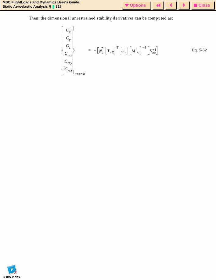
CloseOptionsMSC.FlightLoads and Dynamics User’s GuideStatic Aeroelastic Analysis § 318 Options
Then, the dimensional unrestrained stability derivatives can be computed as:
Eq. 5-52
Cx
Cy
Cz
Cmx
Cmy
Cmz
unrest·
N– TrRT
mr MIrr
1–Kzx
r1=
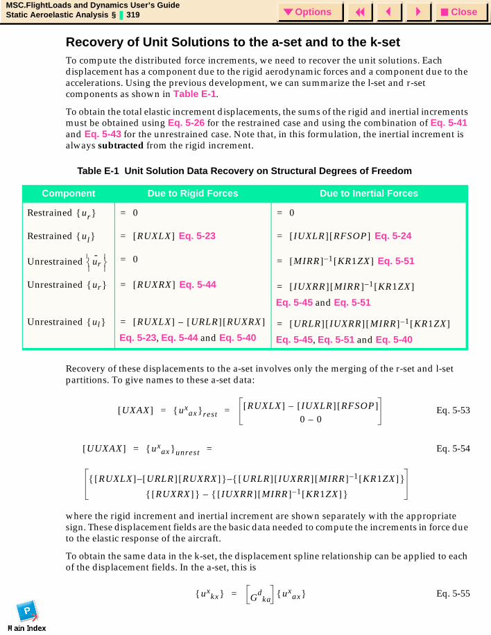
CloseOptionsMSC.FlightLoads and Dynamics User’s GuideStatic Aeroelastic Analysis § 319 Options
Recovery of Unit Solutions to the a-set and to the k-setTo compute the distributed force increments, we need to recover the unit solutions. Each displacement has a component due to the rigid aerodynamic forces and a component due to the accelerations. Using the previous development, we can summarize the l-set and r-set components as shown in Table E-1.
To obtain the total elastic increment displacements, the sums of the rigid and inertial increments must be obtained using Eq. 5-26 for the restrained case and using the combination of Eq. 5-41 and Eq. 5-43 for the unrestrained case. Note that, in this formulation, the inertial increment is always subtracted from the rigid increment.
Recovery of these displacements to the a-set involves only the merging of the r-set and l-set partitions. To give names to these a-set data:
Eq. 5-53
Eq. 5-54
where the rigid increment and inertial increment are shown separately with the appropriate sign. These displacement fields are the basic data needed to compute the increments in force due to the elastic response of the aircraft.
To obtain the same data in the k-set, the displacement spline relationship can be applied to each of the displacement fields. In the a-set, this is
Eq. 5-55
Table E-1 Unit Solution Data Recovery on Structural Degrees of Freedom
Component Due to Rigid Forces Due to Inertial Forces
Restrained
Restrained Eq. 5-23 Eq. 5-24
Unrestrained Eq. 5-51
Unrestrained Eq. 5-44
Eq. 5-45 and Eq. 5-51
Unrestrained
Eq. 5-23, Eq. 5-44 and Eq. 5-40 Eq. 5-45, Eq. 5-51 and Eq. 5-40
ur 0= 0=
ul RUXLX[ ]= IUXLR[ ] RFSOP[ ]=
u··
r 0= MIRR[ ] 1– KR1ZX[ ]=
ur RUXRX[ ]= IUXRR[ ] MIRR[ ] 1– KR1ZX[ ]=
ul RUXLX[ ] URLR[ ] RUXRX[ ]–= URLR[ ] IUXRR[ ] MIRR[ ] 1– KR1ZX[ ]=
UXAX[ ] uxax rest
RUXLX[ ] IUXLR[ ] RFSOP[ ]–
0 0–= =
UUXAX[ ] uxax unrest
RUXLX[ ] URLR[ ] RUXRX[ ]– URLR[ ] IUXRR[ ] MIRR[ ] 1– KR1ZX[ ] –
RUXRX[ ] IUXRR[ ] MIRR[ ] 1– KR1ZX[ ] –
= =
uxkx G
dka
uxax =
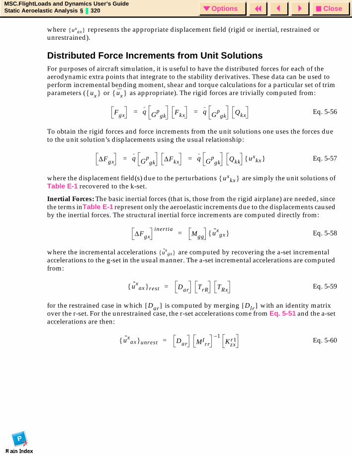
CloseOptionsMSC.FlightLoads and Dynamics User’s GuideStatic Aeroelastic Analysis § 320 Options
where represents the appropriate displacement field (rigid or inertial, restrained or unrestrained).
Distributed Force Increments from Unit SolutionsFor purposes of aircraft simulation, it is useful to have the distributed forces for each of the aerodynamic extra points that integrate to the stability derivatives. These data can be used to perform incremental bending moment, shear and torque calculations for a particular set of trim parameters ( or as appropriate). The rigid forces are trivially computed from:
Eq. 5-56
To obtain the rigid forces and force increments from the unit solutions one uses the forces due to the unit solution’s displacements using the usual relationship:
Eq. 5-57
where the displacement field(s) due to the perturbations are simply the unit solutions of Table E-1 recovered to the k-set.
Inertial Forces: The basic inertial forces (that is, those from the rigid airplane) are needed, since the terms inTable E-1 represent only the aeroelastic increments due to the displacements caused by the inertial forces. The structural inertial force increments are computed directly from:
Eq. 5-58
where the incremental accelerations are computed by recovering the a-set incremental accelerations to the g-set in the usual manner. The a-set incremental accelerations are computed from:
Eq. 5-59
for the restrained case in which is computed by merging with an identity matrix over the r-set. For the unrestrained case, the r-set accelerations come from Eq. 5-51 and the a-set accelerations are then:
Eq. 5-60
uxax
ux ux
Fgx q Gp
gkFkx q G
pgk
Qkx= =
∆Fgx q Gp
gk∆Fkx q G
pgk
Qkk uxkx = =
uxkx
∆Fgxinert ia
Mgg u··x
gx =
u··x
gx
u··x
ax rest Dar TrR TRx=
Dar[ ] Dlr[ ]
u··x
ax unrest Dar MIrr
1–Kzx
r1=
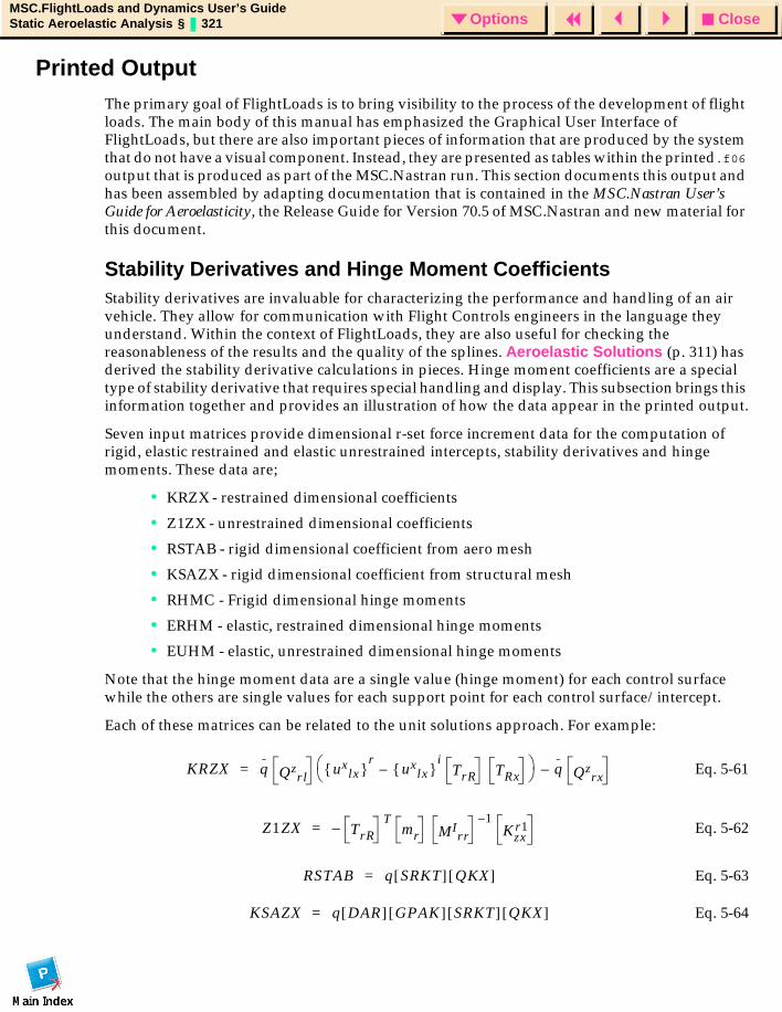
CloseOptionsMSC.FlightLoads and Dynamics User’s GuideStatic Aeroelastic Analysis § 321 Options
Printed OutputThe primary goal of FlightLoads is to bring visibility to the process of the development of flight loads. The main body of this manual has emphasized the Graphical User Interface of FlightLoads, but there are also important pieces of information that are produced by the system that do not have a visual component. Instead, they are presented as tables within the printed.f06 output that is produced as part of the MSC.Nastran run. This section documents this output and has been assembled by adapting documentation that is contained in the MSC.Nastran User’s Guide for Aeroelasticity, the Release Guide for Version 70.5 of MSC.Nastran and new material for this document.
Stability Derivatives and Hinge Moment Coefficients Stability derivatives are invaluable for characterizing the performance and handling of an air vehicle. They allow for communication with Flight Controls engineers in the language they understand. Within the context of FlightLoads, they are also useful for checking the reasonableness of the results and the quality of the splines. Aeroelastic Solutions (p. 311) has derived the stability derivative calculations in pieces. Hinge moment coefficients are a special type of stability derivative that requires special handling and display. This subsection brings this information together and provides an illustration of how the data appear in the printed output.
Seven input matrices provide dimensional r-set force increment data for the computation of rigid, elastic restrained and elastic unrestrained intercepts, stability derivatives and hinge moments. These data are;
• KRZX - restrained dimensional coefficients
• Z1ZX - unrestrained dimensional coefficients
• RSTAB - rigid dimensional coefficient from aero mesh
• KSAZX - rigid dimensional coefficient from structural mesh
• RHMC - Frigid dimensional hinge moments
• ERHM - elastic, restrained dimensional hinge moments
• EUHM - elastic, unrestrained dimensional hinge moments
Note that the hinge moment data are a single value (hinge moment) for each control surface while the others are single values for each support point for each control surface/intercept.
Each of these matrices can be related to the unit solutions approach. For example:
Eq. 5-61
Eq. 5-62
Eq. 5-63
Eq. 5-64
KRZX q Qzrl
uxlx
rux
lx i
TrR TRx– q Qz
rx–=
Z1ZX TrR–T
mr MIrr
1–Kzx
r1=
RSTAB q SRKT[ ] QKX[ ]=
KSAZX q DAR[ ] GPAK[ ] SRKT[ ] QKX[ ]=
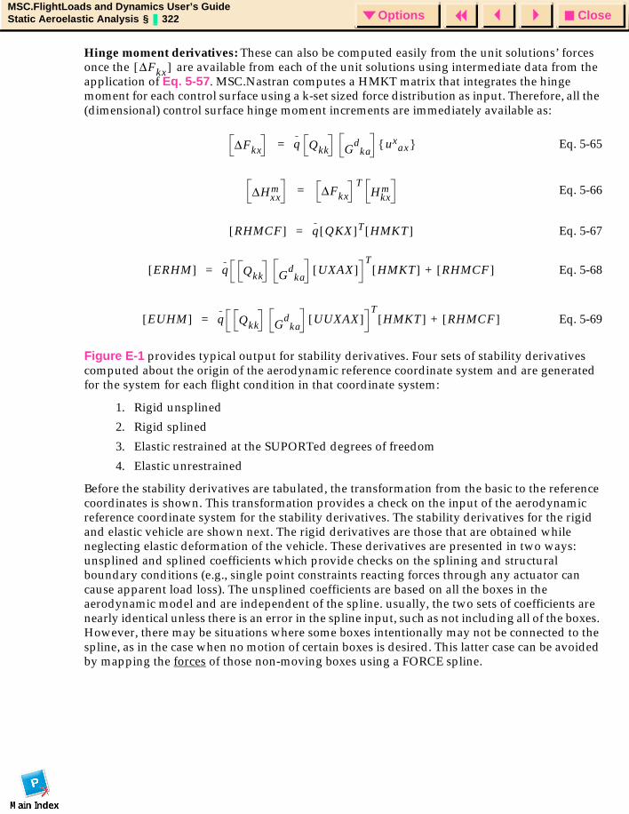
CloseOptionsMSC.FlightLoads and Dynamics User’s GuideStatic Aeroelastic Analysis § 322 Options
Hinge moment derivatives: These can also be computed easily from the unit solutions’ forces once the are available from each of the unit solutions using intermediate data from the application of Eq. 5-57. MSC.Nastran computes a HMKT matrix that integrates the hinge moment for each control surface using a k-set sized force distribution as input. Therefore, all the (dimensional) control surface hinge moment increments are immediately available as:
Eq. 5-65
Eq. 5-66
Eq. 5-67
Eq. 5-68
Eq. 5-69
Figure E-1 provides typical output for stability derivatives. Four sets of stability derivatives computed about the origin of the aerodynamic reference coordinate system and are generated for the system for each flight condition in that coordinate system:
1. Rigid unsplined
2. Rigid splined
3. Elastic restrained at the SUPORTed degrees of freedom
4. Elastic unrestrained
Before the stability derivatives are tabulated, the transformation from the basic to the reference coordinates is shown. This transformation provides a check on the input of the aerodynamic reference coordinate system for the stability derivatives. The stability derivatives for the rigid and elastic vehicle are shown next. The rigid derivatives are those that are obtained while neglecting elastic deformation of the vehicle. These derivatives are presented in two ways: unsplined and splined coefficients which provide checks on the splining and structural boundary conditions (e.g., single point constraints reacting forces through any actuator can cause apparent load loss). The unsplined coefficients are based on all the boxes in the aerodynamic model and are independent of the spline. usually, the two sets of coefficients are nearly identical unless there is an error in the spline input, such as not including all of the boxes. However, there may be situations where some boxes intentionally may not be connected to the spline, as in the case when no motion of certain boxes is desired. This latter case can be avoided by mapping the forces of those non-moving boxes using a FORCE spline.
∆Fkx[ ]
∆Fkx q Qkk Gd
kaux
ax =
∆Hxxm ∆Fkx
THkx
m=
RHMCF[ ] q QKX[ ]T HMKT[ ]=
ERHM[ ] q Qkk Gd
kaUXAX[ ]
THMKT[ ] RHMCF[ ]+=
EUHM[ ] q Qkk Gd
kaUUXAX[ ]
THMKT[ ] RHMCF[ ]+=
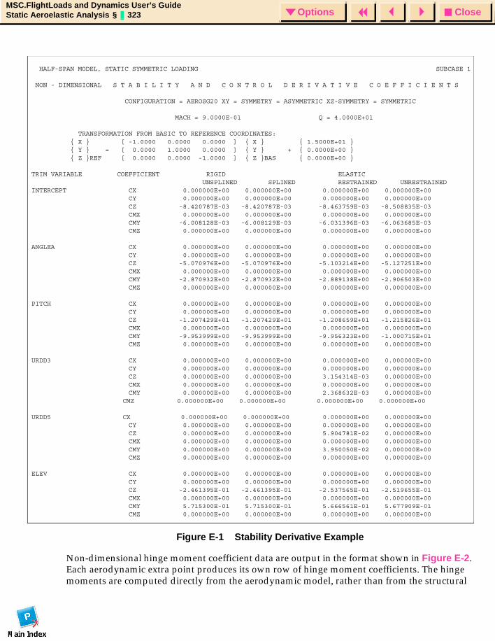
CloseOptionsMSC.FlightLoads and Dynamics User’s GuideStatic Aeroelastic Analysis § 323 Options
Figure E-1 Stability Derivative Example
Non-dimensional hinge moment coefficient data are output in the format shown in Figure E-2. Each aerodynamic extra point produces its own row of hinge moment coefficients. The hinge moments are computed directly from the aerodynamic model, rather than from the structural
HALF-SPAN MODEL, STATIC SYMMETRIC LOADING SUBCASE 1
NON - DIMENSIONAL S T A B I L I T Y A N D C O N T R O L D E R I V A T I V E C O E F F I C I E N T S
CONFIGURATION = AEROSG20 XY = SYMMETRY = ASYMMETRIC XZ-SYMMETRY = SYMMETRIC
MACH = 9.0000E-01 Q = 4.0000E+01
TRANSFORMATION FROM BASIC TO REFERENCE COORDINATES: X [ -1.0000 0.0000 0.0000 ] X 1.5000E+01 Y = [ 0.0000 1.0000 0.0000 ] Y + 0.0000E+00 Z REF [ 0.0000 0.0000 -1.0000 ] Z BAS 0.0000E+00
TRIM VARIABLE COEFFICIENT RIGID ELASTIC UNSPLINED SPLINED RESTRAINED UNRESTRAINEDINTERCEPT CX 0.000000E+00 0.000000E+00 0.000000E+00 0.000000E+00 CY 0.000000E+00 0.000000E+00 0.000000E+00 0.000000E+00 CZ -8.420787E-03 -8.420787E-03 -8.463759E-03 -8.508835E-03 CMX 0.000000E+00 0.000000E+00 0.000000E+00 0.000000E+00 CMY -6.008128E-03 -6.008129E-03 -6.031396E-03 -6.063685E-03 CMZ 0.000000E+00 0.000000E+00 0.000000E+00 0.000000E+00
ANGLEA CX 0.000000E+00 0.000000E+00 0.000000E+00 0.000000E+00 CY 0.000000E+00 0.000000E+00 0.000000E+00 0.000000E+00 CZ -5.070976E+00 -5.070976E+00 -5.103214E+00 -5.127251E+00 CMX 0.000000E+00 0.000000E+00 0.000000E+00 0.000000E+00 CMY -2.870932E+00 -2.870932E+00 -2.889138E+00 -2.906503E+00 CMZ 0.000000E+00 0.000000E+00 0.000000E+00 0.000000E+00
PITCH CX 0.000000E+00 0.000000E+00 0.000000E+00 0.000000E+00 CY 0.000000E+00 0.000000E+00 0.000000E+00 0.000000E+00 CZ -1.207429E+01 -1.207429E+01 -1.208659E+01 -1.215826E+01 CMX 0.000000E+00 0.000000E+00 0.000000E+00 0.000000E+00 CMY -9.953999E+00 -9.953999E+00 -9.956323E+00 -1.000715E+01 CMZ 0.000000E+00 0.000000E+00 0.000000E+00 0.000000E+00
URDD3 CX 0.000000E+00 0.000000E+00 0.000000E+00 0.000000E+00 CY 0.000000E+00 0.000000E+00 0.000000E+00 0.000000E+00 CZ 0.000000E+00 0.000000E+00 3.154314E-03 0.000000E+00 CMX 0.000000E+00 0.000000E+00 0.000000E+00 0.000000E+00 CMY 0.000000E+00 0.000000E+00 2.368632E-03 0.000000E+00
CMZ 0.000000E+00 0.000000E+00 0.000000E+00 0.000000E+00
URDD5 CX 0.000000E+00 0.000000E+00 0.000000E+00 0.000000E+00 CY 0.000000E+00 0.000000E+00 0.000000E+00 0.000000E+00 CZ 0.000000E+00 0.000000E+00 5.904781E-02 0.000000E+00 CMX 0.000000E+00 0.000000E+00 0.000000E+00 0.000000E+00 CMY 0.000000E+00 0.000000E+00 3.950050E-02 0.000000E+00 CMZ 0.000000E+00 0.000000E+00 0.000000E+00 0.000000E+00
ELEV CX 0.000000E+00 0.000000E+00 0.000000E+00 0.000000E+00 CY 0.000000E+00 0.000000E+00 0.000000E+00 0.000000E+00 CZ -2.461395E-01 -2.461395E-01 -2.537565E-01 -2.519655E-01 CMX 0.000000E+00 0.000000E+00 0.000000E+00 0.000000E+00 CMY 5.715300E-01 5.715300E-01 5.666561E-01 5.677909E-01 CMZ 0.000000E+00 0.000000E+00 0.000000E+00 0.000000E+00
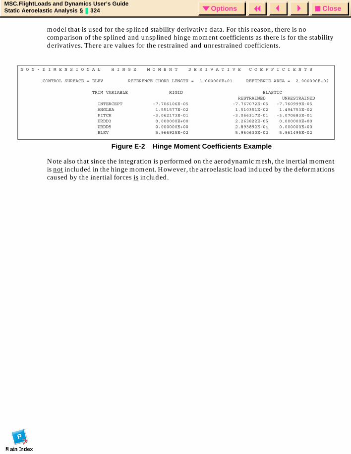
CloseOptionsMSC.FlightLoads and Dynamics User’s GuideStatic Aeroelastic Analysis § 324 Options
model that is used for the splined stability derivative data. For this reason, there is no comparison of the splined and unsplined hinge moment coefficients as there is for the stability derivatives. There are values for the restrained and unrestrained coefficients.
Figure E-2 Hinge Moment Coefficients Example
Note also that since the integration is performed on the aerodynamic mesh, the inertial moment is not included in the hinge moment. However, the aeroelastic load induced by the deformations caused by the inertial forces is included.
N O N - D I M E N S I O N A L H I N G E M O M E N T D E R I V A T I V E C O E F F I C I E N T S
CONTROL SURFACE = ELEV REFERENCE CHORD LENGTH = 1.000000E+01 REFERENCE AREA = 2.000000E+02
TRIM VARIABLE RIGID ELASTIC RESTRAINED UNRESTRAINED INTERCEPT -7.706106E-05 -7.767072E-05 -7.760999E-05 ANGLEA 1.551577E-02 1.510351E-02 1.494753E-02 PITCH -3.062173E-01 -3.066317E-01 -3.070683E-01 URDD3 0.000000E+00 2.263822E-05 0.000000E+00 URDD5 0.000000E+00 2.893892E-04 0.000000E+00 ELEV 5.966925E-02 5.960630E-02 5.961495E-02
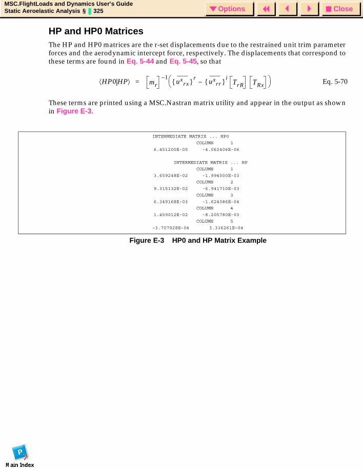
CloseOptionsMSC.FlightLoads and Dynamics User’s GuideStatic Aeroelastic Analysis § 325 Options
HP and HP0 MatricesThe HP and HP0 matrices are the r-set displacements due to the restrained unit trim parameter forces and the aerodynamic intercept force, respectively. The displacements that correspond to these terms are found in Eq. 5-44 and Eq. 5-45, so that
Eq. 5-70
These terms are printed using a MSC.Nastran matrix utility and appear in the output as shown in Figure E-3.
Figure E-3 HP0 and HP Matrix Example
HP0 HP⟨ | ⟩ mr1–
uxrx r
uxrr i
TrR TRx– =
INTERMEDIATE MATRIX ... HP0
COLUMN 1
6.451200E-05 -4.062406E-06
INTERMEDIATE MATRIX ... HP
COLUMN 1
3.659248E-02 -1.994000E-03
COLUMN 2
9.315132E-02 -6.941710E-03
COLUMN 3
6.349168E-03 -1.624086E-04
COLUMN 4
1.459012E-02 -8.205780E-03
COLUMN 5
-3.707928E-04 3.336261E-04
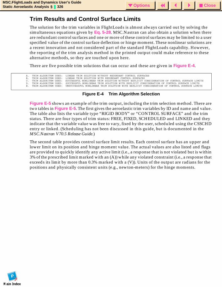
CloseOptionsMSC.FlightLoads and Dynamics User’s GuideStatic Aeroelastic Analysis § 326 Options
Trim Results and Control Surface LimitsThe solution for the trim variables in FlightLoads is almost always carried out by solving the simultaneous equations given by Eq. 5-28. MSC.Nastran can also obtain a solution when there are redundant control surfaces and one or more of these control surfaces may be limited to a user specified value of the control surface deflection or hinge moment. These nonlinear solutions are a recent innovation and not considered part of the standard FlightLoads capability. However, the reporting of the trim analysis method in the printed output could make reference to these alternative methods, so they are touched upon here.
There are five possible trim solutions that can occur and these are given in Figure E-4.
Figure E-4 Trim Algorithm Selection
Figure E-5 shows an example of the trim output, including the trim selection method. There are two tables in Figure E-5. The first gives the aeroelastic trim variables by ID and name and value. The table also lists the variable type “RIGID BODY” or “CONTROL SURFACE” and the trim status. There are four types of trim status: FREE, FIXED, SCHEDULED and LINKED and they indicate that the variable value was free to vary, fixed by the user, scheduled using the CSSCHD entry or linked. (Scheduling has not been discussed in this guide, but is documented in the MSC.Nastran V70.5 Release Guide.)
The second table provides control surface limit results. Each control surface has an upper and lower limit on its position and hinge moment value. The actual values are also listed and flags are provided to quickly identify any active limit (i.e., a response that is not violated but is within 3% of the prescribed limit marked with an (A)) while any violated constraint (i.e., a response that exceeds its limit by more than 0.3% marked with a (V)). Units of the output are radians for the positions and physically consistent units (e.g., newton-meters) for the hinge moments.
A. TRIM ALGORITHM USED: LINEAR TRIM SOLUTION WITHOUT REDUNDANT CONTROL SURFACESB. TRIM ALGORITHM USED: LINEAR TRIM SOLUTION WITH REDUNDANT CONTROL SURFACESC. TRIM ALGORITHM USED: SUCCESSFUL NONLINEAR TRIM SOLUTION WITHOUT EXPLICIT CONSIDERATION OF CONTROL SURFACE LIMITSD. TRIM ALGORITHM USED: SUCCESSFUL NONLINEAR TRIM SOLUTION WITH EXPLICIT CONSIDERATION OF CONTROL SURFACE LIMITSE. TRIM ALGORITHM USED: UNSUCCESSFUL NONLINEAR TRIM SOLUTION WITH EXPLICIT CONSIDERATION OF CONTROL SURFACE LIMITS
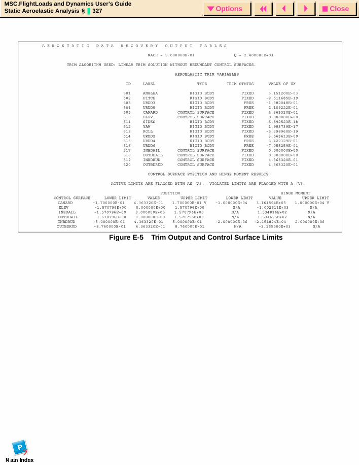
CloseOptionsMSC.FlightLoads and Dynamics User’s GuideStatic Aeroelastic Analysis § 327 Options
Figure E-5 Trim Output and Control Surface Limits
A E R O S T A T I C D A T A R E C O V E R Y O U T P U T T A B L E S
MACH = 9.000000E-01 Q = 2.400000E+03
TRIM ALGORITHM USED: LINEAR TRIM SOLUTION WITHOUT REDUNDANT CONTROL SURFACES.
AEROELASTIC TRIM VARIABLES
ID LABEL TYPE TRIM STATUS VALUE OF UX
501 ANGLEA RIGID BODY FIXED 3.151200E-03 502 PITCH RIGID BODY FIXED -2.511685E-19 503 URDD3 RIGID BODY FREE -1.382048E+01 504 URDD5 RIGID BODY FREE 2.109222E-01 505 CANARD CONTROL SURFACE FIXED 4.363320E-01 510 ELEV CONTROL SURFACE FIXED 0.000000E+00 511 SIDES RIGID BODY FIXED -5.592523E-18 512 YAW RIGID BODY FIXED 1.983739E-17 513 ROLL RIGID BODY FIXED -6.398960E-19 514 URDD2 RIGID BODY FREE 3.563613E+00 515 URDD4 RIGID BODY FREE 5.422129E-01 516 URDD6 RIGID BODY FREE -7.055259E-01 517 INBDAIL CONTROL SURFACE FIXED 0.000000E+00 518 OUTBDAIL CONTROL SURFACE FIXED 0.000000E+00 519 INBDRUD CONTROL SURFACE FIXED 4.363320E-01 520 OUTBDRUD CONTROL SURFACE FIXED 4.363320E-01
CONTROL SURFACE POSITION AND HINGE MOMENT RESULTS
ACTIVE LIMITS ARE FLAGGED WITH AN (A), VIOLATED LIMITS ARE FLAGGED WITH A (V).
POSITION HINGE MOMENT CONTROL SURFACE LOWER LIMIT VALUE UPPER LIMIT LOWER LIMIT VALUE UPPER LIMIT CANARD -1.700000E-01 4.363320E-01 1.700000E-01 V -1.000000E+04 3.161594E+05 1.000000E+04 V ELEV -1.570796E+00 0.000000E+00 1.570796E+00 N/A -1.002511E+03 N/A INBDAIL -1.570796E+00 0.000000E+00 1.570796E+00 N/A 1.534836E+02 N/A OUTBDAIL -1.570796E+00 0.000000E+00 1.570796E+00 N/A 1.534625E+02 N/A INBDRUD -5.000000E-01 4.363320E-01 5.000000E-01 -2.000000E+06 -2.151824E+04 2.000000E+06 OUTBDRUD -8.760000E-01 4.363320E-01 8.760000E-01 N/A -2.165500E+03 N/A
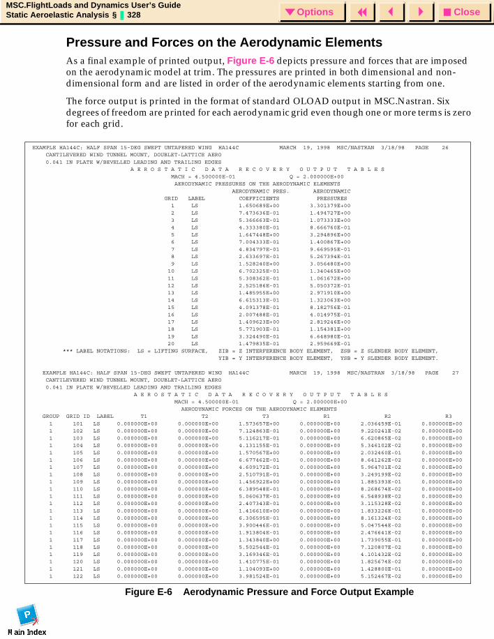
CloseOptionsMSC.FlightLoads and Dynamics User’s GuideStatic Aeroelastic Analysis § 328 Options
Pressure and Forces on the Aerodynamic ElementsAs a final example of printed output, Figure E-6 depicts pressure and forces that are imposed on the aerodynamic model at trim. The pressures are printed in both dimensional and non-dimensional form and are listed in order of the aerodynamic elements starting from one.
The force output is printed in the format of standard OLOAD output in MSC.Nastran. Six degrees of freedom are printed for each aerodynamic grid even though one or more terms is zero for each grid.
Figure E-6 Aerodynamic Pressure and Force Output Example
EXAMPLE HA144C: HALF SPAN 15-DEG SWEPT UNTAPERED WING HA144C MARCH 19, 1998 MSC/NASTRAN 3/18/98 PAGE 26 CANTILEVERED WIND TUNNEL MOUNT, DOUBLET-LATTICE AERO
0.041 IN PLATE W/BEVELLED LEADING AND TRAILING EDGES A E R O S T A T I C D A T A R E C O V E R Y O U T P U T T A B L E S MACH = 4.500000E-01 Q = 2.000000E+00 AERODYNAMIC PRESSURES ON THE AERODYNAMIC ELEMENTS
AERODYNAMIC PRES. AERODYNAMIC GRID LABEL COEFFICIENTS PRESSURES 1 LS 1.650689E+00 3.301379E+00 2 LS 7.473636E-01 1.494727E+00
3 LS 5.366663E-01 1.073333E+00 4 LS 4.333380E-01 8.666760E-01 5 LS 1.647448E+00 3.294896E+00 6 LS 7.004333E-01 1.400867E+00
7 LS 4.834797E-01 9.669595E-01 8 LS 2.633697E-01 5.267394E-01 9 LS 1.528240E+00 3.056480E+00 10 LS 6.702325E-01 1.340465E+00
11 LS 5.308362E-01 1.061672E+00 12 LS 2.525186E-01 5.050372E-01 13 LS 1.485955E+00 2.971910E+00 14 LS 6.615313E-01 1.323063E+00
15 LS 4.091378E-01 8.182756E-01 16 LS 2.007488E-01 4.014975E-01 17 LS 1.409623E+00 2.819246E+00 18 LS 5.771903E-01 1.154381E+00
19 LS 3.324490E-01 6.648980E-01 20 LS 1.479835E-01 2.959669E-01 *** LABEL NOTATIONS: LS = LIFTING SURFACE, ZIB = Z INTERFERENCE BODY ELEMENT, ZSB = Z SLENDER BODY ELEMENT, YIB = Y INTERFERENCE BODY ELEMENT, YSB = Y SLENDER BODY ELEMENT.
EXAMPLE HA144C: HALF SPAN 15-DEG SWEPT UNTAPERED WING HA144C MARCH 19, 1998 MSC/NASTRAN 3/18/98 PAGE 27 CANTILEVERED WIND TUNNEL MOUNT, DOUBLET-LATTICE AERO 0.041 IN PLATE W/BEVELLED LEADING AND TRAILING EDGES
A E R O S T A T I C D A T A R E C O V E R Y O U T P U T T A B L E S MACH = 4.500000E-01 Q = 2.000000E+00 AERODYNAMIC FORCES ON THE AERODYNAMIC ELEMENTS GROUP GRID ID LABEL T1 T2 T3 R1 R2 R3
1 101 LS 0.000000E+00 0.000000E+00 1.573657E+00 0.000000E+00 2.036459E-01 0.000000E+00 1 102 LS 0.000000E+00 0.000000E+00 7.124863E-01 0.000000E+00 9.220241E-02 0.000000E+00 1 103 LS 0.000000E+00 0.000000E+00 5.116217E-01 0.000000E+00 6.620865E-02 0.000000E+00 1 104 LS 0.000000E+00 0.000000E+00 4.131155E-01 0.000000E+00 5.346102E-02 0.000000E+00
1 105 LS 0.000000E+00 0.000000E+00 1.570567E+00 0.000000E+00 2.032460E-01 0.000000E+00 1 106 LS 0.000000E+00 0.000000E+00 6.677462E-01 0.000000E+00 8.641262E-02 0.000000E+00 1 107 LS 0.000000E+00 0.000000E+00 4.609172E-01 0.000000E+00 5.964701E-02 0.000000E+00 1 108 LS 0.000000E+00 0.000000E+00 2.510791E-01 0.000000E+00 3.249199E-02 0.000000E+00
1 109 LS 0.000000E+00 0.000000E+00 1.456922E+00 0.000000E+00 1.885393E-01 0.000000E+00 1 110 LS 0.000000E+00 0.000000E+00 6.389548E-01 0.000000E+00 8.268674E-02 0.000000E+00 1 111 LS 0.000000E+00 0.000000E+00 5.060637E-01 0.000000E+00 6.548938E-02 0.000000E+00 1 112 LS 0.000000E+00 0.000000E+00 2.407343E-01 0.000000E+00 3.115328E-02 0.000000E+00
1 113 LS 0.000000E+00 0.000000E+00 1.416610E+00 0.000000E+00 1.833226E-01 0.000000E+00 1 114 LS 0.000000E+00 0.000000E+00 6.306595E-01 0.000000E+00 8.161324E-02 0.000000E+00 1 115 LS 0.000000E+00 0.000000E+00 3.900446E-01 0.000000E+00 5.047544E-02 0.000000E+00 1 116 LS 0.000000E+00 0.000000E+00 1.913804E-01 0.000000E+00 2.476641E-02 0.000000E+00
1 117 LS 0.000000E+00 0.000000E+00 1.343840E+00 0.000000E+00 1.739055E-01 0.000000E+00 1 118 LS 0.000000E+00 0.000000E+00 5.502544E-01 0.000000E+00 7.120807E-02 0.000000E+00 1 119 LS 0.000000E+00 0.000000E+00 3.169346E-01 0.000000E+00 4.101432E-02 0.000000E+00 1 120 LS 0.000000E+00 0.000000E+00 1.410775E-01 0.000000E+00 1.825674E-02 0.000000E+00
1 121 LS 0.000000E+00 0.000000E+00 1.104093E+00 0.000000E+00 1.428800E-01 0.000000E+00 1 122 LS 0.000000E+00 0.000000E+00 3.981524E-01 0.000000E+00 5.152467E-02 0.000000E+00
CloseOptionsMSC.FlightLoads and Dynamics User’s GuideAero Mesh Interface File Format § 329 Options
MSC.FlightLoads and Dynamics User’s Guide7f
APPENDIX
F Aero Mesh Interface File Format
Introduction
Definition of an Aerodynamic Mesh Interface File (AMIF)
AMIF Format and Reading
Sample AMI File

CloseOptionsMSC.FlightLoads and Dynamics User’s GuideAero Mesh Interface File Format § 330 Options
IntroductionThis appendix describes the format of the various entries that make up the Aerodynamic Mesh Interface File (AMIF). This file format allows external meshes to be imported as MSC.FLD “3D” aerodynamic meshes. These meshes can then be used to define other aerodynamic data such as Splines, Nonlinear Parametric Loads, Monitor Points, and Control Devices.

CloseOptionsMSC.FlightLoads and Dynamics User’s GuideAero Mesh Interface File Format § 331 Options
Definition of an Aerodynamic Mesh Interface File (AMIF)To use “external” aerodynamic codes within MSC.FlightLoads and Dynamics the aerodynamic mesh has to be known. The mesh is needed for different purposes:
1. Mesh geometry has to be known to do any aeroelastic analysis.
2. Mesh geometry is needed for splining.
3. Mesh geometry (external node and element IDs) is used to display results and verify the splines.
To serve all these needs, a simple interface file has been defined. There is a minimum set of information needed to do most of this:
1. Aerodynamic grid points
2. Aerodynamic panels (boxes, elements, or whatever you want to call them)
This minimum set of information will be sufficient to make the aerodynamic mesh known to MSC.FlightLoads and Dynamics and is sufficient to do interactive splining and spline verification in MSC.FLD. The following tables describe all entries of an AMIF designed to do all functions described above.
General Rules1. All fields are separated by one or more spaces (not tabs).
2. The entry name must be upper case and must start in the first column.
3. The order is not important.
Entry: Comment
Comment line which will be ignored by the AMIF reader.
Example:
# This file was created by the XYZ Euler Code.
Format:
1 2 3 4 5 6 7 8
#
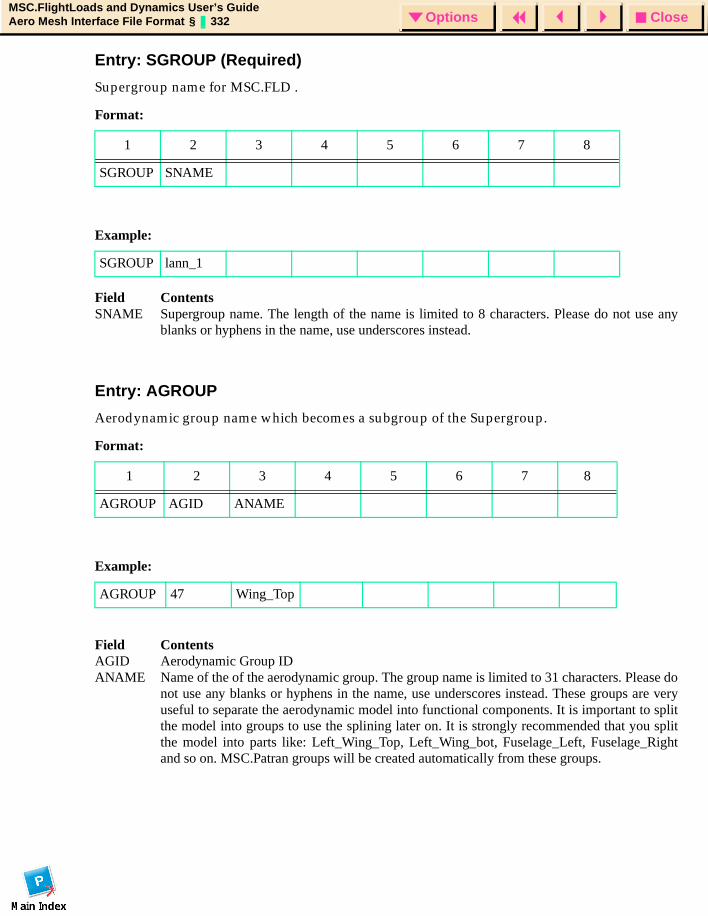
CloseOptionsMSC.FlightLoads and Dynamics User’s GuideAero Mesh Interface File Format § 332 Options
Entry: SGROUP (Required)
Supergroup name for MSC.FLD .
Field ContentsSNAME Supergroup name. The length of the name is limited to 8 characters. Please do not use any
blanks or hyphens in the name, use underscores instead.
Entry: AGROUP
Aerodynamic group name which becomes a subgroup of the Supergroup.
Field ContentsAGID Aerodynamic Group IDANAME Name of the of the aerodynamic group. The group name is limited to 31 characters. Please do
not use any blanks or hyphens in the name, use underscores instead. These groups are veryuseful to separate the aerodynamic model into functional components. It is important to splitthe model into groups to use the splining later on. It is strongly recommended that you splitthe model into parts like: Left_Wing_Top, Left_Wing_bot, Fuselage_Left, Fuselage_Rightand so on. MSC.Patran groups will be created automatically from these groups.
Format:
1 2 3 4 5 6 7 8
SGROUP SNAME
Example:
SGROUP lann_1
Format:
1 2 3 4 5 6 7 8
AGROUP AGID ANAME
Example:
AGROUP 47 Wing_Top
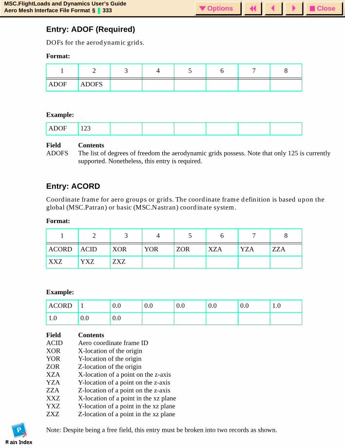
CloseOptionsMSC.FlightLoads and Dynamics User’s GuideAero Mesh Interface File Format § 333 Options
Entry: ADOF (Required)
DOFs for the aerodynamic grids.
Field ContentsADOFS The list of degrees of freedom the aerodynamic grids possess. Note that only 125 is currently
supported. Nonetheless, this entry is required.
Entry: ACORD
Coordinate frame for aero groups or grids. The coordinate frame definition is based upon the global (MSC.Patran) or basic (MSC.Nastran) coordinate system.
Field ContentsACID Aero coordinate frame IDXOR X-location of the originYOR Y-location of the originZOR Z-location of the originXZA X-location of a point on the z-axisYZA Y-location of a point on the z-axisZZA Z-location of a point on the z-axisXXZ X-location of a point in the xz planeYXZ Y-location of a point in the xz planeZXZ Z-location of a point in the xz plane
Note: Despite being a free field, this entry must be broken into two records as shown.
Format:
1 2 3 4 5 6 7 8
ADOF ADOFS
Example:
ADOF 123
Format:
1 2 3 4 5 6 7 8
ACORD ACID XOR YOR ZOR XZA YZA ZZA
XXZ YXZ ZXZ
Example:
ACORD 1 0.0 0.0 0.0 0.0 0.0 1.0
1.0 0.0 0.0
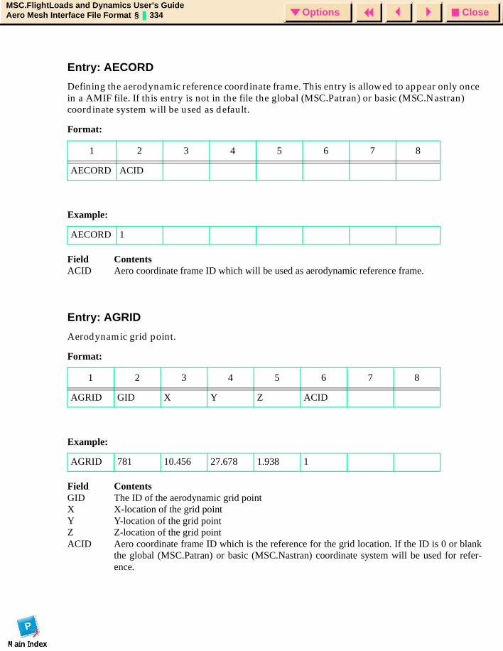
CloseOptionsMSC.FlightLoads and Dynamics User’s GuideAero Mesh Interface File Format § 334 Options
Entry: AECORD
Defining the aerodynamic reference coordinate frame. This entry is allowed to appear only once in a AMIF file. If this entry is not in the file the global (MSC.Patran) or basic (MSC.Nastran) coordinate system will be used as default.
Field ContentsACID Aero coordinate frame ID which will be used as aerodynamic reference frame.
Entry: AGRID
Aerodynamic grid point.
Field ContentsGID The ID of the aerodynamic grid pointX X-location of the grid pointY Y-location of the grid pointZ Z-location of the grid pointACID Aero coordinate frame ID which is the reference for the grid location. If the ID is 0 or blank
the global (MSC.Patran) or basic (MSC.Nastran) coordinate system will be used for refer-ence.
Format:
1 2 3 4 5 6 7 8
AECORD ACID
Example:
AECORD 1
Format:
1 2 3 4 5 6 7 8
AGRID GID X Y Z ACID
Example:
AGRID 781 10.456 27.678 1.938 1
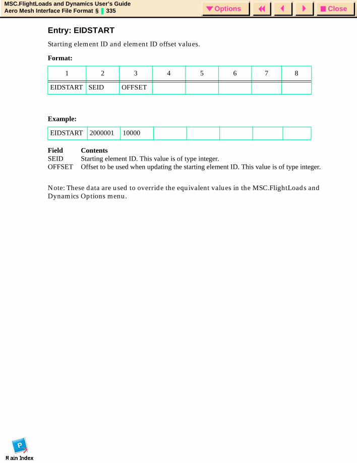
CloseOptionsMSC.FlightLoads and Dynamics User’s GuideAero Mesh Interface File Format § 335 Options
Entry: EIDSTART
Starting element ID and element ID offset values.
Field ContentsSEID Starting element ID. This value is of type integer.OFFSET Offset to be used when updating the starting element ID. This value is of type integer.
Note: These data are used to override the equivalent values in the MSC.FlightLoads and Dynamics Options menu.
Format:
1 2 3 4 5 6 7 8
EIDSTART SEID OFFSET
Example:
EIDSTART 2000001 10000
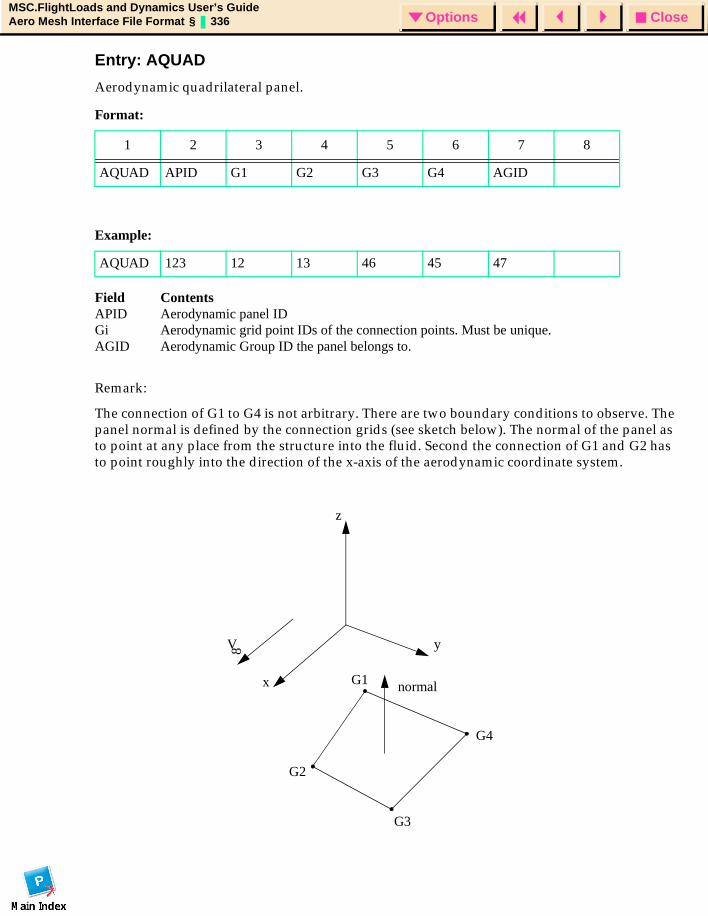
CloseOptionsMSC.FlightLoads and Dynamics User’s GuideAero Mesh Interface File Format § 336 Options
Entry: AQUAD
Aerodynamic quadrilateral panel.
Field ContentsAPID Aerodynamic panel IDGi Aerodynamic grid point IDs of the connection points. Must be unique.AGID Aerodynamic Group ID the panel belongs to.
Remark:
The connection of G1 to G4 is not arbitrary. There are two boundary conditions to observe. The panel normal is defined by the connection grids (see sketch below). The normal of the panel as to point at any place from the structure into the fluid. Second the connection of G1 and G2 has to point roughly into the direction of the x-axis of the aerodynamic coordinate system.
Format:
1 2 3 4 5 6 7 8
AQUAD APID G1 G2 G3 G4 AGID
Example:
AQUAD 123 12 13 46 45 47
x
y
z
V 8
normalG1
G2
G3
G4
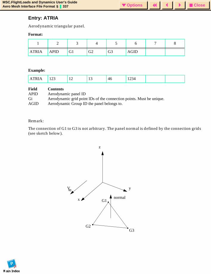
CloseOptionsMSC.FlightLoads and Dynamics User’s GuideAero Mesh Interface File Format § 337 Options
Entry: ATRIA
Aerodynamic triangular panel.
Field ContentsAPID Aerodynamic panel IDGi Aerodynamic grid point IDs of the connection points. Must be unique.AGID Aerodynamic Group ID the panel belongs to.
Remark:
The connection of G1 to G3 is not arbitrary. The panel normal is defined by the connection grids (see sketch below).
Format:
1 2 3 4 5 6 7 8
ATRIA APID G1 G2 G3 AGID
Example:
ATRIA 123 12 13 46 1234
x
y
z
V 8
normalG1
G2G3

CloseOptionsMSC.FlightLoads and Dynamics User’s GuideAero Mesh Interface File Format § 338 Options
AMIF Format and ReadingThe AMIF does not use a fixed format but keep in mind that all numbers will be stored in single precision. That is equivalent to I10 for IDs and 6-8 significant places for real numbers. The appearance of the fields is arbitrary. The standard extension of the AMIF is ami e.g. lann_1.ami.
When reading the AMIF into MSC.FLD the grids and panels may be renumbered since MSC.Patran requires unique grid and element IDs. While reading the file the aerodynamic super group will be created and within it the component groups will be created. All panels will be stored into their component group. The aerodynamic grids will be gathered accordingly into the groups. Finally, an attempt will be made to create an underlying surface from the elements/nodes of each group. If the attempt fails, you will receive a warning message that allows you to continue or terminate the import. If you continue, then the only effect will be that the group will NOT have an underlying surface associated with the region. This lack should have little or no impact. However, if you desire surfaces, you may wish to continue and double check the elements. Failure may indicate too warped a surface -- it maybe that, by breaking the group into pieces you can obtain a surface.
Element and Node Numbering - The following rules will be applied to your AMIF.
• If the lowest ID of any AGRID is greater than the largest grid ID in the MSC.Patran database, the AMIF numbers will be retained. Otherwise, they will be offset.
• Element numbers are ALWAYS reassigned. However, the MSC.FLD Options menu element numbering rules will be applied (contiguous IDs in the group with an integer multiple of the increment to determine the next groups stacking ID). An EIDSTART entry will override the options.
Hint:
While importing the aero grid locations the absolute value of the location components are important. The components are checked against the Global Tolerance. If a component is smaller than the Global Tolerance it is not created. So please make sure the Global Tolerance used is correct for the size of your model.
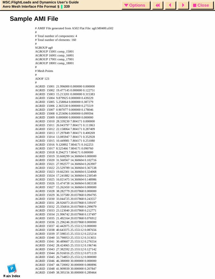
CloseOptionsMSC.FlightLoads and Dynamics User’s GuideAero Mesh Interface File Format § 339 Options
Sample AMI File# AMIF File generated from A502 Flat File: ag0.M0400.a502## Total number of components: 4# Total number of elements: 160#SGROUP ag0 AGROUP 15001 comp_15001AGROUP 16001 comp_16001AGROUP 17001 comp_17001AGROUP 18001 comp_18001## Mesh Points#ADOF 123#AGRID 15001 21.996000 0.000000 0.000000 AGRID 15002 19.477145 0.000000 0.122751 AGRID 15003 15.213201 0.000000 0.315383 AGRID 15004 9.879925 0.000000 0.439229 AGRID 15005 5.258064 0.000000 0.387279 AGRID 15006 2.365530 0.000000 0.275519 AGRID 15007 0.907077 0.000000 0.178046 AGRID 15008 0.253696 0.000000 0.099594 AGRID 15009 0.000000 0.000000 0.000000 AGRID 15010 28.339230 7.804171 0.000000 AGRID 15011 26.043797 7.804171 0.111863 AGRID 15012 22.158064 7.804171 0.287409 AGRID 15013 17.297849 7.804171 0.400269 AGRID 15014 13.085947 7.804171 0.352928 AGRID 15015 10.449981 7.804171 0.251080 AGRID 15016 9.120892 7.804171 0.162253 AGRID 15017 8.525466 7.804171 0.090760 AGRID 15018 8.294273 7.804171 0.000000 AGRID 15019 33.668299 14.360604 0.000000 AGRID 15020 31.560567 14.360604 0.102716 AGRID 15021 27.992577 14.360604 0.263907 AGRID 15022 23.529789 14.360604 0.367538 AGRID 15023 19.662301 14.360604 0.324068 AGRID 15024 17.241882 14.360604 0.230549 AGRID 15025 16.021475 14.360604 0.148986 AGRID 15026 15.474738 14.360604 0.083338 AGRID 15027 15.262450 14.360604 0.000000 AGRID 15028 38.282779 20.037868 0.000000 AGRID 15029 36.337580 20.037868 0.094795 AGRID 15030 33.044725 20.037868 0.243557 AGRID 15031 28.926073 20.037868 0.339197 AGRID 15032 25.356816 20.037868 0.299079 AGRID 15033 23.123040 20.037868 0.212771 AGRID 15034 21.996742 20.037868 0.137497 AGRID 15035 21.492164 20.037868 0.076912 AGRID 15036 21.296246 20.037868 0.000000 AGRID 15037 42.442075 25.155112 0.000000 AGRID 15038 40.643375 25.155112 0.087656 AGRID 15039 37.598515 25.155112 0.225214 AGRID 15040 33.790053 25.155112 0.313651 AGRID 15041 30.489607 25.155112 0.276554 AGRID 15042 28.424065 25.155112 0.196746 AGRID 15043 27.382592 25.155112 0.127142 AGRID 15044 26.916016 25.155112 0.071119 AGRID 15045 26.734853 25.155112 0.000000 AGRID 15046 46.380000 30.000000 0.000000 AGRID 15047 44.720002 30.000000 0.080896 AGRID 15048 41.909939 30.000000 0.207847 AGRID 15049 38.395156 30.000000 0.289464
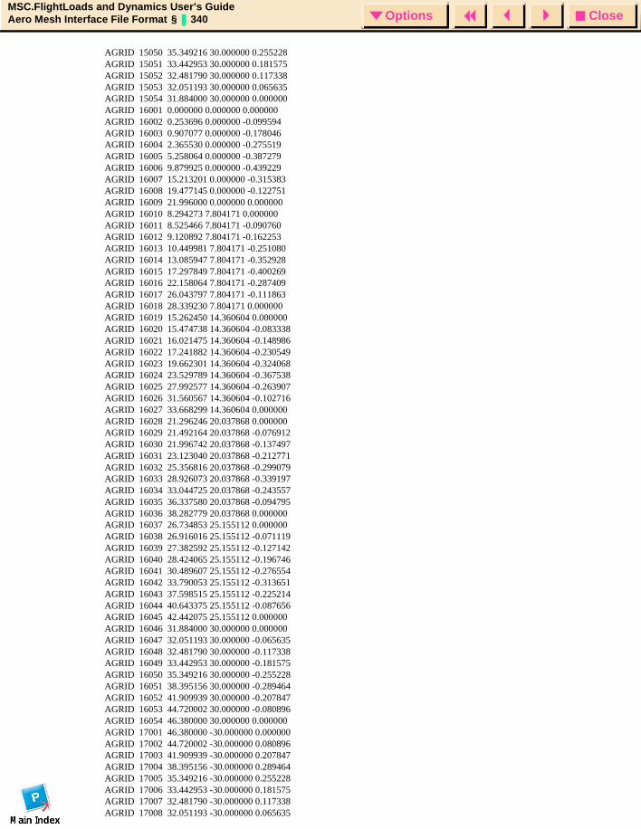
CloseOptionsMSC.FlightLoads and Dynamics User’s GuideAero Mesh Interface File Format § 340 Options
AGRID 15050 35.349216 30.000000 0.255228 AGRID 15051 33.442953 30.000000 0.181575 AGRID 15052 32.481790 30.000000 0.117338 AGRID 15053 32.051193 30.000000 0.065635 AGRID 15054 31.884000 30.000000 0.000000 AGRID 16001 0.000000 0.000000 0.000000 AGRID 16002 0.253696 0.000000 -0.099594 AGRID 16003 0.907077 0.000000 -0.178046 AGRID 16004 2.365530 0.000000 -0.275519 AGRID 16005 5.258064 0.000000 -0.387279 AGRID 16006 9.879925 0.000000 -0.439229 AGRID 16007 15.213201 0.000000 -0.315383 AGRID 16008 19.477145 0.000000 -0.122751 AGRID 16009 21.996000 0.000000 0.000000 AGRID 16010 8.294273 7.804171 0.000000 AGRID 16011 8.525466 7.804171 -0.090760 AGRID 16012 9.120892 7.804171 -0.162253 AGRID 16013 10.449981 7.804171 -0.251080 AGRID 16014 13.085947 7.804171 -0.352928 AGRID 16015 17.297849 7.804171 -0.400269 AGRID 16016 22.158064 7.804171 -0.287409 AGRID 16017 26.043797 7.804171 -0.111863 AGRID 16018 28.339230 7.804171 0.000000 AGRID 16019 15.262450 14.360604 0.000000 AGRID 16020 15.474738 14.360604 -0.083338 AGRID 16021 16.021475 14.360604 -0.148986 AGRID 16022 17.241882 14.360604 -0.230549 AGRID 16023 19.662301 14.360604 -0.324068 AGRID 16024 23.529789 14.360604 -0.367538 AGRID 16025 27.992577 14.360604 -0.263907 AGRID 16026 31.560567 14.360604 -0.102716 AGRID 16027 33.668299 14.360604 0.000000 AGRID 16028 21.296246 20.037868 0.000000 AGRID 16029 21.492164 20.037868 -0.076912 AGRID 16030 21.996742 20.037868 -0.137497 AGRID 16031 23.123040 20.037868 -0.212771 AGRID 16032 25.356816 20.037868 -0.299079 AGRID 16033 28.926073 20.037868 -0.339197 AGRID 16034 33.044725 20.037868 -0.243557 AGRID 16035 36.337580 20.037868 -0.094795 AGRID 16036 38.282779 20.037868 0.000000 AGRID 16037 26.734853 25.155112 0.000000 AGRID 16038 26.916016 25.155112 -0.071119 AGRID 16039 27.382592 25.155112 -0.127142 AGRID 16040 28.424065 25.155112 -0.196746 AGRID 16041 30.489607 25.155112 -0.276554 AGRID 16042 33.790053 25.155112 -0.313651 AGRID 16043 37.598515 25.155112 -0.225214 AGRID 16044 40.643375 25.155112 -0.087656 AGRID 16045 42.442075 25.155112 0.000000 AGRID 16046 31.884000 30.000000 0.000000 AGRID 16047 32.051193 30.000000 -0.065635 AGRID 16048 32.481790 30.000000 -0.117338 AGRID 16049 33.442953 30.000000 -0.181575 AGRID 16050 35.349216 30.000000 -0.255228 AGRID 16051 38.395156 30.000000 -0.289464 AGRID 16052 41.909939 30.000000 -0.207847 AGRID 16053 44.720002 30.000000 -0.080896 AGRID 16054 46.380000 30.000000 0.000000 AGRID 17001 46.380000 -30.000000 0.000000 AGRID 17002 44.720002 -30.000000 0.080896 AGRID 17003 41.909939 -30.000000 0.207847 AGRID 17004 38.395156 -30.000000 0.289464 AGRID 17005 35.349216 -30.000000 0.255228 AGRID 17006 33.442953 -30.000000 0.181575 AGRID 17007 32.481790 -30.000000 0.117338 AGRID 17008 32.051193 -30.000000 0.065635
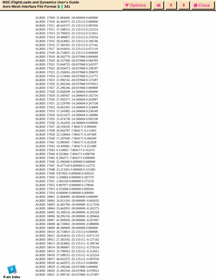
CloseOptionsMSC.FlightLoads and Dynamics User’s GuideAero Mesh Interface File Format § 341 Options
AGRID 17009 31.884000 -30.000000 0.000000 AGRID 17010 42.442075 -25.155112 0.000000 AGRID 17011 40.643375 -25.155112 0.087656 AGRID 17012 37.598515 -25.155112 0.225214 AGRID 17013 33.790053 -25.155112 0.313651 AGRID 17014 30.489607 -25.155112 0.276554 AGRID 17015 28.424065 -25.155112 0.196746 AGRID 17016 27.382592 -25.155112 0.127142 AGRID 17017 26.916016 -25.155112 0.071119 AGRID 17018 26.734853 -25.155112 0.000000 AGRID 17019 38.282779 -20.037868 0.000000 AGRID 17020 36.337580 -20.037868 0.094795 AGRID 17021 33.044725 -20.037868 0.243557 AGRID 17022 28.926073 -20.037868 0.339197 AGRID 17023 25.356816 -20.037868 0.299079 AGRID 17024 23.123040 -20.037868 0.212771 AGRID 17025 21.996742 -20.037868 0.137497 AGRID 17026 21.492164 -20.037868 0.076912 AGRID 17027 21.296246 -20.037868 0.000000 AGRID 17028 33.668299 -14.360604 0.000000 AGRID 17029 31.560567 -14.360604 0.102716 AGRID 17030 27.992577 -14.360604 0.263907 AGRID 17031 23.529789 -14.360604 0.367538 AGRID 17032 19.662301 -14.360604 0.324068 AGRID 17033 17.241882 -14.360604 0.230549 AGRID 17034 16.021475 -14.360604 0.148986 AGRID 17035 15.474738 -14.360604 0.083338 AGRID 17036 15.262450 -14.360604 0.000000 AGRID 17037 28.339230 -7.804171 0.000000 AGRID 17038 26.043797 -7.804171 0.111863 AGRID 17039 22.158064 -7.804171 0.287409 AGRID 17040 17.297849 -7.804171 0.400269 AGRID 17041 13.085947 -7.804171 0.352928 AGRID 17042 10.449981 -7.804171 0.251080 AGRID 17043 9.120892 -7.804171 0.162253 AGRID 17044 8.525466 -7.804171 0.090760 AGRID 17045 8.294273 -7.804171 0.000000 AGRID 17046 21.996000 0.000000 0.000000 AGRID 17047 19.477145 0.000000 0.122751 AGRID 17048 15.213201 0.000000 0.315383 AGRID 17049 9.879925 0.000000 0.439229 AGRID 17050 5.258064 0.000000 0.387279 AGRID 17051 2.365530 0.000000 0.275519 AGRID 17052 0.907077 0.000000 0.178046 AGRID 17053 0.253696 0.000000 0.099594 AGRID 17054 0.000000 0.000000 0.000000 AGRID 18001 31.884000 -30.000000 0.000000 AGRID 18002 32.051193 -30.000000 -0.065635 AGRID 18003 32.481790 -30.000000 -0.117338 AGRID 18004 33.442953 -30.000000 -0.181575 AGRID 18005 35.349216 -30.000000 -0.255228 AGRID 18006 38.395156 -30.000000 -0.289464 AGRID 18007 41.909939 -30.000000 -0.207847 AGRID 18008 44.720002 -30.000000 -0.080896 AGRID 18009 46.380000 -30.000000 0.000000 AGRID 18010 26.734853 -25.155112 0.000000 AGRID 18011 26.916016 -25.155112 -0.071119 AGRID 18012 27.382592 -25.155112 -0.127142 AGRID 18013 28.424065 -25.155112 -0.196746 AGRID 18014 30.489607 -25.155112 -0.276554 AGRID 18015 33.790053 -25.155112 -0.313651 AGRID 18016 37.598515 -25.155112 -0.225214 AGRID 18017 40.643375 -25.155112 -0.087656 AGRID 18018 42.442075 -25.155112 0.000000 AGRID 18019 21.296246 -20.037868 0.000000 AGRID 18020 21.492164 -20.037868 -0.076912 AGRID 18021 21.996742 -20.037868 -0.137497
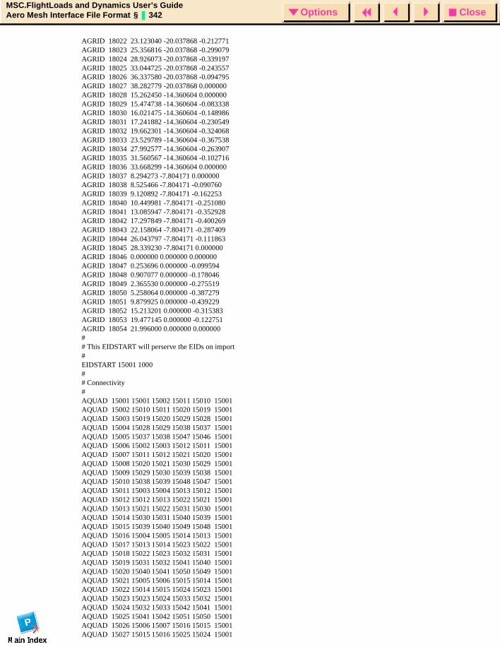
CloseOptionsMSC.FlightLoads and Dynamics User’s GuideAero Mesh Interface File Format § 342 Options
AGRID 18022 23.123040 -20.037868 -0.212771 AGRID 18023 25.356816 -20.037868 -0.299079 AGRID 18024 28.926073 -20.037868 -0.339197 AGRID 18025 33.044725 -20.037868 -0.243557 AGRID 18026 36.337580 -20.037868 -0.094795 AGRID 18027 38.282779 -20.037868 0.000000 AGRID 18028 15.262450 -14.360604 0.000000 AGRID 18029 15.474738 -14.360604 -0.083338 AGRID 18030 16.021475 -14.360604 -0.148986 AGRID 18031 17.241882 -14.360604 -0.230549 AGRID 18032 19.662301 -14.360604 -0.324068 AGRID 18033 23.529789 -14.360604 -0.367538 AGRID 18034 27.992577 -14.360604 -0.263907 AGRID 18035 31.560567 -14.360604 -0.102716 AGRID 18036 33.668299 -14.360604 0.000000 AGRID 18037 8.294273 -7.804171 0.000000 AGRID 18038 8.525466 -7.804171 -0.090760 AGRID 18039 9.120892 -7.804171 -0.162253 AGRID 18040 10.449981 -7.804171 -0.251080 AGRID 18041 13.085947 -7.804171 -0.352928 AGRID 18042 17.297849 -7.804171 -0.400269 AGRID 18043 22.158064 -7.804171 -0.287409 AGRID 18044 26.043797 -7.804171 -0.111863 AGRID 18045 28.339230 -7.804171 0.000000 AGRID 18046 0.000000 0.000000 0.000000 AGRID 18047 0.253696 0.000000 -0.099594 AGRID 18048 0.907077 0.000000 -0.178046 AGRID 18049 2.365530 0.000000 -0.275519 AGRID 18050 5.258064 0.000000 -0.387279 AGRID 18051 9.879925 0.000000 -0.439229 AGRID 18052 15.213201 0.000000 -0.315383 AGRID 18053 19.477145 0.000000 -0.122751 AGRID 18054 21.996000 0.000000 0.000000 ## This EIDSTART will perserve the EIDs on import#EIDSTART 15001 1000## Connectivity#AQUAD 15001 15001 15002 15011 15010 15001AQUAD 15002 15010 15011 15020 15019 15001AQUAD 15003 15019 15020 15029 15028 15001AQUAD 15004 15028 15029 15038 15037 15001AQUAD 15005 15037 15038 15047 15046 15001AQUAD 15006 15002 15003 15012 15011 15001AQUAD 15007 15011 15012 15021 15020 15001AQUAD 15008 15020 15021 15030 15029 15001AQUAD 15009 15029 15030 15039 15038 15001AQUAD 15010 15038 15039 15048 15047 15001AQUAD 15011 15003 15004 15013 15012 15001AQUAD 15012 15012 15013 15022 15021 15001AQUAD 15013 15021 15022 15031 15030 15001AQUAD 15014 15030 15031 15040 15039 15001AQUAD 15015 15039 15040 15049 15048 15001AQUAD 15016 15004 15005 15014 15013 15001AQUAD 15017 15013 15014 15023 15022 15001AQUAD 15018 15022 15023 15032 15031 15001AQUAD 15019 15031 15032 15041 15040 15001AQUAD 15020 15040 15041 15050 15049 15001AQUAD 15021 15005 15006 15015 15014 15001AQUAD 15022 15014 15015 15024 15023 15001AQUAD 15023 15023 15024 15033 15032 15001AQUAD 15024 15032 15033 15042 15041 15001AQUAD 15025 15041 15042 15051 15050 15001AQUAD 15026 15006 15007 15016 15015 15001AQUAD 15027 15015 15016 15025 15024 15001
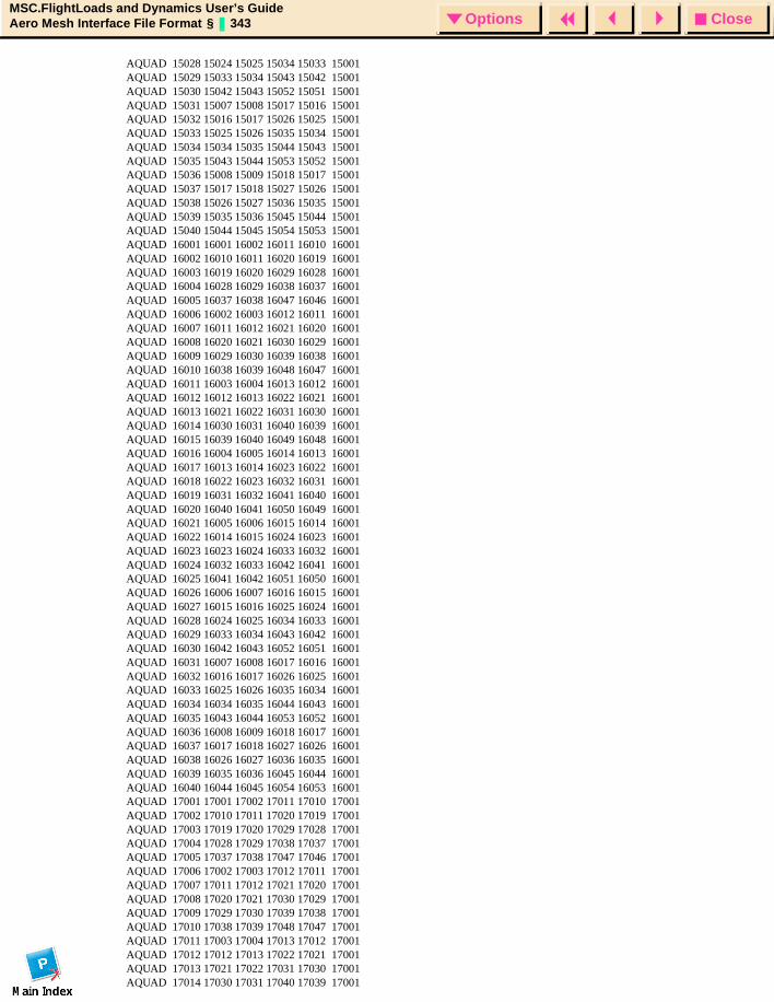
CloseOptionsMSC.FlightLoads and Dynamics User’s GuideAero Mesh Interface File Format § 343 Options
AQUAD 15028 15024 15025 15034 15033 15001AQUAD 15029 15033 15034 15043 15042 15001AQUAD 15030 15042 15043 15052 15051 15001AQUAD 15031 15007 15008 15017 15016 15001AQUAD 15032 15016 15017 15026 15025 15001AQUAD 15033 15025 15026 15035 15034 15001AQUAD 15034 15034 15035 15044 15043 15001AQUAD 15035 15043 15044 15053 15052 15001AQUAD 15036 15008 15009 15018 15017 15001AQUAD 15037 15017 15018 15027 15026 15001AQUAD 15038 15026 15027 15036 15035 15001AQUAD 15039 15035 15036 15045 15044 15001AQUAD 15040 15044 15045 15054 15053 15001AQUAD 16001 16001 16002 16011 16010 16001AQUAD 16002 16010 16011 16020 16019 16001AQUAD 16003 16019 16020 16029 16028 16001AQUAD 16004 16028 16029 16038 16037 16001AQUAD 16005 16037 16038 16047 16046 16001AQUAD 16006 16002 16003 16012 16011 16001AQUAD 16007 16011 16012 16021 16020 16001AQUAD 16008 16020 16021 16030 16029 16001AQUAD 16009 16029 16030 16039 16038 16001AQUAD 16010 16038 16039 16048 16047 16001AQUAD 16011 16003 16004 16013 16012 16001AQUAD 16012 16012 16013 16022 16021 16001AQUAD 16013 16021 16022 16031 16030 16001AQUAD 16014 16030 16031 16040 16039 16001AQUAD 16015 16039 16040 16049 16048 16001AQUAD 16016 16004 16005 16014 16013 16001AQUAD 16017 16013 16014 16023 16022 16001AQUAD 16018 16022 16023 16032 16031 16001AQUAD 16019 16031 16032 16041 16040 16001AQUAD 16020 16040 16041 16050 16049 16001AQUAD 16021 16005 16006 16015 16014 16001AQUAD 16022 16014 16015 16024 16023 16001AQUAD 16023 16023 16024 16033 16032 16001AQUAD 16024 16032 16033 16042 16041 16001AQUAD 16025 16041 16042 16051 16050 16001AQUAD 16026 16006 16007 16016 16015 16001AQUAD 16027 16015 16016 16025 16024 16001AQUAD 16028 16024 16025 16034 16033 16001AQUAD 16029 16033 16034 16043 16042 16001AQUAD 16030 16042 16043 16052 16051 16001AQUAD 16031 16007 16008 16017 16016 16001AQUAD 16032 16016 16017 16026 16025 16001AQUAD 16033 16025 16026 16035 16034 16001AQUAD 16034 16034 16035 16044 16043 16001AQUAD 16035 16043 16044 16053 16052 16001AQUAD 16036 16008 16009 16018 16017 16001AQUAD 16037 16017 16018 16027 16026 16001AQUAD 16038 16026 16027 16036 16035 16001AQUAD 16039 16035 16036 16045 16044 16001AQUAD 16040 16044 16045 16054 16053 16001AQUAD 17001 17001 17002 17011 17010 17001AQUAD 17002 17010 17011 17020 17019 17001AQUAD 17003 17019 17020 17029 17028 17001AQUAD 17004 17028 17029 17038 17037 17001AQUAD 17005 17037 17038 17047 17046 17001AQUAD 17006 17002 17003 17012 17011 17001AQUAD 17007 17011 17012 17021 17020 17001AQUAD 17008 17020 17021 17030 17029 17001AQUAD 17009 17029 17030 17039 17038 17001AQUAD 17010 17038 17039 17048 17047 17001AQUAD 17011 17003 17004 17013 17012 17001AQUAD 17012 17012 17013 17022 17021 17001AQUAD 17013 17021 17022 17031 17030 17001AQUAD 17014 17030 17031 17040 17039 17001
CloseOptionsMSC.FlightLoads and Dynamics User’s GuideAero Mesh Interface File Format § 344 Options
AQUAD 17015 17039 17040 17049 17048 17001AQUAD 17016 17004 17005 17014 17013 17001AQUAD 17017 17013 17014 17023 17022 17001AQUAD 17018 17022 17023 17032 17031 17001AQUAD 17019 17031 17032 17041 17040 17001AQUAD 17020 17040 17041 17050 17049 17001AQUAD 17021 17005 17006 17015 17014 17001AQUAD 17022 17014 17015 17024 17023 17001AQUAD 17023 17023 17024 17033 17032 17001AQUAD 17024 17032 17033 17042 17041 17001AQUAD 17025 17041 17042 17051 17050 17001AQUAD 17026 17006 17007 17016 17015 17001AQUAD 17027 17015 17016 17025 17024 17001AQUAD 17028 17024 17025 17034 17033 17001AQUAD 17029 17033 17034 17043 17042 17001AQUAD 17030 17042 17043 17052 17051 17001AQUAD 17031 17007 17008 17017 17016 17001AQUAD 17032 17016 17017 17026 17025 17001AQUAD 17033 17025 17026 17035 17034 17001AQUAD 17034 17034 17035 17044 17043 17001AQUAD 17035 17043 17044 17053 17052 17001AQUAD 17036 17008 17009 17018 17017 17001AQUAD 17037 17017 17018 17027 17026 17001AQUAD 17038 17026 17027 17036 17035 17001AQUAD 17039 17035 17036 17045 17044 17001AQUAD 17040 17044 17045 17054 17053 17001AQUAD 18001 18001 18002 18011 18010 18001AQUAD 18002 18010 18011 18020 18019 18001AQUAD 18003 18019 18020 18029 18028 18001AQUAD 18004 18028 18029 18038 18037 18001AQUAD 18005 18037 18038 18047 18046 18001AQUAD 18006 18002 18003 18012 18011 18001AQUAD 18007 18011 18012 18021 18020 18001AQUAD 18008 18020 18021 18030 18029 18001AQUAD 18009 18029 18030 18039 18038 18001AQUAD 18010 18038 18039 18048 18047 18001AQUAD 18011 18003 18004 18013 18012 18001AQUAD 18012 18012 18013 18022 18021 18001AQUAD 18013 18021 18022 18031 18030 18001AQUAD 18014 18030 18031 18040 18039 18001AQUAD 18015 18039 18040 18049 18048 18001AQUAD 18016 18004 18005 18014 18013 18001AQUAD 18017 18013 18014 18023 18022 18001AQUAD 18018 18022 18023 18032 18031 18001AQUAD 18019 18031 18032 18041 18040 18001AQUAD 18020 18040 18041 18050 18049 18001AQUAD 18021 18005 18006 18015 18014 18001AQUAD 18022 18014 18015 18024 18023 18001AQUAD 18023 18023 18024 18033 18032 18001AQUAD 18024 18032 18033 18042 18041 18001AQUAD 18025 18041 18042 18051 18050 18001AQUAD 18026 18006 18007 18016 18015 18001AQUAD 18027 18015 18016 18025 18024 18001AQUAD 18028 18024 18025 18034 18033 18001AQUAD 18029 18033 18034 18043 18042 18001AQUAD 18030 18042 18043 18052 18051 18001AQUAD 18031 18007 18008 18017 18016 18001AQUAD 18032 18016 18017 18026 18025 18001AQUAD 18033 18025 18026 18035 18034 18001AQUAD 18034 18034 18035 18044 18043 18001AQUAD 18035 18043 18044 18053 18052 18001AQUAD 18036 18008 18009 18018 18017 18001AQUAD 18037 18017 18018 18027 18026 18001AQUAD 18038 18026 18027 18036 18035 18001AQUAD 18039 18035 18036 18045 18044 18001AQUAD 18040 18044 18045 18054 18053 18001

CloseOptionsMSC.FlightLoads and Dynamics User’s GuideReferences § 345 Options
MSC.FlightLoads and Dynamics User’s Guide
References
References

CloseOptionsMSC.FlightLoads and Dynamics User’s GuideReferences § 346 Options
References1. Albano, E., and Rodden, W. P. (1969). A Doublet-Lattice Method for Calculating Lift
Distributions on Oscillating Surfaces in Subsonic Flows. AIAA J., Vol. 7, pp. 279-285, p. 2192.
2. Appa, Kari, Finite-Surface Spline, Journal of Aircraft, Vol. 26, No. 5, May 1989. pp.495-496
3. Chen, P. C., and Liu, D. D. (1985). A Harmonic Gradient Method for Unsteady Supersonic Flow Calculations. J. Aircraft, Vol. 22, pp. 371-379.
4. Giesing, J. P., Kalman, T. P., and Rodden, W. P. (1971). Subsonic Unsteady Aerodynamics for General Configurations; Part I, Vol. I - Direct Application of the Nonplanar Doublet-Lattice Method. Air Force Flight Dynamics Laboratory Report No. AFFDL-TR-71-5, Part I, Vol. I.
5. Giesing, J. P., Kalman, T., and Rodden, W. P. (1972a). Subsonic Unsteady Aerodynamics for General Configurations, Part II, Volume I - Application of the Doublet-Lattice-Method and the Method of Images to Lifting-Surface/Body Interference. Air Force Flight Dynamics Laboratory Report No. AFFDL-TR-71-5, Part II, Vol. I.
6. Giesing, J. P., Kalman, T. P., and Rodden, W. P. (1972b). Subsonic Unsteady Aerodynamics for General Configurations; Part II, Volume II - Computer Program N5KA. Air Force Flight Dynamics Laboratory Report No. AFFDL-TR-71-5, Part II, Vol. II.
7. Giesing, J. P., Kalman, T. P., and Rodden, W. P. (1972c). Subsonic Steady and Oscillatory Aerodynamics for Multiple Interfering Wings and Bodies. J. Aircraft, Vol. 9, pp. 693-702.
8. Hough, G.R., “Remarks on Vortex-Lattice Methods”, J. Aircraft, Vol. 10, No. 5, 1973, pp. 314-317.
9. Hough, G.R., “Lattice Arrangement for Rapid Convergence”, Vortex-Lattice Utilization, NASA SP-405, May 17-18, 1976, pp. 325-342.
10. Liu, D. D., James, D. K., Chen, P. C., and Pototzky, A. S. (1991). Further Studies of Harmonic Gradient Method for Supersonic Aeroelastic Applications. J. Aircraft, Vol. 28, pp. 598-605.
11. Rodden, W. P., Giesing, J. P., and Kalman, T. P. (1972). Refinement of the Nonplanar Aspects of the Subsonic Doublet-Lattice Lifting Surface Method. J. Aircraft, Vol. 9, pp. 69-73.
12. Rodden, W.P., and Johnson, E. H., (1994). MSC/NASTRAN Aeroelastic Analysis User’s Guide. The MacNeal-Schwendler Corporation.
13. Rodden, W. P., and Revell, J. D. (1962). The Status of Unsteady Aerodynamic Influence Coefficients. Institute of the Aeronautical Sciences, Fairchild Fund Paper No. FF-33.
14. Rubbert, P. E., “Theoretical Characteristics of Arbitrary Wings by a Non-Planar Vortex Lattice Method,” D6-9244, 1964, The Boeing Co., Renton, WA.
15. Anon, “MSC.Nastran Quick Reference Guide 2001”, MSC.Software Corporation, 2001.
O Q C A B D E F G H I J K L M N P R S T U V W X Y Z#
I N D E XMSC.FlightLoads and Dynamics User’s Guide
CloseOptionsMSC.FlightLoads and Dynamics User’s GuideIndex 347 Options
I N D E XMSC.FlightLoads and
Dynamics User’s Guide
AAccess Loads Data, 201Additional Body Data, 59aero group, 20Aero Groups Forms, 22, 27Aero Model Subforms, 156aero modeling, 17aero modeling options, 19aerodnynamic modeling
introduction, 18aerodynamic
elements, 262, 263extra points, 264
Aerodynamic and Aeroelastic Databases, 299, 300
aerodynamic database, 164aerodynamic influence coefficient, 264, 265Aerodynamic Modeling
Introduction, 18aerodynamic modeling
aero modeling options, 18control devices, 18flat plate aero modeling, 18model management, 18
aerodynamic modeling guidelines, 268aerodynamic theories, 264aeroelastic database, 164Aeroelastic Model, 154Aeroelastic Model Form, 155aeroelastic module, 128
aeroelastic model, 128aero-structure coupling, 128analysis, 128
Aeroelastic Solutions, 311Aeroelasticity, 99, 127
overview, 129Aero-Structure Coupling, 130aero-structure coupling, 129Albano, 265, 346analysis, 161architecture and capabilities, 3Attach Aero, 205
Attach XDB, 202
Bbasic aerodynamic coordinate frame, 19Basic Output Requests, 175bodies, 263
aspect ratio, 59interfence group ID, 59interference body theta values, 59mesh control, 57reference coord system, 59reference half-width, 59slender body half-widths, 59Y body, 52Z body, 52ZY body, 52
Body Forms, 31, 52boxes, 263Bulk Data Include File, 196
CChen, 266Control Devices
Overview, 72control devices, 72control surface, 73
chord length, 75hinge line, 75hinge moment, 75position limits, 75reference area, 75
coordinate, 194Create Body Forms, 53Create Control Surface Forms, 75Create Lifting Surface Forms, 33Create/Beam (General, Displacement, or
Force) Aero Body, 136Create/Beam (General, Displacement, or
Force) Aero Surface, 138Create/Beam Subforms, 139
O Q C A B D E F G H I J K L M N P R S T U V W X Y Z#
I N D E XMSC.FlightLoads and Dynamics User’s Guide
CloseOptionsMSC.FlightLoads and Dynamics User’s GuideIndex 348 Options
Create/Body Subforms, 56Create/Body/2 Points, 54Create/Body/Existing Curve, 53Create/Body/Point-Body, 55Create/Control Surface Subforms, 76Create/Control Surface/Lifting Surface, 75Create/Lifting Surface Subforms, 37Create/Lifting Surface/2 Curve/Edge, 35Create/Lifting Surface/2 Points/Chord, 36Create/Lifting Surface/4 Points, 34Create/Lifting Surface/Existing Surface, 33Create/Region, 211Create/Region Chain, 219Create/SuperGroup/Flat Plate, 23Create/Surface (General, Displacement, or
Force), 131Create/Surface Subforms, 133
DDefinitions for Spline Methods, 130Definitions for the Flat Plate Aero Modeling
Objects, 30Delete Any, Surface or Beam, 142Delete/Any, 68Delete/Body, 62Delete/Control Surface, 85, 91Delete/Region, 218Delete/Region Chain, 219Delete/SuperGroup/Flat Plate, 24Detach XDB/Aero, 206direct text input, 178, 197DIstributed Force Increments from Unit
Solutions, 320doublet lattice, 12doublet lattice method, 30doublet-lattice, 262, 263doublet-lattice method, 265, 267doublet-lattice subsonic lifting surface
theory, 265downwash, 263, 264downwash point, 263DZ, 289
Eexisting jobs, 191Export, 236, 237, 239Export - Output File Name Subform, 238external loads, 162
FFEM rigid body DOFs, 174Flat Plate Aero Modeling
Overview, 29flat plate aero modeling, 29
lifting surface, 30Y body, 30Z body, 30ZY body, 30
flexible increments, 162flexible trim, 162formats, 194Fringe Attributes, 51
GGetting Started, 7Giesing, 265, 267, 273, 276global data, 159graphical user interface, 13
working with FLDS forms, 13working with subforms, 14
Guidelines, 288
HHinge Line, Reference Chord Length, and
Reference Area, 79HP and HP0 Matrices, 325
IImport, 243
O Q C A B D E F G H I J K L M N P R S T U V W X Y Z#
I N D E XMSC.FlightLoads and Dynamics User’s Guide
CloseOptionsMSC.FlightLoads and Dynamics User’s GuideIndex 349 Options
Import/Export, 241INCLUDE files, 194Infinite Plate Spline and the Linear Spline,
280Inputs, 303Inputs and Outputs, 303integration matrix, 264Integration of MSC.Nastran and
MSC.Patran, 1, 4interference bodies, 270interference body, 273interference elements, 267interference group ID, 19interference groups, 270Introduction, 1, 100, 128, 242invoking MSC.FlightLoads and Dynamics,
10aero modeling, 12
JJames, 266jet engine, 276job parameters, 192j-set, 263
KKalman, 265, 267, 273, 276
Llifting surface
associated bodies, 41attributes, 45interference group ID, 41local coordinate system, 41mesh control, 37numbering, 41
Lifting Surface Forms, 30, 31Lifting Surface Methods, 32limits/hinge moment and position, 80
Liu, 266Loads Browser, 199
Introduction, 200Loads Tools, 208
MModel Management
Overview, 20model management, 20Model Management Forms, 22model parameters, 158Modify, Delete, and Show Body Forms, 60Modify, Delete, and Show Control Surface
Forms, 80Modify, Delete, and Show Lifting Surface
Forms, 42Modify/Any, 69Modify/Beam (General, Displacement, or
Force), 144Modify/Body and Modify/Any, 60Modify/Control Surface, 85Modify/Lifting Surface, 43Modify/Region, 216Modify/Region Chain, 219Modify/SuperGroup/Flat Plate, 25Modify/Surface (General, Displacement, or
Force), 143MSC.Nastran Aerodynamic Elements, 268MSC.Nastran Input File, 329
Introduction, 330MSC.Nastran Preference, 10
NNon-dimensional Option, 50Numbering Options, 195
OOptional Data Subform, 135, 141orphan group, 21
O Q C A B D E F G H I J K L M N P R S T U V W X Y Z#
I N D E XMSC.FlightLoads and Dynamics User’s Guide
CloseOptionsMSC.FlightLoads and Dynamics User’s GuideIndex 350 Options
Orphan Groups Forms, 22, 28
PPanel Aerodyamics
Introduction, 262Panel Aerodynamics, 261panel methods, 262Plot Load Summation, 232Plot Running Loads, 220Plot Running Loads - MSC.Patran Load
Cases, 221Plot Running Loads - Plot Options, 229Plot Running Loads - Results, 228Plot/LBCs/Load Summation, 232potential theory, 269Pototsky, 266prerequisites, 8
experience, 8software, 8structural model, 8
Pressure and Forces on the Aerodynamic Elements, 328
Printed Output, 321
RRebuild/Aero Groups/Flat Plate, 27Recovery of Unit Solutions to the a-set and to
the k-set, 319References, 345Restrained Analysis (Displacements
Relative to Equation ), 311Restrained Stability Derivatives from the
Unit Solutions, 314Results Interface via XDB, 293Revell, 264rigid trim, 162Rodden, 264, 265, 267, 273, 276, 346
SSelect Aero Model, 156Select File, 248Select Groups Subform, 134Select Structural Model, 157Select Surface, 140Select Surfaces Subform, 135Set Current/SuperGroup/Flat Plate, 26Show Attribute Information, 89, 146Show Splines, 145Show Surface or Beam/Attributes, 145Show/Body/Attributes and Mesh, 63Show/Body/Interference, 66Show/Control Surface/Attributes, 88Show/Lifting Surface/Aspect Ratio, 47Show/Lifting Surface/Boxes/Wave, 48Show/Orphan Groups/Flat Plate, 28Show/SuperGroup/Flat Plate, 26Slender and Interference Bodies, 273slender body, 273slender body elements, 267slender body theory, 267Spanwise Convergence Criteria, 271Spline Metrics, 292SPLINE2, 288SPLINE3, 289Splines, 277
Introduction, 278splines, 129
beam spline attachment flexibilities, 141displacement, 130Finite Plate spline, 131force, 130general, 130Harder-Demaris spline, 131Thin Plate splines, 131
Spring Attachments and Interpolation Smoothing, 287
Stability Derivatives and Hinge Moment Coefficients, 321
Static Aeroelastic Analysis, 307Introduction, 308

O Q C A B D E F G H I J K L M N P R S T U V W X Y Z#
I N D E XMSC.FlightLoads and Dynamics User’s Guide
CloseOptionsMSC.FlightLoads and Dynamics User’s GuideIndex 351 Options
static aeroelasticity, 161flexible increments, 162flexible trim, 162rigid trim, 162
Subcase Create-Flexible Trim, Rigid Trim, Flexible Increments, 167, 168, 169
subcase select, 190subsonic wing-body interference theory, 267substantial differentiation matrix, 264SuperGroup Forms, 22, 23
Ttarget database, 164Theoretical Development, 280Thin Plate Spline, 280translation parameters, 193Trim Parameter Use Subform, 172trim parameters, 170
control device, 170vehicle rigid body motion, 171
Trim Results and Control Surface Limits, 326Two Dimensional Finite Plate Spline, 284
UUnrestrained Analysis and Stability
Derivatives (Displacements Relative to Mean Axis), 315
VVerify/Displacement/Plot, 147vortex lattice method, 265
XXDB Output, 294
ZZ Body, Y Body and ZY Body, 52Zona Technology, Inc., 266ZONA51, 12, 30, 262, 263, 266ZONA51 supersonic lifting surface theory,
266


![Formless: A User's Guide, [excerpt] A User's Guide to Entropy](https://img.pdfslide.us/doc/110x75/586b77ce1a28ab9c7d8bebd4/formless-a-users-guide-excerpt-a-users-guide-to-entropy-.jpg)