Embed Size (px)
Citation preview

MSC800
Modular System Controller
O P E R AT I N G I N S T R U C T I O N S

Operating Instructions
MSC800 Modular System Controller
2 © SICK AG · Division Auto Ident · Germany · All rights reserved 8011540/RA36/2007-08-01
Software Versions
RF interference in case of use in residential areas!
The MSC800 Modular System Controller is exclusively for use in an industrial environment.
Copyright
Copyright © 2006 - 2007SICK AG WaldkirchAuto Ident, Reute PlantNimburger Strasse 1179276 ReuteGermany
Trademarks
Windows98TM, NTTM, METM, 2000TM, XPTM, VistaTM and Internet ExplorerTM are registered trademarks or trademarks of the Microsoft Corporation in the USA and other countries.
AcrobatTM ReaderTM is a trademark of Adobe Systems Incorporated.
Latest manual version
For the latest version of this manual (PDF), see www.sick.com.
Software/Tool Function Status
MSC800 SICK firmware From version 1.0 0000
MSC800 device description
Device-specific software module for SOPAS-ET Configuration Software
From version 1.00
SOPAS-ET Configuration Software From version 2.12

Operating Instructions
MSC800
Quick Finder
8011540/RA36/2007-08-01 © SICK AG · Division Auto Ident · Germany · All rights reserved 3
MSC800 Modular System Controller
Quick Finder …• Included in the delivery
– Chapter 3.1.6 Included in delivery, page 27
• System projection– Chapter 3.2 System requirements, page 28
• PLEASE NOTE!– Chapter 2 Safety information, page 17
• Installing the device in the reading station – Chapter 4 Installation, page 39
• Connecting the device – Chapter 5 Electrical installation, page 45
• Familiarizing yourself with the device and its functions– Chapter 3 Product description, page 21– Chapter 6.4 Default setting, page 79– Chapter 9 Technical data, page 87
• Starting up the device with the default setting– Chapter 6.3 First startup, page 76
• Installing the SOPAS-ET Configuration Software on the PC– Chapter 6.2.3 Installation of the SOPAS-ET Configuration Software, page 75
• Optimizing the device to the reading conditions– Chapter 6.3.3 Configuring the MSC800, page 78
• Assistance in case of problems– Chapter 8 Troubleshooting, page 85
• Where is everything? – Chapter Contents, page 5

Operating Instructions
MSC800 Modular System Controller
4 © SICK AG · Division Auto Ident · Germany · All rights reserved 8011540/RA36/2007-08-01
Quick Finder
Overview of installation sequence
The following list contains the most important installation steps for the MSC800 in combination with 1D/2D code sensors (ICR890 System, CLV490 Bar Code Scanner) and the VMS4xx/5xx Volume Measurement System:
1. Check delivery for completeness.2. Install the 1D/2D code sensors (ICR890 System, CLV490) and VMS4xx/5xx.3. Install the MSC800 close to the reading section.4. Install the photoelectric reflex switch and, if necessary, further sensors on the conveyor system
in front of the reading location against the direction of transport.5. If necessary, install the incremental encoder to the reading location on the conveyor system.6. Electrically connect the MSC800 to the 1D/2D code sensors.7. Connect the sensors as well as the data processing host and PC to the MSC800 configuration.8. Connect the MSC800 to the supply voltage (100 to 264 V AC/50 to 60 Hz).9. Switch on the MSC800 using the main switch.
The MSC800 and the connected sensors start automatically.10. Switch on the PC for configuration and install the SOPAS-ET Configuration Software (minimum
requirements: Windows 98TM).11. Start the SOPAS-ET Configuration Software and set up the new SOPAS-ET Project by selecting the
corresponding device descriptions.12. Establish communication with the MSC800.13. Configure the MSC800 and the 1D/2D code sensors via the register tabs in the SOPAS-ET
Configuration Software (code configuration, reading pulse, etc.).14. Adjust or optimize the 1D/2D code sensors.15. Carry out a test reading with the 1D/2D code. Move the object with the respective code(s) several
times across the conveyor level beneath the reading system and display the reading results in the SOPAS-ET Configuration Software.
16. Repeat the test reading under real conditions and check that the data has been transferred to the host.
17. Correct or optimize the parameter values where necessary via the SOPAS-ET Configuration Software.
18. Save the parameter set as an "*.spr" configuration file to the SOPAS-ET Configuration Software.The MSC800 is ready for operation once the application-specific setting has been set.
Note Detailed instructions can be found in Chapters 4 „Installation“, 5 „Electrical installation“ and 6 „Operation“.
Operating Instructions
MSC800
Contents
8011540/RA36/2007-08-01 © SICK AG · Division Auto Ident · Germany · All rights reserved 5
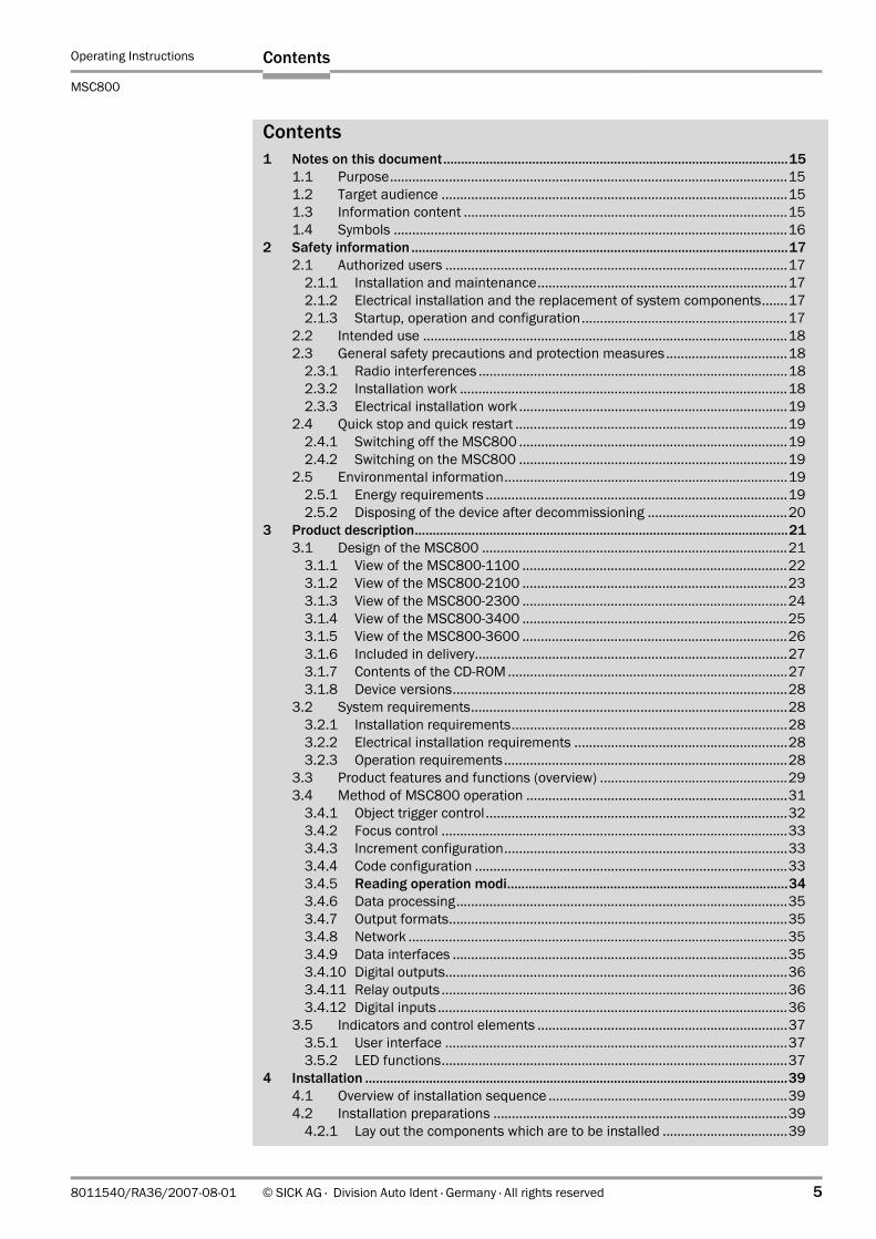
Contents1 Notes on this document.................................................................................................15
1.1 Purpose............................................................................................................151.2 Target audience ..............................................................................................151.3 Information content ........................................................................................151.4 Symbols ...........................................................................................................16
2 Safety information ..........................................................................................................172.1 Authorized users .............................................................................................17
2.1.1 Installation and maintenance....................................................................172.1.2 Electrical installation and the replacement of system components.......172.1.3 Startup, operation and configuration........................................................17
2.2 Intended use ...................................................................................................182.3 General safety precautions and protection measures.................................18
2.3.1 Radio interferences ....................................................................................182.3.2 Installation work .........................................................................................182.3.3 Electrical installation work .........................................................................19
2.4 Quick stop and quick restart ..........................................................................192.4.1 Switching off the MSC800 .........................................................................192.4.2 Switching on the MSC800 .........................................................................19
2.5 Environmental information.............................................................................192.5.1 Energy requirements ..................................................................................192.5.2 Disposing of the device after decommissioning ......................................20
3 Product description.........................................................................................................213.1 Design of the MSC800 ...................................................................................21
3.1.1 View of the MSC800-1100 ........................................................................223.1.2 View of the MSC800-2100 ........................................................................233.1.3 View of the MSC800-2300 ........................................................................243.1.4 View of the MSC800-3400 ........................................................................253.1.5 View of the MSC800-3600 ........................................................................263.1.6 Included in delivery.....................................................................................273.1.7 Contents of the CD-ROM ............................................................................273.1.8 Device versions...........................................................................................28
3.2 System requirements......................................................................................283.2.1 Installation requirements...........................................................................283.2.2 Electrical installation requirements ..........................................................283.2.3 Operation requirements.............................................................................28
3.3 Product features and functions (overview) ...................................................293.4 Method of MSC800 operation .......................................................................31
3.4.1 Object trigger control..................................................................................323.4.2 Focus control ..............................................................................................333.4.3 Increment configuration.............................................................................333.4.4 Code configuration .....................................................................................333.4.5 Reading operation modi...............................................................................343.4.6 Data processing..........................................................................................353.4.7 Output formats............................................................................................353.4.8 Network .......................................................................................................353.4.9 Data interfaces ...........................................................................................353.4.10 Digital outputs.............................................................................................363.4.11 Relay outputs ..............................................................................................363.4.12 Digital inputs...............................................................................................36
3.5 Indicators and control elements ....................................................................373.5.1 User interface .............................................................................................373.5.2 LED functions..............................................................................................37
4 Installation .......................................................................................................................394.1 Overview of installation sequence .................................................................394.2 Installation preparations ................................................................................39
4.2.1 Lay out the components which are to be installed ..................................39

Operating Instructions
MSC800 Modular System Controller
6 © SICK AG · Division Auto Ident · Germany · All rights reserved 8011540/RA36/2007-08-01
Contents
4.2.2 Lay out accessories ................................................................................... 394.2.3 Selecting the installation location............................................................. 404.2.4 Arrangement at the conveyor system....................................................... 41
4.3 Installation ...................................................................................................... 424.3.1 Installing the cabinet versions of the MSC800........................................ 424.3.2 Installing the MSC800-0000 Logic Controller unit .................................. 42
4.4 Installing external components ..................................................................... 434.4.1 Installing the 1D/2D code sensors........................................................... 434.4.2 External sensors for triggering .................................................................. 434.4.3 Installing the incremental encoder ........................................................... 434.4.4 Installing the MLG Light Grid or VMS4xx/5xx........................................... 44
4.5 Removing the system ..................................................................................... 445 Electrical installation...................................................................................................... 45
5.1 Overview of installation sequence................................................................. 455.2 Electrical installation of the MSC800 ........................................................... 465.3 Electrical connections .................................................................................... 47
5.3.1 Terminals for line voltage IN and supply voltage OUT ............................. 475.3.2 Electrical connections at the MSC800-0000 logic controller
(overview).................................................................................................... 555.3.3 Function of the LEDs of the logic controller .............................................. 57
5.4 Performing electrical installation................................................................... 585.4.1 Wire-cross sections .................................................................................... 585.4.2 Terminal strips............................................................................................ 595.4.3 Cable glands............................................................................................... 595.4.4 Connecting the shield ................................................................................ 615.4.5 Line safety switches/fuses........................................................................ 625.4.6 24 V DC supply voltage for the ICR890 Systems..................................... 635.4.7 24 V DC supply voltage for CLV490 and VMS4xx/5xx ............................ 665.4.8 HOST/AUX data interfaces of the logic controller.................................... 665.4.9 CAN 1/CAN 2 data interface of the logic controller................................. 675.4.10 Ethernet interface ETHERNET 1 of the logic controller ........................... 705.4.11 Switching inputs IN, TRIGGER and INC of the logic controller ................ 705.4.12 Switching outputs OUT of the logic controller .......................................... 72
5.5 Pin assignment of the connections and wire colour assignment ............... 735.5.1 Logic controller connections ..................................................................... 735.5.2 Wire colour assignment of assembled cables with open end ................ 74
6 Operation ......................................................................................................................... 756.1 Overview of the startup procedure ................................................................ 756.2 SOPAS-ET Configuration Software................................................................. 75
6.2.1 Functions of the SOPAS-ET Configuration Software for the MSC800 (overview).................................................................................... 75
6.2.2 System requirements for the SOPAS-ET Configuration Software ........... 756.2.3 Installation of the SOPAS-ET Configuration Software.............................. 756.2.4 Default setting for the SOPAS-ET Configuration Software....................... 76
6.3 First startup..................................................................................................... 766.3.1 Overview of the configuration procedure ................................................. 776.3.2 Establish communication with the MSC800............................................ 776.3.3 Configuring the MSC800 ........................................................................... 786.3.4 Load changed parameter set into the logic controller ............................ 796.3.5 Save, display and print the current parameter set .................................. 79
6.4 Default setting ................................................................................................ 796.4.1 Resetting the default setting in the MSC800 .......................................... 79
7 Maintenance.................................................................................................................... 817.1 Maintenance during operation ...................................................................... 817.2 Cleaning the MSC800 .................................................................................... 81
7.2.1 Cleaning the air inlet and air outlet openings (only MSC800-2100/-2300 and MSC800-3400/-3600) ....................... 81
Operating Instructions
MSC800
Contents
8011540/RA36/2007-08-01 © SICK AG · Division Auto Ident · Germany · All rights reserved 7
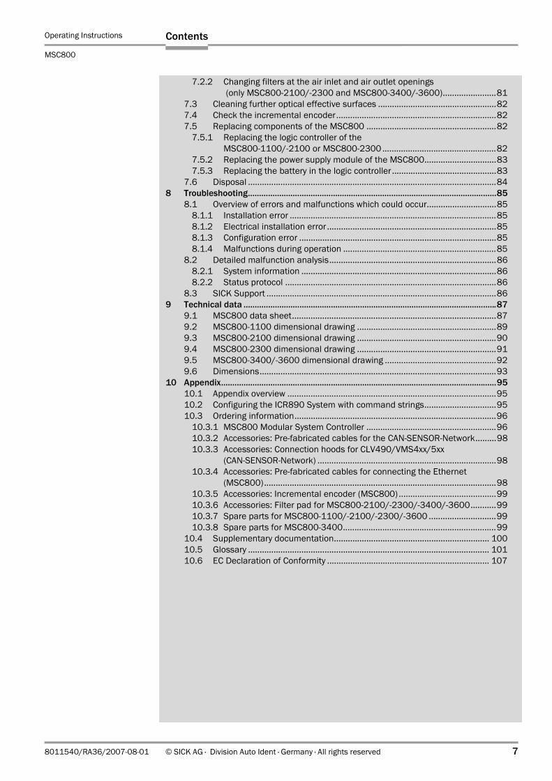
7.2.2 Changing filters at the air inlet and air outlet openings (only MSC800-2100/-2300 and MSC800-3400/-3600).......................81
7.3 Cleaning further optical effective surfaces ...................................................827.4 Check the incremental encoder.....................................................................827.5 Replacing components of the MSC800 ........................................................82
7.5.1 Replacing the logic controller of the MSC800-1100/-2100 or MSC800-2300 .................................................82
7.5.2 Replacing the power supply module of the MSC800...............................837.5.3 Replacing the battery in the logic controller .............................................83
7.6 Disposal ...........................................................................................................848 Troubleshooting...............................................................................................................85
8.1 Overview of errors and malfunctions which could occur..............................858.1.1 Installation error .........................................................................................858.1.2 Electrical installation error .........................................................................858.1.3 Configuration error .....................................................................................858.1.4 Malfunctions during operation ..................................................................85
8.2 Detailed malfunction analysis........................................................................868.2.1 System information ....................................................................................868.2.2 Status protocol ...........................................................................................86
8.3 SICK Support ...................................................................................................869 Technical data .................................................................................................................87
9.1 MSC800 data sheet........................................................................................879.2 MSC800-1100 dimensional drawing ............................................................899.3 MSC800-2100 dimensional drawing ............................................................909.4 MSC800-2300 dimensional drawing ............................................................919.5 MSC800-3400/-3600 dimensional drawing ................................................929.6 Dimensions......................................................................................................93
10 Appendix...........................................................................................................................9510.1 Appendix overview ..........................................................................................9510.2 Configuring the ICR890 System with command strings...............................9510.3 Ordering information.......................................................................................96
10.3.1 MSC800 Modular System Controller ........................................................9610.3.2 Accessories: Pre-fabricated cables for the CAN-SENSOR-Network.........9810.3.3 Accessories: Connection hoods for CLV490/VMS4xx/5xx
(CAN-SENSOR-Network) .............................................................................9810.3.4 Accessories: Pre-fabricated cables for connecting the Ethernet
(MSC800)....................................................................................................9810.3.5 Accessories: Incremental encoder (MSC800) ..........................................9910.3.6 Accessories: Filter pad for MSC800-2100/-2300/-3400/-3600...........9910.3.7 Spare parts for MSC800-1100/-2100/-2300/-3600 .............................9910.3.8 Spare parts for MSC800-3400..................................................................99
10.4 Supplementary documentation................................................................... 10010.5 Glossary ........................................................................................................ 10110.6 EC Declaration of Conformity ...................................................................... 107

Operating Instructions
MSC800 Modular System Controller
8 © SICK AG · Division Auto Ident · Germany · All rights reserved 8011540/RA36/2007-08-01
Contents

Operating Instructions
MSC800
Figures and tables
8011540/RA36/2007-08-01 © SICK AG · Division Auto Ident · Germany · All rights reserved 9
Abbreviations
BMP Bitmap (pixel-oriented Windows format for saving photos)
CAN Controller Area Network (field bus protocol based on the CAN bus)
CCD Charge Coupled Device
CLV Code Reader V principle
DOF Depth Of Field
EEPROM Electrically Erasable Programable Read Only Memory
FTP File Transfer Protocol
HTML Hyper Text Markup Language
I Input
ICD Image Capture Device (camera)
ICI Image Capture Illumination
ICR Image Code Reader (High-End CCD Camera System)
JPEG Joint Photographic Expert Group (pixel-oriented file format for saving high compression photos, compression process for tiff formats)
LED Light Emitting Diode
MAC Medium Access Control
MLG Modular Light Grid
MSC Modular System Controller (MSC800)
MTBF Mean Time Between Failure
MTTR Mean Time To Repair
NC contact Not closed contact
NO contact Not opened contact
O Output
PLC Programmable Logic Controller
PROM Programable Read Only Memory
RAM Random Access Memory
ROM Read Only Memory
SD Secure Digital Card
SMART SICK Modular Advanced Recognition Technology
SOPAS-ET SICK Open Portal for Application and Systems Engineering Tool (PC software for Windows for configuration of the ICR890 System and the MSC800)
TCP/IP Transmission Control Protocol/Internet Protocol
UDP User Datagram Protocol
VMS Volume Measurment System

Operating Instructions
MSC800 Modular System Controller
10 © SICK AG · Division Auto Ident · Germany · All rights reserved 8011540/RA36/2007-08-01
Figures and tables
Note The MSC800 Modular System Controller, the ICR890 System components as well as other components in this document are referred to in the following simplified terms:
• MSC800 Modular System Controller, simplified: MSC800• High End CCD Camera System, simplified: ICR890 System• ICD890 Image Capture Device, simplified: ICD890 Camera • ICI890 Image Capture Illumination, simplified: ICI890 Illumination• CLV490 Bar Code Scanner, simplified: CLV490• MLG (Modular Light Grid), simplified: MLG Light Grid• VMS4xx/5xx Volume Measuring System, simplified: VMS4xx/5xx• SICK Open Portal for Application and Systems Engineering Tool, simplified:
SOPAS-ET Configuration SoftwareThe ICR890 Systems and the CLV490 Bar Code Scanners are generally referred to as 1D/2D sensors.
The register tabs for configuration of the MSC800 are referred to in the online help of the SOPAS-ET Configuration Software as "device pages".
Operating Instructions
MSC800
Figures and tables
8011540/RA36/2007-08-01 © SICK AG · Division Auto Ident · Germany · All rights reserved 11
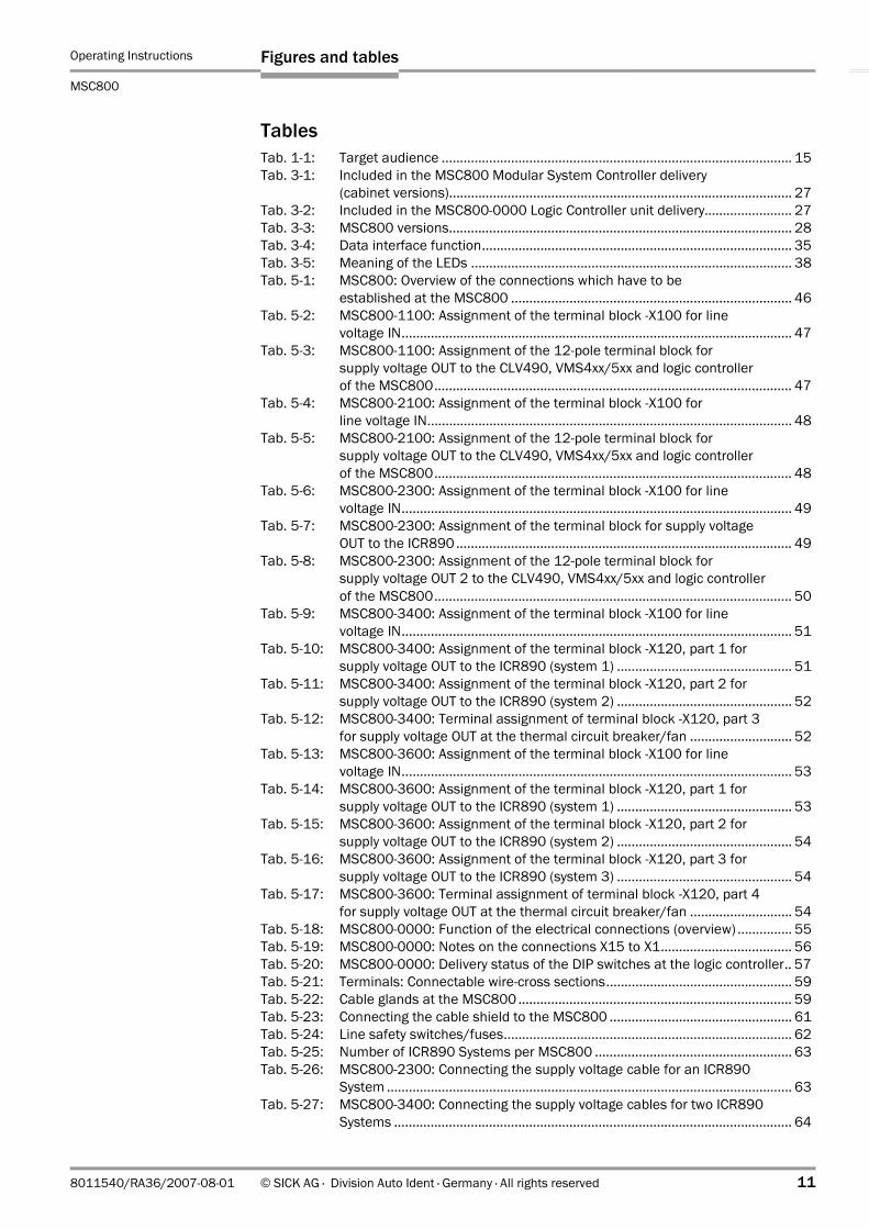
TablesTab. 1-1: Target audience ................................................................................................ 15Tab. 3-1: Included in the MSC800 Modular System Controller delivery
(cabinet versions).............................................................................................. 27Tab. 3-2: Included in the MSC800-0000 Logic Controller unit delivery........................ 27Tab. 3-3: MSC800 versions.............................................................................................. 28Tab. 3-4: Data interface function..................................................................................... 35Tab. 3-5: Meaning of the LEDs ........................................................................................ 38Tab. 5-1: MSC800: Overview of the connections which have to be
established at the MSC800 ............................................................................. 46Tab. 5-2: MSC800-1100: Assignment of the terminal block -X100 for line
voltage IN........................................................................................................... 47Tab. 5-3: MSC800-1100: Assignment of the 12-pole terminal block for
supply voltage OUT to the CLV490, VMS4xx/5xx and logic controller of the MSC800.................................................................................................. 47
Tab. 5-4: MSC800-2100: Assignment of the terminal block -X100 for line voltage IN.................................................................................................... 48
Tab. 5-5: MSC800-2100: Assignment of the 12-pole terminal block for supply voltage OUT to the CLV490, VMS4xx/5xx and logic controller of the MSC800.................................................................................................. 48
Tab. 5-6: MSC800-2300: Assignment of the terminal block -X100 for line voltage IN........................................................................................................... 49
Tab. 5-7: MSC800-2300: Assignment of the terminal block for supply voltage OUT to the ICR890 ............................................................................................ 49
Tab. 5-8: MSC800-2300: Assignment of the 12-pole terminal block for supply voltage OUT 2 to the CLV490, VMS4xx/5xx and logic controller of the MSC800.................................................................................................. 50
Tab. 5-9: MSC800-3400: Assignment of the terminal block -X100 for line voltage IN........................................................................................................... 51
Tab. 5-10: MSC800-3400: Assignment of the terminal block -X120, part 1 for supply voltage OUT to the ICR890 (system 1) ................................................ 51
Tab. 5-11: MSC800-3400: Assignment of the terminal block -X120, part 2 for supply voltage OUT to the ICR890 (system 2) ................................................ 52
Tab. 5-12: MSC800-3400: Terminal assignment of terminal block -X120, part 3 for supply voltage OUT at the thermal circuit breaker/fan ............................ 52
Tab. 5-13: MSC800-3600: Assignment of the terminal block -X100 for line voltage IN........................................................................................................... 53
Tab. 5-14: MSC800-3600: Assignment of the terminal block -X120, part 1 for supply voltage OUT to the ICR890 (system 1) ................................................ 53
Tab. 5-15: MSC800-3600: Assignment of the terminal block -X120, part 2 for supply voltage OUT to the ICR890 (system 2) ................................................ 54
Tab. 5-16: MSC800-3600: Assignment of the terminal block -X120, part 3 for supply voltage OUT to the ICR890 (system 3) ................................................ 54
Tab. 5-17: MSC800-3600: Terminal assignment of terminal block -X120, part 4 for supply voltage OUT at the thermal circuit breaker/fan ............................ 54
Tab. 5-18: MSC800-0000: Function of the electrical connections (overview) ............... 55Tab. 5-19: MSC800-0000: Notes on the connections X15 to X1.................................... 56Tab. 5-20: MSC800-0000: Delivery status of the DIP switches at the logic controller.. 57Tab. 5-21: Terminals: Connectable wire-cross sections................................................... 59Tab. 5-22: Cable glands at the MSC800........................................................................... 59Tab. 5-23: Connecting the cable shield to the MSC800 .................................................. 61Tab. 5-24: Line safety switches/fuses............................................................................... 62Tab. 5-25: Number of ICR890 Systems per MSC800 ...................................................... 63Tab. 5-26: MSC800-2300: Connecting the supply voltage cable for an ICR890
System ............................................................................................................... 63Tab. 5-27: MSC800-3400: Connecting the supply voltage cables for two ICR890
Systems ............................................................................................................. 64

Operating Instructions
MSC800 Modular System Controller
12 © SICK AG · Division Auto Ident · Germany · All rights reserved 8011540/RA36/2007-08-01
Figures and tables
Tab. 5-28: MSC800-3600: Connecting the supply voltage cables for three ICR890 Systems..............................................................................................................65
Tab. 5-29: Maximum cable lengths between the MSC800 and the host........................66Tab. 5-30: CAN bus: Maximum cable lengths, depending on the data transfer rate .....67Tab. 5-31: CAN bus: Maximum stub cable lengths, depending on the data
transfer rate .......................................................................................................68Tab. 5-32: CAN bus: Required wire cross section, depending on the data
cable length .......................................................................................................68Tab. 5-33: CAN bus: Maximum cable lengths, depending on the number of
CLV490s.............................................................................................................68Tab. 5-34: Ratings of the switching input TRIGGER_1......................................................71Tab. 5-35: Ratings of the digital switching outputs OUT_1 to OUT_4..............................72Tab. 5-36: Ratings of the relay outputs..............................................................................72Tab. 5-37: MSC800: Pin assignment of the 8-pole RJ-45 sockets "ETHERNET 1",
"ETHERNET 2" and "ETHERNET 3"....................................................................73Tab. 5-38: MSC800: Pin assignment of the 9-pole D-Sub connector "AUX 1" ................73Tab. 5-39: MSC800: Pin assignment of the 9-pole D-Sub connector "PROFIBUS" .........74Tab. 5-40: Wire colour assignment: Cables no. 6021166/no. 6021175 (CAN 1-IN),
PVC free..............................................................................................................74Tab. 6-1: Default setting for the SOPAS-ET Configuration Software (excerpt) ..............76Tab. 6-2: Connection between the PC with SOPAS-ET Configuration Software
and the MSC800 ...............................................................................................77Tab. 9-1: MSC800 technical specifications.....................................................................87Tab. 9-2: Dimensions shown in Fig. 9-1, page 89, Fig. 9-3, page 91
and Fig. 9-4, page 92...........................................................................................93Tab. 10-1: Ordering information: MSC800 Modular System Controller ..........................96Tab. 10-2: Accessories: Pre-fabricated cables for the CAN-SENSOR-Network................98Tab. 10-3: Accessories: Connection hoods for CLV490/VMS4xx/5xx
(CAN-SENSOR-Network ) ...................................................................................98Tab. 10-4: Accessories: Pre-fabricated cables for connecting the Ethernet
(MSC800)...........................................................................................................98Tab. 10-5: In stock accessories: Incremental encoder .....................................................99Tab. 10-6: In stock accessories: Filter pad for MSC800-2100/-2300/-3400/-3600....99Tab. 10-7: Ordering information: Spare parts for MSC800-1100/-2100/-2300/
-3600..................................................................................................................99Tab. 10-8: Ordering information: Spare parts for MSC800-3400....................................99Tab. 10-9: Supplementary documentation for the MSC800......................................... 100

Operating Instructions
MSC800
Figures and tables
8011540/RA36/2007-08-01 © SICK AG · Division Auto Ident · Germany · All rights reserved 13
FiguresFig. 3-1: MSC800 in combination with 1D/2D code sensors and external sensors .. 21Fig. 3-2: View of the MSC800-1100 (internal view and bottom view) ......................... 22Fig. 3-3: View of the MSC800-2100 (internal view and bottom view) ......................... 23Fig. 3-4: View of the MSC800-2300 (internal view and bottom view) ......................... 24Fig. 3-5: View of the MSC800-3400 (internal view and bottom view) ......................... 25Fig. 3-6: View of the MSC800-3600 (internal view and bottom view) ......................... 26Fig. 3-7: MSC800 in combination with 1D/2D code sensors and a conveyor
system................................................................................................................ 31Fig. 3-8: System diagram (top view) ............................................................................... 32Fig. 3-9: Reading operation modi in stand-alone operation, here
single-side-reading from top............................................................................. 34Fig. 3-10: Position of the SD memory card for parameter set at the logic controller ... 37Fig. 4-1: Example of a project-specific dimensional sheet for installation.................. 40Fig. 4-2: Arrangement of several ICR890 Systems at the conveyor system
with VMS4xx/5xx............................................................................................... 41Fig. 4-3: Arrangement of several CLV490 Bar Code Scanners at the
conveyor system ............................................................................................... 41Fig. 4-4: Position of the external components............................................................... 43Fig. 5-1: Block diagram: Connection principle of an MSC800 ..................................... 46Fig. 5-2: Terminals at the MSC800-1100 for line voltage IN and supply
voltage OUT ....................................................................................................... 47Fig. 5-3: Terminals at the MSC800-2100 for line voltage IN and supply
voltage OUT ....................................................................................................... 48Fig. 5-4: Terminals at the MSC800-2300 for line voltage IN and supply
voltage OUT ....................................................................................................... 49Fig. 5-5: Terminals at the MSC800-3400 for line voltage IN and supply
voltage OUT ....................................................................................................... 51Fig. 5-6: Terminals at the MSC800-3600 for line voltage IN and supply
voltage OUT ....................................................................................................... 53Fig. 5-7: MSC800-0000 logic controller in the cabinet of the MSC800-1100/
-2100/-2300: Position of the electrical connections..................................... 55Fig. 5-8: Connecting the braided shield of the cables at the inlet of the
housing (cable glands)...................................................................................... 61Fig. 5-9: Wiring of the data interfaces HOST (terminal block X3)/AUX
(terminal block X9)............................................................................................ 67Fig. 5-10: Wiring of the CAN interface with terminal resistance..................................... 69Fig. 5-11: Block diagram: Function of the Ethernet interface......................................... 70Fig. 5-12: Wiring of the switching input TRIGGER_1 ....................................................... 71Fig. 5-13: Wiring of the digital switching output OUT_1 (terminal block X7) ................. 72Fig. 5-14: Wiring of the relay outputs ............................................................................... 72Fig. 6-1: Configuration with SOPAS-ET ........................................................................... 76Fig. 7-1: Cleaning the air inlet and air outlet openings at the cabinet of
the MSC800 ...................................................................................................... 81Fig. 7-2: Releasing the power supply module................................................................ 83Fig. 7-3: MSC800: Position of the battery in the logic controller ................................. 84Fig. 9-1: MSC800-1100 dimensions.............................................................................. 89Fig. 9-2: MSC800-2100 dimensions.............................................................................. 90Fig. 9-3: MSC800-2300 dimensions.............................................................................. 91Fig. 9-4: MSC800-3400/-3600 dimensions.................................................................. 92Fig. 10-1: EC Declaration of Conformity for the MSC800-1100/-2100/-2300/
-3400/-3600 (page 1, scaled down version)................................................107Fig. 10-2: EC Declaration of Conformity for the MSC800-0000 (page 1,
scaled down version) ......................................................................................108

Operating Instructions
MSC800 Modular System Controller
14 © SICK AG · Division Auto Ident · Germany · All rights reserved 8011540/RA36/2007-08-01
Figures and tables
Notes:

Operating Instructions Chapter 1
MSC800
Notes on this document
8011540/RA36/2007-08-01 © SICK AG · Division Auto Ident · Germany · All rights reserved 15
1 Notes on this document
1.1 Purpose
This document provides instructions for technical staff on the installation and operation of the following MSC800 models:
– MSC800-0000: Logic controller (see also Chapter 2.2, page 18)
– MSC800-1100: Logic controller with a power supply unit (10 A) in a cabinet
– MSC800-2100: Logic controller with a power supply unit (10 A) in a cabinet
– MSC800-2300: Logic controller with a power supply unit (30 A) in a cabinet
– MSC800-3400: Power supply unit (40 A) in a cabinet
– MSC800-3600: Power supply unit (60 A) in a cabinet
Depending on the number of connected 1D/2D sensors, either an MSC800-1100/-2100 or an MSC800-2300 is used. The MSC800-2300 can be combined with further MSC800-3400s or MSC800-3600s to increase the total power of the power supply units.
This document contains the following information:
• Installation and electrical installation• Startup• Operation and configuration• Maintenance• Troubleshooting• Replacing system componentsA step-by-step approach is taken for all tasks.
1.2 Target audience
The target audience of this document is persons assigned the following tasks:
1.3 Information content
This document contains all the required information for installation, electrical installation and startup of the MSC800 on site.
Configuration of the MSC800 for the application-specific reading conditions and operation is carried out via the SOPAS-ET Configuration Software at a WindowsTM-PC. The SOPAS-ET Configuration Software contains an online help system to facilitate configuration.
Note Further information on High End CCD Camera Systems, Volume Measurement Systems and Bar Code Scanners is available from SICK AG, Auto Ident division. On the Internet at www.sick.com.
Tasks Target audience
Installation, electrical installation, maintenance, replacing system components
Qualified staff, e. g. service technicians and factory electricians
Startup and configuration Qualified staff, e. g. technicians or engineers
Operation of the conveyor system Qualified staff for startup and operation of the conveyor system
Tab. 1-1: Target audience

Chapter 1 Operating Instructions
MSC800 Modular System Controller
16 © SICK AG · Division Auto Ident · Germany · All rights reserved 8011540/RA36/2007-08-01
Notes on this document
1.4 Symbols
Some of the information in this document is marked specially so that you can access it quickly:
Warning
Warnings are provided to prevent injury to operating personnel or serious damage to the MSC800.
Always read warnings carefully and observe them at all times.
Reference Italics are used to refer to more detailed information elsewhere.
Note Notes indicate special features or characteristics.
Explanation Explanations provide background information on technical correlations.
Recommendation Recommendations help you carry out certain procedures more effectively.
TIP Tips explain settings in the SOPAS-ET Configuration Software.
PROJECT This font indicates a term in the user interface of the SOPAS-ET Configuration Software.
Icons refer to buttons in the user interface of the SOPAS-ET Configuration Software.
"0x0" This font indicates messages output by the MSC800.
This symbol identifies sections that describe steps carried out with the SOPAS-ET Configuration Software.
This symbol refers to additional technical documentation.
There is a procedure which needs to be carried out. This symbol indicates operational instructions which only contain one operational step or operational steps in warning notices which do not have to be followed in any particular order.
Operational instructions comprising several steps are denoted using consecutive numbers.
This symbol indicates a glossary entry.

Operating Instructions Chapter 2
MSC800
Safety information
8011540/RA36/2007-08-01 © SICK AG · Division Auto Ident · Germany · All rights reserved 17
2 Safety informationThis chapter deals with your safety and operator safety.
Read this chapter carefully before using the MSC800.
2.1 Authorized users
To ensure correct and safe functioning, the MSC800 must be installed, operated and maintained by sufficiently qualified staff.
Repairs to the MSC800 should only be carried out by qualified and authorized SICK AG service staff.
The operating instructions should be made available to the end user.
The end user should be briefed and urged to read the operating instructions by the technicians.
The following chapters summarize the required qualifications for the various tasks.
2.1.1 Installation and maintenance
• Practical technical training
• Knowledge of current health and safety regulations at the workplace
2.1.2 Electrical installation and the replacement of system components
• Practical electrical training
• Knowledge of current electrical safety regulations
• Knowledge of startup and operation of the device in each operational area (e. g. conveyor system)
2.1.3 Startup, operation and configuration
• Knowledge of the mechanical and electrical parameters of the conveyor system and the characteristics of the conveyor system regarding startup and operation
• Basic knowledge of the WindowsTM operating system
• Basic knowledge of data transfer
• Basic knowledge of designing and setting up (addressing) Ethernet connections for connecting the MSC800 to the Ethernet
• Basic knowledge of working with an HTML browser (e. g. Internet Explorer) for using the online help
• Basic knowledge of 1D/2D code technology

Chapter 2 Operating Instructions
MSC800 Modular System Controller
18 © SICK AG · Division Auto Ident · Germany · All rights reserved 8011540/RA36/2007-08-01
Safety information
2.2 Intended use
The MSC800 Modular System Controller is used in combination with a corresponding number of 1D/2D code sensors and a VMS4xx/5xx. The logic controller of the MSC800 assumes coordination of the sensors.
The intended use of the MSC800 results from the following description of the system components and their functions:
• The 1D/2D code sensors are powered by the power supply unit of the MSC800.
• In combination with the MSC800 the 1D/2D sensors transfer their data via a CAN in-terface to the MSC800. The data can then be accessed from the HOST data interface.
• The configuration/operation of the MSC800 is carried out via the AUX auxiliary inter-face (serial RS 232 or Ethernet) using the SOPAS-ET Configuration Software, which runs on a standard client PC.
• As a separate component the MSC800-0000 Logic Controller is desigend for installa-tion in to a system that is resold or integrated into a third part system. The component has to be installed in a metal control cabinet. To do so, see for the installation require-ments in Chapter 4.3.2, page 42.
Any warranty claims against SICK AG shall be deemed invalid in the case of other system use or system modifications, this includes modifications during installation and electrical installation or changes to the SICK software.
2.3 General safety precautions and protection measures
Read the general safety precautions thoroughly and observe them during all MSC800 activities. Also observe the warning notices above the operational instructions of each chapter.
2.3.1 Radio interferences
RF interference in case of use in residential areas!
The MSC800 Modular System Controller is exclusively for use in an industrial environment.
2.3.2 Installation work
Risk of injuries due to falling components!
The weight of the MSC800 is approx. 10 to 20 kg (22 to 44 lb) depending on the version.
Do not carry out installation work alone.
A second person should always secure components during installation.

Operating Instructions Chapter 2
MSC800
Safety information
8011540/RA36/2007-08-01 © SICK AG · Division Auto Ident · Germany · All rights reserved 19
2.3.3 Electrical installation work
Risk of injuries due to electrical current!
The MSC800 is connected to the power supply (100 to 264 V AC/50 to 60 Hz).
Observe current safety regulations when working with electrical equipment.
2.4 Quick stop and quick restart
The MSC800 can be switched on and off via a main switch.
2.4.1 Switching off the MSC800
Switching off the supply voltage to the MSC800.
When the MSC800 is switched off the following data is lost:
• Application-specific parameter sets in the logic controller of the MSC800 and in the 1D/2D code sensors which were only temporarily saved in the devices
• The last reading result
• Daily operating hours counter
2.4.2 Switching on the MSC800
Switching on the supply voltage to the MSC800.The MSC800 starts up using the most recent permanently saved configuration. The daily operating hours counter is reset.
2.5 Environmental information
The MSC800 has been constructed with minimum environmental pollution in mind.
2.5.1 Energy requirements
The 1D/2D code sensors are electrically powered via the power supply unit of the MSC800 as standard (24 V DC functional extra-low voltage in accordance with IEC 364-4-41).
The system components have the following power consumption:
• MSC800-0000 (logic controller): typically 10 W with 24 V DC ± 10 % (logic controller only in MSC800-1100, MSC800-2100 or MSC800-2300)
• ICR890 System: typically 425 W with 24 V DC ± 10 % (via the MSC800-2300, MSC800-3400 or MSC800-3600 power supply unit)
• CLV490: typically 18 W with 24 V DC ± 10 % (via the MSC800-1100, MSC800-2100, MSC800-2300, MSC800-3400 or MSC800-3600 power supply unit)
• VMS410/510: typically 25 W with 24 V DC ± 10 % ((via the MSC800-1100, MSC800-2100, MSC800-2300, MSC800-3400 or MSC800-3600 power supply unit)
• VMS420/520: typically 50 W with 24 V DC ± 10 % ((via the MSC800-1100, MSC800-2100, MSC800-2300, MSC800-3400 or MSC800-3600 power supply unit)

Chapter 2 Operating Instructions
MSC800 Modular System Controller
20 © SICK AG · Division Auto Ident · Germany · All rights reserved 8011540/RA36/2007-08-01
Safety information
2.5.2 Disposing of the device after decommissioning
SICK AG does not currently accept the return of any devices which can no longer be operated or repaired.
Inoperable or irreparable devices must be disposed of in an environmentally friendly manner and in accordance with valid country-specific waste disposal guidelines.
The design of the MSC800 allows for its separation as recyclable secondary raw materials and hazardous waste (electronic scrap).
Please see Chapter 7.6 Disposal, page 84.
Note The battery in the logic controller of the MSC800 must be removed before the device is scrapped.
Dispose of the battery separately in accordance with ROHS regulations (Europe).

Operating Instructions Chapter 3
MSC800
Product description
8011540/RA36/2007-08-01 © SICK AG · Division Auto Ident · Germany · All rights reserved 21
3 Product descriptionThis chapter describes the design, the features and the functions of the MSC800.
For installation, electrical installation and startup assistance as well as for configuration of the logic controller of the MSC800 using the SOPAS-ET Configuration Software, please read this chapter prior to carrying out any of the tasks.
3.1 Design of the MSC800
The MSC800 consists of a logic controller and a power supply unit in a cabinet. The MSC800 is used in combination with 1D/2D code sensors and a VMS4xx/5xx (detection of the object geometry). The sensors are connected to the logic controller of the MSC800 via the CAN bus. The power supply unit of the MSC800 provides the supply voltage for the sensors.
External sensors are required for the reading pulse, detection of the object distance (with MLG, alternative to VMS4xx/5xx, application-dependent) and for generation of the increment signal. These sensors and the superordinate host processor are also connected to the MSC800.
Fig. 3-1: MSC800 in combination with 1D/2D code sensors and external sensors
MSC800
Supply voltageMains connection
ICR890 System
CAN bus
HOST
Reading pulseConveyor speed
MLG Light Grid
Object distance(optional)
VMS4xx/5xx CLV490
Object geometry
1D/2D sensors

Chapter 3 Operating Instructions
MSC800 Modular System Controller
22 © SICK AG · Division Auto Ident · Germany · All rights reserved 8011540/RA36/2007-08-01
Product description
3.1.1 View of the MSC800-1100
Fig. 3-2: View of the MSC800-1100 (internal view and bottom view)
Legend:1 Terminals for line voltage IN
2 Line safety switch for safety plug socket and power supply module
3 Power supply module 10 A for 24 V DC supply voltage
4 Safety plug socket (line voltage)
5 Fuses for 24 V DC supply voltage
6 Terminals for supply voltage OUT (24 V DC, max. 10 A)
7 Logic controller with connections and SD memory card for parameter cloning
8 Cable glands (M cable glands)
9 Mounting bracket for fixing (x 2)
8
9
2
1
3 4
6
5
7
Operating Instructions Chapter 3
MSC800
Product description
8011540/RA36/2007-08-01 © SICK AG · Division Auto Ident · Germany · All rights reserved 23
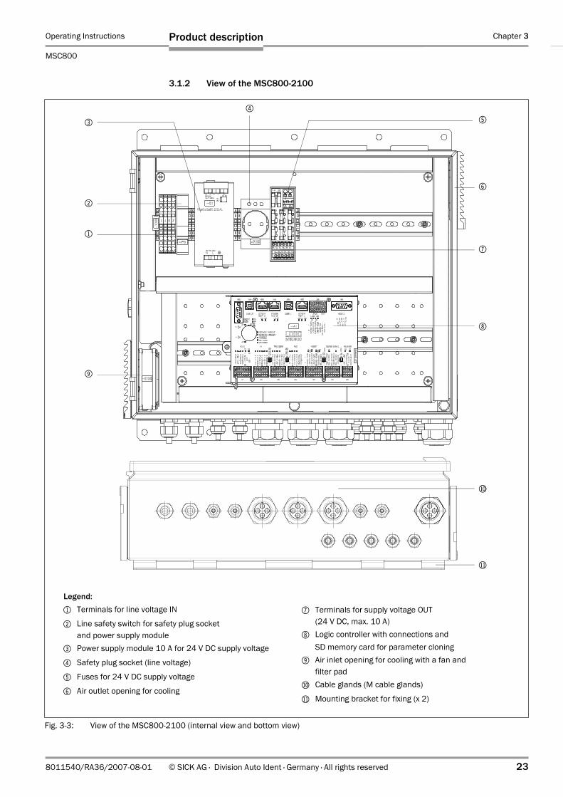
3.1.2 View of the MSC800-2100
Fig. 3-3: View of the MSC800-2100 (internal view and bottom view)
7
Legend:1 Terminals for line voltage IN
2 Line safety switch for safety plug socket and power supply module
3 Power supply module 10 A for 24 V DC supply voltage
4 Safety plug socket (line voltage)
5 Fuses for 24 V DC supply voltage
6 Air outlet opening for cooling
7 Terminals for supply voltage OUT (24 V DC, max. 10 A)
8 Logic controller with connections and SD memory card for parameter cloning
9 Air inlet opening for cooling with a fan andfilter pad
bl Cable glands (M cable glands)
bm Mounting bracket for fixing (x 2)
6
3
4
5
2
1
9
bl
8
bm

Chapter 3 Operating Instructions
MSC800 Modular System Controller
24 © SICK AG · Division Auto Ident · Germany · All rights reserved 8011540/RA36/2007-08-01
Product description
3.1.3 View of the MSC800-2300
Fig. 3-4: View of the MSC800-2300 (internal view and bottom view)
Legend:1 Terminals for line voltage IN
3 Line safety switch for safety plug socket and power supply modules
2 Safety plug socket (line voltage)
4 Power supply modules 10 A for 24 V DC supply voltage
5 Terminals for supply voltage OUT (24 V DC, max. 20 A)
6 Air outlet opening for cooling
7 Fuses for 24 V DC supply voltage
8 Terminals for supply voltage OUT (24 V DC, max. 10 A)
9 Logic controller with connections and SD memory card for parameter cloning
bl Air inlet opening for cooling with a fan andfilter pad
bm Cable glands (M cable glands)
bn Mounting bracket for fixing (x 2)
bm
bn
8
6
3
4
5
2
1
7
bl
9

Operating Instructions Chapter 3
MSC800
Product description
8011540/RA36/2007-08-01 © SICK AG · Division Auto Ident · Germany · All rights reserved 25
3.1.4 View of the MSC800-3400
Fig. 3-5: View of the MSC800-3400 (internal view and bottom view)
5
Legend:1 Air inlet opening for cooling with a fan and filter pad
2 Thermal circuit breaker with NC contact for excess temperature signalling
3 Air outlet opening for cooling
4 Power supply modules 20 A for 24 V DC supply voltage
5 Thermal circuit breaker with NO contact for switching the fan on and off
6 Fuse for fan
7 Terminals for NC contact (thermal circuit breaker)
8 Terminal sets for supply voltage OUT 2 to 1 (24 V DC, 2 x max. 20 A)
9 Automatic circuit breakers (supply voltage OUT 2)
bl Automatic circuit breakers (supply voltage OUT 1)
bm Line safety switch for power supply modules
bn Terminals for line voltage IN
bo Cable glands (M cable glands)
bp Mounting bracket for fixing (x 2)
67
2
bm bl
1 1
9
4
bo
bp
8bn
3 3

Chapter 3 Operating Instructions
MSC800 Modular System Controller
26 © SICK AG · Division Auto Ident · Germany · All rights reserved 8011540/RA36/2007-08-01
Product description
3.1.5 View of the MSC800-3600
Fig. 3-6: View of the MSC800-3600 (internal view and bottom view)
Legend:1 Air inlet opening for cooling with a fan and
filter pad2 Thermal circuit breaker with NC contact for
excess temperature signalling3 Air outlet opening for cooling
4 Power supply modules 10 A for 24 V DC supply voltage
5 Thermal circuit breaker with NO contact for switching the fan on and off
6 Fuse for fan
7 Terminals for NC contact (thermal circuit breaker)
8 Terminal sets for supply voltage OUT 3 to 1 (24 V DC, 3 x max. 20 A)
9 Automatic circuit breakers (supply voltage OUT 3)
bl Automatic circuit breakers (supply voltage OUT 2)
bm Automatic circuit breakers (supply voltage OUT 1)
bn Line safety switch for power supply modules
bo Terminals for line voltage IN
bp Cable glands (M cable glands)
bq Mounting bracket for fixing (x 2)
5
67
2
bm bl
1 1
9
4
bp
bq
8bnbo
3 3

Operating Instructions Chapter 3
MSC800
Product description
8011540/RA36/2007-08-01 © SICK AG · Division Auto Ident · Germany · All rights reserved 27
3.1.6 Included in delivery
Cabinet versions
Delivery of the MSC800 in a cabinet includes the following components:
Logic Controller unit
Delivery of the MSC800-0000 includes the following components:
An overview of the device versions, in stock accessories, incremental encoders, cables and plug connections is available in Chapter Command listing on request., page 95.
3.1.7 Contents of the CD-ROM
• “SOPAS-ET Engineering Tool“: Configuration software for WindowsTM PCs with integrated online help system (HTML files)
• Operating Instructions MSC800: PDF available in German and English as well as other publications for ICR890, VMS4xx/5xx, CLV6xx and more
• "Acrobat Reader": Freely available PC software for reading PDF files
Note The current versions of publications and programs on the CD-ROM can also be downloaded at www.sick.com.
Piece Components Comment
1 MSC800-1100- or -MSC800-2100- or -MSC800-2300
Without connection cables
MSC800-3400 Further power supply modules for supplying the 1D/2D code sensors
MSC800-3600 Further power supply modules for supplying the 1D/2D code sensors
1 Notes On Device for initial information (No. 8011538)
Included in the device packaging of the MSC800
1 CD-ROM "Manual & Software Auto Ident"
Operating Instructions MSC800 in printed form, in German and/or English
Optional, depending on the number of issues explicitly ordered upon purchase
Tab. 3-1: Included in the MSC800 Modular System Controller delivery (cabinet versions)
Piece Components Comment
1 MSC800-0000 Without connection cables
1 Notes On Device for initial information (No. 8012115)
Included in the device packaging of the MSC800-0000
1 CD-ROM "Manual & Software Auto Ident"
Operating Instructions MSC800 in printed form, in German and/or English
Optional, depending on the number of issues explicitly ordered upon purchase
Tab. 3-2: Included in the MSC800-0000 Logic Controller unit delivery

Chapter 3 Operating Instructions
MSC800 Modular System Controller
28 © SICK AG · Division Auto Ident · Germany · All rights reserved 8011540/RA36/2007-08-01
Product description
3.1.8 Device versions
The MSC800 is, amongst other things, available in the following versions:
The MSC800-2300 can be combined with further MSC800-3400s/-3600s. Further versions can be supplied upon request.
3.2 System requirements
3.2.1 Installation requirements
• Stable installation frame with sufficient load capacity and measurements suited to the cabinet of the MSC800 (see Chapter 9.2, page 89, Chapter 9.4, page 91, Chapter 9.5, page 92)
• Shock absorbent and vibration free attachment
3.2.2 Electrical installation requirements
• Supply voltage: 100 to 264 V AC/50 to 60 Hz• Reading pulse sensor (start/stop), e. g. photoelectric reflex switch (included in
delivery): For registering an object with external reading pulse• Additional appropriate reading pulse sensor (stop), e. g. photoelectric reflex switch: For
registering the end of pulse with extended external reading pulse• Optionally, a suitable incremental encoder, e. g. no. 2039455 (resolution 10 mm
(394 mil))/pulse) or no. 2039457 (resolution 0.2 mm (7.9 mil)/pulse) when using the VMS4xx/5xx.Device is included in delivery depending on the system configuration
• Host processor with data interface RS 232, RS 422/485, Ethernet or PROFIBUS-DP: for further processing of the reading data
• Suitable visualization PC or PLC: To display the system status
3.2.3 Operation requirements
• PC in the following version:– Minimum Pentium II (recommended Pentium III), 350 MHz (recommended
500 MHz), 64 MB RAM (recommended 128 MB), CD drive, RS 232 serial data interface or Ethernet interface card, mouse (recommended) and colour monitor (recommended resolution 1,024 x 768 pixels)
Type Order no. Description
MSC800-0000 1040571 Logic controller unit*)
MSC800-1100 1040385 Logic controller with power supply unit (10 A), cabinet 300 x 400 x 155 mm3, without fan
MSC800-2100 1041611 Logic controller with power supply unit (10 A), cabinet 500 x 400 x 155 mm3, with one fan
MSC800-2300 1040386 Logic controller with power supply unit (30 A), cabinet 500 x 400 x 155 mm3, with one fan
MSC800-3400 1041770 Additional power supply unit (40 A), cabinet 500 x 400 x 155 mm3, with two fans,in combination with MSC800-2100/-2300
MSC800-3600 1040387 Additional power supply unit (60 A), cabinet 500 x 400 x 155 mm3, with two fans, in combination with MSC800-2100/-2300
*) For installation requirements see Chapter 4.3.2, Page 42
Tab. 3-3: MSC800 versions

Operating Instructions Chapter 3
MSC800
Product description
8011540/RA36/2007-08-01 © SICK AG · Division Auto Ident · Germany · All rights reserved 29
– Operating system Windows 98TM, Windows NT4.0TM, Windows METM, Windows 2000TM, Windows XPTM or Windows VistaTM
– Free storage space on the hard drive: Approx. 100 MB for SOPAS-ET Configuration Software (V. 2.12) with help files and approx. 70 MB for "Acrobat Reader"
• PC HTML browser, e. g. Internet ExplorerTM: For online help system to the SOPAS-ET Configuration Software
3.3 Product features and functions (overview)
User safety and convenience
• Cabinet versions: robust, compact metal cabinet, enclosure rating IP 65/IP 54, CE mark
• Automatic self-test on system startup• Diagnosis tools for system setup and remote system monitoring• Configurable reading diagnosis data display in two reading result formats• Operational data retrieval, error code display on request in case of errors• Activatable test string function (heartbeat) for signalling readiness for operation• Password protected configuration mode• Additional back up of configuration parameter values (cloning) on SD memory card (can
be removed when replacing the logic controller)• Future proof due to firmware update (flash PROM) via data interface• Future proof SOPAS-ET Configuration Software• Extended power supply scope (line voltage IN)• Cabinet cooling using the fan (not MSC800-1100)• Signalling possibility for excess cabinet temperature (only MSC800-1100/-2100/
-2300)• Replacement of MSC800 components (logic controller, power supply module) possible
within 5 minutes
Convenient operation/configuration
• Configuration (online/offline) and display of image memory contents via the SOPAS-ET Configuration Software (incl. help system)
• Status indicators of connections of the logic controller via LEDs
Reading operation modi
• Start/Stop operation• Object tracking
1D/2D code detection
• ECC200 Data Matrix (PDF417 in preparation)/all conventional bar codes• Separation of identical codes of the same code type using the position in the image
memory respectively the reading angle along the scaning line
Data processing
• Manipulation of the reading data by event-dependent evaluation conditions• Manipulation the of output data string via filter or sorter

Chapter 3 Operating Instructions
MSC800 Modular System Controller
30 © SICK AG · Division Auto Ident · Germany · All rights reserved 8011540/RA36/2007-08-01
Product description
Data communication
• Main data interface HOST: 2 configurable output formats of the reading result, communication redirectable to several physical data interfaces, parallel operating of the interfaces possible
• Auxiliary data interface AUX: Permanent output format with special diagnosis functions, communication redirectable to to several physical data interfaces, parallel operating of the interfaces possible
Reading pulse
• External reading pulse via switching input(s) or data interface
Electrical interfaces
• HOST data interface: RS 232, RS 422/485 serial, Ethernet or PROFIBUS-DP (various transfer rate and protocol configurations possible)
• AUX data interface: RS 232, RS 422/485 serial, Ethernet (permanent transfer rate, data format and protocol), USB
• CAN interface for integration of the 1D/2D code sensors and the VMS4xx/5xx into the SICK CAN-SENSOR Network or into a CAN Open Network
• Ethernet interface (10/100 MBps), TCP/IP and FTP• Four digital switching inputs for external reading pulse sensor via optocoupler• Four digital switching inputs for incremental encoder via optocoupler• Six digital switching inputs for allocatable special functions• Four digital switching outputs/two relay outputs for signalling definable events in the
reading process or system statuses
Connection technology (design)
• Data and function interfaces: Spring terminals, D-Sub, RJ-45, USB type B • Supply voltage: Spring terminals

Operating Instructions Chapter 3
MSC800
Product description
8011540/RA36/2007-08-01 © SICK AG · Division Auto Ident · Germany · All rights reserved 31
3.4 Method of MSC800 operation
1D/2D code sensors are used in combination with a MSC800 for automatic and non-contact detection and decoding of 1D/2D codes. The reading results of the 1D/2D code sensors are displayed at the MSC800 data interfaces. External sensors deliver information about the reading pulse, the object distance and the conveyor speed. This information is distributed to the systems by the MSC800.
Fig. 3-7: MSC800 in combination with 1D/2D code sensors and a conveyor system

Chapter 3 Operating Instructions
MSC800 Modular System Controller
32 © SICK AG · Division Auto Ident · Germany · All rights reserved 8011540/RA36/2007-08-01
Product description
Several 1D/2D code sensors can be combined to allow detection of several sides in one passage (multi-side reading). The MSC800 assumes coordination of the sensors.
3.4.1 Object trigger control
In order to initiate an object related reading process, the 1D/2D code sensors require an appropriate signal (trigger). The start signal is emitted via an external reading pulse sensor (photoelectric reflex switch) as standard. As soon as an object has passed the reading pulse sensor, an "internal reading gate" opens for the reading process. The signal is distributed to the 1D/2D code sensors via the MSC800.
Alternatively, a command activates the reading process via a data interface or the CAN-SENSOR network.
The trigger source can be configured using the SOPAS-ET Configuration Software:
PROJECT TREE, MSC800, PARAMETER, OBJECT TRIGGER CONTROL, register tab START/STOP OF OBJECT TRIGGER
Fig. 3-8: System diagram (top view)
Direction of transport
1D/2-D code sensors
Incremental encoder (optional) VMS4xx/5xx
orMLG Light Grid
Reading pulse(start/stop)
Object release point
Reading area
Photoelectric reflex switch
Object distance

Operating Instructions Chapter 3
MSC800
Product description
8011540/RA36/2007-08-01 © SICK AG · Division Auto Ident · Germany · All rights reserved 33
3.4.2 Focus control
For dynamic focus control the ICR890 System requires continuous information on the distance to the object surface. This data is provided by a lateral MLG Light Grid for readings from above. The object dimensions are taken from the VMS4xx/5xx Volume Measurement System and processed via the MSC800 for readings from the side.
The SOPAS-ET Configuration Software can, among other things, be used to configure features, such as the default position and the source of the distance measurement:
PROJECT TREE, MSC800, PARAMETER, SYSTEM, MLG SETTINGS, register tab GENERAL
PROJECT TREE, MSC800, PARAMETER, NETWORK / INTERFACE / IOS, SERIAL, register tab SERIAL AUX-INTERFACE
3.4.3 Increment configuration
In order to control the tracking information, the 1D/2D code sensors require information on the conveyor speed. An external incremental encoder delivers pulses which are used to determine the current conveyor speed.
The conveyor speed results from the number of pulses and the resolution of the external incremental encoder.
The increment source and the resolution/speed can be configured using the SOPAS-ET Configuration Software:
PROJECT TREE, MSC800, PARAMETER, INCREMENT, register tabs ENCODER and INCREMENT
3.4.4 Code configuration
The recorded codes are decoded by the 1D/2D code sensors. The results are forwarded to the MSC800. Where the following code types can be filtered:
1D codes (bar codes)
• Codabar• Code 39• UPC/EAN family• 2/5 Interleaved• Code 93• Code 128 family
2-D codes (only the ICR890 System)
• DataMatrix ECC200 (in preparation)• PDF417 (in preparation)
The code types for 1D and 2D codes can be selected using the SOPAS-ET Configuration Software:
PROJECT TREE, MSC800, PARAMETER, 1D CODE CONFIGURATION, register tab SYMBOLOGIES
PROJECT TREE, MSC800, PARAMETER, 2D CODE CONFIGURATION, register tab SYMBOLOGIES
The selected code types can be configured individually. The SOPAS-ET Configuration Software has individual register tabs for each type.
Chapter 3 Operating Instructions
MSC800 Modular System Controller
34 © SICK AG · Division Auto Ident · Germany · All rights reserved 8011540/RA36/2007-08-01
Product description
3.4.5 Reading operation modi
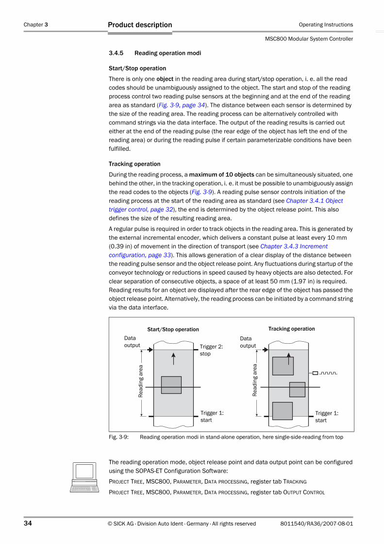
Start/Stop operation
There is only one object in the reading area during start/stop operation, i. e. all the read codes should be unambiguously assigned to the object. The start and stop of the reading process control two reading pulse sensors at the beginning and at the end of the reading area as standard (Fig. 3-9, page 34). The distance between each sensor is determined by the size of the reading area. The reading process can be alternatively controlled with command strings via the data interface. The output of the reading results is carried out either at the end of the reading pulse (the rear edge of the object has left the end of the reading area) or during the reading pulse if certain parameterizable conditions have been fulfilled.
Tracking operation
During the reading process, a maximum of 10 objects can be simultaneously situated, one behind the other, in the tracking operation, i. e. it must be possible to unambiguously assign the read codes to the objects (Fig. 3-9). A reading pulse sensor controls initiation of the reading process at the start of the reading area as standard (see Chapter 3.4.1 Object trigger control, page 32), the end is determined by the object release point. This also defines the size of the resulting reading area.
A regular pulse is required in order to track objects in the reading area. This is generated by the external incremental encoder, which delivers a constant pulse at least every 10 mm (0.39 in) of movement in the direction of transport (see Chapter 3.4.3 Increment configuration, page 33). This allows generation of a clear display of the distance between the reading pulse sensor and the object release point. Any fluctuations during startup of the conveyor technology or reductions in speed caused by heavy objects are also detected. For clear separation of consecutive objects, a space of at least 50 mm (1.97 in) is required. Reading results for an object are displayed after the rear edge of the object has passed the object release point. Alternatively, the reading process can be initiated by a command string via the data interface.
The reading operation mode, object release point and data output point can be configured using the SOPAS-ET Configuration Software:
PROJECT TREE, MSC800, PARAMETER, DATA PROCESSING, register tab TRACKING
PROJECT TREE, MSC800, PARAMETER, DATA PROCESSING, register tab OUTPUT CONTROL
Fig. 3-9: Reading operation modi in stand-alone operation, here single-side-reading from top
Start/Stop operation Tracking operation
Trigger 2:stop
Trigger 1:start
Trigger 1:start
Read
ing
area
Dataoutput
Dataoutput
Read
ing
area

Operating Instructions Chapter 3
MSC800
Product description
8011540/RA36/2007-08-01 © SICK AG · Division Auto Ident · Germany · All rights reserved 35
3.4.6 Data processing
Event-dependent evaluation conditions as well as filters and sorters can be configured using the SOPAS-ET Configuration Software:
PROJECT TREE, MSC800, PARAMETER, DATA PROCESSING, EVALUATION CONDITIONS
PROJECT TREE, MSC800, PARAMETER, DATA PROCESSING, FILTER/SORTER FOR OUTPUT
3.4.7 Output formats
The reading results (decoded codes) are output via selectable physical data interfaces. Two different output formats (telegrams) can be defined for this task. Additionally, an output format for unsuccessful decoding ("No Read") and an output format for the heartbeat can be defined.
The output formats can be configured using the SOPAS-ET Configuration Software:
PROJECT TREE, MSC800, PARAMETER, DATA PROCESSING, OUTPUT FORMAT
3.4.8 Network
The MSC800 assumes coordination of the 1D/2-D code sensors for multi-side reading. The sensors and the MSC800 are networked via the CAN bus.
The network parameters can be configured using the SOPAS-ET Configuration Software:
PROJECT TREE, MSC800, PARAMETER, NETWORK / INTERFACE / IOS, register tabs NETWORK OPTIONS and MASTER / SLAVE
3.4.9 Data interfaces
Numerous data interfaces are available at the logic controller of the MSC800.
Data interface Connection Function
Serial host interfaces
HOST 1, HOST 2
Preparation of the reading result with two output formats or in a customer-specific format/using a customer-specific protocol for further processing by the host processor
Serial auxiliary interfaces
AUX 1, AUX 2
Reading diagnosis and monitoring the host interfaces, preparation of the reading result with two output formats or in a customer-specific format/using a customer-specific protocol.Connection to the RDT400 tool.
Ethernet ETHERNET Host port:Preparation of the reading result with two output formats or in a customer-specific format/using a customer-specific protocol for further processing by the host processorAux port:Reading diagnosis and monitoring the host interfaces, preparation of the reading result with two output formats or in a customer-specific format/using a customer-specific protocol.Connection to the RDT400 tool.
Tab. 3-4: Data interface function

Chapter 3 Operating Instructions
MSC800 Modular System Controller
36 © SICK AG · Division Auto Ident · Germany · All rights reserved 8011540/RA36/2007-08-01
Product description
The data interfaces can be configured using the SOPAS-ET Configuration Software:
PROJECT TREE, MSC800, PARAMETER, NETWORK / INTERFACE / IOS, SERIAL
PROJECT TREE, MSC800, PARAMETER, NETWORK / INTERFACE / IOS, ETHERNET
PROJECT TREE, MSC800, PARAMETER, NETWORK / INTERFACE / IOS, CAN
PROJECT TREE, MSC800, PARAMETER, NETWORK / INTERFACE / IOS, PROFIBUS
3.4.10 Digital outputs
On certain events during the reading process (e. g. for unsuccessful decoding "No Read"), from each other independent switch signals can be generated at the 4 digital outputs and can be used to display the status of the reading result. Further on, the outputs can report the system status (e.g. ready for operation, exceeding of the temperature in the cabinet).
The digital outputs can be configured using the SOPAS-ET Configuration Software:
PROJECT TREE, MSC800, PARAMETER, NETWORK / INTERFACE / IOS, DIGITAL OUTPUTS, register tabs OUTPUT 1 to OUTPUT 4
3.4.11 Relay outputs
The MSC800 also provides 2 relay outputs (toogle switch). The outputs can be used with the same functions like the digital outputs.
The relay outputs can be configured using the SOPAS-ET Configuration Software:
PROJECT TREE, MSC800, PARAMETER, NETWORK / INTERFACE / IOS, DIGITAL OUTPUTS, register tabs RELAY 1 and RELAY 2
3.4.12 Digital inputs
The external sensor for the object trigger control (photoelectric reflex switch) and the incremental encoder can, e. g., be connected to the 10 digital inputs.
The digital inputs can be configured using the SOPAS-ET Configuration Software:
PROJECT TREE, MSC800, PARAMETER, NETWORK / INTERFACE / IOS, DIGITAL INPUTS, register tabs SENSOR 1 bis SENSOR 6
PROJECT TREE, MSC800, PARAMETER, NETWORK / INTERFACE / IOS, DIGITAL INPUTS, register tabs TRIGGER 1 bis TRIGGER 4
CAN bus CAN 1 (Out/In), CAN 2 (Out/In)
Networking of the MSC800 with one or several ICR890 Systems
PROFIBUS-DP PROFIBUS Preparation of the reading result for further processing by the host processor
Data interface Connection Function
Tab. 3-4: Data interface function

Operating Instructions Chapter 3
MSC800
Product description
8011540/RA36/2007-08-01 © SICK AG · Division Auto Ident · Germany · All rights reserved 37
3.5 Indicators and control elements
3.5.1 User interface
The MSC800 is configured application specifically using the SOPAS-ET Configuration Software (see Chapter 6.3.1 Overview of the configuration procedure, page 77). The software for this runs on a PC which has to be connected to one of the data interfaces ("AUX" RS 232, "ETHERNET" or "USB") of the MSC800.
As an alternative to the SOPAS-ET Configuration Software, command strings are available upon which the user interface of the SOPAS-ET Configuration Software is based (see Chapter 10.2 Configuring the ICR890 System with command strings, page 95).
In case of an error, startup and diagnosis can only be carried out via the SOPAS-ET Configuration Software. The MSC800 works fully automatically in normal operation. Further operating elements are not available at the MSC800.
Parameter set on the SD memory card
The configured parameter values are saved as a parameter set in the internal flash PROM of the MSC800 and on the SD memory card (SD 1) of the logic controller (cloning). If the logic controller needs replacing, the memory card allows convenient and rapid transfer of the parameter set to a new device (also see Chapter 7.3 Cleaning further optical effective surfaces, page 82).
Note To prevent data loss, the SD memory card should only be removed or inserted in a new device when the MSC800 is switched off.
The card is accessible from the left-hand side of the logic controller of the MSC800.
3.5.2 LED functions
The accessible LEDs of the MSC800 are located at the power supply modules, on the fuse module for the 24 V DC supply voltage (CLV490, VMS4xx/5xx, logic controller; only MSC800-1100, MSC800-2100 and MSC800-2300) and on the logic controller.
Tab. 3-5, page 38 lists the meaning of the LEDs.
Fig. 3-10: Position of the SD memory card for parameter set at the logic controller
Slot for SD memory card use
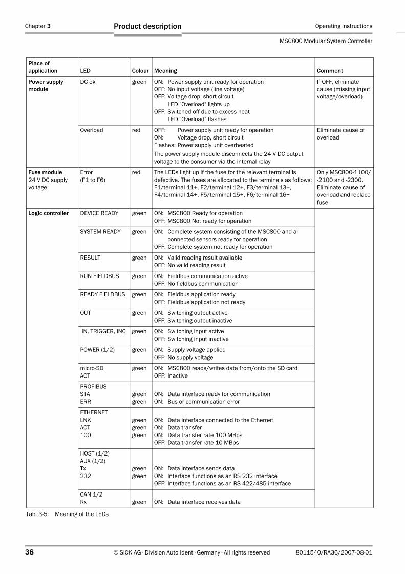
Chapter 3 Operating Instructions
MSC800 Modular System Controller
38 © SICK AG · Division Auto Ident · Germany · All rights reserved 8011540/RA36/2007-08-01
Product description
Place of application LED Colour Meaning Comment
Power supply module
DC ok green ON: Power supply unit ready for operationOFF: No input voltage (line voltage)OFF: Voltage drop, short circuit
LED "Overload" lights upOFF: Switched off due to excess heat
LED "Overload" flashes
If OFF, eliminate cause (missing input voltage/overload)
Overload red OFF: Power supply unit ready for operationON: Voltage drop, short circuitFlashes: Power supply unit overheatedThe power supply module disconnects the 24 V DC output voltage to the consumer via the internal relay
Eliminate cause of overload
Fuse module24 V DC supply voltage
Error(F1 to F6)
red The LEDs light up if the fuse for the relevant terminal is defective. The fuses are allocated to the terminals as follows:F1/terminal 11+, F2/terminal 12+, F3/terminal 13+,F4/terminal 14+, F5/terminal 15+, F6/terminal 16+
Only MSC800-1100/-2100 and -2300.Eliminate cause of overload and replace fuse
Logic controller DEVICE READY green ON: MSC800 Ready for operation OFF: MSC800 Not ready for operation
SYSTEM READY green ON: Complete system consisting of the MSC800 and allconnected sensors ready for operation
OFF: Complete system not ready for operation
RESULT green ON: Valid reading result availableOFF: No valid reading result
RUN FIELDBUS green ON: Fieldbus communication active OFF: No fieldbus communication
READY FIELDBUS green ON: Fieldbus application ready OFF: Fieldbus application not ready
OUT green ON: Switching output active OFF: Switching output inactive
IN, TRIGGER, INC green ON: Switching input active OFF: Switching input inactive
POWER (1/2) green ON: Supply voltage applied OFF: No supply voltage
micro-SDACT
green ON: MSC800 reads/writes data from/onto the SD card OFF: Inactive
PROFIBUSSTAERR
greengreen
ON: Data interface ready for communication ON: Bus or communication error
ETHERNET LNKACT100
greengreengreen
ON: Data interface connected to the Ethernet ON: Data transferON: Data transfer rate 100 MBps OFF: Data transfer rate 10 MBps
HOST (1/2)AUX (1/2)Tx232
greengreen
ON: Data interface sends data ON: Interface functions as an RS 232 interface OFF: Interface functions as an RS 422/485 interface
CAN 1/2Rx green ON: Data interface receives data
Tab. 3-5: Meaning of the LEDs
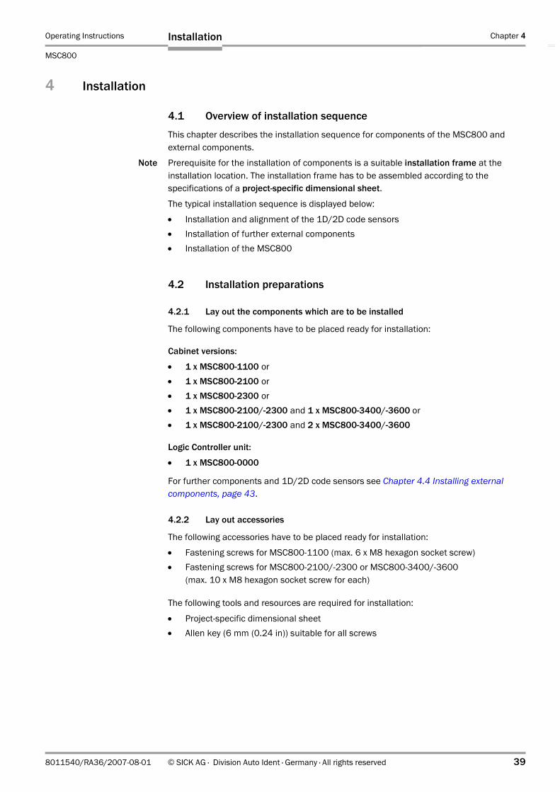
Operating Instructions Chapter 4
MSC800
Installation
8011540/RA36/2007-08-01 © SICK AG · Division Auto Ident · Germany · All rights reserved 39
4 Installation
4.1 Overview of installation sequence
This chapter describes the installation sequence for components of the MSC800 and external components.
Note Prerequisite for the installation of components is a suitable installation frame at the installation location. The installation frame has to be assembled according to the specifications of a project-specific dimensional sheet.
The typical installation sequence is displayed below:
• Installation and alignment of the 1D/2D code sensors• Installation of further external components• Installation of the MSC800
4.2 Installation preparations
4.2.1 Lay out the components which are to be installed
The following components have to be placed ready for installation:
Cabinet versions:
• 1 x MSC800-1100 or• 1 x MSC800-2100 or• 1 x MSC800-2300 or• 1 x MSC800-2100/-2300 and 1 x MSC800-3400/-3600 or• 1 x MSC800-2100/-2300 and 2 x MSC800-3400/-3600
Logic Controller unit:
• 1 x MSC800-0000
For further components and 1D/2D code sensors see Chapter 4.4 Installing external components, page 43.
4.2.2 Lay out accessories
The following accessories have to be placed ready for installation:
• Fastening screws for MSC800-1100 (max. 6 x M8 hexagon socket screw) • Fastening screws for MSC800-2100/-2300 or MSC800-3400/-3600
(max. 10 x M8 hexagon socket screw for each)
The following tools and resources are required for installation:
• Project-specific dimensional sheet• Allen key (6 mm (0.24 in)) suitable for all screws

Chapter 4 Operating Instructions
MSC800 Modular System Controller
40 © SICK AG · Division Auto Ident · Germany · All rights reserved 8011540/RA36/2007-08-01
Installation
4.2.3 Selecting the installation location
Dimensional sheet
The general installation location requirements are described in Chapter 3.2.1, page 28. The project-specific specifications (position of the components, distances, angles, etc.) are contained in a dimensional sheet and have to be adhered to when installing components.
Fig. 4-1: Example of a project-specific dimensional sheet for installation
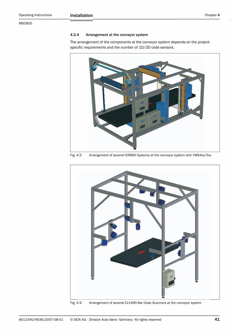
Operating Instructions Chapter 4
MSC800
Installation
8011540/RA36/2007-08-01 © SICK AG · Division Auto Ident · Germany · All rights reserved 41
4.2.4 Arrangement at the conveyor system
The arrangement of the components at the conveyor system depends on the project-specific requirements and the number of 1D/2D code sensors.
Fig. 4-2: Arrangement of several ICR890 Systems at the conveyor system with VMS4xx/5xx
Fig. 4-3: Arrangement of several CLV490 Bar Code Scanners at the conveyor system

Chapter 4 Operating Instructions
MSC800 Modular System Controller
42 © SICK AG · Division Auto Ident · Germany · All rights reserved 8011540/RA36/2007-08-01
Installation
4.3 Installation
The position of the MSC800 on the installation frame is specified project specifically on a dimensional sheet (Fig. 4-1, page 40). The specifications have to adhered to during installation, since the cable lengths correspond to the component positions.
4.3.1 Installing the cabinet versions of the MSC800
The MSC800 is attached directly to the installation frame according to the specifications in the project-specific dimensional sheet. The number of cabinets depends on the project-specific requirements. Select a position for the cabinets which allows simple cable installation and easy opening of the cabinets.
Note During installation of the MSC800-2100/-2300 and MSC800--3400/-3600 always ensure that the air inlet and air outlet opening are not covered.
Risk of injuries due to falling components!
The weight of the MSC800 is approx. 10 to 20 kg (22 to 44 lb) depending on the version.
Do not carry out installation work alone.
A second person should always secure components during installation.
1. Use at least 4 fastening screws to attach the cabinet of the MSC800-1100/MSC800-2100/-2300 to the installation frame close to the reading location.
2. Use at least 4 fastening screws per cabinet to attach the cabinets of additional MSC800-3400s/-3600s to the installation frame.
4.3.2 Installing the MSC800-0000 Logic Controller unit
Installations requirements:In order to ensure the safe operation of the MSC800-0000 in compliance with the regulati-ons, the following must be taken into account:
1. Install the device in a metal control cabinet housing.2. Carry out the installation and assemby of the device in compliance with the recognised
current state-of-the-art technoloy (e.g. connect a protective conductor for electrical safety).
3. Only use shielded cables for all data interfaces (serial, CAN, Ethernet) and for connec-ting the incremental encoder.
4. Connect the shield of the cables for the data interfaces and the incremental encoder to the control cabinet housing when entering the cabinet.
5. Commissing the entire device only after establishment of EC conformity.

Operating Instructions Chapter 4
MSC800
Installation
8011540/RA36/2007-08-01 © SICK AG · Division Auto Ident · Germany · All rights reserved 43
4.4 Installing external components
4.4.1 Installing the 1D/2D code sensors
The arrangement of the 1D/2D code sensors depends on the project-specific requirements and the number of sensors.
1. Install a unit consisting of an illumination and camera together with a deflection mirror to the installation frame for each ICR890 System.
2. Install the CLV490 Bar Code Scanner according to the specifications in the project-specific dimensional sheet.
For further information see the operating instructions "ICR890 High End CCD Camera System" (no. 8011325) and the operating instructions "CLV490 Bar Code Scanner" (no. 8009993).
4.4.2 External sensors for triggering
The reading pulse sensor (photoelectric reflex switch) is attached to the right-hand edge of the conveyor system according to the specifications in the project-specific dimensional sheet. The position of the photoelectric reflex switch is the reference point for the position of the other components (see Fig. 4-4). The photoelectric reflex switch has to be aligned as vertically as possible in the direction of transport.
Install the photoelectric reflex switch onto the conveyor system.
4.4.3 Installing the incremental encoder
The incremental encoder is attached directly to the conveyor system according to the specifications in the project-specific dimensional sheet. The position of the incremental encoder should be as close as possible to the reading location.
Install the incremental encoder to the reading location. Ensure that the friction wheel has direct and permanent contact with the conveyor surface and does not slip.
Fig. 4-4: Position of the external components
Reference point
Direction of transport
1D/2D code sensors
Incremental encoder(optional) VMS4xx/5xx
orMLG Light Grid
Reading pulse(start/stop)
Object release point
Reading area
Photoelectric reflex switch
Object distance

Chapter 4 Operating Instructions
MSC800 Modular System Controller
44 © SICK AG · Division Auto Ident · Germany · All rights reserved 8011540/RA36/2007-08-01
Installation
4.4.4 Installing the MLG Light Grid or VMS4xx/5xx
The MLG Light Grid or the VMS4xx/5xx is attached directly to the installation frame according to the specifications in the project-specific dimensional sheet. Select a position for the MLG Light Grid which ensures that a large area above the conveyor level is detected by the sensors of the MLG. The lower sensors should not be permanently covered by the conveyor system.
Install the MLG Light Grid or VMS4xx/5xx to the installation frame
For further information see the operating instructions "MLG Modular Light Grid" (No. 8009403) or "VMS410/VMS510 Volume Measuring System" (no. 8010592) or "VMS420/VMS520 Volume Measuring System" (no. 8010448).
4.5 Removing the system
Risk of injuries due to falling components!
The weight of the MSC800 is approx. 10 to 20 kg (22 to 44 lb) depending on the version.
Do not carry out removal work alone.
A second person should always secure components during removal.
Removal of the MSC800 is described in Chapter 7.6 Disposal, page 84. Removal of the individual components of the MSC800 is described in Chapter 7.3 Cleaning further optical effective surfaces, page 82.
Carry out environmentally friendly disposal after decommissioning according to Chapter 7.6 Disposal, page 84.

Operating Instructions Chapter 5
MSC800
Electrical installation
8011540/RA36/2007-08-01 © SICK AG · Division Auto Ident · Germany · All rights reserved 45
5 Electrical installation
5.1 Overview of installation sequence
Note Complete installation of the MSC800 (see chapter 4 „Installation“) is a prerequisite for electrical installation.
The following list provides an overview of a typical installation sequence:
• Connecting the ICR890 System and/or CLV490 to the supply voltage OUT• Connecting the ICR890 System and/or CLV490 to the MSC800 via the CAN bus• Connecting the MLG Light Grid (RS 485) or the VMS4xx/5xx (CAN bus)• Connecting the reading pulse sensor(s)• Connecting the incremental encoder• Optional: Wiring the switching outputs for system status indication• Connecting the host processor (RS 232, RS 422/485, Ethernet or PROFIBUS-DP)• Connecting a PC/laptop temporarily for startup/configuration
(RS 232, Ethernet or USB)• Connecting the line voltage IN
The actual installation work which has to be carried out depends on the respective system configuration with which the MSC800 is operated (see chapter 5.2 „Electrical installation of the MSC800“). Once electrical installation has been completed, the MSC800 is started up and configured (see chapter 6.1 „Overview of the startup procedure“).

Chapter 5 Operating Instructions
MSC800 Modular System Controller
46 © SICK AG · Division Auto Ident · Germany · All rights reserved 8011540/RA36/2007-08-01
Electrical installation
5.2 Electrical installation of the MSC800
The MSC800 with 1D/2D code sensors is used for single-side reading or for multi-side reading.
These possibilities of use are described in this chapter by means of a block diagram and a connection table. The terminals for the 24 V DC supply voltage and the connections at the logic controller of the MSC800 are described in chapter Chapter 5.3, page 47. Instructions on how to carry out the individual installation sequences are contained in Chapter 5.4, page 58.
Block diagram of the MSC800
Wiring of the MSC800
The following connections have to be established at the MSC800:
Fig. 5-1: Block diagram: Connection principle of an MSC800
MSC800
100 to 264 V AC/50 to 60 Hz
ICR890 System
GBIT 1/2 ETHERNET
Real-timeimage presentation
Special PC
OUT
PC/laptopConfiguration/Diagnosis(temporary)
AUX/ USB/ETHERNET
HOST/ ETHERNET/PROFIBUS-DP
TRIGGER
Reading resultHost processor
CAN
Reading pulsePhotoelectric reflex switch
Incremental encoder
HOST
VMS4xx/5xxCLV490
24 V DC supply voltage
Detection of object heights
MLG Light Grid
HOST/AUX
No. Connection at the MSC800
Function Connection to ... Cable to be used
1 Terminal block -X100
Supply voltage of the MSC800 Mains voltage 100 to 264 V AC/50 to 60 Hz
Cable provided by the client
2 Terminal blocks
Supply voltage for the ICR890, CLV490 and VMS4xx/5xx
ICR890 System (connection POWER IN)/corresponding wires of the CAN cable
(Included in ICR890 delivery)
3 CAN Communication with sensors External sensors (Included in ICR890 delivery)
4 TRIGGER Reading pulse trigger signals External reading pulse sensor (Included in ICR890 delivery)
5 HOST orETHERNET orPROFIBUS
Data output of the reading result Host processor (RS 232, RS 422/485 or Ethernet)
Cable provided by the client
6 OUT Indication of system status PLC (optional) Cable provided by the client
7 AUX orUSB orETHERNET
Configuration/Diagnosis Standard PC, temporarily Cable provided by the client
Tab. 5-1: MSC800: Overview of the connections which have to be established at the MSC800
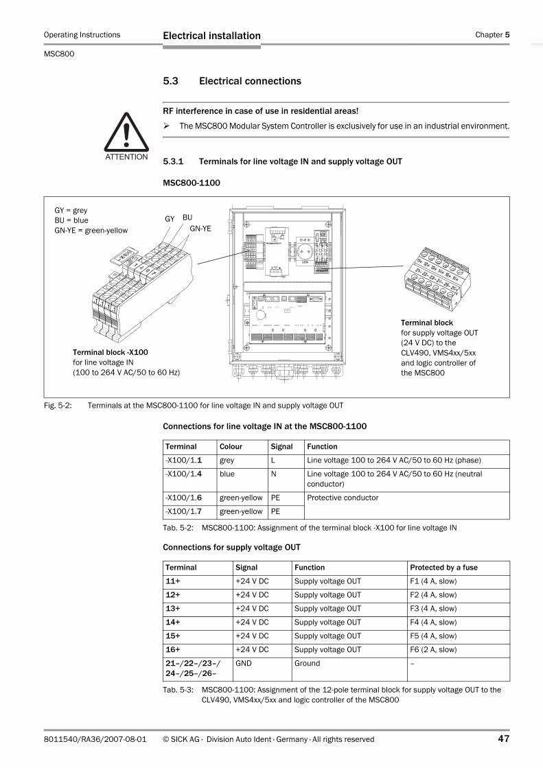
Operating Instructions Chapter 5
MSC800
Electrical installation
8011540/RA36/2007-08-01 © SICK AG · Division Auto Ident · Germany · All rights reserved 47
5.3 Electrical connections
RF interference in case of use in residential areas!
The MSC800 Modular System Controller is exclusively for use in an industrial environment.
5.3.1 Terminals for line voltage IN and supply voltage OUT
MSC800-1100
Connections for line voltage IN at the MSC800-1100-
Connections for supply voltage OUT -
Fig. 5-2: Terminals at the MSC800-1100 for line voltage IN and supply voltage OUT
Terminal block -X100 for line voltage IN(100 to 264 V AC/50 to 60 Hz)
Terminal block for supply voltage OUT (24 V DC) to the CLV490, VMS4xx/5xx and logic controller of the MSC800
GN-YEBUGY
GY = greyBU = blueGN-YE = green-yellow
Terminal Colour Signal Function
-X100/1.1 grey L Line voltage 100 to 264 V AC/50 to 60 Hz (phase)
-X100/1.4 blue N Line voltage 100 to 264 V AC/50 to 60 Hz (neutral conductor)
-X100/1.6 green-yellow PE Protective conductor
-X100/1.7 green-yellow PE
Tab. 5-2: MSC800-1100: Assignment of the terminal block -X100 for line voltage IN
Terminal Signal Function Protected by a fuse
11+ +24 V DC Supply voltage OUT F1 (4 A, slow)
12+ +24 V DC Supply voltage OUT F2 (4 A, slow)
13+ +24 V DC Supply voltage OUT F3 (4 A, slow)
14+ +24 V DC Supply voltage OUT F4 (4 A, slow)
15+ +24 V DC Supply voltage OUT F5 (4 A, slow)
16+ +24 V DC Supply voltage OUT F6 (2 A, slow)
21–/22–/23–/24–/25–/26–
GND Ground –
Tab. 5-3: MSC800-1100: Assignment of the 12-pole terminal block for supply voltage OUT to the CLV490, VMS4xx/5xx and logic controller of the MSC800

Chapter 5 Operating Instructions
MSC800 Modular System Controller
48 © SICK AG · Division Auto Ident · Germany · All rights reserved 8011540/RA36/2007-08-01
Electrical installation
MSC800-2100
Connections for line voltage IN at the MSC800-2100-
Connections for supply voltage OUT -
Fig. 5-3: Terminals at the MSC800-2100 for line voltage IN and supply voltage OUT
Terminal block -X100 for line voltage IN(100 to 264 V AC/50 to 60 Hz)
Terminal block for supply voltage OUT (24 V DC) to the CLV490, VMS4xx/5xx and logic controller of the MSC800
GN-YEBUGY
GY = greyBU = blueGN-YE = green-yellow
Terminal Colour Signal Function
-X100/1.1 grey L Line voltage 100 to 264 V AC/50 to 60 Hz (phase)
-X100/1.4 blue N Line voltage 100 to 264 V AC/50 to 60 Hz (neutral conductor)
-X100/1.6 green-yellow PE Protective conductor
-X100/1.7 green-yellow PE
Tab. 5-4: MSC800-2100: Assignment of the terminal block -X100 for line voltage IN
Terminal Signal Function Protected by a fuse
11+ +24 V DC Supply voltage OUT F1 (4 A, slow)
12+ +24 V DC Supply voltage OUT F2 (4 A, slow)
13+ +24 V DC Supply voltage OUT F3 (4 A, slow)
14+ +24 V DC Supply voltage OUT F4 (4 A, slow)
15+ +24 V DC Supply voltage OUT F5 (4 A, slow)
16+ +24 V DC Supply voltage OUT F6 (2 A, slow)
21–/22–/23–/24–/25–/26–
GND Ground –
Tab. 5-5: MSC800-2100: Assignment of the 12-pole terminal block for supply voltage OUT to the CLV490, VMS4xx/5xx and logic controller of the MSC800

Operating Instructions Chapter 5
MSC800
Electrical installation
8011540/RA36/2007-08-01 © SICK AG · Division Auto Ident · Germany · All rights reserved 49
MSC800-2300
Connections for line voltage IN at the MSC800-2300-
Connections for supply voltage OUT at the MSC800-2300 for the ICR890-
Fig. 5-4: Terminals at the MSC800-2300 for line voltage IN and supply voltage OUT
Terminal bock -X100 for line voltage IN(100 to 264 V AC/50 to 60 Hz)
Terminal block -X120 for supply voltage OUT (24 V DC) to the ICR890
GN-YEBUGY
GY = greyBU = blueGN-YE = green-yellow
Terminal block for supply voltage OUT (24 V DC) to the CLV490, VMS4xx/5xx and logic controller of the MSC800
Terminal Colour Signal Function
-X100/1.1 grey L Line voltage 100 to 264 V AC/50 to 60 Hz (phase)
-X100/1.4 blue N Line voltage 100 to 264 V AC/50 to 60 Hz (neutral conductor)-X100/1.5 blue N
-X100/1.6 green-yellow PE Protective conductor
-X100/1.7 green-yellow PE
Tab. 5-6: MSC800-2300: Assignment of the terminal block -X100 for line voltage IN
Terminal Signal Function
-X120/11 +24 V DC Supply voltage OUT 2 (power supply module 2)
-X120/12 GND Ground 2 (power supply module 2)
-X120/13 +24 V DC Supply voltage OUT 1 (power supply module 1)
-X120/14 GND Ground 1 (power supply module 1)
-X120/15 +24 V DC Supply voltage OUT 3 (power supply module 3)
-X120/16 GND Ground 3 (power supply module 3)
-X120/17 Shield Shielding
-X120/18 Shield
-X120/19 Shield
Tab. 5-7: MSC800-2300: Assignment of the terminal block for supply voltage OUT to the ICR890

Chapter 5 Operating Instructions
MSC800 Modular System Controller
50 © SICK AG · Division Auto Ident · Germany · All rights reserved 8011540/RA36/2007-08-01
Electrical installation
Connections for supply voltage OUT at the MSC800-2300 for the CLV490, VMS4xx/5xx and logic controller of the MSC800 -
Terminal Signal Function Protected by a fuse
11+ +24 V DC Supply voltage OUT 2 F1 (4 A, slow)
12+ +24 V DC Supply voltage OUT 2 F2 (4 A, slow)
13+ +24 V DC Supply voltage OUT 2 F3 (4 A, slow)
14+ +24 V DC Supply voltage OUT 2 F4 (4 A, slow)
15+ +24 V DC Supply voltage OUT 2 F5 (4 A, slow)
16+ +24 V DC Supply voltage OUT 2 F6 (2 A, slow)
21–/22–/23–/24–/25–/26–
GND Ground –
Tab. 5-8: MSC800-2300: Assignment of the 12-pole terminal block for supply voltage OUT 2 to the CLV490, VMS4xx/5xx and logic controller of the MSC800

Operating Instructions Chapter 5
MSC800
Electrical installation
8011540/RA36/2007-08-01 © SICK AG · Division Auto Ident · Germany · All rights reserved 51
MSC800-3400
Connections for line voltage IN at the MSC800-3400-
Connections for supply voltage OUT at the MSC800-3400 -
Fig. 5-5: Terminals at the MSC800-3400 for line voltage IN and supply voltage OUT
Terminal bock -X100 for line voltage IN(100 to 264 V AC/50 to 60 Hz)
Terminal block -X120 for supply voltage OUT (24 V DC) to the ICR890
GY = greyBU = blueGN-YE = green-yellow
GN-YE
BUGY
KLS = terminal set
KLS 1 KLS 2
Terminal Terminal Signal Function
-X100/1.1 grey L Line voltage 100 to 264 V AC/50 to 60 Hz (phase)*)
-X100/1.2 grey L
-X100/1.3 grey L
-X100/1.4 blue N Line voltage 100 to 264 V AC/50 to 60 Hz (neutral conductor)-X100/1.5 blue N
-X100/1.6 green-yellow PE Protective conductor
-X100/1.7 green-yellow PE*) An assignment with three different phases (three-phase current) is possible after removing the bridge between the grey
terminals
Tab. 5-9: MSC800-3400: Assignment of the terminal block -X100 for line voltage IN
Terminal set
Terminal Signal Function Protected by an automatic circuit breaker
KLS 1 -X120/11 +24 V DC Supply voltage OUT 1 (power supply module 1)
–F111
-X120/13 +24 V DC –F113
-X120/15 +24 V DC –F115
-X120/12 GND Ground 1 –
-X120/14 GND
-X120/16 GND
-X120/17 Shield Shielding –
-X120/18 Shield
-X120/19 Shield
Tab. 5-10: MSC800-3400: Assignment of the terminal block -X120, part 1 for supply voltage OUT to the ICR890 (system 1)

Chapter 5 Operating Instructions
MSC800 Modular System Controller
52 © SICK AG · Division Auto Ident · Germany · All rights reserved 8011540/RA36/2007-08-01
Electrical installation
-
-
Terminal set
Terminal Signal Function Protected by an automatic circuit breaker
KLS 2 -X120/21 +24 V DC Supply voltage OUT 2 (power supply module 2)
–F121
-X120/23 +24 V DC –F123
-X120/25 +24 V DC –F125
-X120/22 GND Ground 2 –
-X120/24 GND
-X120/26 GND
-X120/27 Shield Shielding –
-X120/28 Shield
-X120/29 Shield
Tab. 5-11: MSC800-3400: Assignment of the terminal block -X120, part 2 for supply voltage OUT to the ICR890 (system 2)
Terminal Signal Function Protected by a fuse
-X120/41 + Measuring point thermal circuit breaker 1 (red)1)
–
-X120/42 – Measuring point thermal circuit breaker 1 (red)1)
–
-X120/51 +24 V DC Supply voltage OUT 1 (power supply modules 1 and 2, test point in front of the line safety switch F111/113/115) at the thermal circuit breaker 2 (blue)/fans 1 and 2
F1 (4 A, slow)
-X120/52 GND Ground –1) Thermal circuit breaker, on the left in the MSC800-3400 (Fig. 3-5, Page 25), switch opens at TU = 57.5 °C (135.5 °F).
Overheating of the cabinet can be indicated by applying a quiescent current circuit (+24 V DC at terminal -X120/41; GND at terminal -X120/42) and a corresponding analysis, e. g. via the logic controller of an MSC800. It is also possible to serially connect the same thermal circuit breaker of similar MSC800 cabinets.
2) Thermal circuit breaker, on the right in the MSC800-3400 (Fig. 3-5, Page 25), switch closes at TU = 37.5 °C (99.5 °F) and switches the two fans on or off.
Tab. 5-12: MSC800-3400: Terminal assignment of terminal block -X120, part 3 for supply voltage OUT at the thermal circuit breaker/fan

Operating Instructions Chapter 5
MSC800
Electrical installation
8011540/RA36/2007-08-01 © SICK AG · Division Auto Ident · Germany · All rights reserved 53
MSC800-3600
Connections for line voltage IN at the MSC800-3600-
Connections for supply voltage OUT at the MSC800-3600 -
Fig. 5-6: Terminals at the MSC800-3600 for line voltage IN and supply voltage OUT
Terminal bock -X100 for line voltage IN(100 to 264 V AC/50 to 60 Hz)
Terminal block -X120 for supply voltage OUT (24 V DC)to the ICR890
GY = greyBU = blueGN-YE = green-yellow
GN-YE
BUGY
KLS 1 KLS 2KLS 3
KLS = terminal set
Terminal Terminal Signal Function
-X100/1.1 grey L Line voltage 100 to 264 V AC/50 to 60 Hz (phase)*)
-X100/1.2 grey L
-X100/1.3 grey L
-X100/1.4 blue N Line voltage 100 to 264 V AC/50 to 60 Hz (neutral conductor)-X100/1.5 blue N
-X100/1.6 green-yellow PE Protective conductor
-X100/1.7 green-yellow PE*) An assignment with three different phases (three-phase current) is possible after removing the bridge between the grey
terminals
Tab. 5-13: MSC800-3600: Assignment of the terminal block -X100 for line voltage IN
Terminal set
Terminal Signal Function Protected by an automatic circuit breaker
KLS 1 -X120/11 +24 V DC Supply voltage OUT 1 (power supply modules 1 and 2)
–F111
-X120/13 +24 V DC –F113
-X120/15 +24 V DC –F115
-X120/12 GND Ground 1 –
-X120/14 GND
-X120/16 GND
-X120/17 Shield Shielding –
-X120/18 Shield
-X120/19 Shield
Tab. 5-14: MSC800-3600: Assignment of the terminal block -X120, part 1 for supply voltage OUT to the ICR890 (system 1)

Chapter 5 Operating Instructions
MSC800 Modular System Controller
54 © SICK AG · Division Auto Ident · Germany · All rights reserved 8011540/RA36/2007-08-01
Electrical installation
-
-
-
Terminal set
Terminal Signal Function Protected by an automatic circuit breaker
KLS 2 -X120/21 +24 V DC Supply voltage OUT 2 (power supply modules 3 and 4)
–F121
-X120/23 +24 V DC –F123
-X120/25 +24 V DC –F125
-X120/22 GND Ground 2 –
-X120/24 GND
-X120/26 GND
-X120/27 Shield Shielding –
-X120/28 Shield
-X120/29 Shield
Tab. 5-15: MSC800-3600: Assignment of the terminal block -X120, part 2 for supply voltage OUT to the ICR890 (system 2)
Terminal set
Terminal Signal Function Protected by an automatic circuit breaker
KLS 3 -X120/31 +24 V DC Supply voltage OUT 3 (power supply modules 5 and 6)
–F131
-X120/33 +24 V DC –F133
-X120/35 +24 V DC –F135
-X120/32 GND Ground 3 –
-X120/34 GND
-X120/36 GND
-X120/37 Shield Shielding –
-X120/38 Shield
-X120/39 Shield
Tab. 5-16: MSC800-3600: Assignment of the terminal block -X120, part 3 for supply voltage OUT to the ICR890 (system 3)
Terminal Signal Function Protected by a fuse
-X120/41 + Measuring point thermal circuit breaker 1 (red)1)
–
-X120/42 – Measuring point thermal circuit breaker 1 (red)1)
–
-X120/51 +24 V DC Supply voltage OUT 1 (power supply modules 1 and 2, test point in front of the line safety switch F111/113/115) at the thermal circuit breaker 2 (blue)/fans 1 and 2
F1 (4 A, slow)
-X120/52 GND Ground –1) Thermal circuit breaker, on the left in the MSC800-3600 (Fig. 3-6, Page 26), switch opens at TU = 57.5 °C (135.5 °F).
Overheating of the cabinet can be indicated by applying a quiescent current circuit (+24 V DC at terminal -X120/41; GND at terminal -X120/42) and a corresponding analysis, e. g. via the logic controller of an MSC800. It is also possible to serially connect the same thermal circuit breaker of similar MSC800 cabinets.
2) Thermal circuit breaker, on the right in the MSC800-3600 (Fig. 3-6, Page 26), switch closes at TU = 37.5 °C (99.5 °F) and switches the two fans on or off.
Tab. 5-17: MSC800-3600: Terminal assignment of terminal block -X120, part 4 for supply voltage OUT at the thermal circuit breaker/fan

Operating Instructions Chapter 5
MSC800
Electrical installation
8011540/RA36/2007-08-01 © SICK AG · Division Auto Ident · Germany · All rights reserved 55
5.3.2 Electrical connections at the MSC800-0000 logic controller (overview)
The following interfaces are realized via the logic controller connections:-
Fig. 5-7: MSC800-0000 logic controller in the cabinet of the MSC800-1100/-2100/-2300: Position of the electrical connections
ID Connection Design Number of poles Function
X15 PROFIBUS D-Sub 9, socket Main data interface
X14 USB 2 USB 4, socket Auxiliary data interface (only for SICK Service)
X13 ETHERNET 3 RJ-45 8, socket Auxiliary data interface
X12 ETHERNET 2 RJ-45 8, socket Auxiliary data interface
X11 USB 1 USB 4, socket Auxiliary data interface
X10 ETHERNET 1 RJ-45 8, socket Main data interface
X9 AUX (1/2) Block 10, terminals Auxiliary data interface (RS 232, RS 422/485)
X9 INT Block 4, terminals (only for SICK Service)
X8 AUX 1 D-Sub 9, plug Auxiliary data interface (RS 232)
X7 OUT Block 8, terminals 4 digital switching outputs (system status)
X7 OUT Block 6, terminals 2 relay outputs (system status)
X6 IN Block 12, terminals 6 digital switching inputs
X5 TRIGGER Block 12, terminals 4 digital switching inputs (reading pulse)
X4 INC Block 12, terminals 4 digital switching inputs (incremental encoder)
X3 HOST (1/2) Block 14, terminals Main data interface (RS 232, RS 422/485)
X2 CAN 2 Block 6, terminals Input/Output CAN SENSOR network 2
X2 CAN 1 Block 6, terminals Input/Output CAN SENSOR network 1
X1 POWER (1/2) Block 8, terminals Input 24 V DC supply voltage (from the power supply module)
Tab. 5-18: MSC800-0000: Function of the electrical connections (overview)
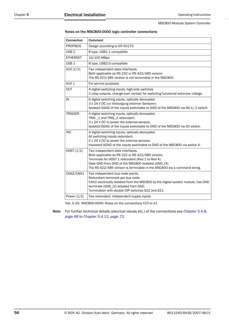
Chapter 5 Operating Instructions
MSC800 Modular System Controller
56 © SICK AG · Division Auto Ident · Germany · All rights reserved 8011540/RA36/2007-08-01
Electrical installation
Notes on the MSC800-0000 logic controller connections
Note For further technical details (elecrical values etc.) of the connections see Chapter 5.4.8, page 66 to Chapter 5.4.12, page 72.
Connection Comment
PROFIBUS Design according to EN 50170
USB 2 B type, USB1.1 compatible
ETHERNET 10/100 MBps
USB 1 B type, USB2.0 compatible
AUX (1/2) Two independent data interfaces.Both applicable as RS 232 or RS 422/485 version.The RS 422/485 version is not terminable in the MSC800.
AUX 1 For service purposes
OUT 4 digital switching inputs, high-side switches2 relay outputs, change-over contact for switching functional extra-low voltage
IN 6 digital switching inputs, optically decoupled. 3 x 24 V DC zur Versorgung externer Sensoren.Isolated SGND of the inputs switchable to GND of the MSC800 via S6-1/-2 switch.
TRIGGER 4 digital switching inputs, optically decoupled.TRIG _1 and TRIG_2 redundant.3 x 24 V DC to power the external sensors.Isolated SGND of the inputs switchable to GND of the MSC800 via S5 switch.
INC 4 digital switching inputs, optically decoupled. All switching inputs redundant.2 x 24 V DC to power the external sensors.Insolated SGND of the inputs switchable to GND of the MSC800 via switch 4.
HOST (1/2) Two independent data interfaces.Both applicable as RS 232 or RS 422/485 version.Terminals for HOST 1 redundant (Red 1 to Red 4).Data GND from GND of the MSC800 isolated (GND_I3).The RS 422/485 verison is terminable in the MSC800 via a command string.
CAN2/CAN1 Two independent bus node points.Redundant terminals per bus node.CAN2 electrically isolated from the MSC800 by the digital isolator module, has GND terminals (GND_I2) isolated from GND.Termination with double DIP switches S22 and S21.
Power (1/2) Two redundant, independent supply inputs
Tab. 5-19: MSC800-0000: Notes on the connections X15 to X1
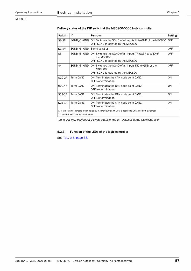
Operating Instructions Chapter 5
MSC800
Electrical installation
8011540/RA36/2007-08-01 © SICK AG · Division Auto Ident · Germany · All rights reserved 57
Delivery status of the DIP switch at the MSC800-0000 logic controller
5.3.3 Function of the LEDs of the logic controller
See Tab. 3-5, page 38.
Switch ID Function Setting
S6-21) SGND_6 - GND ON: Switches the SGND of all inputs IN to GND of the MSC800OFF: SGND is isolated by the MSC800
OFF
S6-11) SGND_6 - GND Same as S6-2 OFF
S5 SGND_5 - GND ON: Switches the SGND of all inputs TRIGGER to GND of the MSC800OFF: SGND is isolated by the MSC800
OFF
S4 SGND_5 - GND ON: Switches the SGND of all inputs INC to GND of the MSC800OFF: SGND is isolated by the MSC800
OFF
S22-22) Term CAN2 ON: Terminates the CAN node point CAN2OFF No termination
ON
S22-12) Term CAN2 ON: Terminates the CAN node point CAN2OFF No termination
ON
S21-22) Term CAN1 ON: Terminates the CAN node point CAN1OFF No termination
ON
S21-12) Term CAN1 ON: Terminates the CAN node point CAN1OFF No termination
ON
1) If the external sensors are supplied by the MSC800 and SGND is applied to GND, use both switches! 2) Use both switches for termination
Tab. 5-20: MSC800-0000: Delivery status of the DIP switches at the logic controller

Chapter 5 Operating Instructions
MSC800 Modular System Controller
58 © SICK AG · Division Auto Ident · Germany · All rights reserved 8011540/RA36/2007-08-01
Electrical installation
5.4 Performing electrical installation
Risk of injuries due to electrical current!
The MSC800 is connected to the power supply (100 to 264 V AC/50 to 60 Hz).
Observe current safety regulations when working with electrical equipment.
Make sure the equipment has been deenergized before performing any installation work.
Risk of injuries due to electrical current!
The applied line voltage (100 to 264 V AC/50 to 60 Hz) is protected by a 1-pole line safety switch (phase). If the connection of the phase and the neutral conductor to the terminal block -X120 has been interchanged, there is still a danger of death if you come into contact with parts even after switching off the input current circuit via the line safety switch -F12.
Carefully carry out connection of the line voltage at the terminal block -X100.
Check correct connection of the line voltage prior to switching on via the mains switch provided by the client.
Note To ensure secure fastening of the connected cables and adherence to the enclosure rating IP 54/IP 65, the lock nuts for strain relief at the cabinet of the MSC800 have to be tightened.
5.4.1 Wire-cross sections
Wire all connections provided by the client using shielded copper wires!
Pay attention to the required wire cross sections:
– Switching inputs/outputs: At least 0.25 mm2 (24 AWG)– Data interfaces: At least 0.22 mm2 (24 AWG)– Supply voltage: The supply line to the MSC800 has to be at least 2.5 m (8.2 ft) as
from a wire-cross section of 4 mm2 (11 AWG).
Lay all the cables in such a manner that persons cannot trip over them and that the cables are protected against damage.
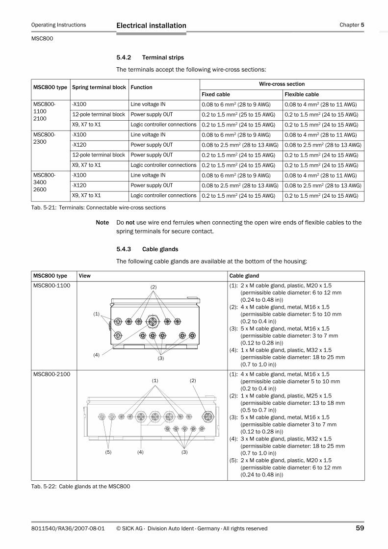
Operating Instructions Chapter 5
MSC800
Electrical installation
8011540/RA36/2007-08-01 © SICK AG · Division Auto Ident · Germany · All rights reserved 59
5.4.2 Terminal strips
The terminals accept the following wire-cross sections:
Note Do not use wire end ferrules when connecting the open wire ends of flexible cables to the spring terminals for secure contact.
5.4.3 Cable glands
The following cable glands are available at the bottom of the housing:
MSC800 type Spring terminal block Function Wire-cross section
Fixed cable Flexible cable
MSC800-11002100
-X100 Line voltage IN 0.08 to 6 mm2 (28 to 9 AWG) 0.08 to 4 mm2 (28 to 11 AWG)
12-pole terminal block Power supply OUT 0.2 to 1.5 mm2 (25 to 15 AWG) 0.2 to 1.5 mm2 (24 to 15 AWG)
X9, X7 to X1 Logic controller connections 0.2 to 1.5 mm2 (24 to 15 AWG) 0.2 to 1.5 mm2 (24 to 15 AWG)
MSC800-2300
-X100 Line voltage IN 0.08 to 6 mm2 (28 to 9 AWG) 0.08 to 4 mm2 (28 to 11 AWG)
-X120 Power supply OUT 0.08 to 2.5 mm2 (28 to 13 AWG) 0.08 to 2.5 mm2 (28 to 13 AWG)
12-pole terminal block Power supply OUT 0.2 to 1.5 mm2 (24 to 15 AWG) 0.2 to 1.5 mm2 (24 to 15 AWG)
X9, X7 to X1 Logic controller connections 0.2 to 1.5 mm2 (24 to 15 AWG) 0.2 to 1.5 mm2 (24 to 15 AWG)
MSC800-34002600
-X100 Line voltage IN 0.08 to 6 mm2 (28 to 9 AWG) 0.08 to 4 mm2 (28 to 11 AWG)
-X120 Power supply OUT 0.08 to 2.5 mm2 (28 to 13 AWG) 0.08 to 2.5 mm2 (28 to 13 AWG)
X9, X7 to X1 Logic controller connections 0.2 to 1.5 mm2 (24 to 15 AWG) 0.2 to 1.5 mm2 (24 to 15 AWG)
Tab. 5-21: Terminals: Connectable wire-cross sections
MSC800 type View Cable gland
MSC800-1100 (1): 2 x M cable gland, plastic, M20 x 1.5 (permissible cable diameter: 6 to 12 mm (0.24 to 0.48 in))
(2): 4 x M cable gland, metal, M16 x 1.5 (permissible cable diameter: 5 to 10 mm(0.2 to 0.4 in))
(3): 5 x M cable gland, metal, M16 x 1.5 (permissible cable diameter: 3 to 7 mm(0.12 to 0.28 in))
(4): 1 x M cable gland, plastic, M32 x 1.5 (permissible cable diameter: 18 to 25 mm(0.7 to 1.0 in))
MSC800-2100 (1): 4 x M cable gland, metal, M16 x 1.5 (permissible cable diameter 5 to 10 mm(0.2 to 0.4 in))
(2): 1 x M cable gland, plastic, M25 x 1.5 (permissible cable diameter: 13 to 18 mm(0.5 to 0.7 in))
(3): 5 x M cable gland, metal, M16 x 1.5 (permissible cable diameter 3 to 7 mm(0.12 to 0.28 in))
(4): 3 x M cable gland, plastic, M32 x 1.5 (permissible cable diameter: 18 to 25 mm(0.7 to 1.0 in))
(5): 2 x M cable gland, plastic, M20 x 1.5 (permissible cable diameter: 6 to 12 mm(0.24 to 0.48 in))
Tab. 5-22: Cable glands at the MSC800
(1)
(2)
(3)(4)
(3)(5)
(1)
(4)
(2)
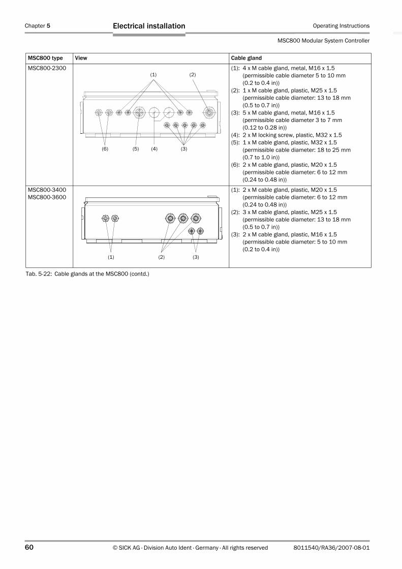
Chapter 5 Operating Instructions
MSC800 Modular System Controller
60 © SICK AG · Division Auto Ident · Germany · All rights reserved 8011540/RA36/2007-08-01
Electrical installation
MSC800-2300 (1): 4 x M cable gland, metal, M16 x 1.5 (permissible cable diameter 5 to 10 mm(0.2 to 0.4 in))
(2): 1 x M cable gland, plastic, M25 x 1.5 (permissible cable diameter: 13 to 18 mm(0.5 to 0.7 in))
(3): 5 x M cable gland, metal, M16 x 1.5 (permissible cable diameter 3 to 7 mm(0.12 to 0.28 in))
(4): 2 x M locking screw, plastic, M32 x 1.5(5): 1 x M cable gland, plastic, M32 x 1.5
(permissible cable diameter: 18 to 25 mm(0.7 to 1.0 in))
(6): 2 x M cable gland, plastic, M20 x 1.5 (permissible cable diameter: 6 to 12 mm(0.24 to 0.48 in))
MSC800-3400MSC800-3600
(1): 2 x M cable gland, plastic, M20 x 1.5 (permissible cable diameter: 6 to 12 mm(0.24 to 0.48 in))
(2): 3 x M cable gland, plastic, M25 x 1.5 (permissible cable diameter: 13 to 18 mm(0.5 to 0.7 in))
(3): 2 x M cable gland, plastic, M16 x 1.5 (permissible cable diameter: 5 to 10 mm(0.2 to 0.4 in))
MSC800 type View Cable gland
Tab. 5-22: Cable glands at the MSC800 (contd.)
(3)(6)
(1)
(5) (4)
(2)
(1) (2) (3)
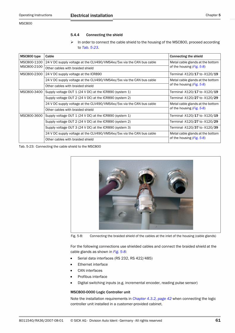
Operating Instructions Chapter 5
MSC800
Electrical installation
8011540/RA36/2007-08-01 © SICK AG · Division Auto Ident · Germany · All rights reserved 61
5.4.4 Connecting the shield
In order to connect the cable shield to the housing of the MSC800, proceed according to Tab. 5-23.
For the following connections use shielded cables and connect the braided shield at the cable glands as shown in Fig. 5-8:
• Serial data interfaces (RS 232, RS 422/485)• Ethernet interface• CAN interfaces• Profibus interface• Digital switching inputs (e.g. incremental encoder, reading pulse sensor)
MSC800-0000 Logic Controller unit
Note the installation requirements in Chapter 4.3.2, page 42 when connecting the logic controller unit installed in a customer-provided cabinet.
MSC800 type Cable Connecting the shield
MSC800-1100MSC800-2100
24 V DC supply voltage at the CLV490/VMS4xx/5xx via the CAN bus cable Metal cable glands at the bottom of the housing (Fig. 5-8) Other cables with braided shield
MSC800-2300 24 V DC supply voltage at the ICR890 Terminal -X120/17 to -X120/19
24 V DC supply voltage at the CLV490/VMS4xx/5xx via the CAN bus cable Metal cable glands at the bottom of the housing (Fig. 5-8)Other cables with braided shield
MSC800-3400 Supply voltage OUT 1 (24 V DC) at the ICR890 (system 1) Terminal -X120/17 to -X120/19
Supply voltage OUT 2 (24 V DC) at the ICR890 (system 2) Terminal -X120/27 to -X120/29
24 V DC supply voltage at the CLV490/VMS4xx/5xx via the CAN bus cable Metal cable glands at the bottom of the housing (Fig. 5-8)Other cables with braided shield
MSC800-3600 Supply voltage OUT 1 (24 V DC) at the ICR890 (system 1) Terminal -X120/17 to -X120/19
Supply voltage OUT 2 (24 V DC) at the ICR890 (system 2) Terminal -X120/27 to -X120/29
Supply voltage OUT 3 (24 V DC) at the ICR890 (system 3) Terminal -X120/37 to -X120/39
24 V DC supply voltage at the CLV490/VMS4xx/5xx via the CAN bus cable Metal cable glands at the bottom of the housing (Fig. 5-8)Other cables with braided shield
Tab. 5-23: Connecting the cable shield to the MSC800
Fig. 5-8: Connecting the braided shield of the cables at the inlet of the housing (cable glands)
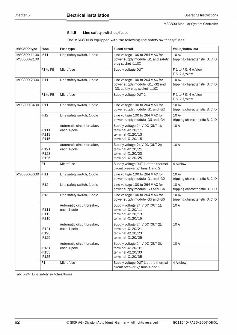
Chapter 5 Operating Instructions
MSC800 Modular System Controller
62 © SICK AG · Division Auto Ident · Germany · All rights reserved 8011540/RA36/2007-08-01
Electrical installation
5.4.5 Line safety switches/fuses
The MSC800 is equipped with the following line safety switches/fuses:
MSC800 type Fuse Fuse type Fused circuit Value/behaviour
MSC800-1100MSC800-2100
-F11 Line safety switch, 1-pole Line voltage 100 to 264 V AC for power supply module -G1 and safety plug socket -110X
10 A/tripping characteristic B, C, D
F1 to F6 Microfuse Supply voltage OUT F 1 to F 5: 4 A/slowF 6: 2 A/slow
MSC800-2300 -F11 Line safety switch, 1-pole Line voltage 100 to 264 V AC for power supply module -G1, -G2 and -G3, safety plug socket -110X
10 A/tripping characteristic B, C, D
F1 to F6 Microfuse Supply voltage OUT 2 F 1 to F 5: 4 A/slowF 6: 2 A/slow
MSC800-3400 -F11 Line safety switch, 1-pole Line voltage 100 to 264 V AC for power supply module -G1 and -G2
10 A/tripping characteristic B, C, D
-F12 Line safety switch, 1-pole Line voltage 100 to 264 V AC for power supply module -G3 and -G4
10 A/tripping characteristic B, C, D
-F111-F113-F115
Automatic circuit breaker, each 1-pole
Supply voltage 24 V DC (OUT 1); terminal -X120/11terminal -X120/13terminal -X120/15
10 A
-F121-F123-F125
Automatic circuit breaker, each 1-pole
Supply voltage 24 V DC (OUT 2); terminal -X120/21terminal -X120/23terminal -X120/25
10 A
F1 Microfuse Supply voltage OUT 1 at the thermal circuit breaker 2/ fans 1 and 2
4 A/slow
MSC800-3600 -F11 Line safety switch, 1-pole Line voltage 100 to 264 V AC for power supply module -G1 and -G2
10 A/tripping characteristic B, C, D
-F12 Line safety switch, 1-pole Line voltage 100 to 264 V AC for power supply module -G3 and -G4
10 A/tripping characteristic B, C, D
-F13 Line safety switch, 1-pole Line voltage 100 to 264 V AC for power supply module -G5 and -G6
10 A/tripping characteristic B, C, D
-F111-F113-F115
Automatic circuit breaker, each 1-pole
Supply voltage 24 V DC (OUT 1); terminal -X120/11terminal -X120/13terminal -X120/15
10 A
-F121-F123-F125
Automatic circuit breaker, each 1-pole
Supply voltage 24 V DC (OUT 2); terminal -X120/21terminal -X120/23terminal -X120/25
10 A
-F131-F133-F135
Automatic circuit breaker, each 1-pole
Supply voltage 24 V DC (OUT 3); terminal -X120/31terminal -X120/33terminal -X120/35
10 A
F1 Microfuse Supply voltage OUT 1 at the thermal circuit breaker 2/ fans 1 and 2
4 A/slow
Tab. 5-24: Line safety switches/fuses

Operating Instructions Chapter 5
MSC800
Electrical installation
8011540/RA36/2007-08-01 © SICK AG · Division Auto Ident · Germany · All rights reserved 63
5.4.6 24 V DC supply voltage for the ICR890 Systems
Supply voltage requirements
The typical power consumption of an ICR890 System is 425 W. The required power per system is supplied in the MSC800-2300 by three power supply modules, in the MSC800-3400 by two modules and in the MSC800-2600 by three pairs of power supply modules.
Tab. 5-25 displays the number of ICR890 Systems which can be operated per MSC800.
Note The wire-cross section for the power supply of the ICR890 System has to be at least 4 mm2 (11 AWG). To ensure protection against short circuit/overload of the supply line, the cable has to be protected according to the wire-cross sections used (as for the MSC800). The valid standards must be observed.
Connecting the supply voltage for the ICR890 Systems
1. Ensure that the line voltage (external supply voltage) to the MSC800 is switched off.2. Plug and fix the 8-pole Harting HanQ8 socket of the supply voltage line no. 2032398 at
the ICD890 Camera into the 8-pole Harting HanQ8 connector POWER IN for each system.
3. Connect the free cable end(s) to the terminal block for the ICR890 supply voltage of the MSC800-2300 (see Tab. 5-26), MSC800-3400 (see Tab. 5-27, page 64) or the MSC800-3600 (see Tab. 5-28, page 65).
Note The supply voltage remains switched off during the subsequent installation work!
MSC800 version Number of ICR890 Systems
MSC800-1100/-2100 –
MSC800-2300 1
MSC800-3400 2
MSC800-3600 3
Tab. 5-25: Number of ICR890 Systems per MSC800
Terminal Signal Wire colour (numbers printed on wires)
-X120/11 +24 V DC (ICD890 Camera) Wire 1: black
-X120/12 GND (ICD890 Camera) Wire 2: black
-X120/13 +24 V DC (ICI890_1#1 Illumination) Wire 3: black
-X120/14 GND (ICI890_1#1 Illumination) Wire 4: black
-X120/15 +24 V DC (ICI890_1#2 Illumination) Wire 5: black
-X120/16 GND (ICI890_1#2 Illumination) Wire 6: black
-X120/17 PE green-yellow
Tab. 5-26: MSC800-2300: Connecting the supply voltage cable for an ICR890 System
1 x cable no. 2039398
Terminal block -X120

Chapter 5 Operating Instructions
MSC800 Modular System Controller
64 © SICK AG · Division Auto Ident · Germany · All rights reserved 8011540/RA36/2007-08-01
Electrical installation
System/Terminal set Terminal Signal
Wire colour (numbers printed on wires)
System 1KLS1
-X120/11 +24 V DC (ICD890 Camera) Wire 1: black
-X120/12 GND (ICD890 Camera) Wire 2: black
-X120/13 +24 V DC (ICI890_1#1 Illumination) Wire 3: black
-X120/14 GND (ICI890_1#1 Illumination) Wire 4: black
-X120/15 +24 V DC (ICI890_1#2 Illumination) Wire 5: black
-X120/16 GND (ICI890_1#2 Illumination) Wire 6: black
-X120/17 PE green-yellow
System 2KLS2
-X120/21 +24 V DC (ICD890 Camera) Wire 1: black
-X120/22 GND (ICD890 Camera) Wire 2: black
-X120/23 +24 V DC (ICI890_2#1 Illumination) Wire 3: black
-X120/24 GND (ICI890_2#1 Illumination) Wire 4: black
-X120/25 +24 V CD (ICI890_2#2 Illumination) Wire 5: black
-X120/26 GND (ICI890_2#2 Illumination) Wire 6: black
-X120/27 PE green-yellow
Tab. 5-27: MSC800-3400: Connecting the supply voltage cables for two ICR890 Systems
2 x cable no. 2039398
Terminal block -X120 KLS = terminal set
KLS 1 KLS 2

Operating Instructions Chapter 5
MSC800
Electrical installation
8011540/RA36/2007-08-01 © SICK AG · Division Auto Ident · Germany · All rights reserved 65
System/Terminal set Terminal Signal
Wire colour (numbers printed on wires)
System 1KLS1
-X120/11 +24 V DC (ICD890 Camera) Wire 1: black
-X120/12 GND (ICD890 Camera) Wire 2: black
-X120/13 +24 V DC (ICI890_1 Illumination) Wire 3: black
-X120/14 GND (ICI890_1 Illumination) Wire 4: black
-X120/15 +24 V DC (ICI890_2 Illumination) Wire 5: black
-X120/16 GND (ICI890_2 Illumination) Wire 6: black
-X120/17 PE green-yellow
System 2KLS2
-X120/21 +24 V DC (ICD890 Camera) Wire 1: black
-X120/22 GND (ICD890 Camera) Wire 2: black
-X120/23 +24 V DC (ICI890_1 Illumination) Wire 3: black
-X120/24 GND (ICI890_1 Illumination) Wire 4: black
-X120/25 +24 V CD (ICI890_2 Illumination) Wire 5: black
-X120/26 GND (ICI890_2 Illumination) Wire 6: black
-X120/27 PE green-yellow
System 3KLS3
-X120/31 +24 V DC (ICD890 Camera) Wire 1: black
-X120/32 GND (ICD890 Camera) Wire 2: black
-X120/33 +24 V DC (ICI890_1 Illumination) Wire 3: black
-X120/34 GND (ICI890_1 Illumination) Wire 4: black
-X120/35 +24 V DC (ICI890_2 Illumination) Wire 5: black
-X120/36 GND (ICI890_2 Illumination) Wire 6: black
-X120/37 PE green-yellow
Tab. 5-28: MSC800-3600: Connecting the supply voltage cables for three ICR890 Systems
KLS 1 KLS 2KLS 3
3 x cable no. 2039398
Terminal block -X120 KLS = terminal set

Chapter 5 Operating Instructions
MSC800 Modular System Controller
66 © SICK AG · Division Auto Ident · Germany · All rights reserved 8011540/RA36/2007-08-01
Electrical installation
5.4.7 24 V DC supply voltage for CLV490 and VMS4xx/5xx
Supply voltage requirements
The typical power consumption of a CLV490 is 18 W. The required power for max. 14 CLV490s and a VMS4xx/5xx is supplied by the power supply module -G1 in the MSC800-1100/-2100 and by the power supply module -G2 in the MSC800-2300.
The power is supplied via the respective wires of the CAN cable which are connected directly to the terminals for the supply voltage.
Connecting the supply voltage for the CLV490 and the VMS4xx/5xx
1. Ensure that the line voltage (external supply voltage) to the MSC800 is switched off.2. Connect the CAN cable to the CLV490 or the VMS4xx/5xx.3. Connect the free cable ends for the supply voltage at the 12-pole terminal block for the
supply voltage CLV490 and VMS4xx/5xx of the MSC800-1100 or the MSC800-2300 (see Tab. 5-3, page 47 or Tab. 5-8, page 50).
5.4.8 HOST/AUX data interfaces of the logic controller
General conditions of the HOST and AUX data interfaces
Both the HOST data interface (main data interface) as well as the AUX data interface (auxiliary data interface) of the MSC800 can be operated as RS 232 version or as RS 422/485 version or be rerouted to the Ethernet interface. Tab. 5-29 shows the recommended maximum cable lengths, depending on the interface version and the data transfer rate.
Recommendation Use shielded data cables (twisted pair).
To prevent interference, do not lay data cables parallel to power supply cables and motor lines over a longer distance, e. g. in cable ducts.
Wiring the HOST/AUX data interface of the logic controller
Damage to the interface modules!
Incorrect wiring of the HOST/AUX data interfaces can damage electronic components in the MSC800.
Wire the data interfaces correctly according to Fig. 5-9.
Check the wiring carefully before switching on the MSC800.
Connect the data interfaces to the host/PC paying attention to the EMC and using a shielded cable. Adhere to the maximum cable lengths (Tab. 5-29).
Interface type Data transfer rate Distance to target processor (host)
RS 232 up to 19.2 kbd38.4 to 115.2 kbd
max. 10 m (32.8 ft)max. 3 m (9.84 ft)
RS 4221) max. 38.4 kbdmax. 57.6 kbdmax. 115.2 kbd
max. 1,200 m (3,936 ft)max. 500 m (1,640 ft)max. 10 m (32.8 ft)
Ethernet 10/100 MBps max. 100 m (328 ft)1) With corresponding line termination according to specification
Tab. 5-29: Maximum cable lengths between the MSC800 and the host
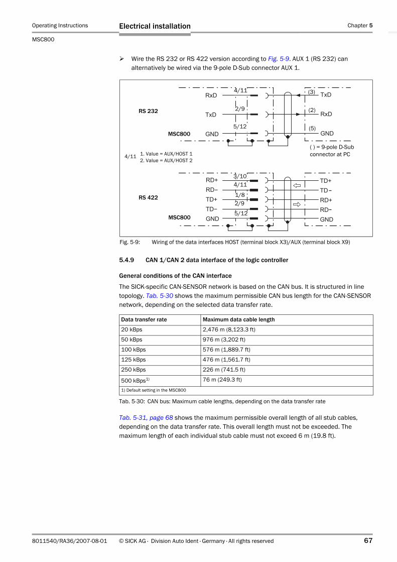
Operating Instructions Chapter 5
MSC800
Electrical installation
8011540/RA36/2007-08-01 © SICK AG · Division Auto Ident · Germany · All rights reserved 67
Wire the RS 232 or RS 422 version according to Fig. 5-9. AUX 1 (RS 232) can alternatively be wired via the 9-pole D-Sub connector AUX 1.
5.4.9 CAN 1/CAN 2 data interface of the logic controller
General conditions of the CAN interface
The SICK-specific CAN-SENSOR network is based on the CAN bus. It is structured in line topology. Tab. 5-30 shows the maximum permissible CAN bus length for the CAN-SENSOR network, depending on the selected data transfer rate.
Tab. 5-31, page 68 shows the maximum permissible overall length of all stub cables, depending on the data transfer rate. This overall length must not be exceeded. The maximum length of each individual stub cable must not exceed 6 m (19.8 ft).
Fig. 5-9: Wiring of the data interfaces HOST (terminal block X3)/AUX (terminal block X9)
RS 232
RS 422
MSC800
MSC800
(3)
(2)
(5)
( ) = 9-pole D-Sub connector at PC
3/104/11
1/8
4/11
2/9
5/12
2/9
5/12
1. Value = AUX/HOST 12. Value = AUX/HOST 2
4/11
Data transfer rate Maximum data cable length
20 kBps 2,476 m (8,123.3 ft)
50 kBps 976 m (3,202 ft)
100 kBps 576 m (1,889.7 ft)
125 kBps 476 m (1,561.7 ft)
250 kBps 226 m (741.5 ft)
500 kBps1) 76 m (249.3 ft)
1) Default setting in the MSC800
Tab. 5-30: CAN bus: Maximum cable lengths, depending on the data transfer rate

Chapter 5 Operating Instructions
MSC800 Modular System Controller
68 © SICK AG · Division Auto Ident · Germany · All rights reserved 8011540/RA36/2007-08-01
Electrical installation
The required wire cross section of the data cable depends on the overall length of the network. Tab. 5-32 shows an overview according to ISO 11898.
Tab. 5-33 shows the maximum permissible CAN bus length, depending on the number of connected CLV490 Bar Code Scanners. This overall length must not be exceeded.
Wiring the CAN 1/CAN 2 data interface of the logic controller
Via the two CAN interfaces of the MSC800 it is possible to connect all the ICR890 Systems as well as further CLV490 Bar Code Scanners and a Volume Measurement System (VMS4xx/5xx). The stub cables have to be terminated at each last device via a resistor.
Data transfer rate Total of all stub cable lengths
125 kBps 156 m (512 ft)
250 kBps 78 m (256 ft)
500 kBps 39 m (128 ft)
Tab. 5-31: CAN bus: Maximum stub cable lengths, depending on the data transfer rate
Cable length Required wire cross section (data cable)
0 to 40 m (0 to 131 ft) ≥ 0.25 mm2 (24 AGW)
40 to 300 m (131 to 984 ft) ≥ 0.34 mm2 (22 AGW)
300 to 600 m (984 to 1,968 ft) ≥ 0.5 mm2 (21 AGW)
600 to 1,000 m (1,968 to 3,280 ft) ≥ 0.75 mm2 (20 AGW)
Tab. 5-32: CAN bus: Required wire cross section, depending on the data cable length
Number of CLV490s Maximum data cable length
2 70 m (230 ft)
3 50 m (164 ft)
4 36 m (118 ft)
5 28 m (92 ft)
6 24 m (79 ft)
7 20 m (66 ft)
8 18 m (59 ft)
9 16 m (52.5 ft)
10 14 m (46 ft)
11 13 m (42.7 ft)
12 12 m (39.4 ft)
Tab. 5-33: CAN bus: Maximum cable lengths, depending on the number of CLV490s

Operating Instructions Chapter 5
MSC800
Electrical installation
8011540/RA36/2007-08-01 © SICK AG · Division Auto Ident · Germany · All rights reserved 69
Distribution of the devices to the two data interfaces CAN 1 and CAN 2 as well as the sequence of the devices depends on the project-specific number and position of the devices.
Example of CAN 1 data interface wiring with a ICR890 System:
Connect the ICR890 System to the 5-pole M12 socket and the open end via the CAN 1-IN connection using the cable no. 6021166. (See Tab. 5-40, page 74 for pin/wire colour assignment.)
Connect the open cable end in the MSC800 to the CAN 1 connection.
Attach the terminal resistance no. 6021167 to the CAN1-OUT connection of the ICR890 System.
The signals for the reading pulse and increment are transmitted to the ICR890 System via the CAN bus. The HOST and AUX data interfaces of the ICR890 System as well as the signals of both switching outputs are accessible via the CAN bus at the MSC800. The MSC800 and the ICR890 Systems have to be configured accordingly as Slave or Master for this purpose (see Chapter 6.3, page 76).
Fig. 5-10: Wiring of the CAN interface with terminal resistance
CLV490 VMS4xx/5xxICR890
. . .
Terminal resistor
MSC800

Chapter 5 Operating Instructions
MSC800 Modular System Controller
70 © SICK AG · Division Auto Ident · Germany · All rights reserved 8011540/RA36/2007-08-01
Electrical installation
5.4.10 Ethernet interface ETHERNET 1 of the logic controller
The Ethernet interface ETHERNET 1 of the MSC800 has several functions:
• Output of the reading result of the HOST data interface via TCP/IP parallel to the serial interface version RS 232, RS 422/485
• Output of the data of the AUX data interface (reading result + reading diagnosis data) via TCP/IP parallel to the serial interface version RS 232, RS 422/485
• Access to the MSC800 via the SOPAS-ET Configuration Software• Connection as RDT400 Client (remote system monitoring)
Connecting Ethernet interface ETHERNET 1 of the logic controller
Connect the MSC800 directly to the Ethernet card of the PC (point-to-point connection) using the crossover cable (see Tab. 10-2, page 98).- or -Connect the MSC800 to the Ethernet network using a standardized data cable (patch cable).
For required settings at the PC and the MSC800 see Chapter 6.3.2, page 77.
5.4.11 Switching inputs IN, TRIGGER and INC of the logic controller
The connection of the reading pulse sensor is carried out via one of the digital switching inputs TRIGGER_1 to TRIGGER_4. The incremental encoder is connected to one of the digital switching inputs INC 1 to INC 4 (max. switching frequency 30 KHz). Fig. 5-12 shows the wiring of switching input TRIGGER_1. If the reading pulse sensor is supplied with external voltage, connection of the switching output can occur at the MSC800 potentially free (DIP switch "SGND _5 - GND" to OFF, connection at terminal 7 n/a). Tab. 5-34 contains the ratings for the input.
Fig. 5-11: Block diagram: Function of the Ethernet interface
MSC800 PC
AUX
HOST
CAN 1
ETHERNET 1
SOPAS-ET
FTP serverPort 21: FTP
Port 2112: Host
Port 2111: AUX
RS 232, RS 422/485
RS 232, RS 422/485
VMS4xx/5xx ICR890 ICR890
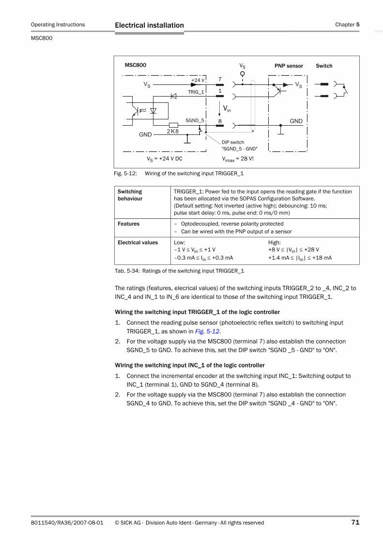
Operating Instructions Chapter 5
MSC800
Electrical installation
8011540/RA36/2007-08-01 © SICK AG · Division Auto Ident · Germany · All rights reserved 71
The ratings (features, elecrical values) of the switching inputs TRIGGER_2 to _4, INC_2 to INC_4 and IN_1 to IN_6 are identical to those of the switching input TRIGGER_1.
Wiring the switching input TRIGGER_1 of the logic controller
1. Connect the reading pulse sensor (photoelectric reflex switch) to switching input TRIGGER_1, as shown in Fig. 5-12.
2. For the voltage supply via the MSC800 (terminal 7) also establish the connection SGND_5 to GND. To achieve this, set the DIP switch "SGND _5 - GND" to "ON".
Wiring the switching input INC_1 of the logic controller
1. Connect the incremental encoder at the switching input INC_1: Switching output to INC_1 (terminal 1), GND to SGND_4 (terminal 8).
2. For the voltage supply via the MSC800 (terminal 7) also establish the connection SGND_4 to GND. To achieve this, set the DIP switch "SGND _4 - GND" to "ON".
Fig. 5-12: Wiring of the switching input TRIGGER_1
PNP sensor SwitchMSC800
VS = +24 V DC Vimax = 28 V!
1
8
7+24 V
TRIG_1
SGND_5
DIP switch"SGND_5 - GND"
VS
Vin
Switching behaviour
TRIGGER_1: Power fed to the input opens the reading gate if the function has been allocated via the SOPAS Configuration Software.(Default setting: Not inverted (active high); debouncing: 10 ms; pulse start delay: 0 ms, pulse end: 0 ms/0 mm)
Features – Optodecoupled, reverse polarity protected– Can be wired with the PNP output of a sensor
Electrical values Low: –1 V ≤ Vin ≤ +1 V –0.3 mA ≤ Iin ≤ +0.3 mA
High:+8 V ≤ |Vin| ≤ +28 V+1.4 mA ≤ |Iin| ≤ +18 mA
Tab. 5-34: Ratings of the switching input TRIGGER_1

Chapter 5 Operating Instructions
MSC800 Modular System Controller
72 © SICK AG · Division Auto Ident · Germany · All rights reserved 8011540/RA36/2007-08-01
Electrical installation
5.4.12 Switching outputs OUT of the logic controller
An appropriate visualization PC or PLC for system status indication is connected via the four digital switching outputs OUT 1 to OUT 4. Fig. 5-13 shows the wiring of switching output OUT_1 as an example. Tab. 5-35 contains the identical ratings of the switching outputs.
Fig. 5-14 shows the wiring of the relay outputs 1 and 2. Tab. 5-36 contains the identical ratings for both relay outputs.
Fig. 5-13: Wiring of the digital switching output OUT_1 (terminal block X7)
�
MSC800 VS
1
8
OUT_1
GNDVout
Switching behaviour PNP switching against the supply voltage VS
Features – short-circuit proof + temperature protected– not isolated from VS
Electrical values (VS − 1.5 V) ≤ Vout < VS at Iout ≤ 100 mA
Tab. 5-35: Ratings of the digital switching outputs OUT_1 to OUT_4
Fig. 5-14: Wiring of the relay outputs
MSC800
5
7
611
1412
MSC800
12
14
1311
1412
Relay output 1 Relay output 2
Switching behaviour Toggle switch
Features Not short-circuit proof, not temperature protected
Electrical values Vswitch ≤ 30 V DC (functional extra-low voltage)Iswitch ≤ 1 A for 24 V DC
Tab. 5-36: Ratings of the relay outputs
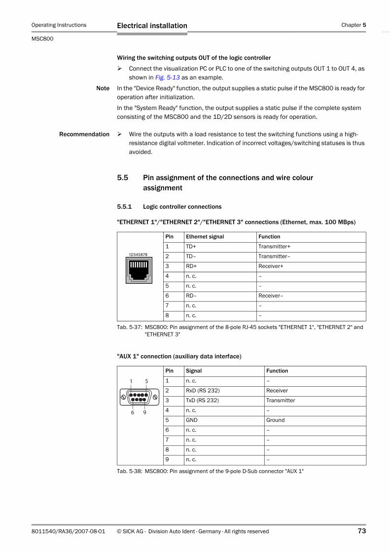
Operating Instructions Chapter 5
MSC800
Electrical installation
8011540/RA36/2007-08-01 © SICK AG · Division Auto Ident · Germany · All rights reserved 73
Wiring the switching outputs OUT of the logic controller
Connect the visualization PC or PLC to one of the switching outputs OUT 1 to OUT 4, as shown in Fig. 5-13 as an example.
Note In the "Device Ready" function, the output supplies a static pulse if the MSC800 is ready for operation after initialization.
In the "System Ready" function, the output supplies a static pulse if the complete system consisting of the MSC800 and the 1D/2D sensors is ready for operation.
Recommendation Wire the outputs with a load resistance to test the switching functions using a high-resistance digital voltmeter. Indication of incorrect voltages/switching statuses is thus avoided.
5.5 Pin assignment of the connections and wire colour assignment
5.5.1 Logic controller connections
"ETHERNET 1"/"ETHERNET 2"/"ETHERNET 3" connections (Ethernet, max. 100 MBps)-
"AUX 1" connection (auxiliary data interface)
Pin Ethernet signal Function
1 TD+ Transmitter+
2 TD– Transmitter–
3 RD+ Receiver+
4 n. c. –
5 n. c. –
6 RD– Receiver–
7 n. c. –
8 n. c. –
Tab. 5-37: MSC800: Pin assignment of the 8-pole RJ-45 sockets "ETHERNET 1", "ETHERNET 2" and "ETHERNET 3"
Pin Signal Function
1 n. c. –
2 RxD (RS 232) Receiver
3 TxD (RS 232) Transmitter
4 n. c. –
5 GND Ground
6 n. c. –
7 n. c. –
8 n. c. –
9 n. c. –
Tab. 5-38: MSC800: Pin assignment of the 9-pole D-Sub connector "AUX 1"

Chapter 5 Operating Instructions
MSC800 Modular System Controller
74 © SICK AG · Division Auto Ident · Germany · All rights reserved 8011540/RA36/2007-08-01
Electrical installation
"PROFIBUS" connection
5.5.2 Wire colour assignment of assembled cables with open end
Cables no. 6021166 (5 m (16.4 ft))/no. 6021175 (10 m (32.8 ft)) for CAN 1-IN connection, PVC free
Pin Signal Function
1 n. c. –
2 n. c. –
3 RxD/TxD (B) Receiving/transmitting data P
4 RTS control Transmitter active
5 GND Ground
6 VCC +5 V DC
7 n. c. –
8 RxD/TxD (A) Receiving/transmitting data N
9 n. c. –
Tab. 5-39: MSC800: Pin assignment of the 9-pole D-Sub connector "PROFIBUS"
Pin Signal Wire colour
1 Shield –
2 CAN_V+ red
3 CAN_GND black
4 CAN_H white
5 CAN_L blue
Tab. 5-40: Wire colour assignment: Cables no. 6021166/no. 6021175 (CAN 1-IN), PVC free
socket

Operating Instructions Chapter 6
MSC800
Operation
8011540/RA36/2007-08-01 © SICK AG · Division Auto Ident · Germany · All rights reserved 75
6 OperationThe MSC800 does not require manual operation. Startup and diagnosis are carried out via the SOPAS-ET Configuration Software.
6.1 Overview of the startup procedure
• Start up the MSC800 with the factory default settings.• Connect the PC with the SOPAS-ET Configuration Software to the MSC800.• In order to optimize the functionality of the logic controller, adjust the configuration of
the MSC800.• Check correct functioning of the MSC800 in reading operation.
6.2 SOPAS-ET Configuration Software
The SOPAS-ET Configuration Software optimizes the MSC800 to the reading conditions on site. The configuration data can be saved and archived as a parameter set (project file) on the PC.
6.2.1 Functions of the SOPAS-ET Configuration Software for the MSC800 (overview)
The online help in the SOPAS-ET Configuration Software describes the general functions of the software and their operation:
MENU, HELP, HELP F1
• Selecting the menu language (German, English)• Setup communication with the MSC800 • Password protected configuration for various operating levels• Recording of data during the current mode (recording and analyzing the data of certain
system memory areas via the data recorder)• Diagnosis of the MSC800
6.2.2 System requirements for the SOPAS-ET Configuration Software
PC system requirements: see the Chapter 3.2.3 Operation requirements, page 28 or the readme file on the CD-ROM "Manuals & Software Auto Ident" (no. 2039442).
6.2.3 Installation of the SOPAS-ET Configuration Software
1. Insert the CD-ROM into the CD-ROM drive.2. If the auto run function is enabled, the start page (table of contents) of the CD-ROM is
automatically displayed in the your browser.3. Select the SOFTWARE folder on top left.4. In the listing select SOPAS-ET CONFIGURATION SOFTWARE.
A table with SOPAS-ET information is displayed.5. Select DOWNLOAD under SOFTWARE FILE.6. In the FILE DOWNLOAD dialog box select the option to install directly from the CD-ROM.
Confirm with OK. The software is automatically saved in the “Programs\SOPAS-ET“ directory on your hard disk.– or –

Chapter 6 Operating Instructions
MSC800 Modular System Controller
76 © SICK AG · Division Auto Ident · Germany · All rights reserved 8011540/RA36/2007-08-01
Operation
Select the option to save the software locally on your local hard disk and confirm with OK.
In the FILE DOWNLOAD dialog box select the desired target directory on your hard disk.The “Setup.exe“ file is then saved at this location.Select OPEN in the dialog box to start the file.
7. The installation program starts and guides you through the installation with screen messages. The software will be entried in the Windows start menu under “Programs\SOPAS-ET“.
8. Then confirm the final installation message by clicking “OK.
6.2.4 Default setting for the SOPAS-ET Configuration Software
6.3 First startup
The logic controller of the MSC800 is optimized to the reading conditions on site via the SOPAS-ET Configuration Software. Starting point for this is the factory default setting which can be adjusted to optimize the logic controller. The SOPAS-ET Configuration Software is used to create an application-specific parameter set which can be loaded into the logic controller and saved/archived as a project file (spr file with configuration data) on the PC.
Parameter Value
User interface language English1)
Units of length Metric
User group (operating level) Machine operator
Download parameter for changes Immediate, temporary (RAM of the MSC800)
Upload parameter after online switching Automatic
Window layout 3 (project tree, help, work area)
Serial communication COM 1: 9,600 Bd/19,200 Bd, 8 data bits, 1 stop bit, no parity
1) The software has to be restarted after changes
Tab. 6-1: Default setting for the SOPAS-ET Configuration Software (excerpt)
Fig. 6-1: Configuration with SOPAS-ET
Opened project file with current parameter set
PC with SOPAS-ET Configuration Software
Saved project file (*.spr) with archived parameter set
Logic controller of the MSC800
Parameter set in the working memory of the logic controller
Permanently saved parameter set
Factory default setting of the logic controller
Flash-PROM
ROM
RAM RAM
Database(hard drive)

Operating Instructions Chapter 6
MSC800
Operation
8011540/RA36/2007-08-01 © SICK AG · Division Auto Ident · Germany · All rights reserved 77
6.3.1 Overview of the configuration procedure
• Connect the data interfaces of the PC and the MSC800• Start the SOPAS-ET Configuration Software and create a new project file• Configure the scan assistant (activate PC communication)• Establish communication with the MSC800• Accept current configuration of the MSC800 in the project tree• Use the password "client" to register at the system as an "authorized client"• Configure the MSC800 for use• If necessary, apply the diagnosis tools "reading diagnosis" and "event monitor"
(online presentation/recording of the switching statuses of switching inputs and outputs as well as data transfers to the host)
• Load the optimized configuration into the MSC800 and save permanently• Save the project file with the configuration data of the MSC800 on the PC
6.3.2 Establish communication with the MSC800
Prerequisite The TCP-IP protocol at the PC has to be active to enable communication via TCP-IP.
Connecting data interfaces
Interconnect the PC and the MSC800 according to Tab. 6-2.
Starting the SOPAS-ET Configuration Software and calling up the scan assistant
1. Switch on the supply voltage to the MSC800.The MSC800 and the 1D/2D code sensors carry out a self-test and are initialized.
2. Switch on the PC and start the SOPAS-ET Configuration Software.The SOPAS-ET Configuration Software opens the program window with an English program interface as standard.
3. In order to change the language setting, click on CANCEL and change the language of the program interface via the menu TOOLS/OPTIONS.
4. Once the language setting has been changed, shut down the SOPAS-ET Configuration Software and carry out a restart.
5. In the dialog window select the option Create NEW PROJECT and click on OK to confirm it.6. In the main window under SCAN WIZARD click on the KONFIGURATION button.
The dialog window SCAN WIZARD appears.
Connection via: At data interface: Comment
MSC800 ETHERNET 1 (10/100 MBps)
Connect the PC (Ethernet interface) and the MSC800 (ETHERNET 1 connection) to a switch using a patch cable or directly via a crossover cable.
MSC800 (optional) AUX 1 (RS 232) Connect the PC via a 3-wire null modem cable no. 2014054 to the 9-pole D-Sub connector AUX 1 of the MSC800.
Tab. 6-2: Connection between the PC with SOPAS-ET Configuration Software and the MSC800

Chapter 6 Operating Instructions
MSC800 Modular System Controller
78 © SICK AG · Division Auto Ident · Germany · All rights reserved 8011540/RA36/2007-08-01
Operation
Configuring the Ethernet connection
1. In the dialog window SCAN WIZARD under INTERNET PROTOCOL/INTERNET PROTOCOL (IP) check the check box for ENABLE IP COMMUNICATION.
2. Click on the ADD... button.3. Enter the IP address of the MSC800 and confirm it via OK in the dialog window.
The dialog window closes. A new entry appears in the IP ADDRESS CONFIGURATION list.4. Confirm settings via OK.
The dialog window ADVANCED SCAN SETTINGS closes.TIP For quick and easy starting the communication via Ethernet a COMMUNICATION WIZARD is
available in the SOPAS-ET Configurations Software in the EXTRA menu.
Configuring the optional serial connection
1. In the dialog window SCAN WIZARD under SERIAL PORT/STANDARD PROTOCOL check the check box for ENABLE SERIAL COMMUNICATION.
2. Click on the ADVANCED... button.3. Under BAUDRATE deactivate all the baud rates except 57.6 kbd.4. Select the following PORT SETTINGS: 8 data bits, no parity, 1 stop bit.5. Confirm settings via OK.
The dialog window ADVANCED SCAN SETTINGS closes.
Carrying out a scan
1. In the dialog window SCAN WIZARD click on the SCAN button.2. Select the listed devices (MSC800) and confirm via ADD DEVICE.
Connected devices are searched for via the connection. The SOPAS-ET Configuration Software inserts the found devices in the project tree and uploads the current parameter set (SYNC CHECK).
3. For configuration of the devices see Chapter 6.3.3, page 78.
6.3.3 Configuring the MSC800
All configurable parameters of the MSC800 are listed in the corresponding device description for the SOPAS-ET Configuration Software. The project tree of the device description acts as a guideline for the configuration.
The function of each respective parameter is explained in a context-sensitive manner in an online help (F1 key). The valid value range and the default setting list the display window "PARAMETER INFO" (right mouse button, when the cursor is positioned over the parameter).
In order to configure a device via the SOPAS-ET Configuration Software, the respective operating level has to be selected in advance. After the start, the SOPAS-ET Configuration Software functions at the user level “Machine operator“.
1. In the menu bar under EXTRAS select the command LOGIN TO DEVICE.2. In the dialog window under USER LEVEL in the list box select the entry AUTHORIZED CLIENT
and enter the word "client" under PASSWORD.Confirm the dialog window via OK.
The previously greyed out parameters on the register tabs are now accessible.

Operating Instructions Chapter 6
MSC800
Operation
8011540/RA36/2007-08-01 © SICK AG · Division Auto Ident · Germany · All rights reserved 79
6.3.4 Load changed parameter set into the logic controller
Changed parameter values are immediately transferred temporarily to the logic controller of the MSC800 depending on the option ("Immediate Download"). To ensure that the changes remain even after a MSC800 restart, the configuration has to be permanently saved in the logic controller.
1. In order to load the current settings into the MSC800, select under MSC800 the command PARAMETER/SAVE PERMANENT.
2. Restart the MSC800.
6.3.5 Save, display and print the current parameter set
When archiving a parameter set it is recommended to not only save the project file but also print out the contents of the file.
1. In order to save the current parameter set, select the menu item SAVE AS in the menu bar under PROJECT.
2. Enter a file name in the dialog window and confirm it via SAVE.The SOPAS-ET Configuration Software saves the current settings in a configuration file "*.spr".
3. In order to print out the current parameter set, select in the menu bar under PROJECT the command PRINT/PRINT PREVIEW.The SOPAS-ET Configuration Software displays a preview of a table with a list of all the parameter values.
4. Click on in the tool bar at the top of the dialog window. The dialog window PRINT for printer configuration appears.
5. Edit the settings accordingly and confirm via OK.The current project settings are printed as a table on several pages.
TIP For saving the current parameter set as a PDF file, the command PRINT/SAVE AS PDF FILE is available in the PROJECT menu.
6.4 Default setting
The values of the default setting are permanently saved in the MSC800 (ROM) and in the database of the SOPAS-ET Configuration Software in the device-specific jar file (see Fig. 6-1, page 76). A PC is not required for MSC800 startup with the default setting.
6.4.1 Resetting the default setting in the MSC800
Prerequisite The SOPAS-ET Configuration Software is connected online to the MSC800.
1. In order to completely discard changes to the parameter set, in the menu bar under MSC800 select the command PARAMETER/LOAD FACTORY DEFAULT.The SOPAS-ET Configuration Software loads the default setting from the database and displays the parameter values in the register tabs.
2. In the menu bar under EXTRAS select the command LOGIN TO DEVICE.3. In the dialog window under USER LEVEL in the list box select the entry AUTHORIZED CLIENT
and enter the word "client" under PASSWORD.Confirm the dialog window via OK.
4. In the menu bar under MSC800 select the command PARAMETER/SAVE PERMANENT.The SOPAS-ET Configuration Software transfers the default setting to the permanent parameter memory (Flash-PROM) of the MSC800.

Chapter 6 Operating Instructions
MSC800 Modular System Controller
80 © SICK AG · Division Auto Ident · Germany · All rights reserved 8011540/RA36/2007-08-01
Operation
Notes:

Operating Instructions Chapter 7
MSC800
Maintenance
8011540/RA36/2007-08-01 © SICK AG · Division Auto Ident · Germany · All rights reserved 81
7 Maintenance
7.1 Maintenance during operation
The MSC800 functions maintenance free.
Recommendation In order to prevent damages to the electrical components caused by overheating, please clean the air inlet and air outlet openings at the cabinet of the MSC800-2100/-2300 and MSC800-3400/-3600 at regular intervals. Soiled or blocked filters at the air inlet and air outlet openings have to be changed immediately.
7.2 Cleaning the MSC800
7.2.1 Cleaning the air inlet and air outlet openings (only MSC800-2100/-2300 and MSC800-3400/-3600)
In order to ensure sufficient cooling for the power supply units in versions MSC800-2100, MSC800-2300, MSC800-3400 and MSC800-3600, make sure that the air inlet and air outlet openings are always clean. This is especially recommended when operating the device in harsh conditions (dust, abrasion,etc.).
Use a soft brush to free the air inlet and air outlet openings on the sides of the cabinets.
7.2.2 Changing filters at the air inlet and air outlet openings (only MSC800-2100/-2300 and MSC800-3400/-3600)
There is a filter pad behind the cover of each air inlet and air outlet opening of the MSC800-2100/-2300 and MSC800-3400/-3600. Soiled or blocked filters can cause overheating of the power supply units and must, therefore, be immediately replaced with new ones. The cabinet of the MSC800 does not have to be opened for this task.
1. Remove the cover of the air inlet and outlet openings on the side of the cabinet. To do so, grip into the half-round cut-out of the cover and remove the cover carefully.
2. Remove the old filter pads and replace each with a new one.3. Re-attach the cover true sided and press the cover down until it audibly locks into posi-
tion.
Fig. 7-1: Cleaning the air inlet and air outlet openings at the cabinet of the MSC800
Air inlet opening with filter
Air outlet opening with filterAir outlet opening with filter
Air inlet opening with filter
MSC800-2100MSC800-2300
MSC800-3400MSC800-3600

Chapter 7 Operating Instructions
MSC800 Modular System Controller
82 © SICK AG · Division Auto Ident · Germany · All rights reserved 8011540/RA36/2007-08-01
Maintenance
7.3 Cleaning further optical effective surfaces
Depending on the system equipment, further sensors with optical effective surfaces can be installed (MLG Light Grid for detecting the object distance and photoelectric reflex switch for external reading pulsing). Soiling of these sensors can cause incorrect switching behaviour.
In order to prevent incorrect switching behaviour, remove soiling from the optical effective surfaces of the external sensors
7.4 Check the incremental encoder
If an incremental encoder is used, check the correct position on the conveyor.
Ensure that the incremental encoder always contact the conveyor so that the friction wheel turns without slipping.
7.5 Replacing components of the MSC800
Incorrect or damaged components of the MSC800 (logic controller, power supply modules) have to be removed and replaced with either new or repaired components.
Repairs to the MSC800 should only be carried out by qualified and authorized SICK AG service staff.
7.5.1 Replacing the logic controller of the MSC800-1100/-2100 or MSC800-2300
Removing connection cables
1. Switch off the supply voltage to the MSC800.2. Loosen and disconnect all cable connectors, sockets and pluggable terminal blocks at
the logic controller.
Replacing the MSC800-0000 logic controller
1. Remove the memory card (SD 1) with the saved parameter set from the defective logic controller (Fig. 3-10, Page 37).
2. Insert the memory card into the slot (SD 1) of the new logic controller accordingly.3. Remove the defective logic controller from the cabinet of the MSC800. Loosen the
fastening screw on the left-hand side of the logic controller and slide the logic controller out towards the right.
4. Assemble the new logic controller in the cabinet of the MSC800 in reverse order.
Reconnecting cables
1. Reconnect and insert all cable connectors, sockets and terminal blocks at the logic controller.
2. Switch on the supply voltage to the MSC800.The MSC800 starts up and loads the parameter set from the memory card into the permanent parameter memory (Flash-PROM) of the logic controller.

Operating Instructions Chapter 7
MSC800
Maintenance
8011540/RA36/2007-08-01 © SICK AG · Division Auto Ident · Germany · All rights reserved 83
7.5.2 Replacing the power supply module of the MSC800
Risk of injuries due to electrical current!
The MSC800 is connected to the power supply (100 to 264 V AC/50 to 60 Hz).
Observe current safety regulations when working with electrical equipment.
1. Switch off the supply voltage to the MSC800.2. Loosen and disconnect all cables at the power supply module. Please make a note of
the wire allocation to the terminals.3. Release the defective power supply module from the cabinet of the MSC800.
To to so, use a suitable screwdriver to push the black clip at the bottom end of the power supply module (front end) forwards.
4. Lift the power supply module and remove it towards the front from the bracket.5. Insert the new power supply module on the top hat rail of the MSC800 and push until
the module audibly locks into position.6. Reconnect all cables to the power supply module.7. Switch on the supply voltage to the MSC800.
7.5.3 Replacing the battery in the logic controller
The real-time clock of the logic controller is powered by a battery. If this battery is flat, it has to be replaced.
1. Remove the black plastic cover from the logic controller (Fig. 7-3, Page 84).2. Remove the battery from its holder and insert a new CR 2032 battery.3. Re-attach the black plastic cover.
Fig. 7-2: Releasing the power supply module
Clip to release the power supply module

Chapter 7 Operating Instructions
MSC800 Modular System Controller
84 © SICK AG · Division Auto Ident · Germany · All rights reserved 8011540/RA36/2007-08-01
Maintenance
4. Dispose of the old battery as hazardous waste according to ROHS Directives (Europe).5. Set the system time using the SOPAS-ET Configuration Software.
Set the MSC800 system time:
Prerequisite The MSC800 must connect to the SOPAS-ET Configuration Software.
1. Login on the MSC800 with the password “Servicelevel“ in the user level “Service“.2. In the device tree double click SYSTEM.3. On the REALTIME CLOCK tab click the SET REALTIME CLOCK button.4. Set the time in the dialog box.5. Perform a download to the MSC800.
7.6 Disposal
Inoperable or irreparable devices must be removed and disposed of in an environmentally friendly manner in accordance with valid country-specific waste disposal guidelines.
SICK AG does not currently accept the return of any devices which can no longer be operated or repaired.
Removing the MSC800 for decommissioning
1. Switch off the supply voltage to the MSC800.2. Disconnect all the connection cables at the MSC800.3. Unscrew and remove the MSC800 from the installation frame.
Disposing of the MSC800
1. Remove the cabinet of the MSC800.2. Remove the electronic assemblies of the MSC800.3. Remove the battery in the logic controller of the MSC800 from its holder (see Tab. 7-3,
page 84) and dispose of it as hazardous waste according to ROHS Directives (Europe).4. Dispose of electronic assemblies as hazardous waste.5. Set aside the cabinet and the cover of the MSC800 as well as the connection cables
for metal recycling.
Fig. 7-3: MSC800: Position of the battery in the logic controller
Battery cover
Operating Instructions Chapter 8
MSC800
Troubleshooting
8011540/RA36/2007-08-01 © SICK AG · Division Auto Ident · Germany · All rights reserved 85
8 TroubleshootingThis chapter describes how errors at the MSC800 Modular System Controller can be recognized and eliminated.
For further information, see the operating instructions "ICR890 High End CCD Camera System" and the operating instructions the futher system components.
8.1 Overview of errors and malfunctions which could occur
8.1.1 Installation error
• Unsuitable positioning of the cabinet of the MSC800– Cables too short– Cabinet cannot be opened– Air inlet or air outlet openings are covered
• Reading pulse sensor has been incorrectly positioned (e. g. internal reading gate opens too late or shuts too early)
• Incremental encoder (optional) positioned incorrectly
8.1.2 Electrical installation error
• Interfaces of the MSC800 wired incorrectly
8.1.3 Configuration error
• Functions have not been adjusted to the local conditions, e. g. parameters for the main data interface set incorrectly
• Selected trigger source for reading pulse incorrect
8.1.4 Malfunctions during operation
• Start/Stop operation: External reading pulse is missing, more than one object is in the reading area
• Tracking operation: Minimum distance of the objects in the direction of transport not achieved
• Device error (hardware/software)

Chapter 8 Operating Instructions
MSC800 Modular System Controller
86 © SICK AG · Division Auto Ident · Germany · All rights reserved 8011540/RA36/2007-08-01
Troubleshooting
8.2 Detailed malfunction analysis
8.2.1 System information
The MSC800 displays errors in various ways. The error output is hierarchised and always allows a detailed analysis:
• Communication errors can occur while transmitting telegrams to the MSC800. In this case, the MSC800 returns an error code.
• Error codes are written into a status protocol for errors which occur during a reading.
8.2.2 Status protocol
Note • The status protocol remains even after switching the device off and on again.• The system differentiates between four error types:
– Information– Warning– Error– Fatal error
The system only saves the last five entries for each of the error types.
Displaying the status protocol with the aid of the SOPAS-ET Configuration Software
In order to display the status protocol, the SOPAS-ET Configuration Software has to be online and connected to the MSC800.
Connect the SOPAS-ET Configuration Software to the device.
Open the project tree MSC800, SERVICE, SYSTEM-STATUS, register tab SYSTEM INFORMATION.
8.3 SICK Support
If an error occurs repeatedly or if you cannot correct an error using the above measures, the MSC800 may be defective. The MSC800 components cannot be repaired by the user, meaning that it is not possible to re-establish functions after a failure. However, the MSC800 components can be rapidly replaced by the user. Please see Chapter 7.3 Cleaning further optical effective surfaces, page 82.
Please contact our local SICK office or subsidary if an error occurs which cannot be eliminated:
• The telephone numbers and email addresses are listed on the back page of this manual.For postal addresses also visit www.sick.com.
Do not send the device to the SICK service without first contacting us.

Operating Instructions Chapter 9
MSC800
Technical data
8011540/RA36/2007-08-01 © SICK AG · Division Auto Ident · Germany · All rights reserved 87
9 Technical data
9.1 MSC800 data sheet
Type MSC800-1100MSC800-2100
MSC800-2300 MSC800-3400MSC800-3600
Function Logic controller1) and power supply unit for max. 14 CLV490
Logic controller1) and power supply unit for CLV network and a ICR890 System
Additional power supply unit for max. two/three ICR890 Systems
MTBF of the device > 80,000 h
MTTR of the device < 5 min (per component)
Number of ICR890 Systems per logic controller
8 8 -
Number of CLV490 Bar Code Scanners per logic controller
24 24 -
Number of Volume Measurement Systems per logic controller
1 1 -
Optical indicators 2 x LED per power supply module6 x LED fuse module (12-pole terminal block), only MSC800-1100/-2100/-230048 x LED logic controller For function of the LEDs see Tab. 3-5, page 38
"Host 1/2" data interface Serial: RS 232, RS 422/485; Ethernet, PROFIBUS-DP, data format (serial interfaces) as well as data output format are adjustable
Data transfer rate, serial 0.3 to 115,2 kbd (RS 232, RS 422/485)
Protocols SICK standard, application-specific protocols on request
"AUX 1/2" data interface Serial: RS 232, RS 422/485; Ethernet data format (serial interfaces) as well as data output format are adjustable)
Data transfer rate 0.3 to 115,2 kbd (RS 232, RS 422/485)
"Ethernet" data interface 10/100 MBps, TCP/IP, FTP, half/full duplex
"PROFIBUS-DP" data interface 12 MBd
"CAN" data interface 2 x, 20 KBps to 1 MBps, CANopen protocol, CAN-SENSOR network
Digital IN switching inputs 14 x digital (6 x IN, 4 x TRIGGER, 4 x INC), configurable, PNP, optically decoupled, Vimax = 28 V, reverse polarity protectedFunction: Start/Stop reading pulse, increment signal, etc.Control: Time or path-basedDebouncing: Min. 3 msSelectable logic level (low -> high, high -> low)
Digital OUT switching outputs 4 x digital, configurable, PNP, Iout max = 100 mA, short-circuit proof Function: Device Ready (stat.), System Ready, Good Read, No Read, Temperature, etc. Adjustable impulse duration (stat., 0 to 65,535 ms or 0 to 10,000 mm (0 to 394 in))Selectable logic level (Low -> High, High -> Low)
Relay outputs OUT 2 x relay, Vswitch = max. 30 V DC, Iswitch = max. 1 A
Electrical connections 1 x service socket (only MSC800-1100/-2100, MSC800-2300)Supply voltage IN: terminal block -X100 Supply voltage OUT: terminal block -X120Supply voltage OUT 12-pole terminal block (only MSC800-1100/-2100/-2300)Logic controller:1 x 9-pole D-Sub connector (AUX 1)3 x 8-pole RJ-45 socket (ETHERNET)2 x USB socket
Tab. 9-1: MSC800 technical specifications
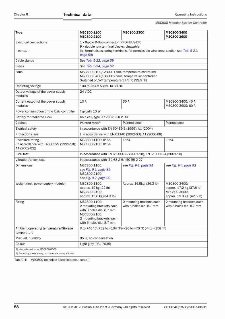
Chapter 9 Operating Instructions
MSC800 Modular System Controller
88 © SICK AG · Division Auto Ident · Germany · All rights reserved 8011540/RA36/2007-08-01
Technical data
Electrical connections
- contd. -
1 x 9-pole D-Sub connector (PROFIBUS-DP)9 x double row terminal blocks, pluggable(all terminals as spring terminals, for permissible wire-cross section see Tab. 5-21, page 59)
Cable glands See Tab. 5-22, page 59
Fuses See Tab. 5-24, page 62
Fans MSC800-2100/-2300: 1 fan, temperature-controlledMSC800-3400/-3600: 2 fans, temperature-controlledSwitched on/off temperature 37.5 °C (99.5 °F)
Operating voltage 100 to 264 V AC/50 to 60 Hz
Output voltage of the power supply modules
24 V DC
Current output of the power supply modules
10 A 30 A MSC800-3400: 40 AMSC800-3600: 60 A
Power consumption of the logic controller Typically 10 W
Battery for real-time clock Coin cell, type CR 2032; 3.0 V DC
Cabinet Painted steel2) Painted steel Painted steel
Eletrical safety in accordance with EN 60439-1 (1999); A1 (2004)
Protection class I, in accordance with EN 61140 (2002-03); A1 (2006-08)
Enclosure rating (in accordance with EN 60529 (1991-10); A1 (2002-02))
MSC800-1100: IP 65 MSC800-2100: IP 54
IP 54 IP 54
EMC test In accordance with EN 61000-6-2 (2001-10), EN 61000-6-4 (2001-10)
Vibration/shock test In accordance with IEC 68-2-6/ IEC 68-2-27
Dimensions MSC800-1100:see Fig. 9-1, page 89MSC800-2100:see Fig. 9-2, page 90
see Fig. 9-3, page 91 see Fig. 9-4, page 92
Weight (incl. power supply module) MSC800-1100: approx. 10 kg (22 lb)MSC800-2100: approx. 15.6 kg (34.3 lb)
Approx. 16.5kg (36.3 lb) MSC800-3400: approx. 17.2 kg (37.8 lb)MSC800-3600: approx. 19.3 kg (42.5 lb)
Fixing MSC800-1100: 2 mounting brackets each with 3 holes dia. 8.7 mmMSC800-2100: 2 mounting brackets each with 5 holes dia. 8.7 mm
2 mounting brackets each with 5 holes dia. 8.7 mm
2 mounting brackets each with 5 holes dia. 8.7 mm
Ambient operating temperature/Storage temperature
0 to +40 °C (+32 to +104 °F)/–20 to +70 °C (-4 to +158 °F)
Max. rel. humidity 95 %, no condensation
Colour Light grey (RAL 7035)1) also referred to as MSC800-00002) Excluding the housing, no materials using silicone
Type MSC800-1100MSC800-2100
MSC800-2300 MSC800-3400MSC800-3600
Tab. 9-1: MSC800 technical specifications (contd.)
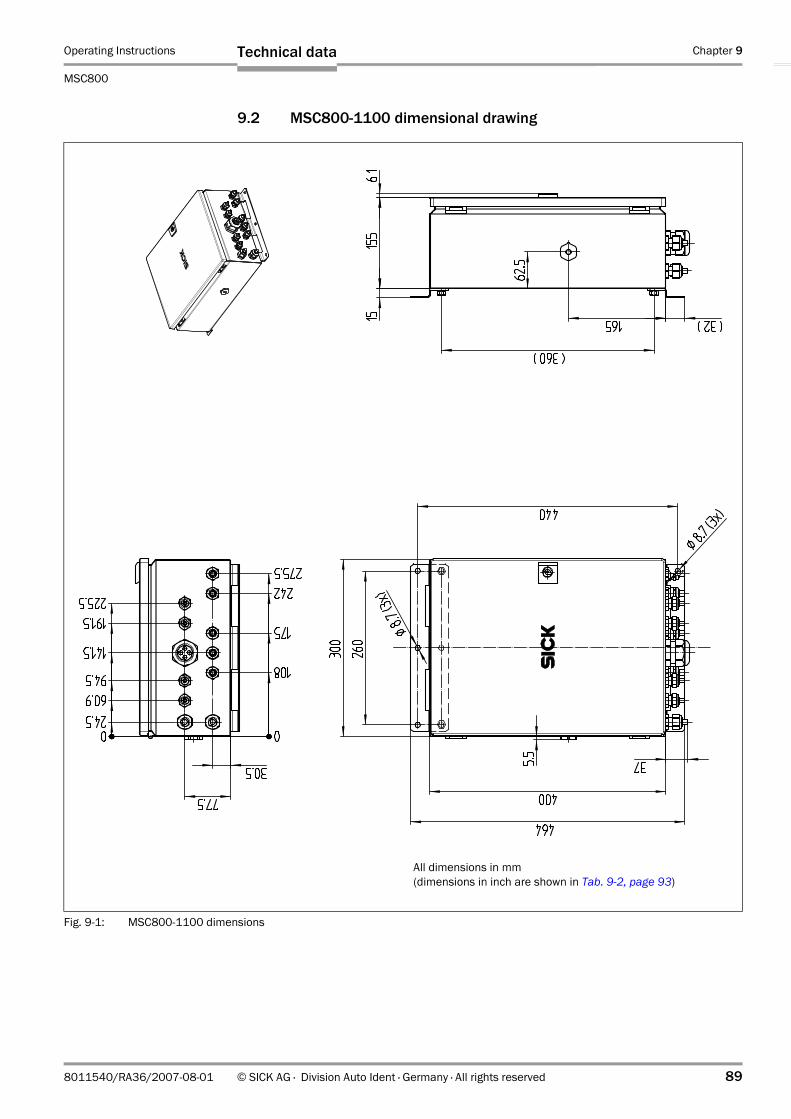
Operating Instructions Chapter 9
MSC800
Technical data
8011540/RA36/2007-08-01 © SICK AG · Division Auto Ident · Germany · All rights reserved 89
9.2 MSC800-1100 dimensional drawing
Fig. 9-1: MSC800-1100 dimensions
All dimensions in mm(dimensions in inch are shown in Tab. 9-2, page 93)

Chapter 9 Operating Instructions
MSC800 Modular System Controller
90 © SICK AG · Division Auto Ident · Germany · All rights reserved 8011540/RA36/2007-08-01
Technical data
9.3 MSC800-2100 dimensional drawing
Fig. 9-2: MSC800-2100 dimensions
All dimensions in mm(dimensions in inch are shown in Tab. 9-2, page 93)

Operating Instructions Chapter 9
MSC800
Technical data
8011540/RA36/2007-08-01 © SICK AG · Division Auto Ident · Germany · All rights reserved 91
9.4 MSC800-2300 dimensional drawing
Fig. 9-3: MSC800-2300 dimensions
All dimensions in mm(dimensions in inch are shown in Tab. 9-2, page 93)
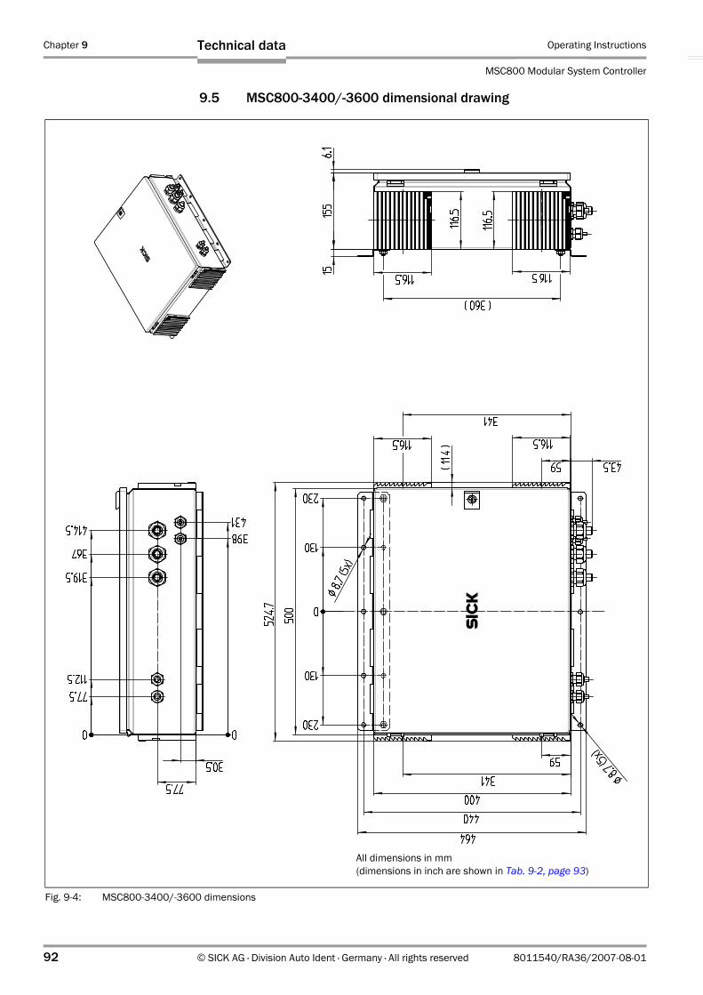
Chapter 9 Operating Instructions
MSC800 Modular System Controller
92 © SICK AG · Division Auto Ident · Germany · All rights reserved 8011540/RA36/2007-08-01
Technical data
9.5 MSC800-3400/-3600 dimensional drawing
Fig. 9-4: MSC800-3400/-3600 dimensions
All dimensions in mm (dimensions in inch are shown in Tab. 9-2, page 93)

Operating Instructions Chapter 9
MSC800
Technical data
8011540/RA36/2007-08-01 © SICK AG · Division Auto Ident · Germany · All rights reserved 93
9.6 Dimensions
MSC800-1100 dimensions shown in Fig. 9-1, page 89
MSC800-2100 dimensions shown in Fig. 9-2, page 90MSC800-2300 dimensions shown in Fig. 9-3, page 91
MSC800-3400/-3600 dimensions shown in Fig. 9-4, page 92
mm inch mm inch mm inch
5.5 0.22 6 0.24 6.1 0.24
6.1 0.24 8.7 0.34 8.7 0.34
8.7 0.34 11.4 0.45 11.4 0.45
15 0.59 15 0.59 15 0.59
24.5 0.97 30.5 1.20 30.5 1.20
30.5 1.20 32 1.26 43.5 1.71
32 1.26 43.5 1.71 59 2.32
37 1.46 57.5 2.27 77.5 3.05
60.9 2.40 58.2 2.29 112.5 4.43
62.5 2.46 59 2.32 116.5 4.59
77.5 3.05 62.5 2.46 130 5.12
94.5 3.72 77.5 3.05 155 6.11
108 4.26 96.5 3.80 230 9.06
141.5 5.58 116.5 4.59 319.5 12.59
155 6.11 130 5.12 341 13.44
165 6.50 132.85 5.23 360 14.18
175 6.90 155 6.11 367 14.46
191.5 7.55 165 6.50 398 15.68
225.5 8.88 166.35 6.55 400 15.76
242 9.53 214 8.43 414.5 16.33
260 10.24 230 9.06 431 16.98
275.5 10.85 275.5 10.85 440 17.34
300 11.82 311 12.25 464 18.28
360 14.18 341 13.44 500 19.70
400 15.76 344.5 13.57 524.7 20.67
440 17.34 360 14.18
464 18.28 361.25 14.23
378 14.89
394.75 15.55
400 15.76
411.5 16.21
440 17.34
445 17.53
464 18.28
475.5 18.73
500 19.70
524.7 20.67
Tab. 9-2: Dimensions shown in Fig. 9-1, page 89, Fig. 9-3, page 91 and Fig. 9-4, page 92
Chapter 9 Operating Instructions
MSC800 Modular System Controller
94 © SICK AG · Division Auto Ident · Germany · All rights reserved 8011540/RA36/2007-08-01
Technical data
Notes:

Operating Instructions Chapter 10
MSC800
Appendix
8011540/RA36/2007-08-01 © SICK AG · Division Auto Ident · Germany · All rights reserved 95
10 Appendix
10.1 Appendix overview
The appendix contains the following additional information:
• Configuring with command strings• Help table for calculating code length of a bar code• Ordering information• Supplementary documentation (overview)• Glossary• Image of EC Declaration of Conformity
10.2 Configuring the ICR890 System with command strings
As an alternative to the SOPAS-ET Configuration Software MSC800 can also be configured and operated with command strings via all the data interfaces.
Note Both the command strings and the SOPAS-ET Configuration Software are based on command language which directly accesses the command interpreter of the MSC800. This command language must be used with care, since the commands sent to the MSC800 are executed immediately. Parameter values altered via commands are at first only active in the current parameter set in the working memory (RAM) of the MSC800. To save in the permanent memory, the altered parameter set must be copied into the EEPROM using a special command, this ensures that the alterations are not lost when the power supply is switched off.
Command listing on request.

Chapter 10 Operating Instructions
MSC800 Modular System Controller
96 © SICK AG · Division Auto Ident · Germany · All rights reserved 8011540/RA36/2007-08-01
Appendix
10.3 Ordering information
10.3.1 MSC800 Modular System Controller
Order no. Description Display
1040385 MSC800-1100 (logic controller and power supply module 24 V DC/10 A)
1041611 MSC800-2300 (logic controller and power supply module 24 V DC/10 A)
1040386 MSC800-2300 (logic controller and power supply module 24 V DC/30 A)
1041770 MSC800-3400 (power supply module 24 V DC/40 A)
1040387 MSC800-3600 (power supply module 24 V DC/60 A)
Tab. 10-1: Ordering information: MSC800 Modular System Controller

Operating Instructions Chapter 10
MSC800
Appendix
8011540/RA36/2007-08-01 © SICK AG · Division Auto Ident · Germany · All rights reserved 97
Note For an exact type designation of the MSC800 see the type plate on the device.
1040571 MSC800-0000 (logic controller)
2039442 1 x CD-ROM "Manuals & Software Auto Ident" –
2034693 1 x WL18-3 Reading Pulse Sensor (photoelectric reflex switch) with connection cable and installation kit
2041013 MLG Light Grid (incl. cable and connector)
Order no. Description Display
Tab. 10-1: Ordering information: MSC800 Modular System Controller (contd.)
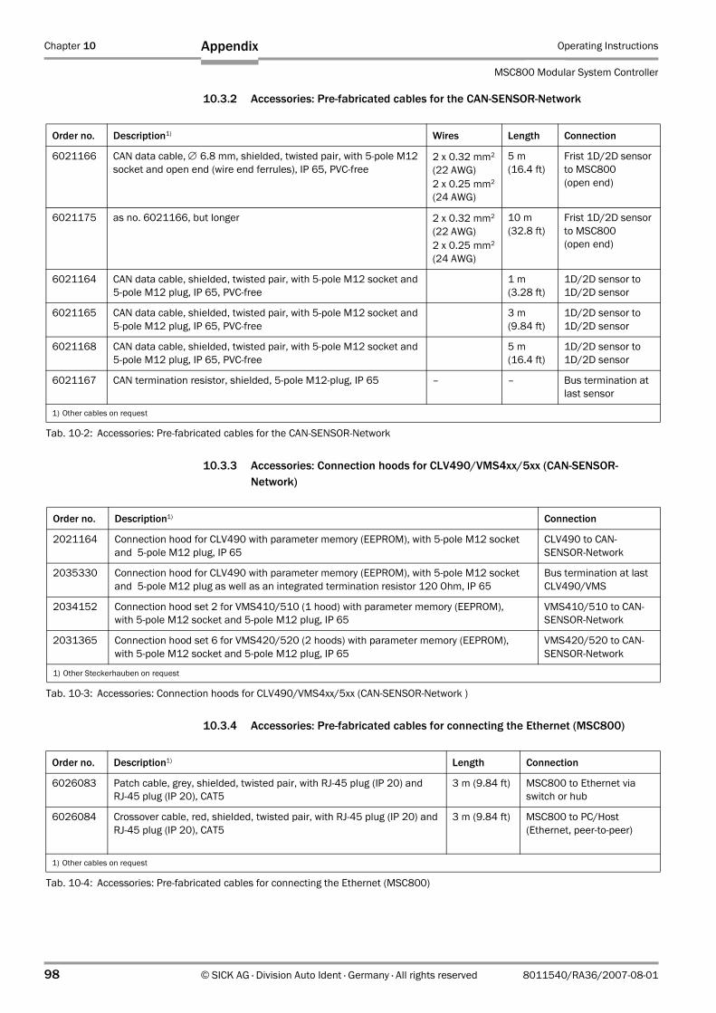
Chapter 10 Operating Instructions
MSC800 Modular System Controller
98 © SICK AG · Division Auto Ident · Germany · All rights reserved 8011540/RA36/2007-08-01
Appendix
10.3.2 Accessories: Pre-fabricated cables for the CAN-SENSOR-Network
10.3.3 Accessories: Connection hoods for CLV490/VMS4xx/5xx (CAN-SENSOR-Network)
10.3.4 Accessories: Pre-fabricated cables for connecting the Ethernet (MSC800)
Order no. Description1) Wires Length Connection
6021166 CAN data cable, ∅ 6.8 mm, shielded, twisted pair, with 5-pole M12 socket and open end (wire end ferrules), IP 65, PVC-free
2 x 0.32 mm2
(22 AWG)2 x 0.25 mm2
(24 AWG)
5 m(16.4 ft)
Frist 1D/2D sensor to MSC800 (open end)
6021175 as no. 6021166, but longer 2 x 0.32 mm2
(22 AWG)2 x 0.25 mm2
(24 AWG)
10 m(32.8 ft)
Frist 1D/2D sensor to MSC800 (open end)
6021164 CAN data cable, shielded, twisted pair, with 5-pole M12 socket and 5-pole M12 plug, IP 65, PVC-free
1 m(3.28 ft)
1D/2D sensor to 1D/2D sensor
6021165 CAN data cable, shielded, twisted pair, with 5-pole M12 socket and 5-pole M12 plug, IP 65, PVC-free
3 m(9.84 ft)
1D/2D sensor to 1D/2D sensor
6021168 CAN data cable, shielded, twisted pair, with 5-pole M12 socket and 5-pole M12 plug, IP 65, PVC-free
5 m(16.4 ft)
1D/2D sensor to 1D/2D sensor
6021167 CAN termination resistor, shielded, 5-pole M12-plug, IP 65 – – Bus termination at last sensor
1) Other cables on request
Tab. 10-2: Accessories: Pre-fabricated cables for the CAN-SENSOR-Network
Order no. Description1) Connection
2021164 Connection hood for CLV490 with parameter memory (EEPROM), with 5-pole M12 socket and 5-pole M12 plug, IP 65
CLV490 to CAN-SENSOR-Network
2035330 Connection hood for CLV490 with parameter memory (EEPROM), with 5-pole M12 socket and 5-pole M12 plug as well as an integrated termination resistor 120 Ohm, IP 65
Bus termination at last CLV490/VMS
2034152 Connection hood set 2 for VMS410/510 (1 hood) with parameter memory (EEPROM), with 5-pole M12 socket and 5-pole M12 plug, IP 65
VMS410/510 to CAN-SENSOR-Network
2031365 Connection hood set 6 for VMS420/520 (2 hoods) with parameter memory (EEPROM), with 5-pole M12 socket and 5-pole M12 plug, IP 65
VMS420/520 to CAN-SENSOR-Network
1) Other Steckerhauben on request
Tab. 10-3: Accessories: Connection hoods for CLV490/VMS4xx/5xx (CAN-SENSOR-Network )
Order no. Description1) Length Connection
6026083 Patch cable, grey, shielded, twisted pair, with RJ-45 plug (IP 20) and RJ-45 plug (IP 20), CAT5
3 m (9.84 ft) MSC800 to Ethernet via switch or hub
6026084 Crossover cable, red, shielded, twisted pair, with RJ-45 plug (IP 20) and RJ-45 plug (IP 20), CAT5
3 m (9.84 ft) MSC800 to PC/Host(Ethernet, peer-to-peer)
1) Other cables on request
Tab. 10-4: Accessories: Pre-fabricated cables for connecting the Ethernet (MSC800)

Operating Instructions Chapter 10
MSC800
Appendix
8011540/RA36/2007-08-01 © SICK AG · Division Auto Ident · Germany · All rights reserved 99
10.3.5 Accessories: Incremental encoder (MSC800)
10.3.6 Accessories: Filter pad for MSC800-2100/-2300/-3400/-3600
10.3.7 Spare parts for MSC800-1100/-2100/-2300/-3600
10.3.8 Spare parts for MSC800-3400
Order no. Description
2039455 Incremental encoder with friction wheel, resolution 10 mm (394 mil)/pulse, max. 100 kHz, operating voltage 10 to 30 V DC, operating temperature 0 to +60 °C (+32 to +140 °F). With fixing bracket and fixing material, 10 m (32.8 ft) connection cable with 5-pole M12 socket and open end. For operation with the MSC800 System and an MLG Light Grid.
2039457 Incremental encoder with friction wheel, resolution 0.2 mm (7.9 mil)/pulse, max. 100 kHz, operating voltage 10 to 30 V DC, operating temperature 0 to +60 °C (+32 to +140 °F). With fixing bracket and fixing material, 10 m (32.8 ft) connection cable with 5-pole M12 socket and open end. For operation with the MSC800 System and a VMS4xx/5xx.
2039456 Incremental encoder with friction wheel, resolution 1 mm (39.4 mil)/pulse, max. 100 kHz, operating voltage 10 to 30 V DC, operating temperature 0 to +60 °C (+32 to +140 °F). With fixing bracket and fixing material, 10 m (32.8 ft) connection cable with 5-pole M12 socket and open end. Application-dependent usage (not for operation with VMS4xx/5xx).
Tab. 10-5: In stock accessories: Incremental encoder
Order no. Description
On request Filter pad for air inlet and air outlet opening
Tab. 10-6: In stock accessories: Filter pad for MSC800-2100/-2300/-3400/-3600
Order no. Description Display
6032868 Power supply module, input 100 to 264 V AC/50 to 60 Hz, output 24 V DC/10 A
Tab. 10-7: Ordering information: Spare parts for MSC800-1100/-2100/-2300/-3600
Order no. Description Display
6033968 Power supply module, input 100 to 264 V AC/50 to 60 Hz, output 24 V DC/20 A
Tab. 10-8: Ordering information: Spare parts for MSC800-3400
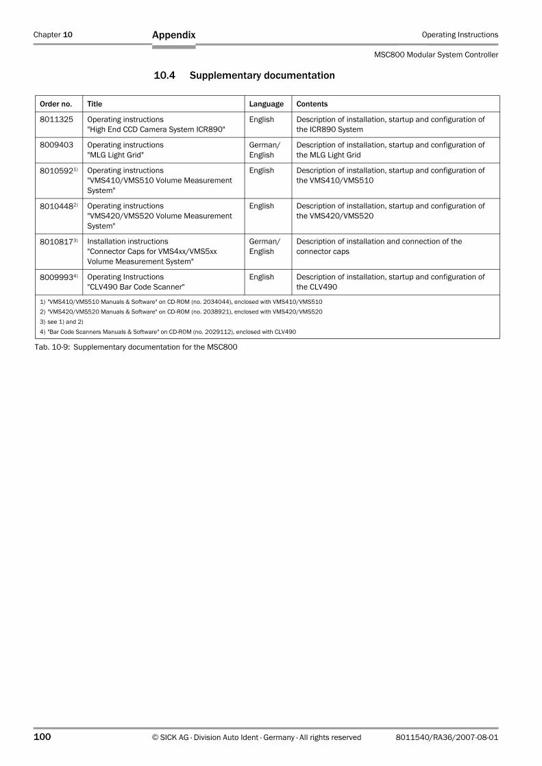
Chapter 10 Operating Instructions
MSC800 Modular System Controller
100 © SICK AG · Division Auto Ident · Germany · All rights reserved 8011540/RA36/2007-08-01
Appendix
10.4 Supplementary documentation
Order no. Title Language Contents
8011325 Operating instructions "High End CCD Camera System ICR890"
English Description of installation, startup and configuration of the ICR890 System
8009403 Operating instructions "MLG Light Grid"
German/English
Description of installation, startup and configuration of the MLG Light Grid
80105921) Operating instructions "VMS410/VMS510 Volume Measurement System"
English Description of installation, startup and configuration of the VMS410/VMS510
80104482) Operating instructions "VMS420/VMS520 Volume Measurement System"
English Description of installation, startup and configuration of the VMS420/VMS520
80108173) Installation instructions "Connector Caps for VMS4xx/VMS5xx Volume Measurement System"
German/English
Description of installation and connection of the connector caps
80099934) Operating Instructions "CLV490 Bar Code Scanner"
English Description of installation, startup and configuration of the CLV490
1) "VMS410/VMS510 Manuals & Software" on CD-ROM (no. 2034044), enclosed with VMS410/VMS5102) "VMS420/VMS520 Manuals & Software" on CD-ROM (no. 2038921), enclosed with VMS420/VMS5203) see 1) and 2)4) "Bar Code Scanners Manuals & Software" on CD-ROM (no. 2029112), enclosed with CLV490
Tab. 10-9: Supplementary documentation for the MSC800

Operating Instructions Chapter 10
MSC800
Appendix
8011540/RA36/2007-08-01 © SICK AG · Division Auto Ident · Germany · All rights reserved 101
10.5 Glossary
Also see the SOPAS-ET Configuration Software online help for further terms.
1D code (bar code, strip code)
Field of dark strips (bars) and light spaces (elements) arranged in parallel, which, by working to a certain rule (specification), can be represented on the medium (subsurface) by various print processes. A user-readable (alpha)numeric character is produced from each machine-readable, corresponding number and combination of strips and spaces. Since the entire coded information, framed by start and stop characters, is available as a whole in one dimension and is also mostly analyzed by line, these bar codes are referred to as linear codes. The various code types differ in their codeable character inventory, design (number of elements per character, number of characters, start/stop characters, check characters), in the information density and in their print tolerances. The length of the code strips and spaces has no bearing on the information content. However, longer code strips and spaces can be more easily analyzed by the reading device.
2D codes
In two dimensional codes the information is arranged more densely in a matrix with the help of dark and light cells (quadrates). The vertical and horizontal arrangement of the cells in relation to the reference points in the centre and on the edges, determines the data content which is defined by the specification. In the case of error correction during reading, the code is tagged with a redundancy by way of a mathematical process (e. g. for DataMatrix ECC200 via error correction code words). The unidirectional reading of 2D codes is carried out by way of image processing.
Auxiliary interface
Logical auxiliary data interface of the MSC800 in double design (AUX 1/2). Each logical in-terface is physically switchable to serial RS 232, RS 422/485 and in parallel to Ethernet (standard: port 2111 respectively port 2113). The serial data interfaces are used for diag-nosis (output of reading diagnosis data or monitoring the data traffic on the host interfaces with a fixed data output format). They also provide special protocols or customer-specific data output formats as well as adjustable data formats and data transfer rates. The data output of the serial data interfaces can each be switched off. The two Ethernet auxiliary ports are used for sending reading diagnosis data with a fixed data output format. The aux-iliary 2 port also provides special protocols or customer-specific data output formats. The data output of auxiliary 2 port can be switched off but not the data output of auxiliary 1 port. Via this auxiliary data interfaces using the SOPAS-ET Configuration Software it is always pos-sible to access the MSC800 for operation and configuration.
CAN interface
Physical data interface. Controls construction of a rapid SICK-specific CAN SENSOR network with various functions (e. g. multiplexer, master/slave) or integration into existing CAN networks after the CANopen protocol. Via the CAN interface (network) using the SOPAS-ET Configuration Software in remote mode it is possible to access the MSC800 for operation and configuration.
Capture area
Zone which a 1D/2D code sensor/the MSC800 sets up around a moving code using the increment management and the reading angle comparison. Allows, among other functions, the separation of codes with identical content, where the code type is the same.

Chapter 10 Operating Instructions
MSC800 Modular System Controller
102 © SICK AG · Division Auto Ident · Germany · All rights reserved 8011540/RA36/2007-08-01
Appendix
Command strings, commands
User interface to the MSC800, as an alternative to the SOPAS-ET configuration software. The command string form a clearly structured command language for changing the parameter value sets in the MSC800 online. Directly accesses the command interpreter of the MSC800. Use of the host requires a corresponding programming task. The SOPAS-ET configuration software is based on the command strings.
Configuration file
Project file for the SOPAS-ET configuration software in which either only one complete para-meter value set for a device or, if several devices are grouped into one project, the complete parameter value set for each device, is saved for archiving on the PC. The project file can be expressed as a table, transferred to the buffer or provided as a PDF.
Data output string
A structured data telegram for the reading results in two independent data output formats that the MSC800 itself prepares for output from its database. The output formats can be output via the host interfaces (HOST 1/2) to the physical data interfaces RS 232/RS 422/485, Ethernet or CAN. The design of the output formats is flexible (sequence of the code segments and elements, link with event conditions, filters, sorters etc.) and can be widely adapted to the application-specific requirements. However, the data output formats of the auxiliary interfaces (AUX 1/2) cannot be altered.
Decoder, decoding
From the code type-dependent analysis routine to reconstruction of the codes read in electronic form, in order to decipher the data content.
Download
Transfer process of the parameter values using the SOPAS-ET Configuration Software from the PC to the connected MSC800. In "Online" communication mode, the SOPAS-ET Configuration Software always transfers the just modified parameter values in the background automatically and temporarily to the memory (RAM) of the MSC800 with the "Immediate Download" option. With this option, the current parameter values in the MSC800 are constantly synchronised with the modifications that are made on the user interface. With the "Download on Request“ option, the user is responsible for comparing them manu-ally. If individual parameter values have unsynchronized statuses between SOPAS-ET and the connected MSC800, SOPAS-ET identifies these parameters with a blue frame. Using the context menu (right mouse button), if necessary the modified parameter value on a register tab (DOWNLOAD PARAMETER TO DEVICE) can be transferred manually to the MSC800. Using the COMMUNICATION menu, either modified parameter values only (DOWNLOAD CHANGED PARAMETERS TO DEVICE) or all of the MSC800's parameter values (DOWNLOAD ALL PARAMETERS TO DEVICE) can be transferred.The parameter values that were temporarily changed in the MSC800 are only saved permanently when the storage option "permanent“ (menu CLV62X) is selected. The trans-ferable parameter values depend on the current user level in SOPAS-ET.
Error messages
Messages in coded form with which the MSC800 displayed a diagnosed error. The MSC800 differentiates between four error types: Information, Warning, Error, Fatal Error. The error messages can be displayed in the SOPAS-ET configuration software on the SYSTEM INFORMATION register tab.

Operating Instructions Chapter 10
MSC800
Appendix
8011540/RA36/2007-08-01 © SICK AG · Division Auto Ident · Germany · All rights reserved 103
Ethernet interface (Host)
Physical data interface with transfer rate 10/100 MBit/s, TCP/IP and FTP protocols. The Ethernet interface can be used for the host interfaces (HOST 1/2) and the auxiliary interfaces (AUX 1/2) alternatively to and also in parallel with the physical interfaces RS 232, RS 422/485. Via the four Ethernet ports using the SOPAS-ET Configuration Software it is always possible to access the MSC800 for configuration.
Function interfaces
Digital switching inputs and outputs as well as relay outputs of the MSC800.
Good Read
The defined evaluation condition(s) were successfully met during the last reading pulse in the reading process.
Help input
Special function of the Aux interface. Allows the additional manual input of code data for completion of the reading results sent to the host.
Host interface
Logical main data interface of the MSC800 in double design (HOST 1/2) with two independent, configurable data output formats. Allows, among other functions, the output of the reading result in telegram form to the host/PLC. Physically switchable to RS 232/RS 422/485 and in parallel to Ethernet (standard: port 2112 respectively port 2114) as well as to CAN. Works as a gateway in conjunction with the SICK-specific CAN-SENSOR network. Provides various transfer protocols (except for CAN) or customer-specific data output formats. The data formats and the data transfer rates of the serial data interfaces are each adjustable, the data output can be switched off. An existing parallel data output via Ethernet remains active. However, the data output of the Ethernet Host ports can be switched off separately. With the host interface, access to the bar code scanner for configuration and diagnosis is also possible with the SOPAS-ET configuration software.
Master/Slave configuration
Special arrangement and technical circuit connection of 1D/2D code sensors to one reading station (e. g. multi-side reading) using the CAN interface. Via the MSC800 as master the combination acts on the host as just one device.
Multi-reading
Selectable number of readings which must each deliver identical internal results from one and the same bar code before a 1D/2D code sensor generates the reading result.
No read
The defined evaluation condition(s) were not met during the last reading pulse in the rea-ding process.
No read format
Special, configurable output format for no reads in the data output string as a replacement for the output formats of a reading with fulfilled evaluation conditions. In its default setting, the MSC800 outputs the "NoRead" string as the no read format, framed by STX and EXT.

Chapter 10 Operating Instructions
MSC800 Modular System Controller
104 © SICK AG · Division Auto Ident · Germany · All rights reserved 8011540/RA36/2007-08-01
Appendix
Object distance, object height
Gauge for focussing a 1D/2D code sensor. Determined, e. g., by means of an MLG Light Grid during reading from above or VMS4xx/5xx Volume Measurement System on the conveyor system during reading from side.
Parameter set
Data set which is used to initialize and activate the implemented functions of the MSC800. Transferred using the upload (all parameter values only) or download from the MSC800 to the SOPAS-ET Configuration Software or vice versa.
Reading angle (RA value)
For the decoding process, the active analysis area within the illumination line of the ICR890 respectively within the scanning line of a CLV bar code scanner can be restricted application-specifically by presetting the minimum and maximum RA values.
Reading diagnosis data
Code-, object- or device-related data which the MSC800 derives directly from the reading process. The data allows, among other things, an assessment of the reading quality and to draw conclusions on the reading process.
Reading pulse
Triggering of the internal reading gate via a MSC800-external pulse at a switching input is carried out object-related by means of an external trigger source such as a photoelectric reflex switch or a command string via the data interface. With internal trigger source "Auto cycle“, the MSC800 creates the reading pulse itself.
Reading result
Electronic display and output of the data contents of the scanned codes together with reading diagnosis data in a data output string at the defined output time
Result status output
Adjustable function of the four independent switch outputs "Result 1" to "Result 4" as well as the both relay outputs of the MSC800. Indicates either the status of the reading result (e.g. good read) or the ful-fillment of a definable, event-dependent evaluation condition for the read operation (such as Match1). The outputs can also indicate system statuses (e. g. fan on). The outputs can be switched off individually. The logic level of each output is selectable.
Saving to the MSC800
The application-specific parameter value set can be stored in the MSC800 either temporarily or permanently. In the case of temporary storage, the parameter value set is only contained in the temporary memory (RAM) and is lost as soon as the power supply is switched off. In the case of permanent storage, the parameter value set is also transferred to the MSC800’s permanent memory and saved as a current data set after switching off. The default setting is deposited in a fixed, Read Only Memory (ROM) irrespective of this.
Sending point
Output time of the reading result in relation to the start of the reading pulse and the fulfilled evaluation conditions.

Operating Instructions Chapter 10
MSC800
Appendix
8011540/RA36/2007-08-01 © SICK AG · Division Auto Ident · Germany · All rights reserved 105
SMART decoder
Specially developed decoder for reading bar codes with extremely small code heights and or bad or soiled print images.
SOPAS-ET
PC configuration software, to run on Windows98TM, METM, NT4.0TM, 2000TM, XPTM and VistaTM. Used for online communication with the MSC800 in the dialog (configuration, displaying reading events, diagnosis) as well as for preparatory offline configuration of stand-alone devices or the grouping of the same/different SOPAS-ET-compatible SICK devices in a project. The parameters are exchanged device-specific with the MSC800/the devices via upload and download.
SOPAS-ET Help
Online help which supports use of the SOPAS-ET configuration software. The parameter functions of the MSC800 are explained in the online help. Runs using an HTML browser, such as “Internet ExplorerTM“, and can be called up in the SOPAS-ET configuration software.
Start/Stop operation
In this operation mode (separate reading pulses), only one object per reading pulse is located in the reading area. External sensors or command strings control the beginning and end of the reading pulse for the master/slave arrangement of 1D/2D code sensors (e. g. double-side reading) and MSC800. If only one 1D/2D code sensor (stand-alone device, single-side reading) is used together with the MSC800, also the free running mode of the 1D/2D code sensor can control the reading process. The 1D/2D code sensor(s) receive(s) its (their) pulse signals via the MSC800. The length of the reading area is determined in this case by the distance of both external sensors for the start (beginning of the reading area) and stop (end of the reading area) of the reading pulse. The minimum reading distance between two objects must always be greater than the length of the reading area. Networking the 1D/2D code sensor(s) to the MCS800 is carried out via the CAN interface.The MCS800 (master) outputs the reading results via the RS 232/RS 422/485 interfaces and/or via the Ethernet interfaces.
Tracking operation
In this operation mode (continuous reading pulses), several objects are simultaneously located in a row in the reading area, but not parallel. For unambiguous allocation of the read codes to the objects, a minimum gap must be maintained between two objects and band increment signals have to be available for the master/slave arrangement of 1D/2D code sensors (e. g. triple-side reading) and MSC800. The 1D/2D code sensor(s) receive(s) its (their) pulse signals and the band increment values via the MSC800. The length of the reading area is determined in this case by the distance of the external sensor for the beginning/end of the object at the beginning of the reading area and the object release point (data output) of the MSC800 in the direction of transport at the end of the reading area. Networking the 1D/2D code sensor(s) to the MCS800 is carried out via the CAN interface. The 1D/2D code sensors each manage recorded objects by means of an internal object tracking list.
Upload
Transfer process of all parameter values from the connected MSC800 memory (RAM) to a PC in the SOPAS-ET configuration software for display and modification. This is achieved when the device is connected and communication is successfully carried out after the scanning process for a confirmed request to synchronise the user interface and the

Chapter 10 Operating Instructions
MSC800 Modular System Controller
106 © SICK AG · Division Auto Ident · Germany · All rights reserved 8011540/RA36/2007-08-01
Appendix
MSC800. Where necessary, this can be triggered manually in the Kommunikation menu (UPLOAD ALL PARAMETERS FROM DEVICE). Parameter values must be represented in the register tabs before the current parameter value set can be modified.
User interface
Windows-oriented input interfaces in the SOPAS-ET Configuration Software for operation and configuration of the MSC800.

Operating Instructions Chapter 10
MSC800
Appendix
8011540/RA36/2007-08-01 © SICK AG · Division Auto Ident · Germany · All rights reserved 107
10.6 EC Declaration of Conformity
Fig. 10-1 shows a scaled down version of the EC Declaration of Conformity (page 1) for the MSC800-1100/-2100/-2300/-3400/-3600.
The complete EC Declaration of Conformity with the listing of device versions and the fullfilled standards can be requested from SICK AG.
Fig. 10-1: EC Declaration of Conformity for the MSC800-1100/-2100/-2300/-3400/-3600 (page 1, scaled down version)
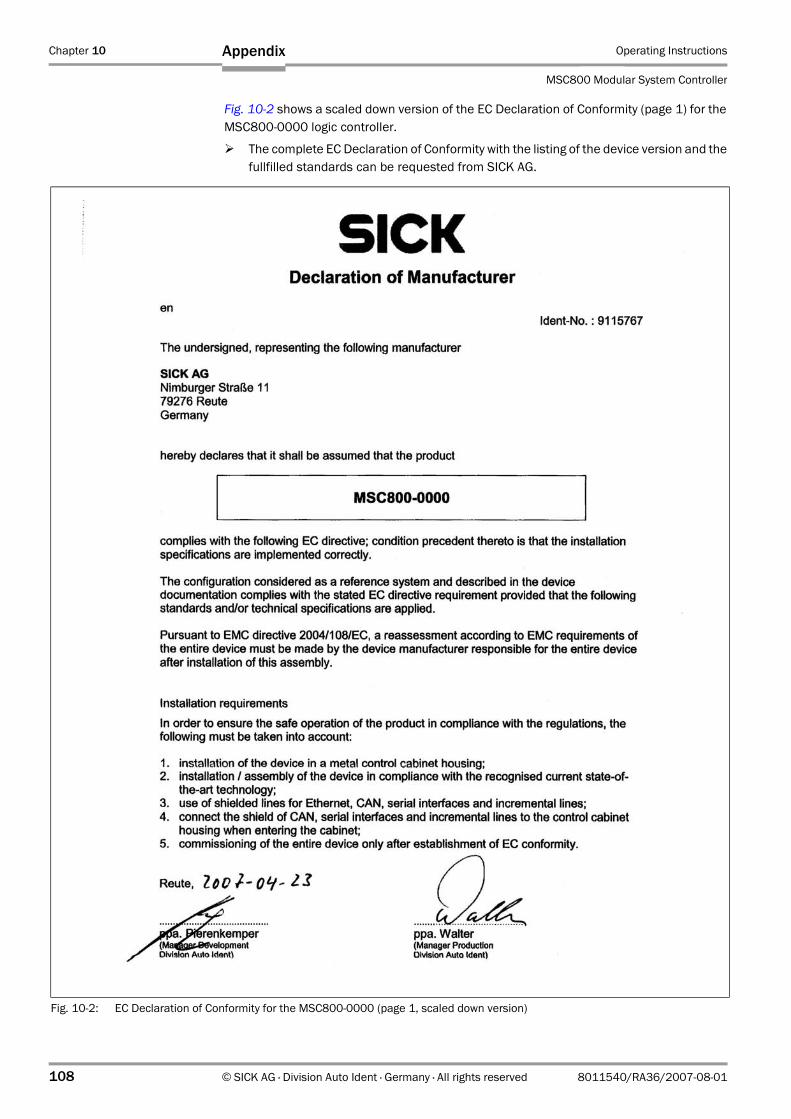
Chapter 10 Operating Instructions
MSC800 Modular System Controller
108 © SICK AG · Division Auto Ident · Germany · All rights reserved 8011540/RA36/2007-08-01
Appendix
Fig. 10-2 shows a scaled down version of the EC Declaration of Conformity (page 1) for the MSC800-0000 logic controller.
The complete EC Declaration of Conformity with the listing of the device version and the fullfilled standards can be requested from SICK AG.
Fig. 10-2: EC Declaration of Conformity for the MSC800-0000 (page 1, scaled down version)

Operating Instructions Chapter 10
MSC800
Appendix
8011540/RA36/2007-08-01 © SICK AG · Division Auto Ident · Germany · All rights reserved 109

SICK AG | Waldkirch | Germany | www.sick.com
80
11
54
0/R
A3
6/2
00
7-0
8-0
1 ·
5M
/TR
<P
M6
.5/F
M7
.0/P
DF
>/V
D ·
Australia
Belgium/Luxembourg
Brasil
Ceská Republika
E-Mail [email protected]
China
Danmark
E-Mail [email protected]
Deutschland
España
France
Great Britain
India
Italia
Japan
Nederlands
Norge
Österreich
Polska
Republic of Korea
Republika Slowenija
România
Russia
E-Mail denis.kesaev@sick-
Schweiz
Singapore
Suomi
Sverige
Taiwan
Türkiye
USA/Canada/México
www.sick.com