Embed Size (px)
Citation preview
MSBE seriesSTOPPER CYLINDER
MSBE ─ 50 ─ 30 ─ D ─ L ─ S ─ GOrder example
Intended useStopping transferred workpiece.
TUBE I.D.(mm)
STROKE(mm)
LEVER LOCKBlank: WithoutL: Lock mechanism
PORT THREADBlank: Rc threadG: G threadNPT: NPT thread
STYLEBlank: Double acting
with spring extend D: Double acting
ROLLER MATERIALBlank: POMS: Steel
MODEL
Specification
Feature● Patented lever-lock mechanism.● Proximity sensors are available.● Adjustable shock absorbers provide good capacity for different
applications.● Magnetic as standard.
Model MSBETube I.D. (mm) ø32 ø50 ø63 ø80
Stroke (mm) 20 30 30 40
Medium Air
Operating pressure range 0.2~1 MPa
Proof pressure 1.5 MPa
Ambient temperature -5~+60°C (No freezing)
Lubrication Not required
CushionExternal stopper Adjustable shock absorber
Internal cylinder NBR cushion pad
Sensor switch RDFE(V) (Please refer to page 8-19)
Proximity sensor RJY (Please refer to page 8-**)
Weight 550 g 1930 g 3410 g 6340 g
Piping diagramDouble acting with spring
Double acting
Lock & Deactivation mechanismLock mechanism prevents the light-weight workpiece from moving back by the force of shock absorber after damping. Deactivation mechanism can deactivate the cylinder without any disassembling.
Workpiece
Conveyor
Lever lock Deactivation
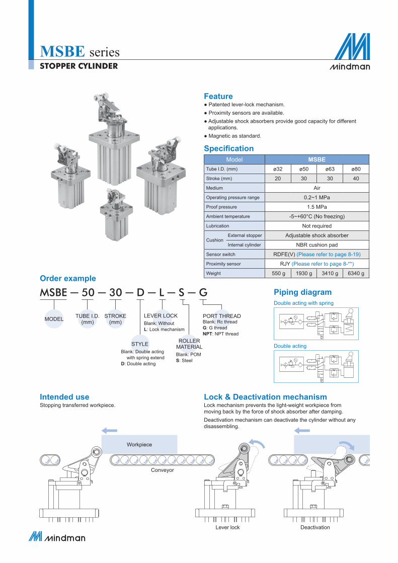
Stop roller (×2)
Roller toggle lever
Thread (×2)
For inductive proximity sensor.
Guide rod For protection against rotation.
Through hole (×4)
For mounting.
(Optional)
Lock mechanismFor activating / deactivating lever position locking mechanism.For ø50~ø80, two pins for lever lock and deactivation mechanism are deliveried for every L type MSBE.The pin for lever lock fucntion is installed before delivery. The other pin is attached in the package.Please see the assembling guide below for installing.
STOPPER CYLINDER
MSBE Mechanism
Pallet control stopper type
1 Unlock bolt (Accessories)The locking / deactivation mechanism of MSBE*-L* can be unlocked/reactivated by return the piston rod.
2 Port installation & Supply port (×2)
Select one set of port between the top one on the front cap and the one at the bottom.
Unlocking locked lever Unlocking free-pass
Connect to the port from the cap.
Connect to the port from the body.a Extending b Retracting
b
a
Knurled capStep 1
Turn knurled cap until the desired cushioning is reached.● Max mark: Cushion becomes harder.● 0 mark: Cushion becomes softer.
Step 2 Tighten lock screw. Tightening torque: 2 N.m
lock screwKnurled cap
ab
Max
Sensor switch groove (×6)
1
2
a
b
1
2
1 Lever-lock function
2 Free-pass function
Upper limit value
MSBE Capacity ø32~ø80STOPPER CYLINDER
ø32-20
Load
wei
ght (
Kg)
Conveyor speed (m/min)0 10 20 30 40
40
30
20
10
Upper limit value
Lower limit value
ø50-30
Load
wei
ght (
Kg)
Conveyor speed (m/min)0 10 20 30 40
400
300
200
100
25
Upper limit value
Lower limit value
ø63-30
Load
wei
ght (
Kg)
Conveyor speed (m/min)0 10 20 30 40
500
400
300
200
100
30
Lower limit value
Upper limit value
ø80-40
Load
wei
ght (
Kg)
Conveyor speed (m/min)0 10 20 30 40
900
800
700
600
500
400
300
200
10060
Lower limit value
Upper limit value
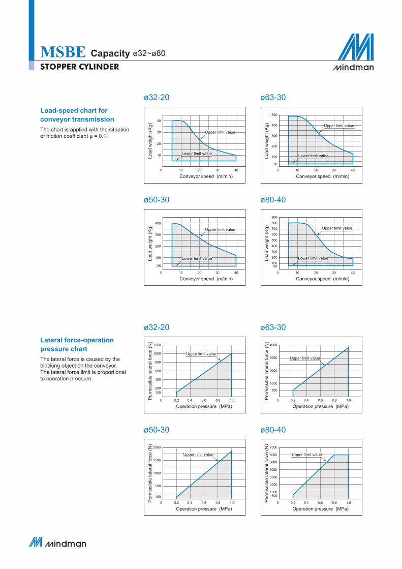
Load-speed chart for conveyor transmissionThe chart is applied with the situation of friction coefficient μ = 0.1.
Lateral force-operation pressure chartThe lateral force is caused by the blocking object on the conveyor. The lateral force limit is proportional to operation pressure.
ø32-20
Per
mis
sibl
e la
tera
l for
ce (N
)
Operation pressure (MPa)0 0.2 0.4 0.6 0.8 1.0
1200
1000
800
600
400
200100
ø50-30
Per
mis
sibl
e la
tera
l for
ce (N
)
Operation pressure (MPa)0 0.2 0.4 0.6 0.8 1.0
2000
1500
1000
500
100
ø63-30
Per
mis
sibl
e la
tera
l for
ce (N
)
Operation pressure (MPa)0 0.2 0.4 0.6 0.8 1.0
ø80-40
Per
mis
sibl
e la
tera
l for
ce (N
)
Operation pressure (MPa)0 0.2 0.4 0.6 0.8 1.0
Upper limit value
Upper limit value Upper limit value
4000
3000
2000
1000
500
7000
6000
5000
4000
3000
2000
1000600
STOPPER CYLINDER
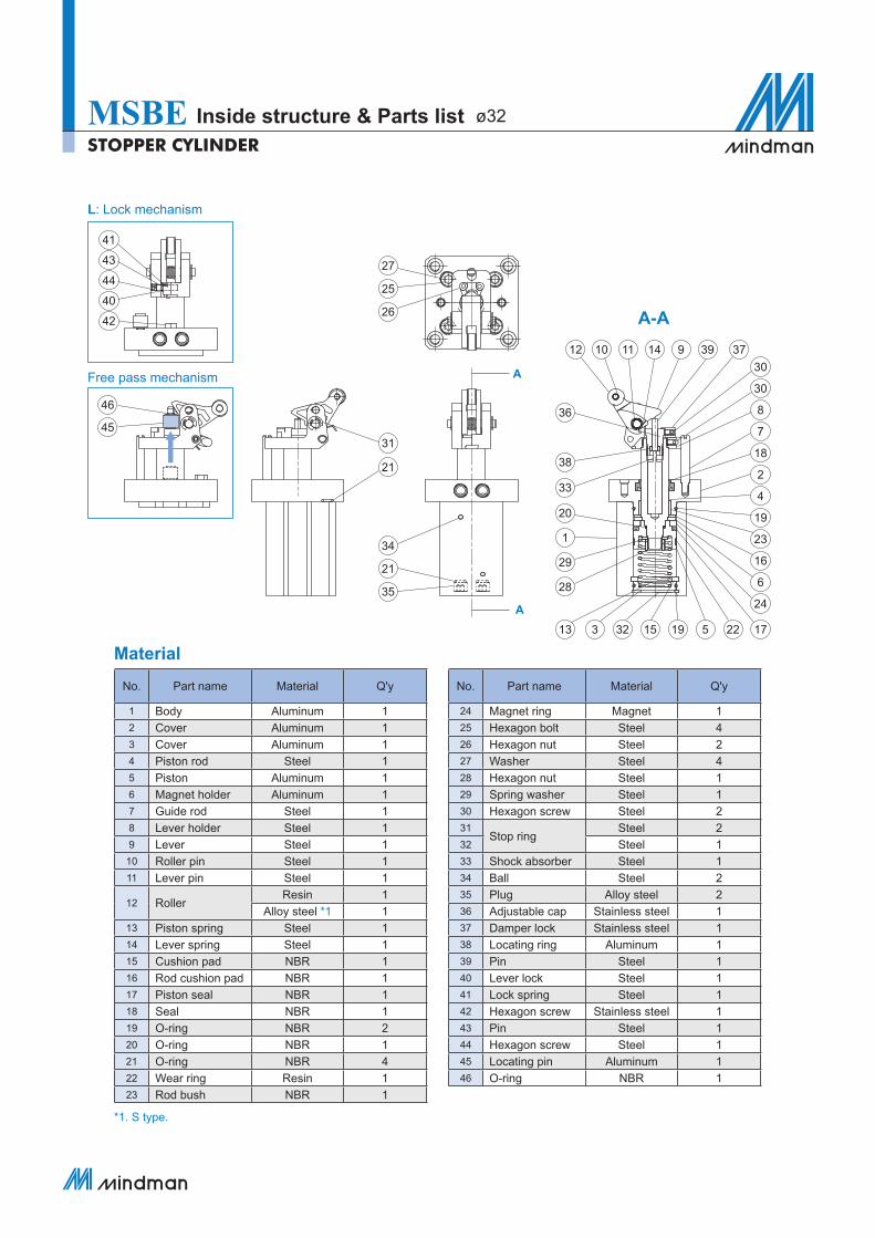
MSBE Inside structure & Parts list ø32
Material
No. Part name Material Q'y
1 Body Aluminum 12 Cover Aluminum 13 Cover Aluminum 14 Piston rod Steel 15 Piston Aluminum 16 Magnet holder Aluminum 17 Guide rod Steel 18 Lever holder Steel 19 Lever Steel 1
10 Roller pin Steel 111 Lever pin Steel 1
12 RollerResin 1
Alloy steel *1 113 Piston spring Steel 114 Lever spring Steel 115 Cushion pad NBR 116 Rod cushion pad NBR 117 Piston seal NBR 118 Seal NBR 119 O-ring NBR 220 O-ring NBR 121 O-ring NBR 422 Wear ring Resin 123 Rod bush NBR 1
No. Part name Material Q'y
24 Magnet ring Magnet 125 Hexagon bolt Steel 426 Hexagon nut Steel 227 Washer Steel 428 Hexagon nut Steel 129 Spring washer Steel 130 Hexagon screw Steel 231
Stop ringSteel 2
32 Steel 133 Shock absorber Steel 134 Ball Steel 235 Plug Alloy steel 236 Adjustable cap Stainless steel 137 Damper lock Stainless steel 138 Locating ring Aluminum 139 Pin Steel 140 Lever lock Steel 141 Lock spring Steel 142 Hexagon screw Stainless steel 143 Pin Steel 144 Hexagon screw Steel 145 Locating pin Aluminum 146 O-ring NBR 1
27
25
26
12 10 11 14 9 39
36
3730
30
8
7
18
2
4
19
23
16
6
24
17225191532313
28
29
1
20
33
3831
34
21
35
21
A
A
A-A
L: Lock mechanism
Free pass mechanism
*1. S type.
41
43
44
40
42
45
46
29 19153 1334
1
20
STOPPER CYLINDER
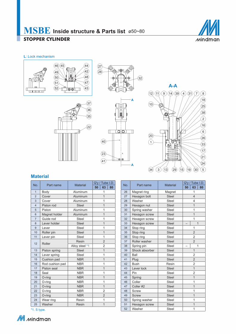
MSBE Inside structure & Parts list ø50~80
Material
No. Part name MaterialQ'y / Tube I.D.50 63 80
1 Body Aluminum 12 Cover Aluminum 13 Cover Aluminum 14 Piston rod Steel 15 Piston Aluminum 16 Magnet holder Aluminum 17 Guide rod Steel 18 Lever holder Steel 19 Lever Steel 1
10 Roller pin Steel 111 Lever pin Steel 1
12 RollerResin 2
Alloy steel *1 213 Piston spring Steel 114 Lever spring Steel 115 Cushion pad NBR 116 Rod cushion pad NBR 117 Piston seal NBR 118 Seal NBR 119 O-ring NBR 120 O-ring NBR 121 O-ring NBR 122 O-ring NBR 223 O-ring NBR 224 Wear ring Resin 125 Washer Resin 1
No. Part name MaterialQ'y / Tube I.D.50 63 80
26 Magnet ring Magnet 127 Hexagon bolt Steel 428 Washer Steel 429 Hexagon nut Steel 130 Spring washer Steel 131 Hexagon screw Steel 132 Hexagon screw Steel 133 Hexagon screw Steel – 134 Stop ring Steel 135 Stop ring Steel 236 Stop ring Steel 237 Roller washer Steel 238 Spring pin Steel – 139 Shock absorber Steel 140 Ball Steel 241 Plug Steel 242 Bush Resin 243 Lever lock Steel 144 Pin Steel 245 Spring Steel 146 Coller Steel 147 Coller #2 Steel 148 Screw Steel 149 Screw Steel 150 Spring washer Steel 151 Hexagon screw Steel 152 Washer Steel 1
32
37
4446 45
424948504751
4352
36
35
22
40
10
12 11 9 14 39 4 31 7 8
18
25
2
16
6
26
38
33
17
21
24
530
23
41
27
28
A
A
A-A
L: Lock mechanism
*1. S type.
53
46
67
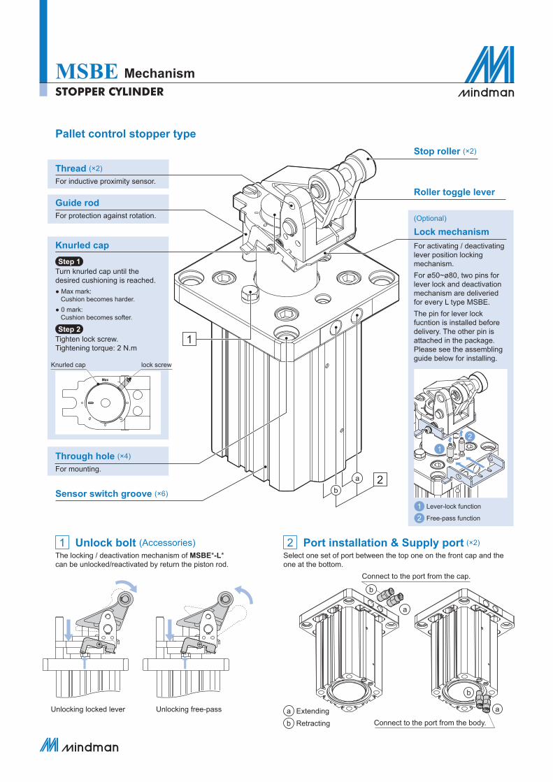
2×Rc1/8
2×Rc1/8
16
68
3.5
13.8
6
8
16
ø12
ø11
322
R25
13
31.4°
ø20
ø6.6
155.
35
5
81.3
5.2
MA
X1.
1
2×M
5×0.
5
76.1
(Con
veyo
r low
er li
mit)
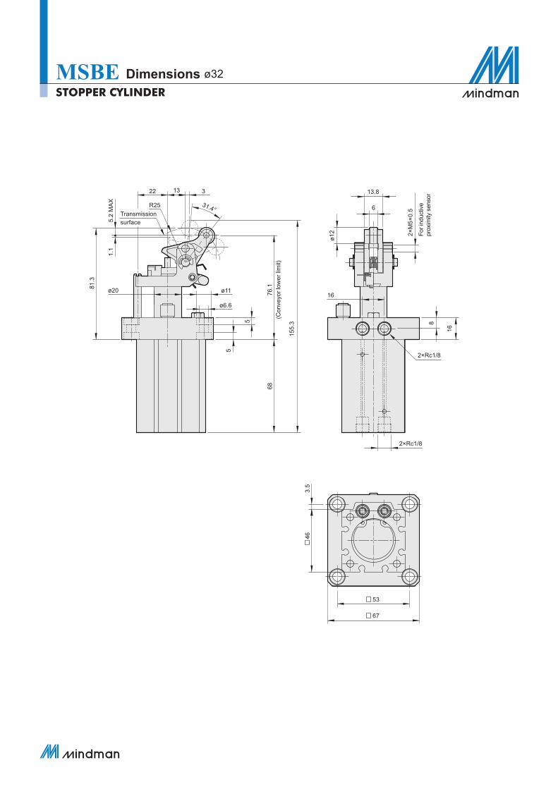
MSBE Dimensions ø32STOPPER CYLINDER
Transmissionsurface
For i
nduc
tive
prox
imity
sen
sor
L3 L1 L2 B3
B4 B5
B6
B7
B8
B2
B1
2×EE
2×E
B10
D2
D3
H4
H7
R1
øD1D6
T1
T1
H5
(Con
veyo
r low
er li
mit)
H6
H3
H1
D7
H8
MAX
H9
H2
W1
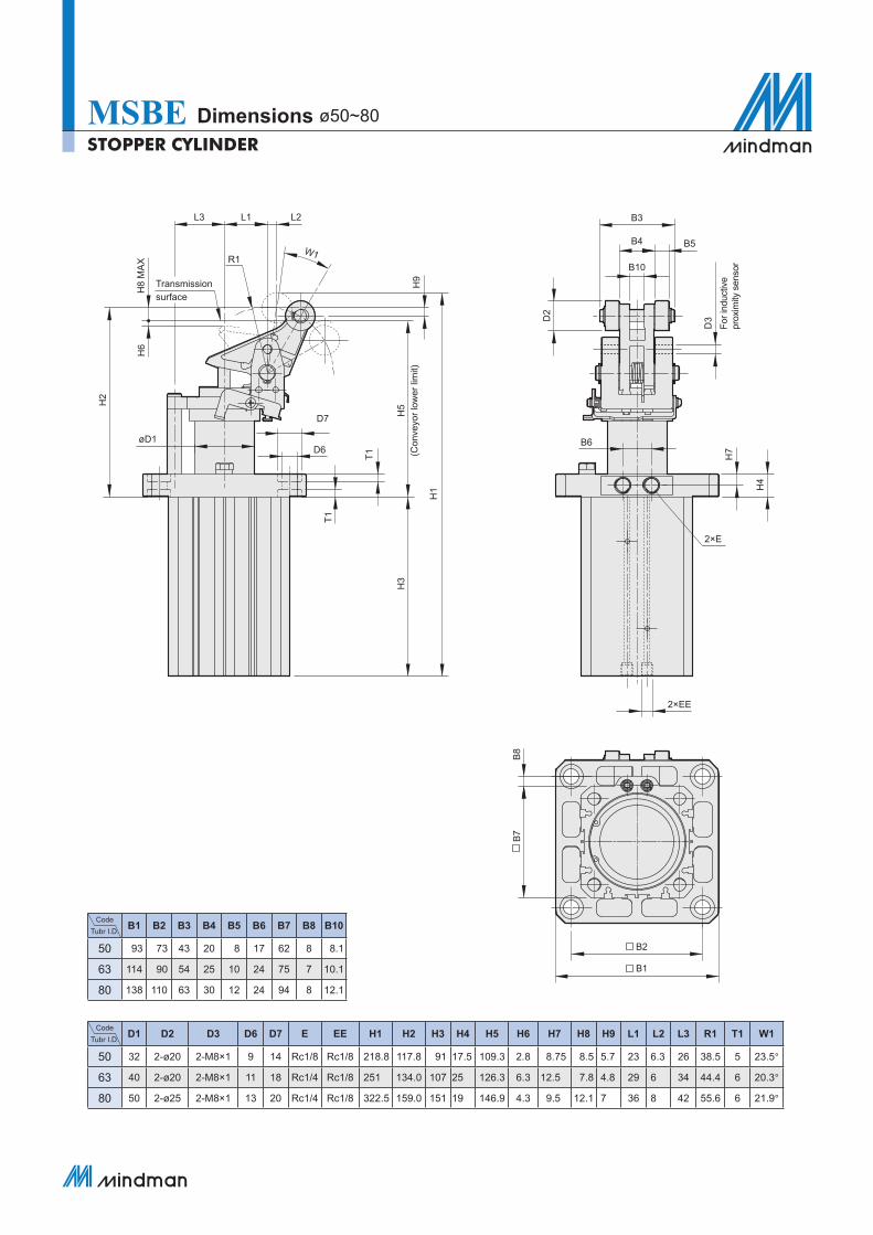
MSBE Dimensions ø50~80
CodeTubr I.D. D1 D2 D3 D6 D7 E EE H1 H2 H3 H4 H5 H6 H7 H8 H9 L1 L2 L3 R1 T1 W1
50 32 2-ø20 2-M8×1 9 14 Rc1/8 Rc1/8 218.8 117.8 91 17.5 109.3 2.8 8.75 8.5 5.7 23 6.3 26 38.5 5 23.5°
63 40 2-ø20 2-M8×1 11 18 Rc1/4 Rc1/8 251 134.0 107 25 126.3 6.3 12.5 7.8 4.8 29 6 34 44.4 6 20.3°
80 50 2-ø25 2-M8×1 13 20 Rc1/4 Rc1/8 322.5 159.0 151 19 146.9 4.3 9.5 12.1 7 36 8 42 55.6 6 21.9°
CodeTubr I.D. B1 B2 B3 B4 B5 B6 B7 B8 B10
50 93 73 43 20 8 17 62 8 8.1
63 114 90 54 25 10 24 75 7 10.1
80 138 110 63 30 12 24 94 8 12.1
STOPPER CYLINDER
Transmissionsurface
For i
nduc
tive
prox
imity
sen
sor