Embed Size (px)
Citation preview

ABSTRACT: Vibrations of chimneys under the wind action occur in-line with the wind as forced, random vibrations and cross-wind as vortex-induced vibrations. The former become important at extreme wind speeds, regular vortex shedding causes the latter and occurs at any wind speed. In the case of vortex resonance, when considerable vibration amplitudes develop, the structural displacements alter the fluid force, which is known as an aero-elastic coupling of force and structural response. Regarding the random load caused by turbulent wind, Davenport's pioneering concept of the gust response factor was applied to develop a simplified equivalent static load. Two different models are available regarding the design for vortex resonance. One is Ruscheweyh's approach to deal with vortex resonance as a forced vibration and to incorporate the aero-elastic effects in model parameters derived from experimental data. In the second model, the design for vortex resonance is based on Vickery & Basu's model of a self-limiting response process. The Eurocode contains both models but relies primarily on the first model. The new CICIND model code counts solely on the second approach. Experimental observations indicate the relative importance of parameters such as the Scruton number, the intensity of turbulence and the mode of vibration. Regarding the in-line wind load, the mechanical model also enters into the discussion. In some cases, the chimney dimensions indicate that a beam behaviour is neither realistic nor on the safe side. Then, a shell model has to be applied and the wind load cannot be considered as a force. Rather, pressures have to be utilized. The paper discusses the effect of these parameters and deals with the principal results concerning the along wind action and the design for vortex shedding.
KEY WORDS: Chimneys; gust wind load; vortex resonance; fatigue.
1 INTRODUCTION
Vibrations of chimneys under the wind action occur in the along-wind and in the across-wind direction.
Along-wind vibrations consist of a background, quasi-static contribution which reflects the stochastic and broad-band nature of the incoming flow. Depending on the natural frequency of the structure, a dynamic contribution due to resonance to turbulence may also arise.
Across-wind vibrations are due to the alternating vortex shedding in the wake. Vortex resonance occurs as the wind velocity approaches the critical value and, in case considerable vibration amplitudes develop so that the structural displacements alter the fluid force, aeroelastic forces may arise. Turbulence of the incoming flow also plays a role, both on the stationary cylinder, because it reduces the coherence of the lift force along the cylinder axis and widens the bandwidth of the lift spectrum, as well as on the vibrating cylinder.
All the design load models to account for along-wind vibrations are based on the gust response concept, originally developed by Davenport [1]. Essentially, it amplifies the mean wind force by applying the gust response factor G. The latter is a structural parameter which allows defining an equivalent static load, intended to reproduce the effects of the stochastic wind loading process on the most important structural stressing.
Two different models are available regarding the design for vortex resonance. They include the modeling of aeroelastic forces and ensure a self-limiting response cycle, which is the
distinctive feature of vortex excitation with respect to other aeroelastic phenomena. The two models differ in the manner they incorporate aeroelastic effects. One is Ruscheweyh's approach, which introduces the concept of the effective correlation length, whose value depends on the vibration level and is calculated by iteration. The model parameters are derived from experimental data. The other one is the Vickery&Basu model, which follows Scruton's approach [2] and treats the aeroelastic lift force as a component in out-of-phase with the motion, acting as a negative aerodynamic damping. The non-linear self-limiting behaviour of the response is treated by the Vickery&Basu model in a linearized manner, by introducing - as model parameters - the negative aerodynamic damping parameter for small amplitudes of oscillation and the self-limiting amplitude on the rms of the response.
The paper applies the design load models for the along wind action and for vortex resonance to two real samples of industrial chimneys (one is made of reinforced concrete and one is made of steel, see Table 1 and Table 2, respectively) and discusses the principal results.
Table 1. Geometry of sample chimney n.1 (concrete)
z [m] z/h r [m] t [m] 213.0 1.000 11.675 0.350 211.5 0.993 11.675 0.350 205.0 0.962 11.675 0.350 180.0 0.845 11.675 0.350 165.0 0.775 11.675 0.350
Vibrations of Chimneys under the Action of the Wind
Hans-Jürgen Niemann1, Francesca Lupi2, Rüdiger Hoeffer3
1Department of Civil and Environmental Engineering, Ruhr-Universität Bochum, D-44799 Bochum, Germany 2Department of Civil and Environmental Engineering, Università degli Studi di Firenze, 50139 Florence, Italy 3Department of Civil and Environmental Engineering, Ruhr-Universität Bochum, D-44799 Bochum, Germany
email: [email protected], [email protected], [email protected]
Proceedings of the 9th International Conference on Structural Dynamics, EURODYN 2014Porto, Portugal, 30 June - 2 July 2014
A. Cunha, E. Caetano, P. Ribeiro, G. Müller (eds.)ISSN: 2311-9020; ISBN: 978-972-752-165-4
1385

151.0 0.709 11.675 0.350 130.0 0.610 11.675 0.350 110.0 0.516 11.675 0.350 90.0 0.423 11.675 0.350 75.0 0.352 11.675 0.350 55.0 0.258 11.775 0.550 44.2 0.208 11.800 0.600 30.9 0.145 11.800 0.600 25.0 0.117 11.800 0.600 12.0 0.056 11.825 0.650 0.0 0.000 11.825 0.650
Table 2. Geometry of sample chimney n.2 (steel)
z [m] z/h r [m] t [m] 40.0 1.000 0.403 0.0063 17.0 0.425 0.403 0.0063 16.0 0.400 0.530 0.0063 0.0 0.000 0.530 0.0063
2 ALONG WIND ACTION
2.1 Design models for gust wind load
All gust wind models presently utilized in modern wind loading codes go back to the classical Davenport approach. It amplifies the mean wind force applying the gust response factor G. The wind force, given as a line load, is appropriate for slender, line-like structures such as chimneys:
w�z� = G ∙ w��z� (1)
In equation (1), z is the height above the ground; G is the gust response factor. The mean wind force wm(z) is based on the mean qm of the wind velocity pressure q(t), fluctuating in time:
w��z� = C�z� ∙ d�z� ∙ q��z� (2)
in which CD is the aerodynamic drag coefficient, d is the diameter of the chimney, qm(z) is the 10-min mean of the velocity pressure at level z. The mean wind force is a real physical quantity, whereas the wind force in equation (1) is an equivalent static load, intended to reproduce the effects of the stochastic wind loading process on the most important structural stressing.
To derive the gust response factor, Davenport [1] considered cantilevered, vertical structures and their response to the wind action, namely the mean (static) and time dependent (quasi-static and dynamic) components. He defined the gust response factor G as the ratio of the peak wind effect, Ep to the mean response, Em:
G = E�E� = E� + k�σ�E� = 1 + k� σ�E� (3)
where σE is the standard deviation (or rms-value) of the fluctuating response; kp is the peak factor, which is the ratio of the peak of the response fluctuation to its standard deviation, σE. The load fluctuations due to wind turbulence provide a broad band excitation of the structure. The rms response is split into resonant and quasi-static (background) components, σER and σEB, so that:
σ��E�� = σ���E�� + σ���E�� (4)
Davenport showed that both components are proportional to the intensity of turbulence Iv = σv/Vm if the structural behaviour is linear and the aerodynamic transmittance is quasi-stationary. Introducing factors R and B, the following expression for the gust response factor is obtained:
G = 1 + 2k�I��z���B� + R� (5)
with:
B = σ��E�12I� andR = σ��E�
12I�
(6)
In equation (5), zs is the height at which the reference flow parameters are utilized for determining G. The gust response factor is a structural, not a load parameter. In it, B takes into account the reduction of the load effect due to the non-simultaneous occurrence of the load peaks over the structural surface whereas R accounts for the amplification of the load effect due to resonance with wind turbulence. It depends on one hand on the wind flow parameters e.g. the mean wind profile, the turbulence intensity, and the integral length scales of the oncoming flow; it accounts on the other hand for structural parameters such as the size of the structure and its dynamic behaviour, in particular the lowest natural frequency, the related mode shape, and the damping.
Design wind load models in the Standard Codes are revisited applications of Davenport's approach.
In the Eurocode formulation, an important difference to the Davenport approach is that the Eurocode bases the wind force on the peak (or gust) velocity pressure qp. It is defined as the short-term maximum occurring within the 10-min interval of the extreme mean wind. The peak velocity pressure is the sum of the mean qm and the standard deviation σq amplified by the peak factor kq as in equation (7):
q��z� = q��z� + k!σ! (7)
q��z� = "1 + 7I��z�$ ρ&V��z�2
(8)
where Iv(z) is the turbulence intensity at height z. The transition from equation (7) to (8) involves two convenient approximations, namely (σq/qm) ≅ 2Iv and qm ≅ ρV²/2. Furthermore, the peak factor has been chosen as kq = 3.5. It corresponds to the gust wind speed in a 1-sec gust. It can be shown, that the exact value of equation (7) exceeds the approximation of equation (8) by a factor of {1 + (0.7Iv)
1.8}. The use of the profile of the peak velocity pressure (7) is
one of the merits of this model, because the profile of the wind force over the building height results in a more realistic image of the local gust loads at each level.
The Eurocode introduces the following formulation to express the wind force acting on a structure or a structural component:
w�z� = c��z��c)�z�� ∙ C ∙ A+,- ∙ q��z� (9)
Proceedings of the 9th International Conference on Structural Dynamics, EURODYN 2014
1386

where cs is the size factor covering the reduction of the load effect due to non-simultaneous gust peaks and cd accounts for resonant amplification of the gust effect. The dynamic factor is always > 1 in principle. However, it is close to 1 for stiff structures for which the resonant contribution R is much smaller than the background contribution B. The size factor cs is ≤ 1, it decreases as the loaded areas become larger. Their product is named structural factor and zs is the reference height for determining it.
By replacing in equation (9) the expressions of cs and cd given by the Eurocode, as well as the peak velocity pressure in equation (8), equation (10) is obtained. It clearly shows that the first term, close to 1, is the Eurocode modification to the Davenport approach.
w�z� = 1 + 7I��z�1 + 7I��z�� ∙ G ∙ρ&V��z�
2 ∙ C ∙ A+,- (10)
Other formulations are for example proposed in the CICIND model Code for industrial chimneys ([3], [4], [5], [6]). The CICIND wind load model (equation (11)) is unique in that it gives individual expressions for the mean wind load wm and the gust wind load wg, and their variation with respect to the height z above the ground:
w�z� = w��z� + w.�z� (11)
By separating both components, the gust load may be given any profile appropriate to reproduce the distribution of the real bending response due to gustiness. In particular, the CICIND adopts a linear profile with wg = 0 at z = 0, able to reproduce the peak bending moment at the base of the chimney. The values along the height may differ; furthermore the gust load profile does not account for variations of the diameter d and of the drag coefficient CD.
Further differences in the code stipulations concern the aerodynamic shape factor CD (termed cf in the Eurocode). For circular cross sections, the factor is particularly sensitive to the Reynolds number, the surface roughness, and the aspect ratio. Moreover, the three-dimensionality of the chimney and of the flow past it is responsible for the spanwise variation of the aerodynamic coefficient. The flow over the free end of the chimney reduces the wind force depending on the slenderness, however it locally increases in the tip region. The local increase of CD in the tip region of a chimney, the so-called tip effect, is not reflected in any of the codes.
Figure 1 shows the aerodynamic force coefficient distribution along the height applied to the chimney sample n.1, as derived by wind tunnel tests on a circular cylinder with a free-end (Lupi, [7]). It is compared to the distribution obtained by applying the CICIND Model Code and the Eurocode model to both a smooth concrete chimney surface (ks = 0.2 mm) and to a rough concrete chimney surface (ks = 1.0 mm).
Figure 2 shows the differences in the in-line wind loading profile due to different gust wind load models (Eurocode and CICIND load models, i.e. equations (9) and (11), respectively). The aforementioned superimposition in equation (11) of the mean load and the triangular gust load distribution is evident in the CICIND result. The label "EN-WT" stands for the Eurocode approach (9) applied to the non-uniform distribution of CD resulting from wind tunnel tests.
Figure 1. Aerodynamic force coefficients on the chimney sample n.1 after 1) wind tunnel tests (WT), application of the 2)
CICIND Model Code and 3) Eurocode (EN, with either smooth or rough surface)
Figure 2. In-line wind loading on the chimney sample n.1 according to different loading models and CD distributions: 1) Eurocode model applied to aerodynamic force coefficients
measured in the wind tunnel (EN-WT) and to those provided by the Code itself for 2) smooth or 3) rough cylinder surface
and 4) CICIND Model Code.
Figure 3. Bending moments on the sample chimney n.1 due different loading models
Figure 3 shows the resulting bending moment on the sample chimney n.1. Differences in the results are both due to different loading models and to the different distribution of aerodynamic coefficients, according to Figure 1. In fact, the accordance between the different models is good, despite the aforementioned differences in the gust load profiles. The differences in the response are predominantly due to the
0
0.1
0.2
0.3
0.4
0.5
0.6
0.7
0.8
0.9
1
0 0.1 0.2 0.3 0.4 0.5 0.6 0.7 0.8 0.9 1
z/h
CD
WT
CICIND
EN - smooth
EN - rough
0
0.1
0.2
0.3
0.4
0.5
0.6
0.7
0.8
0.9
1
0 5000 10000 15000 20000 25000 30000 35000 40000
z/h
Wind force [N/m]
EN - WT
EN - smooth
EN - rough
CICIND
0
0.1
0.2
0.3
0.4
0.5
0.6
0.7
0.8
0.9
1
0 100000 200000 300000 400000 500000 600000
z/h
Wind-induced bending moments [kNm]
EN - WT
EN - smooth
EN - rough
CICIND
Proceedings of the 9th International Conference on Structural Dynamics, EURODYN 2014
1387
different values and distributions of the aerodynamic coefficients.
On the basis of these and other results (see [8]), it can be concluded that, regarding the along wind action, the CICIND model code results in a simplified but conservative design. Even though the tip-effect is not included in the CICIND model, this is compensated by the relatively high and constant force coefficient. However, about 10% of reduction of stresses might be achieved through a more realistic distribution of aerodynamic coefficient, e.g. resulting from wind tunnel tests.
2.2 Structural behaviour: beam versus shell
In the chimney design, the wind loading may be represented by a wind force or by wind pressures non-uniformly distributed over the surface. Which way is appropriate depends on the slenderness of the chimney and the deformability of the circular cross-section. High slenderness and high ring stiffness of the wall imply a beam-like behaviour with cosine stress distribution along the circumference; then, wind forces are applicable. With thin wall and low aspect ratio the structure behaves as a shell. Then, the stresses due to wind concentrate at the windward side and pressure distributions are needed for the design calculations.
Figure 4. Meridional membrane stress n22 [kN/m] at different z/h levels, beam distribution at z = 0. Chimney sample n.1.
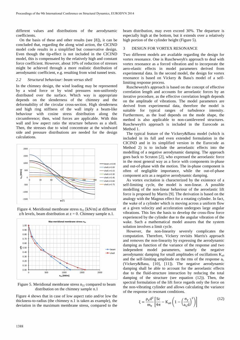
Figure 5. Meridional membrane stress n22 compared to beam distribution on the chimney sample n.1
Figure 4 shows that in case of low aspect ratio and/or low the thickness-to-radius (the chimney n.1 is taken as example), the deviation in the maximum membrane stress, compared to the
beam distribution, may even exceed 30%. The departure is especially high at the bottom, but it extends over a relatively high portion of the cylinder height (Figure 5).
3 DESIGN FOR VORTEX RESONANCE
Two different models are available regarding the design for vortex resonance. One is Ruscheweyh's approach to deal with vortex resonance as a forced vibration and to incorporate the aero-elastic effects in model parameters derived from experimental data. In the second model, the design for vortex resonance is based on Vickery & Basu's model of a self-limiting response process.
Ruscheweyh's approach is based on the concept of effective correlation length and accounts for aeroelastic forces by an iterative procedure, as the effective correlation length depends on the amplitude of vibrations. The model parameters are derived from experimental data, therefore the model is suitable for typical ranges of turbulence intensity. Furthermore, as the load depends on the mode shape, the method is also applicable to non-cantilevered structures. Ruscheweyh's approach is included in the Eurocode as Method 1.
The typical feature of the Vickery&Basu model (which is included in its full and even extended formulation in the CICIND and in its simplified version in the Eurocode as Method 2) is to include the aeroelastic effects into the modelling of a negative aerodynamic damping. The approach goes back to Scruton [2], who expressed the aeroelastic force in the most general way as a force with components in-phase and out-of-phase with the motion. The in-phase component is often of negligible importance, while the out-of-phase component acts as a negative aerodynamic damping.
As vortex excitation is characterized by the existence of a self-limiting cycle, the model is non-linear. A possible modelling of the non-linear behaviour of the aeroelastic lift force is proposed by Marris [9]. The derivation is based on the analogy with the Magnus effect for a rotating cylinder. In fact, the wake of a cylinder which is moving across a uniform flow at a given velocity and acceleration undergoes large angular vibrations. This lies the basis to develop the cross-flow force experienced by the cylinder due to the angular vibration of the wake. Such a mathematical model assures that the system solution involves a limit cycle.
However, the non-linearity severely complicates the computation. Therefore, Vickery revisits Marris's approach and removes the non-linearity by expressing the aerodynamic damping as function of the variance of the response and two independent model parameters, namely the negative aerodynamic damping for small amplitudes of oscillations Ka0 and the self-limiting amplitude on the rms of the response aL (Vickery&Basu, [10], [11]). The negative aerodynamic damping shall be able to account for the aeroelastic effects due to the fluid-structure interaction by reducing the total damping of the structure (see equation (12)). Then, the spectral formulation of the lift force regards only the force on the non-vibrating cylinder and allows calculating the variance of the response in resonant conditions.
ξ = ρ&d�m, 1Sc4π − K&7 81 − 9 σ:a;d<�=> (12)
-1500
-1000
-500
0
500
1000
1500
2000
0 30 60 90 120 150 180
n 22
[kN
/m]
φ [°]
beam z=0.00
shell z=0.00
shell z=0.15
shell z=0.30
shell z=0.45
shell z=0.60
shell z=0.75
0.00
0.10
0.20
0.30
0.40
0.50
0.60
0.70
0.80
0.90
1.00
0 500 1000 1500 2000
z/h
n22 [kN/m]
Max meridional membrane stress n22
beam
shell
Proceedings of the 9th International Conference on Structural Dynamics, EURODYN 2014
1388
An important parameter, which influences the size of the limiting amplitude of the response, is the mode shape. According to the Vickery&Basu approach, the limiting value is calibrated for the first mode of the cantilever structure. The CICIND Model Code for steel chimneys ([3], [5]) proposes a reduction of such a value for higher modes of vibrations, which depends only on the natural frequency of vibration and not on the shape of the mode. This issue, however, is not further investigated in this paper.
The Scruton number (Sc = 4πmξs/(ρD2)) governs the
amplitude of the response. The latter may lie in the lock-in range (high level of amplitude), in the transitional range or in the forced-vibration range (low level of amplitude). In particular, with regard to the Vickery&Basu model, the amplitude of oscillation is dictated by the ratio of the Scruton number Sc to the aerodynamic damping 4πKa. The response lies in the lock-in range when Sc << 4πKa. Physically, it means that the mechanical damping is much lower than the aerodynamic damping. In any case, the total damping of the structure will never become negative due to the existence, in the modeling, of the self-limiting cycle (see equation (12)). Small amplitudes of vibrations are instead predicted when Sc >> 4πKa.
The core of the Vickery&Basu model is then the modeling of the negative aerodynamic damping. Little information is available on that and the aerodynamic damping at least depends on the Reynolds number, the turbulence intensity, the mean wind velocity and the aspect ratio.
In smooth flow, the proneness of a chimney to experience vortex induced vibrations is primarily led by its Reynolds number at the critical velocity. As a general rule of thumb, in order to reduce the sensitivity of the chimney to vortex resonance, the low range of Re should be avoided. By looking at the CICIND recommendation, it can be estimated that Re > 5*105 would be advisable. This requirement can be translated in:
Re = V@+ ∙ dυ =fC ∙ dSt ∙ d
υ = fC ∙ d�St ∙ υ > 5 ∙ 10H
(13)
The kinematic viscosity of air ν is equal to 15*10-6 m2/s, therefore:
fC ∙ d�St > 152
(14)
if it assumed St = 0.2, it results:
fC ∙ d� > 1.5 (15)
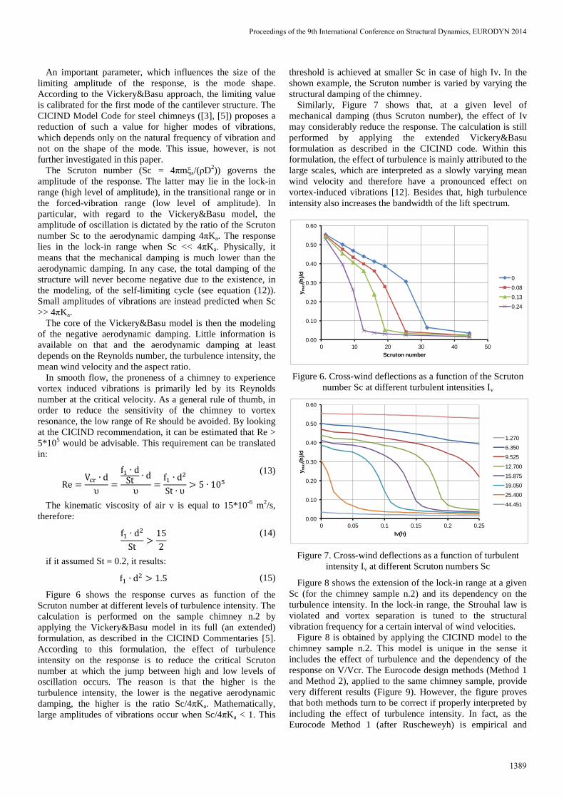
Figure 6 shows the response curves as function of the Scruton number at different levels of turbulence intensity. The calculation is performed on the sample chimney n.2 by applying the Vickery&Basu model in its full (an extended) formulation, as described in the CICIND Commentaries [5]. According to this formulation, the effect of turbulence intensity on the response is to reduce the critical Scruton number at which the jump between high and low levels of oscillation occurs. The reason is that the higher is the turbulence intensity, the lower is the negative aerodynamic damping, the higher is the ratio Sc/4πKa. Mathematically, large amplitudes of vibrations occur when Sc/4πKa < 1. This
threshold is achieved at smaller Sc in case of high Iv. In the shown example, the Scruton number is varied by varying the structural damping of the chimney.
Similarly, Figure 7 shows that, at a given level of mechanical damping (thus Scruton number), the effect of Iv may considerably reduce the response. The calculation is still performed by applying the extended Vickery&Basu formulation as described in the CICIND code. Within this formulation, the effect of turbulence is mainly attributed to the large scales, which are interpreted as a slowly varying mean wind velocity and therefore have a pronounced effect on vortex-induced vibrations [12]. Besides that, high turbulence intensity also increases the bandwidth of the lift spectrum.
Figure 6. Cross-wind deflections as a function of the Scruton number Sc at different turbulent intensities Iv
Figure 7. Cross-wind deflections as a function of turbulent intensity Iv at different Scruton numbers Sc
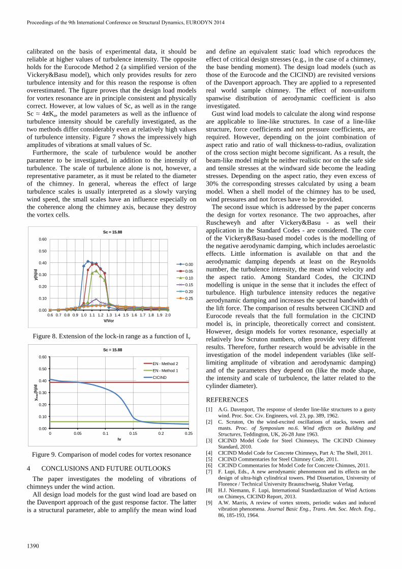
Figure 8 shows the extension of the lock-in range at a given Sc (for the chimney sample n.2) and its dependency on the turbulence intensity. In the lock-in range, the Strouhal law is violated and vortex separation is tuned to the structural vibration frequency for a certain interval of wind velocities.
Figure 8 is obtained by applying the CICIND model to the chimney sample n.2. This model is unique in the sense it includes the effect of turbulence and the dependency of the response on V/Vcr. The Eurocode design methods (Method 1 and Method 2), applied to the same chimney sample, provide very different results (Figure 9). However, the figure proves that both methods turn to be correct if properly interpreted by including the effect of turbulence intensity. In fact, as the Eurocode Method 1 (after Ruscheweyh) is empirical and
0.00
0.10
0.20
0.30
0.40
0.50
0.60
0 10 20 30 40 50
y max
(h)/
d
Scruton number
0
0.08
0.13
0.24
0.00
0.10
0.20
0.30
0.40
0.50
0.60
0 0.05 0.1 0.15 0.2 0.25
y max
(h)/
d
Iv(h)
1.270
6.350
9.525
12.700
15.875
19.050
25.400
44.451
Proceedings of the 9th International Conference on Structural Dynamics, EURODYN 2014
1389
calibrated on the basis of experimental data, it should be reliable at higher values of turbulence intensity. The opposite holds for the Eurocode Method 2 (a simplified version of the Vickery&Basu model), which only provides results for zero turbulence intensity and for this reason the response is often overestimated. The figure proves that the design load models for vortex resonance are in principle consistent and physically correct. However, at low values of Sc, as well as in the range Sc ≈ 4πKa, the model parameters as well as the influence of turbulence intensity should be carefully investigated, as the two methods differ considerably even at relatively high values of turbulence intensity. Figure 7 shows the impressively high amplitudes of vibrations at small values of Sc.
Furthermore, the scale of turbulence would be another parameter to be investigated, in addition to the intensity of turbulence. The scale of turbulence alone is not, however, a representative parameter, as it must be related to the diameter of the chimney. In general, whereas the effect of large turbulence scales is usually interpreted as a slowly varying wind speed, the small scales have an influence especially on the coherence along the chimney axis, because they destroy the vortex cells.
Figure 8. Extension of the lock-in range as a function of Iv
Figure 9. Comparison of model codes for vortex resonance
4 CONCLUSIONS AND FUTURE OUTLOOKS
The paper investigates the modeling of vibrations of chimneys under the wind action.
All design load models for the gust wind load are based on the Davenport approach of the gust response factor. The latter is a structural parameter, able to amplify the mean wind load
and define an equivalent static load which reproduces the effect of critical design stresses (e.g., in the case of a chimney, the base bending moment). The design load models (such as those of the Eurocode and the CICIND) are revisited versions of the Davenport approach. They are applied to a represented real world sample chimney. The effect of non-uniform spanwise distribution of aerodynamic coefficient is also investigated.
Gust wind load models to calculate the along wind response are applicable to line-like structures. In case of a line-like structure, force coefficients and not pressure coefficients, are required. However, depending on the joint combination of aspect ratio and ratio of wall thickness-to-radius, ovalization of the cross section might become significant. As a result, the beam-like model might be neither realistic nor on the safe side and tensile stresses at the windward side become the leading stresses. Depending on the aspect ratio, they even excess of 30% the corresponding stresses calculated by using a beam model. When a shell model of the chimney has to be used, wind pressures and not forces have to be provided.
The second issue which is addressed by the paper concerns the design for vortex resonance. The two approaches, after Ruscheweyh and after Vickery&Basu - as well their application in the Standard Codes - are considered. The core of the Vickery&Basu-based model codes is the modelling of the negative aerodynamic damping, which includes aeroelastic effects. Little information is available on that and the aerodynamic damping depends at least on the Reynolds number, the turbulence intensity, the mean wind velocity and the aspect ratio. Among Standard Codes, the CICIND modelling is unique in the sense that it includes the effect of turbulence. High turbulence intensity reduces the negative aerodynamic damping and increases the spectral bandwidth of the lift force. The comparison of results between CICIND and Eurocode reveals that the full formulation in the CICIND model is, in principle, theoretically correct and consistent. However, design models for vortex resonance, especially at relatively low Scruton numbers, often provide very different results. Therefore, further research would be advisable in the investigation of the model independent variables (like self-limiting amplitude of vibration and aerodynamic damping) and of the parameters they depend on (like the mode shape, the intensity and scale of turbulence, the latter related to the cylinder diameter).
REFERENCES [1] A.G. Davenport, The response of slender line-like structures to a gusty
wind. Proc. Soc. Civ. Engineers, vol. 23, pp. 389, 1962. [2] C. Scruton, On the wind-excited oscillations of stacks, towers and
masts. Proc. of Symposium no.6. Wind effects on Building and Structures, Teddington, UK, 26-28 June 1963.
[3] CICIND Model Code for Steel Chimneys, The CICIND Chimney Standard, 2010.
[4] CICIND Model Code for Concrete Chimneys, Part A: The Shell, 2011. [5] CICIND Commentaries for Steel Chimney Code, 2011. [6] CICIND Commentaries for Model Code for Concrete Chimnes, 2011. [7] F. Lupi, Eds., A new aerodynamic phenomenon and its effects on the
design of ultra-high cylindrical towers. Phd Dissertation, University of Florence / Technical University Braunschweig, Shaker Verlag.
[8] H.J. Niemann, F. Lupi, International Standardizazion of Wind Actions on Chimeys, CICIND Report, 2013.
[9] A.W. Marris, A review of vortex streets, periodic wakes and induced vibration phenomena. Journal Basic Eng., Trans. Am. Soc. Mech. Eng., 86, 185-193, 1964.
0.00
0.10
0.20
0.30
0.40
0.50
0.60
0.6 0.7 0.8 0.9 1.0 1.1 1.2 1.3 1.4 1.5 1.6 1.7 1.8 1.9 2.0
y(h)
/d
V/Vcr
Sc = 15.88
0.00
0.05
0.10
0.15
0.20
0.25
0.00
0.10
0.20
0.30
0.40
0.50
0.60
0 0.05 0.1 0.15 0.2 0.25
y max
(h)/
d
Iv
Sc = 15.88
EN - Method 2
EN - Method 1
CICIND
Proceedings of the 9th International Conference on Structural Dynamics, EURODYN 2014
1390

[10] B.J. Vickery, R.I. Basu, Across-wind vibrations of structures of circular cross-section. Part II: Development of a mathematical model for two-dimensional conditions. Journal of Wind Engineering and Industrial Aerodynamics, Vol. 12, 49–73, 1983.
[11] B.J. Vickery, R.I. Basu, Across-wind vibrations of structures of circular cross-section. Part 1: Development of a mathematical model for full-scale application. Journal of Wind Engineering and Industrial Aerodynamics, Vol. 12, 75–97, 1983.
[12] S.O. Hansen, Vortex-induced vibrations of line-like structures. CICIND Report, Vol. 15, No 1, 15-23, 1998.
Proceedings of the 9th International Conference on Structural Dynamics, EURODYN 2014
1391


![[BS en 13084-2-2007] -- Free-standing Chimneys. Concrete Chimneys](https://img.pdfslide.us/doc/110x75/577c7e1f1a28abe054a09ebb/bs-en-13084-2-2007-free-standing-chimneys-concrete-chimneys.jpg)