Embed Size (px)
Citation preview
Politecnico di MilanoFacoltà di Ingegneria dell’Informazione
MRN – 10 – LTE
Mobile Radio NetworksProf. Antonio Capone
Outline
1. Introduction2. Network Architecture3. Radio Interface
1. Introduction
© All rights reserved - copy forbidden - L. Dell'Anna/A. Capone 3
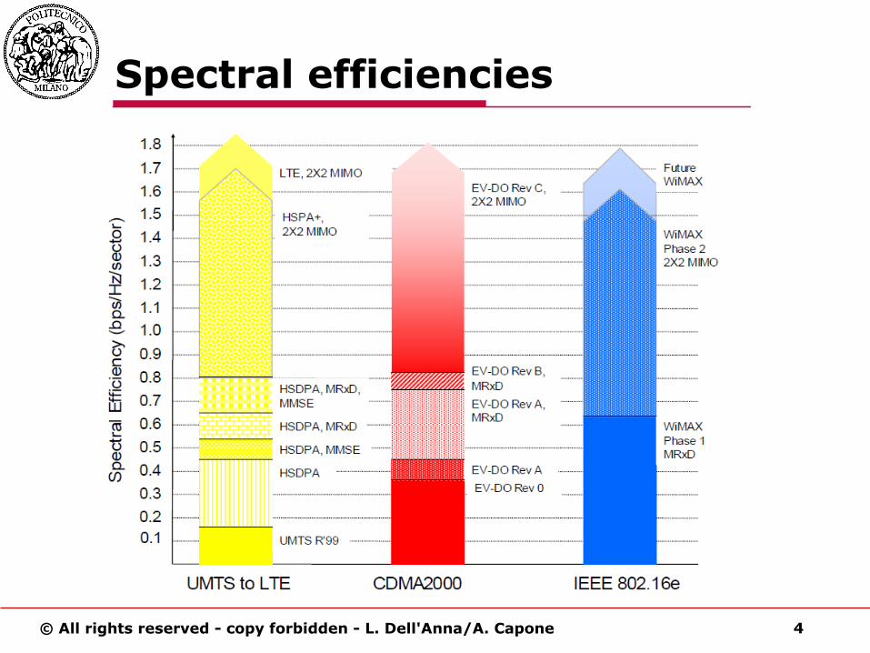
Spectral efficiencies
© All rights reserved - copy forbidden - L. Dell'Anna/A. Capone 4
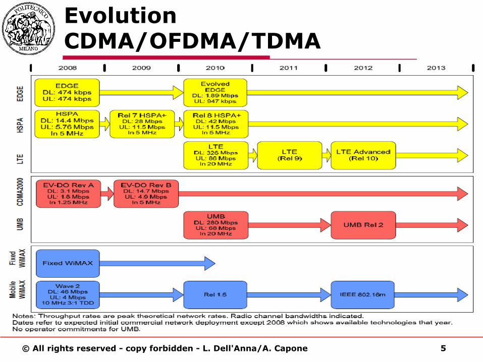
Evolution CDMA/OFDMA/TDMA
© All rights reserved - copy forbidden - L. Dell'Anna/A. Capone 5
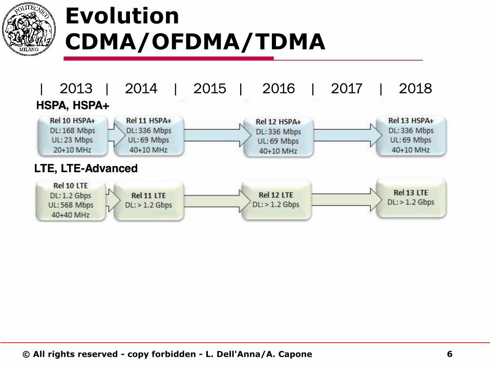
Evolution CDMA/OFDMA/TDMA
© All rights reserved - copy forbidden - L. Dell'Anna/A. Capone 6
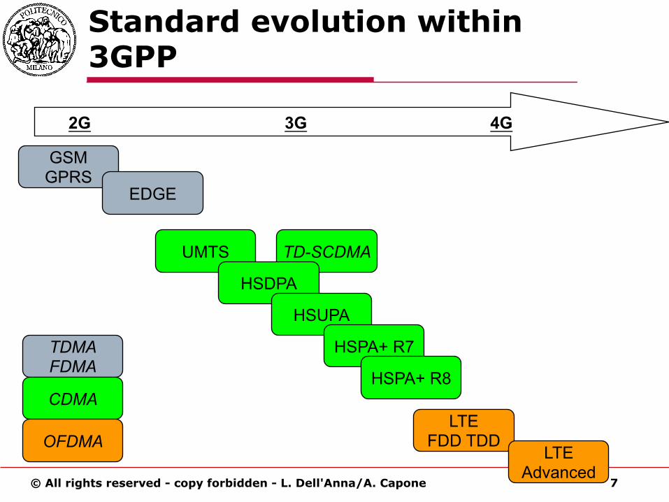
Standard evolution within 3GPP
GSMGPRS
EDGE
UMTS TD-SCDMA
HSDPA
HSUPA
HSPA+ R7
HSPA+ R8
LTEFDD TDD
LTEAdvanced
2G 3G 4G
TDMAFDMA
CDMA
OFDMA
© All rights reserved - copy forbidden - L. Dell'Anna/A. Capone 7
Voice services on LTE
o No support to circuit switched services in LTE
o But SMS and Voice are the main source of revenues for operators
o Possible approachesn LTE only for data (no voice)n Fallback on 2G/3Gn Voice over LTE via Generic Access (VoLGA)n Voice over IMS & One Voice Profilen Over-the-Top VoIP
© All rights reserved - copy forbidden - L. Dell'Anna/A. Capone 8
LTE – Performance targetso Peak data rate
n 100 Mbps DL / 50 Mbps UL per sector in a 20 MHz band
o 200+ active users per cell (5 MHz)o Latency in the user-plane <5 mso Maximum coverage distance 100 Kmo Mobility
n Optimized for 0-15 km/hn High performance for 15/120 km/hn Support for high speed up to 350 km/h
o Multimedia broadcast services (E-MBMS)o Flexible spectrum usage: 1.4 - 20 MHzo Advanced end-to-end QoS support
© All rights reserved - copy forbidden - L. Dell'Anna/A. Capone 9
LTE - Technologies
o Multiple accessn DL: OFDMA with Cyclic Prefix (CP)n UL: Single Carrier FDMA (SC-FDMA) with CP
o Adaptive modulation and channel codingn DL/UL: QPSK, 16QAM e 64QAMn Convolutional coding and turbo coding (Rel-6)
o Advance MxN MIMO techniques n (2/4)x(2/4) downlink e uplink n Multi-user MIMO
o FDD and TDD supporto H-ARQ, rate control, security, etc.
© All rights reserved - copy forbidden - L. Dell'Anna/A. Capone 10
2. Network Architecture
© All rights reserved - copy forbidden - L. Dell'Anna/A. Capone 11
EPS (3GPP 4G) = SAE (EPS) + LTE (eUTRAN)
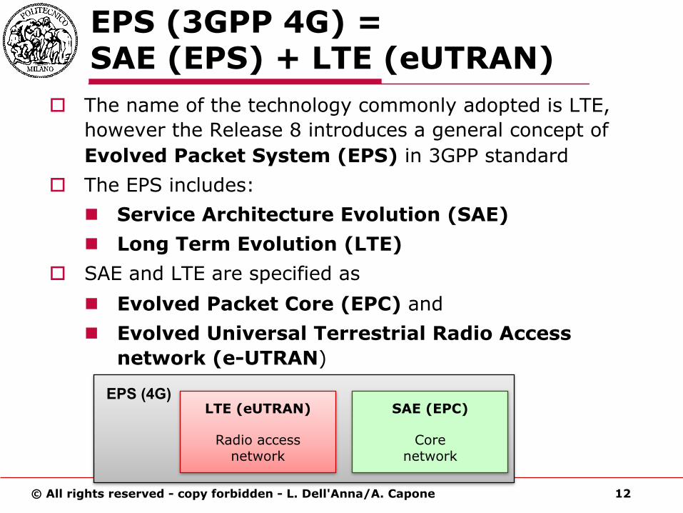
o The name of the technology commonly adopted is LTE, however the Release 8 introduces a general concept of Evolved Packet System (EPS) in 3GPP standard
o The EPS includes:n Service Architecture Evolution (SAE) n Long Term Evolution (LTE)
o SAE and LTE are specified asn Evolved Packet Core (EPC) andn Evolved Universal Terrestrial Radio Access
network (e-UTRAN)
EPS (4G)LTE (eUTRAN)
Radio access network
SAE (EPC)
Corenetwork
© All rights reserved - copy forbidden - L. Dell'Anna/A. Capone 12
EPS architecture
o System is completely redesigned according to the “All-IP” paradigm
o New concept of “flat network”o The access network includes only a single
device: eNodeB (LTE base stations)o New advanced protocol stackso Open interfaces and high interoperabilityo Advanced O&Mo SON (Self Organizing Network) for
autoconfiguration of eNodeB (eNB)© All rights reserved - copy forbidden - L. Dell'Anna/A. Capone 13
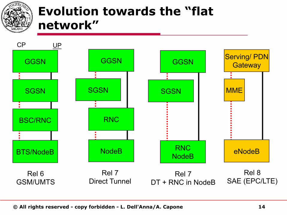
Evolution towards the “flat network”
UPCP
GGSN
SGSN
BSC/RNC
BTS/NodeB
Rel 6GSM/UMTS
Serving/ PDNGateway
MME
eNodeB
Rel 8SAE (EPC/LTE)
GGSN
SGSN
RNC
NodeB
Rel 7Direct Tunnel
GGSN
SGSN
RNCNodeB
Rel 7DT + RNC in NodeB
© All rights reserved - copy forbidden - L. Dell'Anna/A. Capone 14
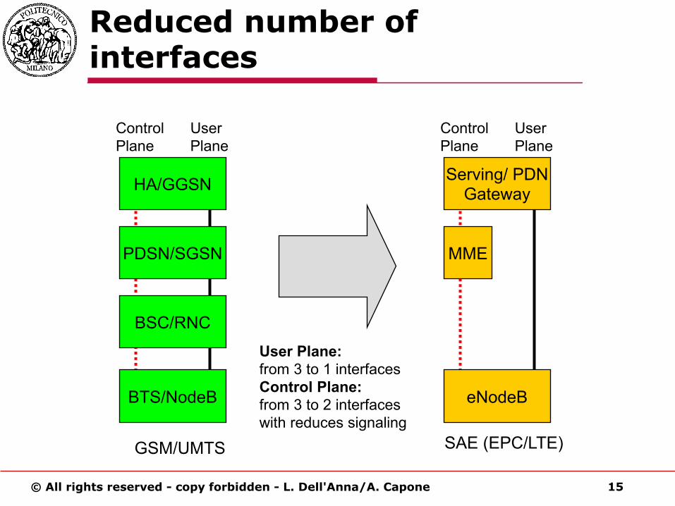
Reduced number of interfaces
HA/GGSN
PDSN/SGSN
BSC/RNC
BTS/NodeB
ControlPlane
UserPlane
Serving/ PDNGateway
MME
eNodeB
ControlPlane
UserPlane
GSM/UMTS SAE (EPC/LTE)
User Plane: from 3 to 1 interfacesControl Plane: from 3 to 2 interfaces with reduces signaling
© All rights reserved - copy forbidden - L. Dell'Anna/A. Capone 15
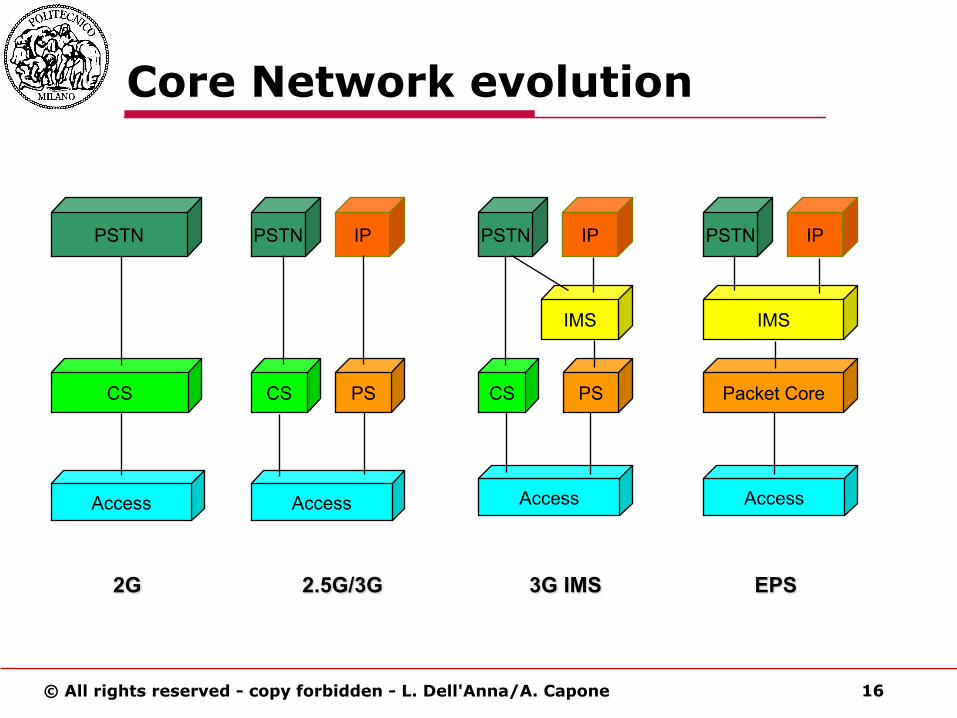
Core Network evolution
Access Access Access
CS
Access
PSCS CS Packet CorePS
PSTN PSTN IP
IMS
PSTN IP
IMS
PSTN IP
2G 2.5G/3G 3G IMS EPS
© All rights reserved - copy forbidden - L. Dell'Anna/A. Capone 16
SAE - Evolved Packet Core
o It’s a Core Network completely based on IP that can serve access networks with different technologiesn 3GPP (LTE, UMTS, GSM/EDGE)n Non-3GPP (WLAN, WiMAX)n Fixed (Ethernet, DSL, optical fiber)
o That can providen Mobility (including handover between different
systems)n Policy management (e.g. unique charging)n Security
© All rights reserved - copy forbidden - L. Dell'Anna/A. Capone 17
SAE - Evolved Packet Core
o It has a flat architecture with only two nodesn Base station (evolved-NodeB) n Gateway (Serving/PDN GW)
o It provides high performance and reduced operational costs
o With respect to 3G architecture, RNC functionalities are moved into the eNodeB
o The handover management is completely provided by base stations
o All interfaces are based on IP
© All rights reserved - copy forbidden - L. Dell'Anna/A. Capone 18
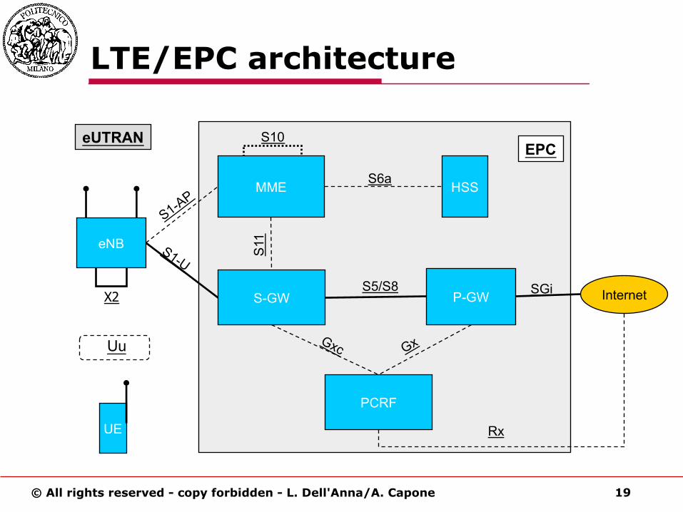
LTE/EPC architecture
P-GWS-GW Internet
eNB
HSS
PCRF
S11
S6a
S5/S8 SGi
EPC
Rx
eUTRAN
X2
MME
S10
UE
Uu
© All rights reserved - copy forbidden - L. Dell'Anna/A. Capone 19
LTE/EPC architecture
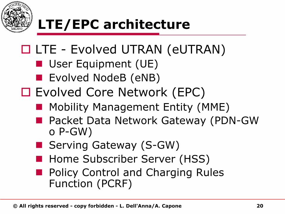
o LTE - Evolved UTRAN (eUTRAN)n User Equipment (UE)n Evolved NodeB (eNB)
o Evolved Core Network (EPC)n Mobility Management Entity (MME)n Packet Data Network Gateway (PDN-GW
o P-GW)n Serving Gateway (S-GW)n Home Subscriber Server (HSS)n Policy Control and Charging Rules
Function (PCRF)
© All rights reserved - copy forbidden - L. Dell'Anna/A. Capone 20
LTE - E-UTRAN
MME/S-GW MME/S-GW
eNB
eNB
eNB
S1
S1 S1
S1
X2
X2
X2X2
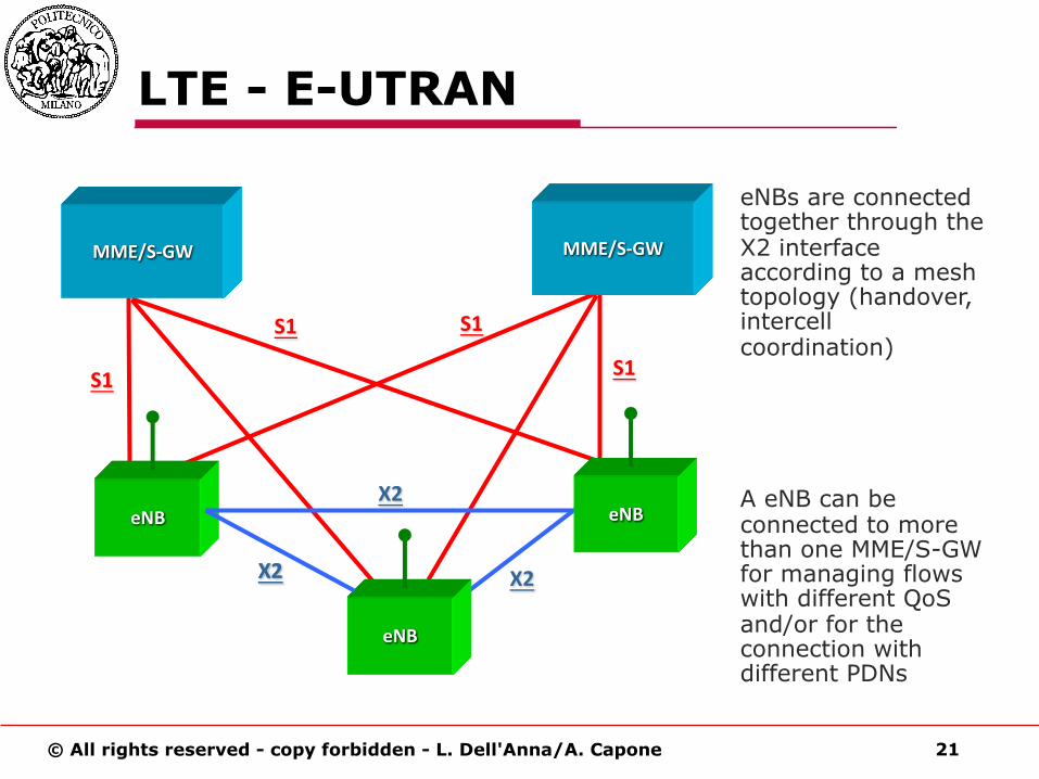
eNBs are connected together through the X2 interface according to a mesh topology (handover, intercellcoordination)
A eNB can be connected to more than one MME/S-GW for managing flows with different QoSand/or for the connection with different PDNs
© All rights reserved - copy forbidden - L. Dell'Anna/A. Capone 21
User Equipment (UE)
o Handheld, smartphone, USB-card, sensors, etc.o It includes
n UICC (Universal Integrated Circuit Card) with the USIM (Universal Subscriber Identity Module)
n TE (Terminal Equipment)
o It will include also a VoIP client for LTE voice calls
o It can have multiple antennas for MIMO supporto Most of UE will be multi standard: GSM, HSPA e
LTE (FDD o TDD)
© All rights reserved - copy forbidden - L. Dell'Anna/A. Capone 22
eNB – Evolved Node Bo It’s the base station of eUTRAN, which
manages one or more cellso With respect to GSM and UMTS it also performs
additional functions (that were performed by BSC and RNC) like for instance handover
o All radio protocols are terminated on the eNB for for IP connectivity the eNB acts as relay towards the EPC (layer 2 bridge)
o The eNB manages radio resources and mobilityo The eNB is connected to a set of MME/S-GWs,
even if each UE is connected to only one of these
© All rights reserved - copy forbidden - L. Dell'Anna/A. Capone 23
eNB – Evolved Node Bo Main functions
n Radio Resource Management: Radio Bearer Control, Radio Admission Control, Connection Mobility Control, Scheduling in UL and DL)
n IP header compression and data flow encryption
n MME selection in case of request from UEn Routing of User Plane data towards the
Serving Gatewayn Scheduling and transmission of
o Paging messages (originated by MME)o broadcast (originated by MME or O&M)
n Measurements for mobility and scheduling© All rights reserved - copy forbidden - L. Dell'Anna/A. Capone 24
MME - Mobility Management Entity
o It’s the main node of the Core Network SAE/LTE
o It includes most of the functions that in 2G/3G networks where implemented in different nodes
o It is involved in the Control Plane onlyo It establishes a direct connection with the UEo It is connected simultaneously with several
UEs, eNBs, MMEs (even of different operators), S-GWs, and HSSs
© All rights reserved - copy forbidden - L. Dell'Anna/A. Capone 25
MME - Mobility Management Entity
o Authentication and Securityn Together with the HSS it manages
authentication and encryption of channels for CP and UP
o Mobility Managementn It asks eNB and S-GW to allocate resources
for UE when they register to the networkn It stores the Tracking Area (or the eNB if in
active mode) that UE communicates periodically
n It is involved in handover procedures together with eNB, S-GW and other MME
© All rights reserved - copy forbidden - L. Dell'Anna/A. Capone 26
MME - Mobility Management Entity
o User Profile Management and Service Connectivityn It provides the basic connectivity for the initial
exchange of messages between UE and network (default bearer)
n It selects the Packet Data Network to be assigned to each UE
n When requested by the network (S-GW) or UE, it establishes a new bearer (dedicated)
n The MME verifies the profile and services for the UE before allocating the bearer
© All rights reserved - copy forbidden - L. Dell'Anna/A. Capone 27
S-GW – Serving Gatewayo The S-GW is in charge of managing the tunnel of UP
protocols and switching the tunnel in case of mobilityo The S-WG manages its own resources based on requests
from MME, P-GW and PCRFo It’s the “anchor” node for terminals moving between
different eNodeB. When requested by the MME, the S-GW reroutes data flows between the eNBs involved in a handover
o In case of inter-S-GW handover, the MME deletes the IP tunnel from old S-GW and establishes a tunnel with the new S-GW
o When the P-GW sends packets to a UE in IDLE, the S-GW buffers packets and requests to MME to perform the paging procedure
o The S-GW stores traffic statistics and it is involved in the interworking with other 3GPP systems, like GSM e UMTS
© All rights reserved - copy forbidden - L. Dell'Anna/A. Capone 28
S-GW – Serving Gateway
o Functionsn Mobility anchor point for the inter-eNB handovern Mobility anchoring for inter-3GPP mobilityn Data buffering in downlink for idle UEn Service instantiation for requests from the
networkn Routing and packet forwarding n Packet tagging at transport layer in uplink and
downlinkn Charging in UL and DL UE, PDN, and QCI
© All rights reserved - copy forbidden - L. Dell'Anna/A. Capone 29
P-GW – PDN Gateway
o The P-GW manages IP addresses for UEs (IPv4/IPv6, DHCP)
o Together with the PCRF, it controls QoS and charging based on traffic flow
o Through the PCEF (a component of the P-GW), it filters IP traffic and calculate statistical information
o The P-GW allows the interworking with non-3GPP packet technologies like WiMAX and WLAN
© All rights reserved - copy forbidden - L. Dell'Anna/A. Capone 30
P-GW – PDN Gateway
o Functionsn Mapping of IP flows and GTP tunnelsn Packet filtering per single UEn Traffic interception n IP address allocation for UEn Charging based on active services in UL
and DL n Data rate control in Downlink
© All rights reserved - copy forbidden - L. Dell'Anna/A. Capone 31
PCRF (Policy and Charging Rules Function)
o To each connection UE-PDN is associated a PCRF
o The PCRF implements the Policy and Charging Control (PCC)
o It authorizes the assignment of QoS profiles to flows to/from UEs
o Together with the PCEF, it manages charging based on traffic flow
© All rights reserved - copy forbidden - L. Dell'Anna/A. Capone 32
HSS (Home Subscriber Server)
o The HSS stores permanent user profileso It manages authentication (AuC) in its
network and in the Visited PLMNo It is connected to all MME of the
networko It stores the UE position and the
information on the associated MMEo It is basically the evolution of the
HLR/AUC used by GSM and UMTS
© All rights reserved - copy forbidden - L. Dell'Anna/A. Capone 33
Services Domain
o The Service Domain includes all the other system components that are not part of LTE technology but that are used for basic services (like e.g. VoIP)
o Some service domain platforms are standard like the IMS, while other are just Internet application server
o In the case IMS, the integration is based on 3GPP specifications. In other cases it is managed by operators independently (web-servers, P2P ntw, etc.)
© All rights reserved - copy forbidden - L. Dell'Anna/A. Capone 34
IP Multimedia Sub-system (IMS)
o The IMS is a system that allows mobile operators to offers multimedia services through Internet platforms
o The IMS implements for mobile users the convergence of voice, video, instant messaging, web applications, etc.
o It combines the growth of Internet applications and services with the global diffusion of the mobile access
© All rights reserved - copy forbidden - L. Dell'Anna/A. Capone 35
IP Multimedia Sub-system (IMS)
o With the introduction of the IMS, 3GPP systems tend to comply with Internet IEFT standards
o SIP in particular, the main signaling protocol of the IMS, is actually specified by the IEFT
o Through the IMS, mobile operators try to offer value added services and not just “dumb pipe” of bits
o In 4G systems, voice services are provided through the IMS
© All rights reserved - copy forbidden - L. Dell'Anna/A. Capone 36
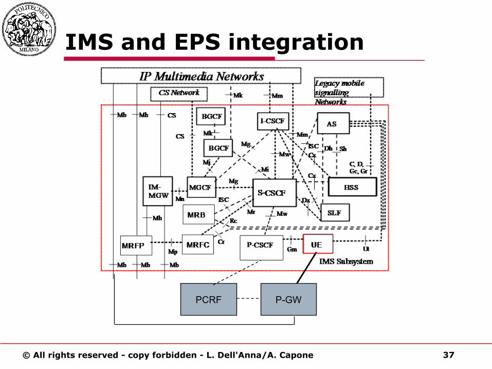
IMS and EPS integration
PCRF P-GW
© All rights reserved - copy forbidden - L. Dell'Anna/A. Capone 37
2.1 Interfaces and protocols
© All rights reserved - copy forbidden - L. Dell'Anna/A. Capone 38
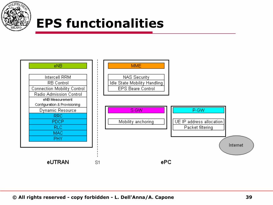
EPS functionalities
© All rights reserved - copy forbidden - L. Dell'Anna/A. Capone 39
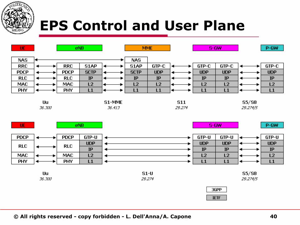
EPS Control and User Plane
© All rights reserved - copy forbidden - L. Dell'Anna/A. Capone 40
Layer NAS (Non Access Stratum)
o Direct UE-MME connection which does not involves the eNBo It includes two sub layers
n EMM (EPS Mobility Management)o Attach/Detach, Tracking Area Update (UE in Idle
Mode), Transition Idle-Connected per Service Request (from UE), Paging Request (from network), Authentication, Encryption, Security
n ESM (EPS Session Management)o Activation and management of new bearers
© All rights reserved - copy forbidden - L. Dell'Anna/A. Capone 41
LTE-Uu protocolso RRC (Radio Resource Control)
n Management of radio resources, signaling, data connections, and handover
o PDCP (Packet Data Convergence Pr.)n UP: IP Header Compressionn CP: Encryption e Integrity
o RLC (Radio Link Control)n Segmentation and concatenation of PDCP PDUs. Error
correction and ARQ (Automatic Repeat Request)o MAC (Medium Access Control)
n Scheduling based on priority, multiplexing and HARQ (Hybrid ARQ)
o PHY (Physical Layer)n Modulation, coding
© All rights reserved - copy forbidden - L. Dell'Anna/A. Capone 42
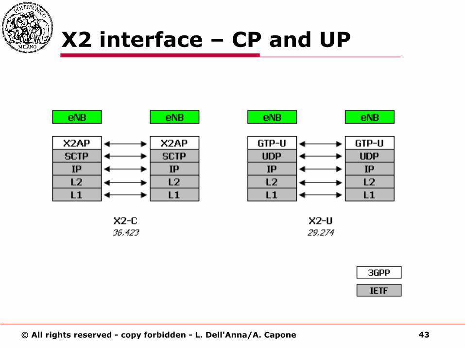
X2 interface – CP and UP
© All rights reserved - copy forbidden - L. Dell'Anna/A. Capone 43
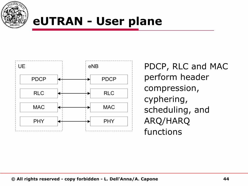
eUTRAN - User plane
PDCP, RLC and MAC perform header compression, cyphering, scheduling, and ARQ/HARQ functions
eNB
PHY
UE
PHY
MAC
RLC
MAC
PDCPPDCP
RLC
© All rights reserved - copy forbidden - L. Dell'Anna/A. Capone 44
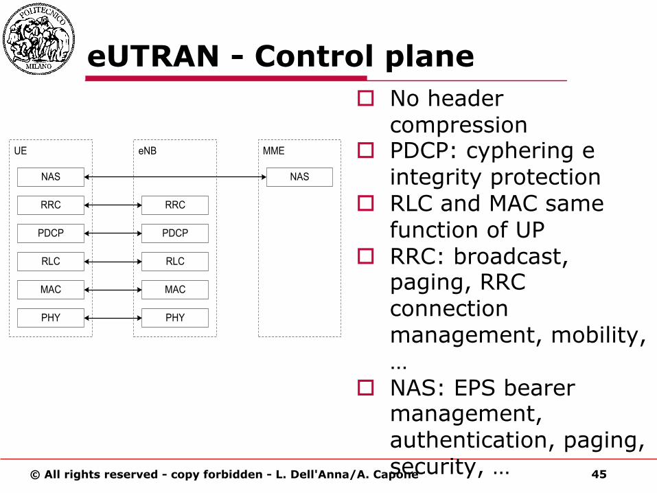
eUTRAN - Control planeo No header
compressiono PDCP: cyphering e
integrity protectiono RLC and MAC same
function of UPo RRC: broadcast,
paging, RRC connection management, mobility, …
o NAS: EPS bearer management, authentication, paging, security, …
eNB
PHY
UE
PHY
MAC
RLC
MAC
MME
RLC
NAS NAS
RRC RRC
PDCP PDCP
© All rights reserved - copy forbidden - L. Dell'Anna/A. Capone 45
S1 interface
o S1 interface connects the eNodeB to the Evolved Packet Core (EPC) and includes User Plane and Control Plane
o S1 is a all-IP interface, without support for the old SS7 protocols
o The S1 is part of the SON (Self Organizing Networks) which allow automatic configuration of network parameters
© All rights reserved - copy forbidden - L. Dell'Anna/A. Capone 46
S1 interface - Control Plane
o It is based on the SCTP/IP (Stream Control Transmission Protocol/IP) stack from which it inherits robustness in message transport
o The SCTP/IP allows the use of multiple streams for adding redundancy to signaling flows and multi-homing
o In LTE, the S1-AP (Application Protocol) is directly on top of the SCTP without any intermediate protocol for Connection Management
o The use of IP layers is completely free and can also be based on the traditional IPv4, even if IPv6 will probably be most common
© All rights reserved - copy forbidden - L. Dell'Anna/A. Capone 47
S1 interface – User Plane
o It is based on the GTP/UDP/IP stack already used in UMTS
o The GTP-U (GTP User plane) facilitates the tunnel management between different 3GPP systems
o IP is not specifiedo The transport bearer is identifies through
n Source GTP TEID (Tunneling End ID)n Destination GTP TEIDn Source IP addressn Destination IP address
© All rights reserved - copy forbidden - L. Dell'Anna/A. Capone 48
X2 interface
o Interconnects directly different eNodeBs. All eNodeBs that have adjacent radio coverage should be connected in mesh mode
o X2 and S1 protocols stacks are similar, except for the X2-AP and l’S1-AP
o X2 interface has an important role during handover since it forward downlink traffic towards the new eNB until the new data connection is established (in the Uplink it is the UE itself that sends traffic to the new eNB)
© All rights reserved - copy forbidden - L. Dell'Anna/A. Capone 49
2.2 Self Organizing Networks
© All rights reserved - copy forbidden - L. Dell'Anna/A. Capone 50
Self Organizing Networks
o Network configuration and management are complex and costly tasks for mobile operators
o Several problems can be caused by human mistakes
o SON has the goal of making network auto configuring
o The introduction of LTE makes things even more difficult:n Coexisting 2G/3G/LTE networksn A large number of eNBs (including Home eNB and
femto cells)n Large number of network parameters n …
© All rights reserved - copy forbidden - L. Dell'Anna/A. Capone 51
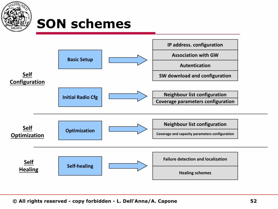
SON schemes
BasicSetup
Optimization
Self-healing
InitialRadioCfg
IPaddress.configuration
AssociationwithGW
Autentication
SWdownloadandconfiguration
NeighbourlistconfigurationCoverageparametersconfiguration
Neighbourlistconfiguration
Coverageandcapacityparametersconfiguration
Failuredetectionandlocalization
Healingschemes
SelfConfiguration
SelfOptimization
SelfHealing
© All rights reserved - copy forbidden - L. Dell'Anna/A. Capone 52

Self planning and configuration
o New installed eNodeBs connect to configuration server and provides their HW and SW profile.
o After an authentication phase, configuration parameters for creating S1 and X2 connection are downloaded and applied.
o At the end of the procedure the eNodeB becomes fully operative
o Initial configuration of transport networko Authenticationo Association to O&M servero Download of basic SW and parameterso Radio configuration
o Result: fast and cheap system rollout© All rights reserved - copy forbidden - L. Dell'Anna/A. Capone 53
Self optimizationo Auto optimization, self training, self
optimizing loopn Automatic Neighbour Relations based on
UEs and eNBs measurements. n Auto switch-off of cells with no trafficn Automatic Power Reduction for coverage
and interference optimizationn Tuning of MIMO parametersn Tuning of hand-over parameters and
load-balancingn RACH parameters optimization
o Result: better network quality, reduction of failures
© All rights reserved - copy forbidden - L. Dell'Anna/A. Capone 54
Self healing
o Failure automatic detection and execution of recovery procedures. Examples:n Temperature alarm: power reductionn SW fault: roll-back to a previous version
o Result: reduction of the number of on site managements, more robust network
© All rights reserved - copy forbidden - L. Dell'Anna/A. Capone 55
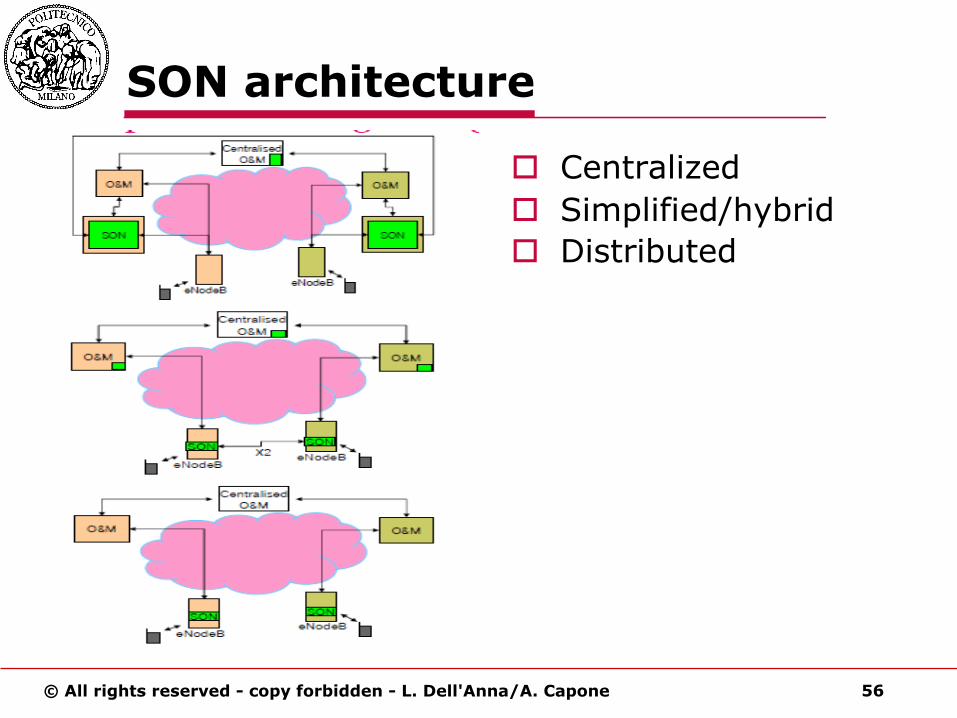
SON architecture
o Centralizedo Simplified/hybrido Distributed
© All rights reserved - copy forbidden - L. Dell'Anna/A. Capone 56
3. LTE radio interface
© All rights reserved - copy forbidden - L. Dell'Anna/A. Capone 57
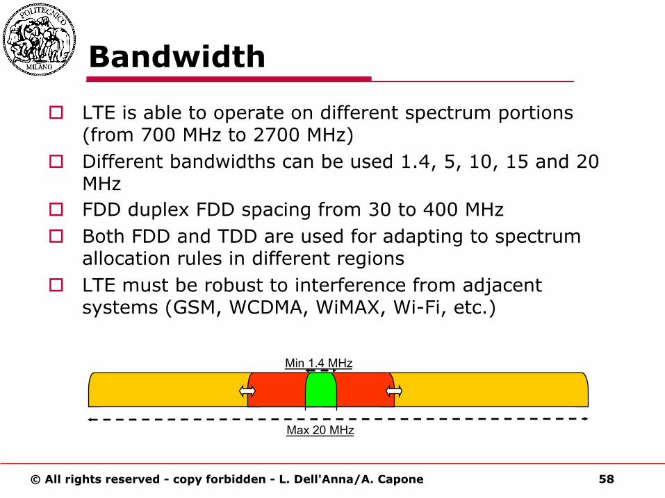
Bandwidth
o LTE is able to operate on different spectrum portions (from 700 MHz to 2700 MHz)
o Different bandwidths can be used 1.4, 5, 10, 15 and 20 MHz
o FDD duplex FDD spacing from 30 to 400 MHzo Both FDD and TDD are used for adapting to spectrum
allocation rules in different regionso LTE must be robust to interference from adjacent
systems (GSM, WCDMA, WiMAX, Wi-Fi, etc.)
Min 1.4 MHz
Max 20 MHz
© All rights reserved - copy forbidden - L. Dell'Anna/A. Capone 58
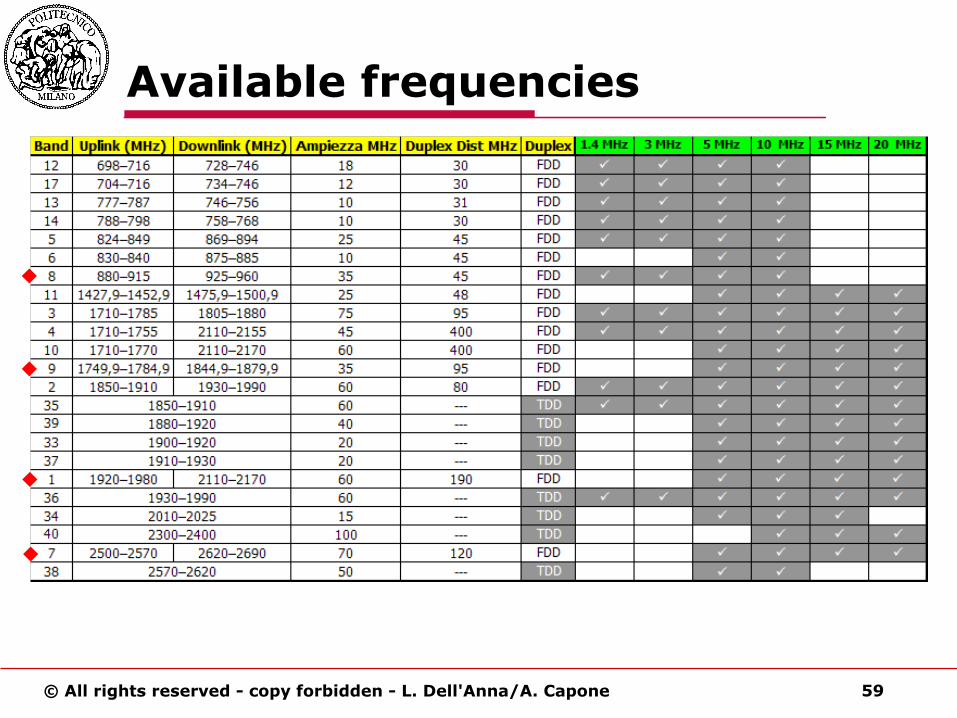
Available frequencies
© All rights reserved - copy forbidden - L. Dell'Anna/A. Capone 59
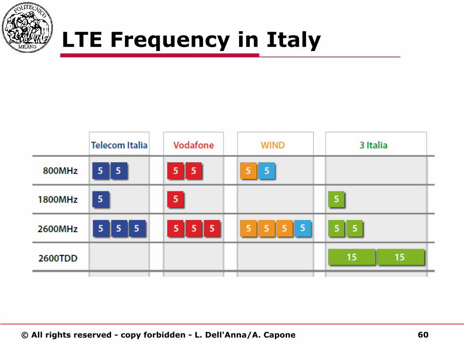
LTE Frequency in Italy
© All rights reserved - copy forbidden - L. Dell'Anna/A. Capone 60
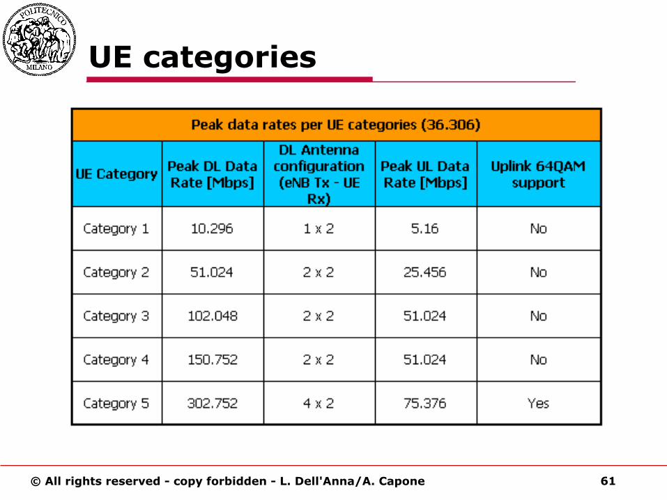
UE categories
© All rights reserved - copy forbidden - L. Dell'Anna/A. Capone 61
Enabling technologies
o Multi carrier modulation (OFDM/OFDMA)
o Multiple antennas (MIMO)
o Adaptive modulation and coding
o Soft recombination of transmitted packets and retransmitted packets (HARQ)
o Packet switching at the radio interface
© All rights reserved - copy forbidden - L. Dell'Anna/A. Capone 62
OFDMA
o LTE usesn OFDMA in Downlinkn SC-FDMA in Uplink
o OFDMA (Orthogonal Frequency Division Multiple Access)
o SC-FDMA (Single Carrier Frequency Division Multiple Access)
© All rights reserved - copy forbidden - L. Dell'Anna/A. Capone 63
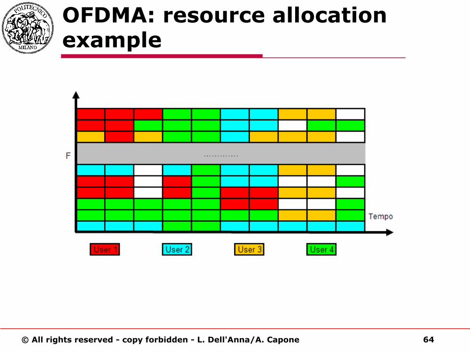
OFDMA: resource allocation example
© All rights reserved - copy forbidden - L. Dell'Anna/A. Capone 64
Channel adaptation
o Link Adaptation (Rate Control)
o Scheduling
o Hybrid ARQ
© All rights reserved - copy forbidden - L. Dell'Anna/A. Capone 65
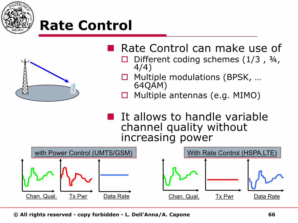
Chan. Qual. Tx Pwr Data Rate Chan. Qual. Tx Pwr Data Rate
with Power Control (UMTS/GSM) With Rate Control (HSPA,LTE)
Rate Controln Rate Control can make use of
o Different coding schemes (1/3 , ¾, 4/4)
o Multiple modulations (BPSK, … 64QAM)
o Multiple antennas (e.g. MIMO)
n It allows to handle variable channel quality without increasing power
© All rights reserved - copy forbidden - L. Dell'Anna/A. Capone 66
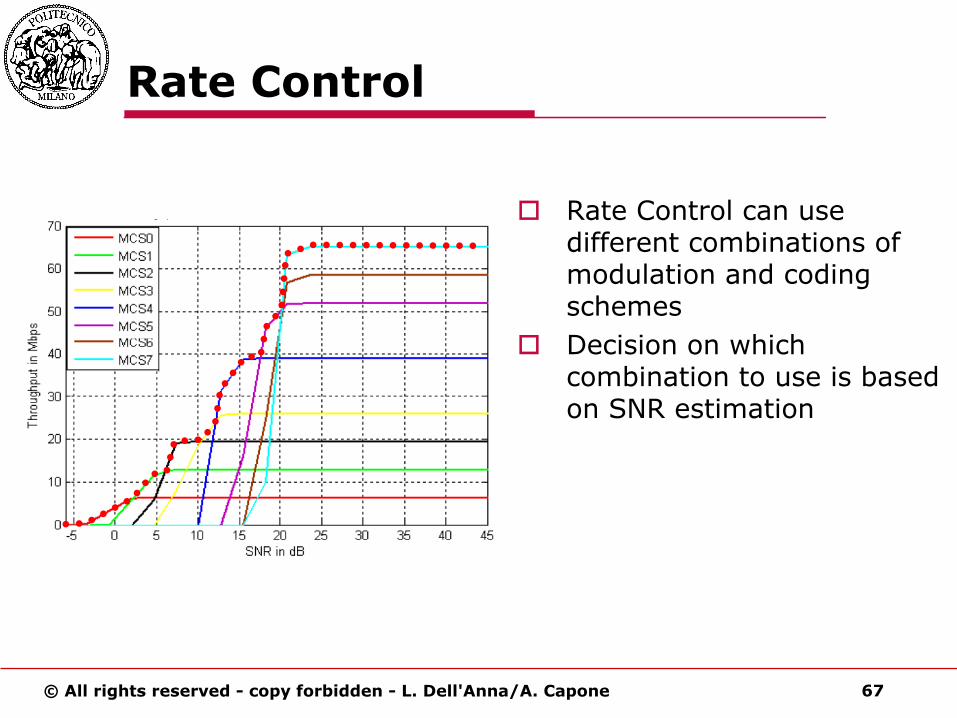
Rate Control
o Rate Control can use different combinations of modulation and coding schemes
o Decision on which combination to use is based on SNR estimation
© All rights reserved - copy forbidden - L. Dell'Anna/A. Capone 67
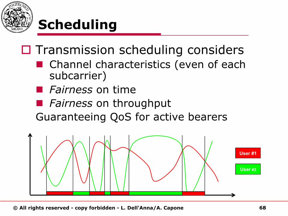
Scheduling
o Transmission scheduling considersn Channel characteristics (even of each
subcarrier)n Fairness on timen Fairness on throughputGuaranteeing QoS for active bearers
User #1
User #2
© All rights reserved - copy forbidden - L. Dell'Anna/A. Capone 68
Hybrid ARQ
o Forward Error Correction
o Soft Combining
© All rights reserved - copy forbidden - L. Dell'Anna/A. Capone 69
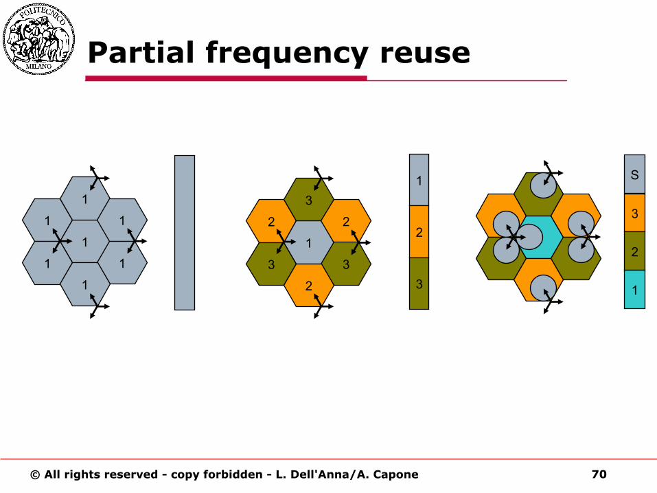
Partial frequency reuse
21
3
3
2
32
11
1
1
1
11
S
3
2
1
1
2
3
© All rights reserved - copy forbidden - L. Dell'Anna/A. Capone 70
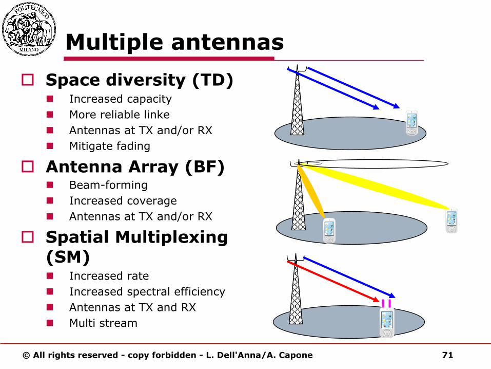
Multiple antennaso Space diversity (TD)
n Increased capacityn More reliable linken Antennas at TX and/or RXn Mitigate fading
o Antenna Array (BF)n Beam-formingn Increased coveragen Antennas at TX and/or RX
o Spatial Multiplexing (SM)n Increased raten Increased spectral efficiencyn Antennas at TX and RXn Multi stream
© All rights reserved - copy forbidden - L. Dell'Anna/A. Capone 71
3.1 LTE Downlink OFDMA
© All rights reserved - copy forbidden - L. Dell'Anna/A. Capone 72
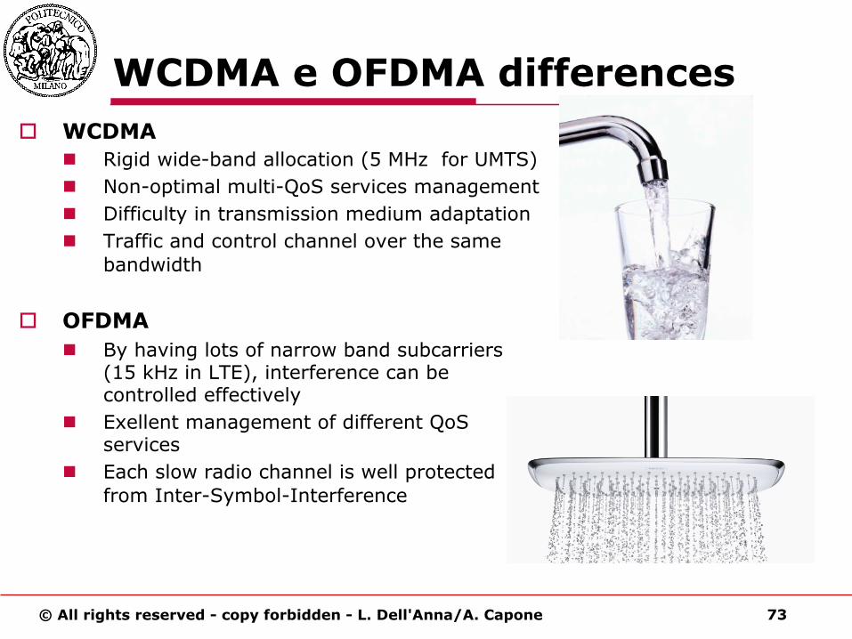
WCDMA e OFDMA differenceso WCDMA
n Rigid wide-band allocation (5 MHz for UMTS)n Non-optimal multi-QoS services managementn Difficulty in transmission medium adaptationn Traffic and control channel over the same
bandwidth
o OFDMAn By having lots of narrow band subcarriers
(15 kHz in LTE), interference can be controlled effectively
n Exellent management of different QoS services
n Each slow radio channel is well protected from Inter-Symbol-Interference
© All rights reserved - copy forbidden - L. Dell'Anna/A. Capone 73
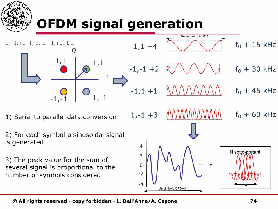
OFDM signal generation
1) Serial to parallel data conversion
2) For each symbol a sinusoidal signal is generated
3) The peak value for the sum of several signal is proportional to the number of symbols considered
Un simbolo OFDMA
Q
I
-1,1 1,1
1,-1-1,-1-1,1 +135°
1,1 +45°
1,-1 +315°
-1,-1 +225°
f0 + 15 kHz
f0 + 30 kHz
f0 + 45 kHz
f0 + 60 kHz
4
0
-4
2
-2
t
…,+1,+1,-1,-1,-1,+1,+1,-1,…
Un simbolo OFDMA
N sotto-portanti
B
© All rights reserved - copy forbidden - L. Dell'Anna/A. Capone 74
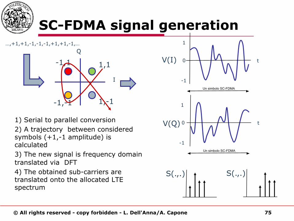
SC-FDMA signal generation
1) Serial to parallel conversion2) A trajectory between considered symbols (+1,-1 amplitude) is calculated3) The new signal is frequency domain translated via DFT4) The obtained sub-carriers are translated onto the allocated LTE spectrum
Q
I
-1,1 1,1
1,-1-1,-1
…,+1,+1,-1,-1,-1,+1,+1,-1,…
0
-1
1
t
Un simbolo SC-FDMA
0 t
Un simbolo SC-FDMA
V(I)
V(Q)
S(.,.) S(.,.)
-1
1
© All rights reserved - copy forbidden - L. Dell'Anna/A. Capone 75
Packet Switched Radio Interface
o All protocols are packet switchedo Transmission interval of 1 ms (in HSDPA
it is 2 ms) comparable to coherence time of the channel
o MAC layer implementsn Adaptive schedulingn Multiple Antenna technology (MIMO)n Rate control
© All rights reserved - copy forbidden - L. Dell'Anna/A. Capone 76
TDD and FDD frames
o Two duplexing schemes are specified: FDD e TDD
o In FDD, assigned spectrum is in pairs (e.g. 20+20 MHz), one for the downlink and one for the uplink
o In TDD the same spectrum (e.g. 10 MHz) is assigned to downlink and uplink but in different times
o Frame formats for FDD and TDD are called type 1 and type 2 respectively
© All rights reserved - copy forbidden - L. Dell'Anna/A. Capone 77
TDD Frame
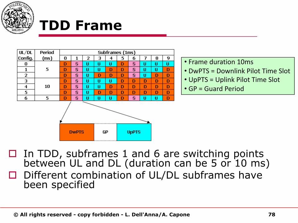
o In TDD, subframes 1 and 6 are switching points between UL and DL (duration can be 5 or 10 ms)
o Different combination of UL/DL subframes have been specified
• Frameduration10ms• DwPTS=DownlinkPilotTimeSlot• UpPTS=UplinkPilotTimeSlot• GP=GuardPeriod
© All rights reserved - copy forbidden - L. Dell'Anna/A. Capone 78
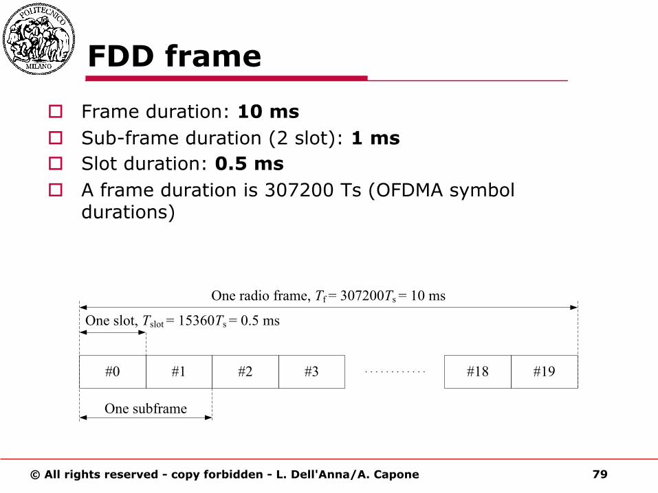
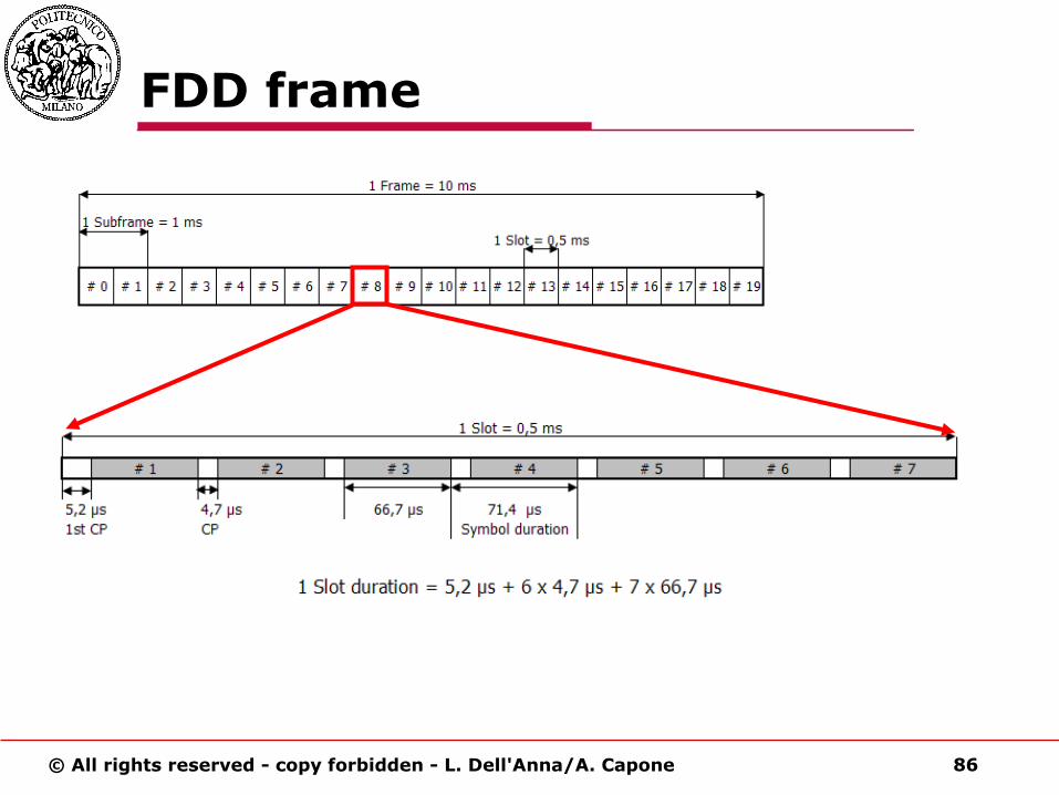
FDD frame
o Frame duration: 10 mso Sub-frame duration (2 slot): 1 mso Slot duration: 0.5 mso A frame duration is 307200 Ts (OFDMA symbol
durations)
#0 #1 #2 #3 #19#18
One radio frame, Tf = 307200Ts = 10 ms
One slot, Tslot = 15360Ts = 0.5 ms
One subframe
© All rights reserved - copy forbidden - L. Dell'Anna/A. Capone 79
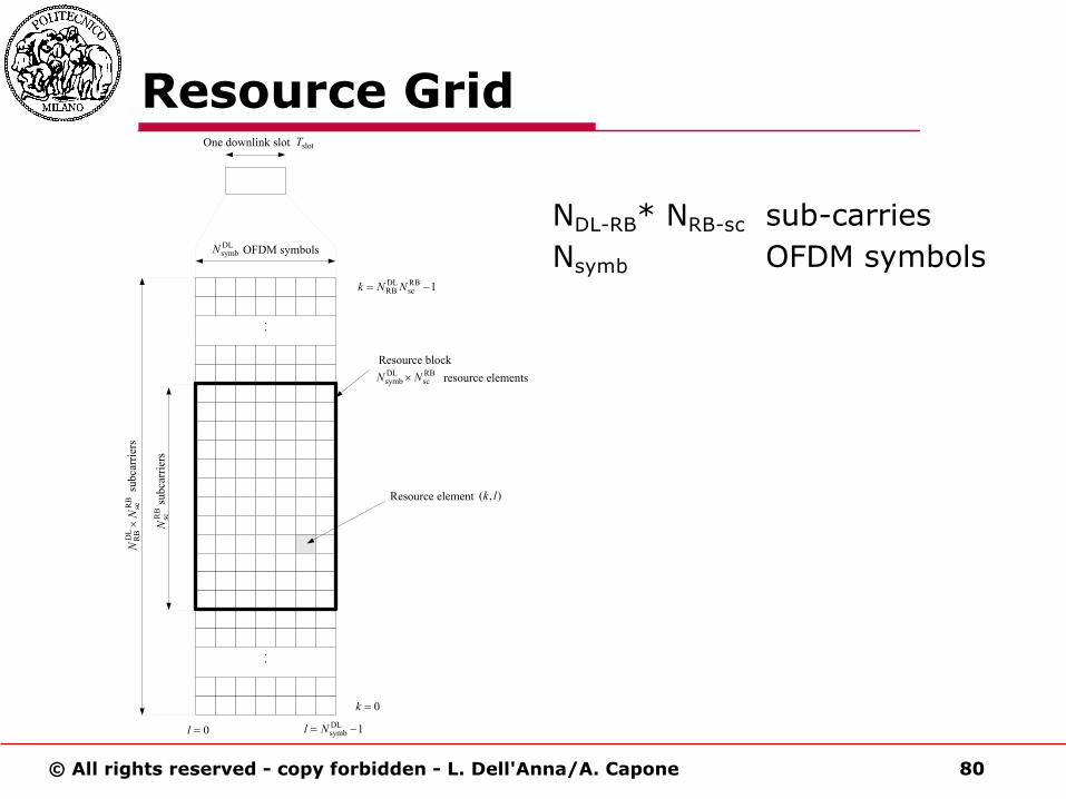
Resource Grid
NDL-RB* NRB-sc sub-carriesNsymb OFDM symbolsDL
symbN OFDM symbols
One downlink slot slotT
0=l 1DLsymb -= Nl
RB
scDL
RBN
N´
subc
arrie
rs
RB
scN
subc
arrie
rs
RBsc
DLsymb NN ´
Resource blockresource elements
Resource element ),( lk
0=k
1RBsc
DLRB -= NNk
© All rights reserved - copy forbidden - L. Dell'Anna/A. Capone 80
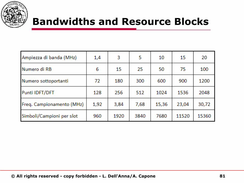
Bandwidths and Resource Blocks
© All rights reserved - copy forbidden - L. Dell'Anna/A. Capone 81
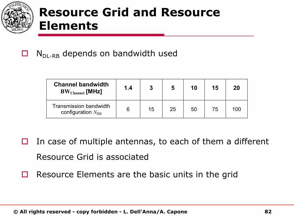
Resource Grid and Resource Elements
o NDL-RB depends on bandwidth used
o In case of multiple antennas, to each of them a different
Resource Grid is associated
o Resource Elements are the basic units in the grid
Channel bandwidth BWChannel [MHz] 1.4 3 5 10 15 20
Transmission bandwidth configuration NRB 6 15 25 50 75 100
© All rights reserved - copy forbidden - L. Dell'Anna/A. Capone 82
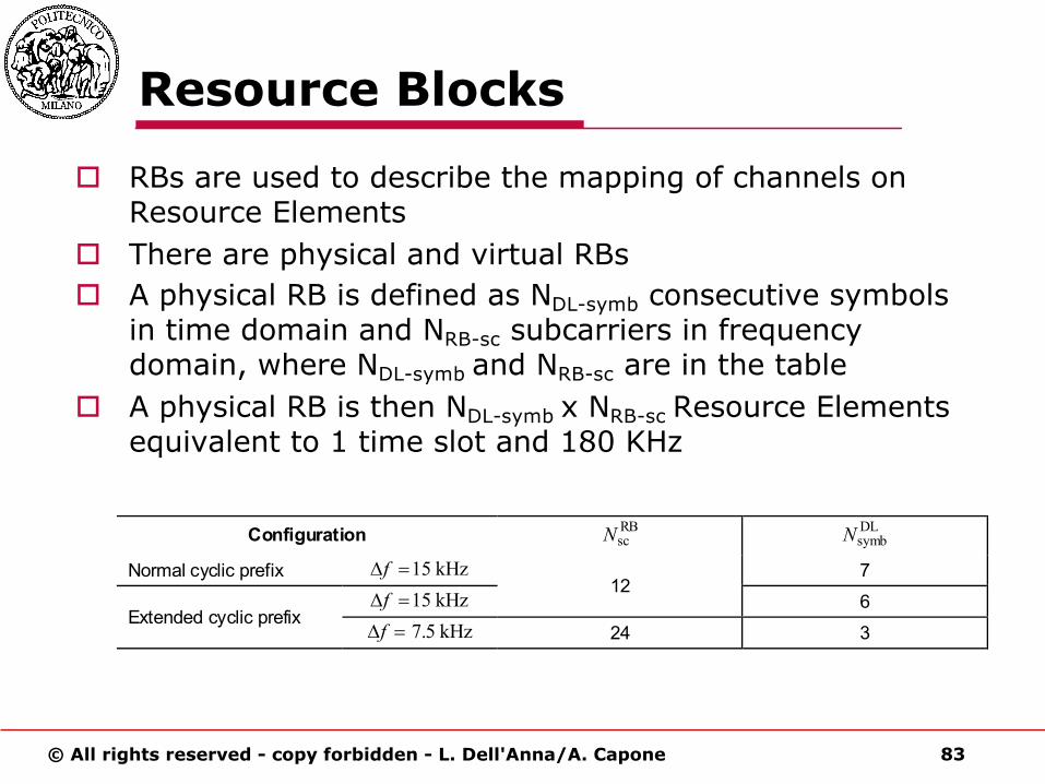
Resource Blocks
o RBs are used to describe the mapping of channels on Resource Elements
o There are physical and virtual RBso A physical RB is defined as NDL-symb consecutive symbols
in time domain and NRB-sc subcarriers in frequency domain, where NDL-symb and NRB-sc are in the table
o A physical RB is then NDL-symb x NRB-sc Resource Elements equivalent to 1 time slot and 180 KHz
Configuration RBscN DL
symbN Normal cyclic prefix kHz 15=Df 7
kHz 15=Df 12
6 Extended cyclic prefix
kHz 5.7=Df 24 3
© All rights reserved - copy forbidden - L. Dell'Anna/A. Capone 83
Resource Blocks
o Physical RBs are numbered from 0 to NDL-RB-1
o Virtual RB have the same size of physical ones and are divided inton Virtual RB Localized Typen Virtual RB Distributed Type
o Resource Elements can be grouped into RE Groups, which are used for mapping channels on REs
© All rights reserved - copy forbidden - L. Dell'Anna/A. Capone 84
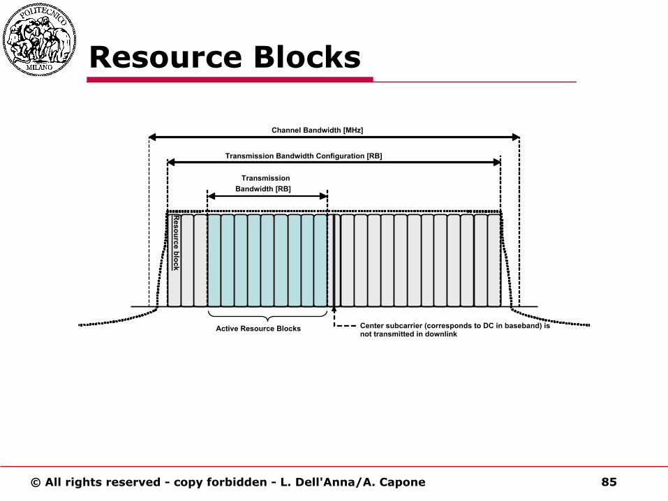
Resource Blocks
TransmissionBandwidth [RB]
Transmission Bandwidth Configuration [RB]
Channel Bandwidth [MHz]
Center subcarrier (corresponds to DC in baseband) is not transmitted in downlink
Active Resource Blocks
Resource block
© All rights reserved - copy forbidden - L. Dell'Anna/A. Capone 85
FDD frame
© All rights reserved - copy forbidden - L. Dell'Anna/A. Capone 86
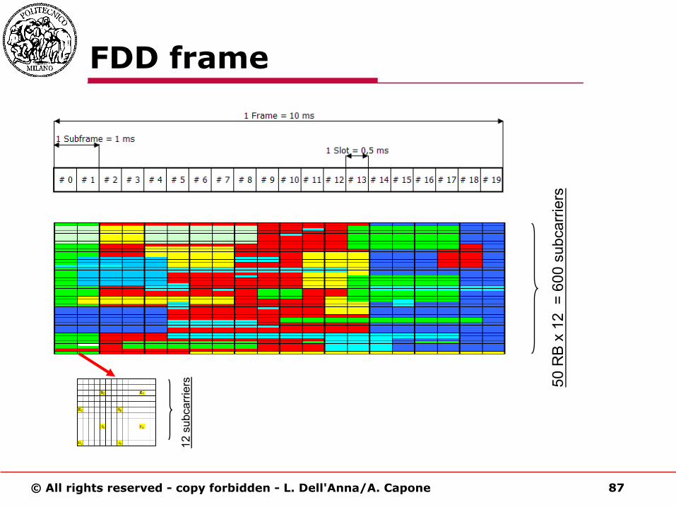
FDD frame
50 R
B x
12 =
600
sub
carri
ers
12 s
ubca
rrier
s
© All rights reserved - copy forbidden - L. Dell'Anna/A. Capone 87
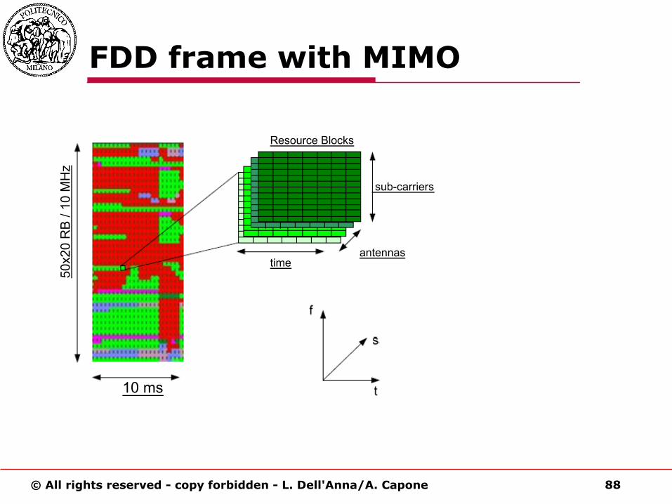
FDD frame with MIMO
sub-carriers
antennastime
10 ms
50x2
0 R
B / 1
0 M
Hz
Resource Blocks
© All rights reserved - copy forbidden - L. Dell'Anna/A. Capone 88
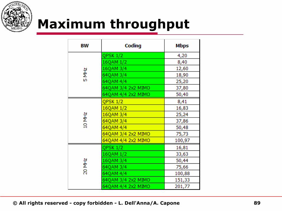
Maximum throughput
© All rights reserved - copy forbidden - L. Dell'Anna/A. Capone 89
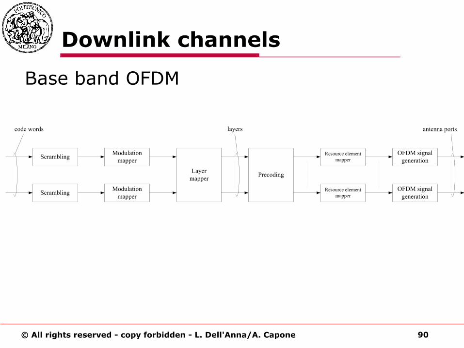
Downlink channels
Base band OFDM
Scrambling Modulation mapper
Layermapper Precoding
Resource element mapper
OFDM signal generation
Resource element mapper
OFDM signal generationScrambling Modulation
mapper
layers antenna portscode words
© All rights reserved - copy forbidden - L. Dell'Anna/A. Capone 90
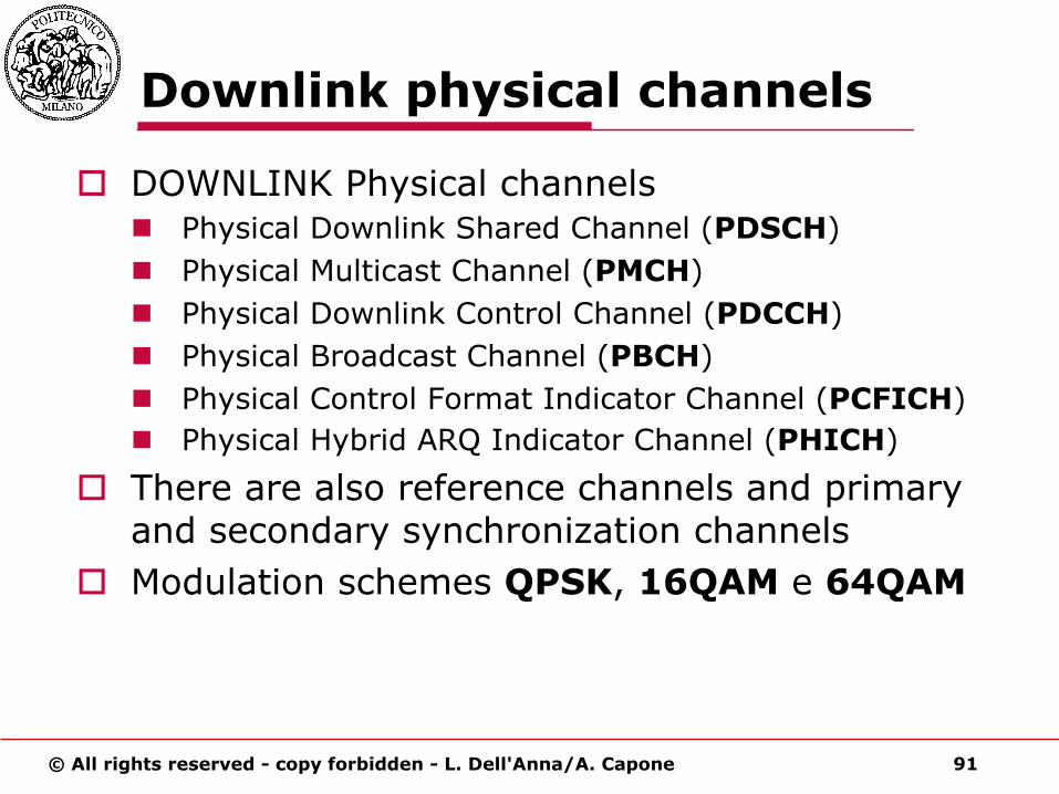
Downlink physical channels
o DOWNLINK Physical channelsn Physical Downlink Shared Channel (PDSCH)n Physical Multicast Channel (PMCH)n Physical Downlink Control Channel (PDCCH)n Physical Broadcast Channel (PBCH)n Physical Control Format Indicator Channel (PCFICH) n Physical Hybrid ARQ Indicator Channel (PHICH)
o There are also reference channels and primary and secondary synchronization channels
o Modulation schemes QPSK, 16QAM e 64QAM
© All rights reserved - copy forbidden - L. Dell'Anna/A. Capone 91
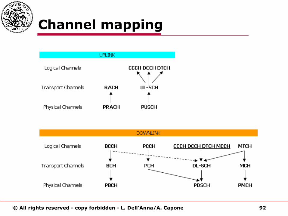
Channel mapping
© All rights reserved - copy forbidden - L. Dell'Anna/A. Capone 92
3.2 LTE Uplink SC-FDMA
© All rights reserved - copy forbidden - L. Dell'Anna/A. Capone 93
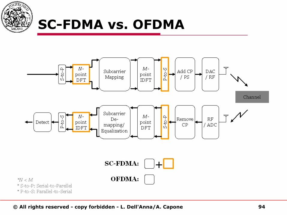
SC-FDMA vs. OFDMA
© All rights reserved - copy forbidden - L. Dell'Anna/A. Capone 94
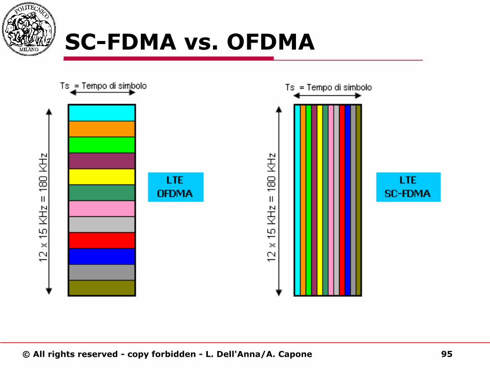
SC-FDMA vs. OFDMA
© All rights reserved - copy forbidden - L. Dell'Anna/A. Capone 95
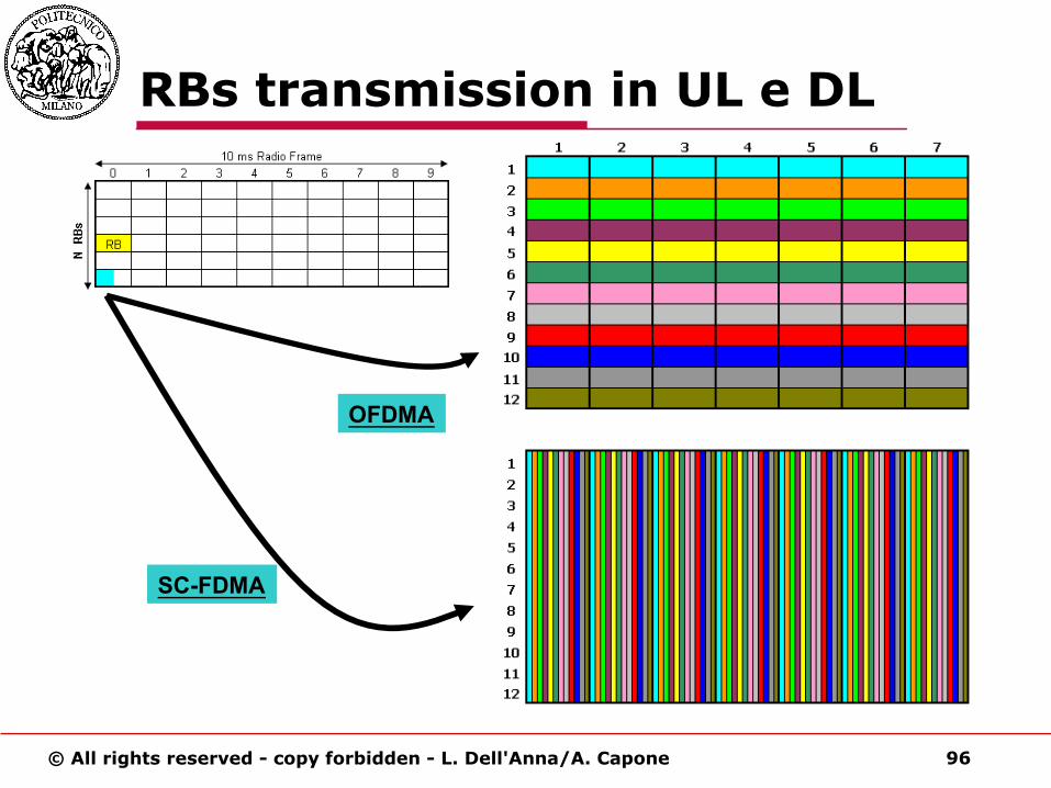
RBs transmission in UL e DL
SC-FDMA
OFDMA
© All rights reserved - copy forbidden - L. Dell'Anna/A. Capone 96
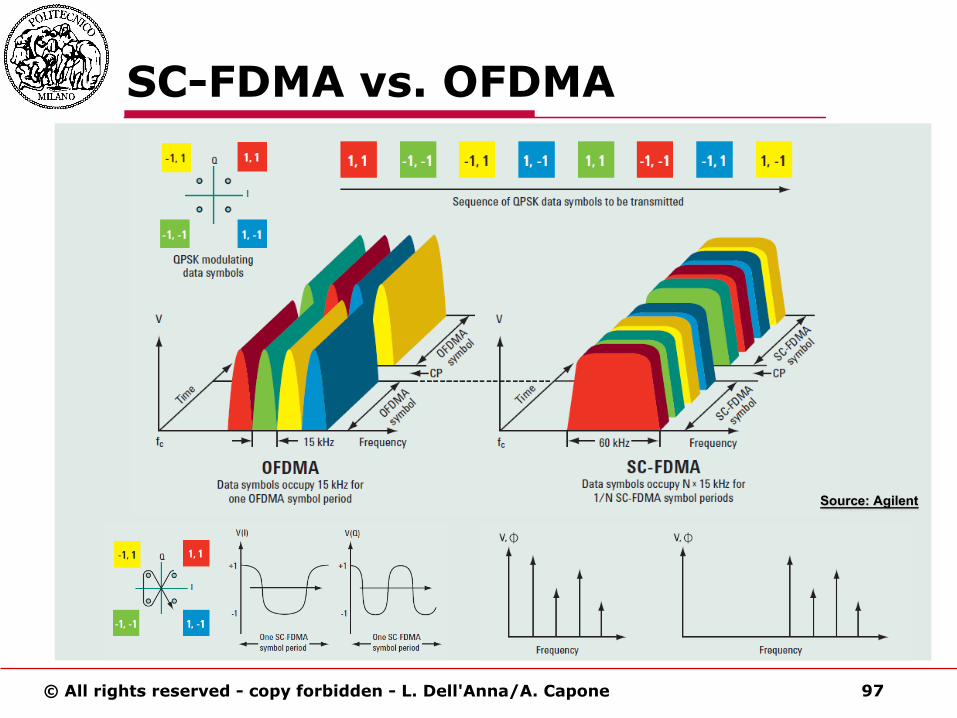
SC-FDMA vs. OFDMA
Source: Agilent
© All rights reserved - copy forbidden - L. Dell'Anna/A. Capone 97
UL frame
o Similar to that of the DLo Same number of symbols and RBso Same frame durationo The SC-FDMA modulation scheme
does not introduces differences
© All rights reserved - copy forbidden - L. Dell'Anna/A. Capone 98
Uplink physical channels
o UPLINK physical channelsn Physical Random Access Channel (PRACH)
o Access requestso Time Advance
n Physical Uplink Shared Channel (PUSCH)o Uplink data channel
n Physical Uplink Control Channel (PUCCH) o Uplink signaling channel
o Modulation schemes: QPSK, 16QAM e 64QAM
© All rights reserved - copy forbidden - L. Dell'Anna/A. Capone 99
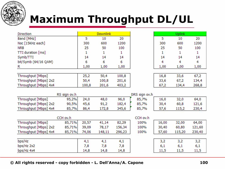
Maximum Throughput DL/UL
© All rights reserved - copy forbidden - L. Dell'Anna/A. Capone 100