Embed Size (px)
Citation preview
MRI Design Guide April 2008
Guide Plates 4-1
Section 4: Guide Plates Page
Patient Areas
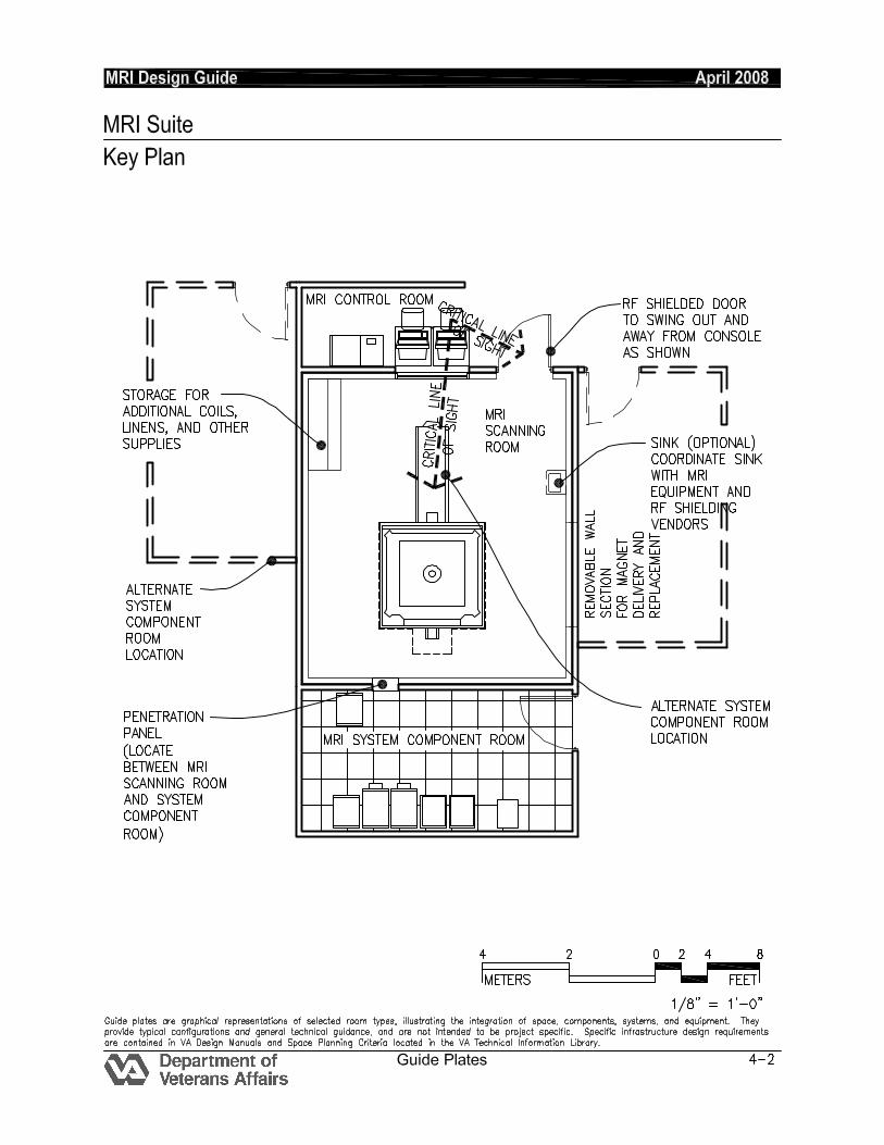
MRI Scanning/Control/System Component Rooms Key Plan ..................................... 4-2
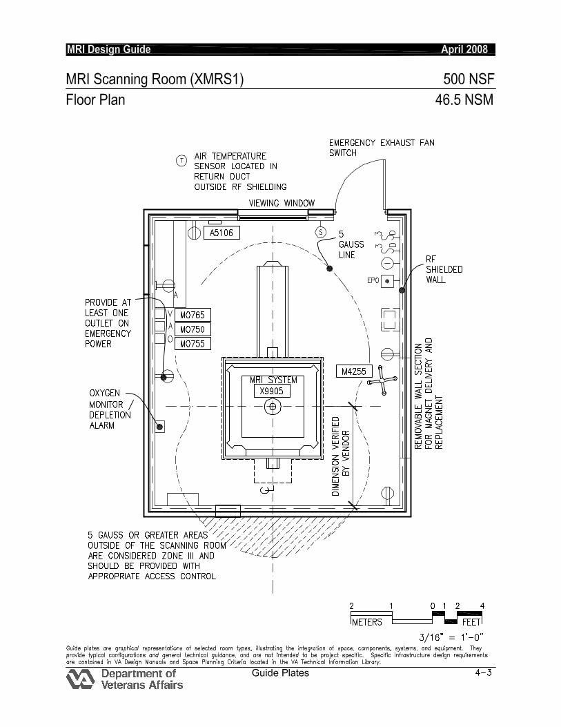
MRI Scanning Room................... 4-3
MRI Control Room .................... 4-11
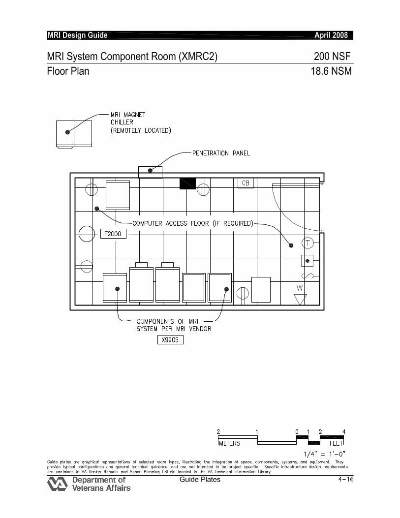
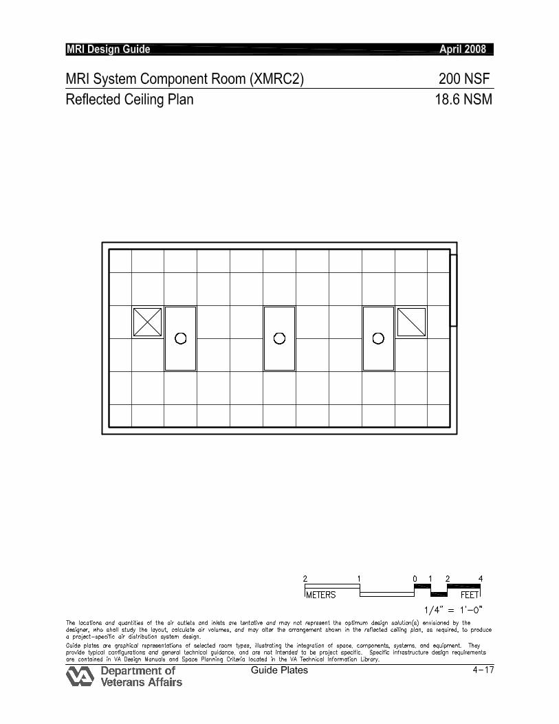
MRI System Component Room ........................................ 4-16
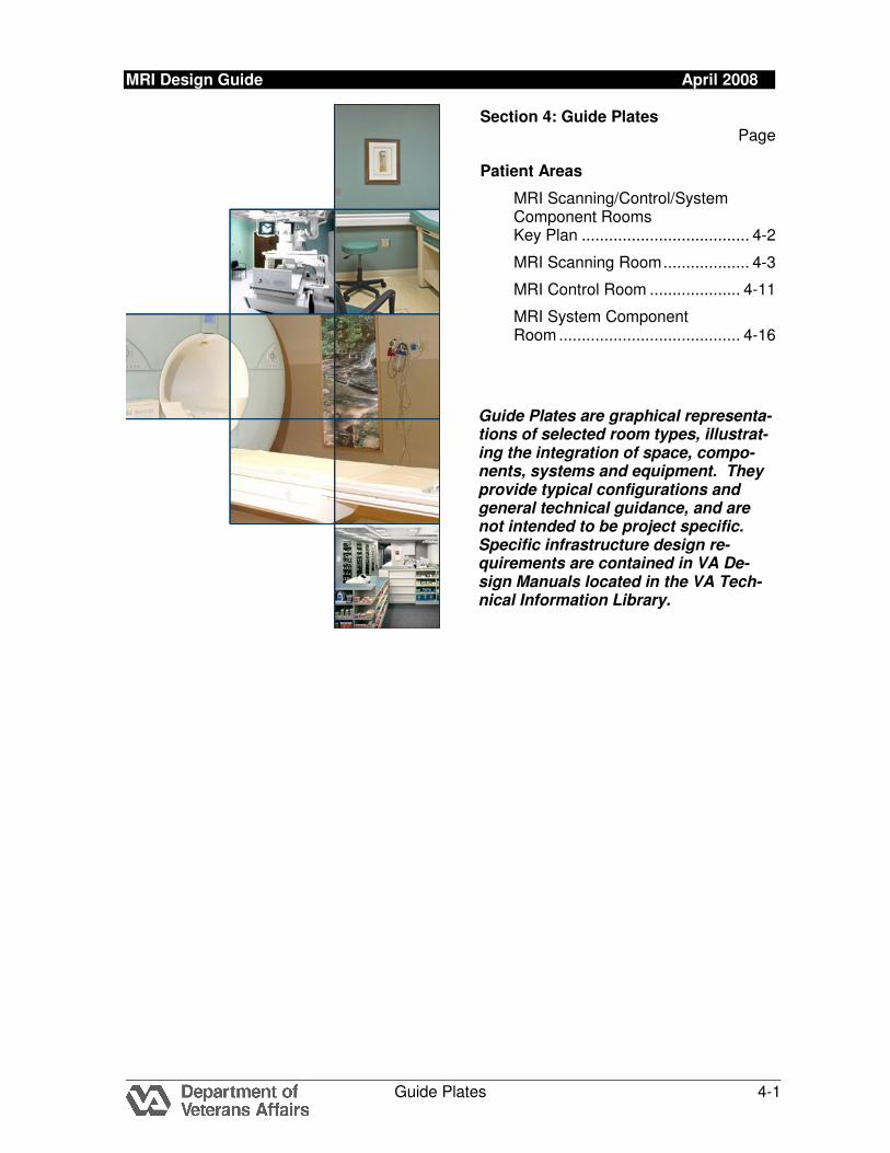
Guide Plates are graphical representa-tions of selected room types, illustrat-ing the integration of space, compo-nents, systems and equipment. They provide typical configurations and general technical guidance, and are not intended to be project specific. Specific infrastructure design re-quirements are contained in VA De-sign Manuals located in the VA Tech-nical Information Library.
MRI Design Guide April 2008
Guide Plates 4-7
MRI SCANNING ROOM (XMRS1): Design Standards ARCHITECTURAL Ceiling: Acoustical Ceiling Tile RF Ceiling Height: Coordinate w/ equipment
manufacturer Wall Finish: Paint Wainscot: -- Base: Resilient Base / Cove Floor Finish: Static Dissipating Flooring Slab Depression: MR Manufacturer may
require floor trench / raceway Sound Protection: NC 40
Notes:
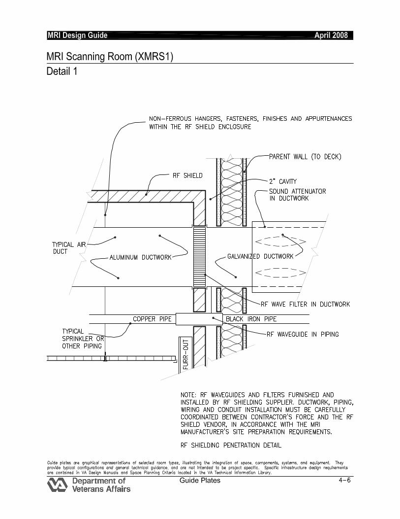
1. 4’0” wide RF door into Scanning Room coordinated radio frequency and magnetic shielding requirements with equipment manufacturer.
2. RF Window from Control Room to Scanning Room
LIGHTING General: 30 fc
Notes:
1. Dual switched recessed, lensed incandescent down light with 100 W, A-21 lamps.
2. LED Down lighting or illuminated graphic display.
POWER General: 3,200 W (Receptacles) Emergency: --
Notes:
1. 480 V, 3 phase, flush-mounted circuit breaker with shunt trip for MRI system. Coordinate rating with system supplier.
2. 480 V, 3 phase, flush-mounted circuit breaker with shunt-trip for computer room A/C unit (when provided). Coordinate rating with system supplier.
3. 3DC power supply (Rectifier) for MRI Scanning Room lighting (when provided). Rating as required for room lighting load.
COMMUNICATION/SPECIAL SYSTEMS ADP: -- Data: -- Telephone: -- Intercom:MRI Scanning Room and Control Room. Via MRI Equipment Nurse Call: -- Public Address: -- Radio/Entertainment: As Required MATV: -- CCTV:MRI Scanning Room and Control Room. As Required MID: -- Security/Duress: -- VTEL: -- VA Satellite TV: -- -- HEATING, VENTILATING AND AIR CONDITIONING Inside Design Conditions: 70°F - 75°F (21°C - 24°) 40% - 60% RH Coordinate with MRI Manufacturer Minimum Air Changes per hour: 12 -Supply Air 100% Exhaust: No 100% Outside air: No Room Air Balance: Positive Dedicated Exhaust System: Yes – Note 2 Occupancy: 4 people AC Load-Equipment: 10,000 Btuh
(3,000W) AC Load Lighting: 2.0 W/SF (21 W/M
2)
Notes:
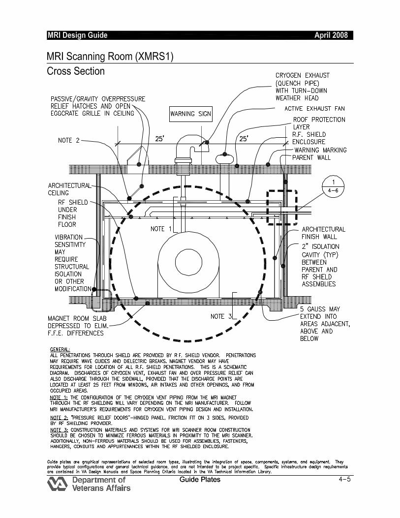
1. Provide nonferrous material for piping, ductwork, and hangers inside the shielding enclosure, as well as in all associated dampers. All serviceable equipment should be located outside the Scanning Room.
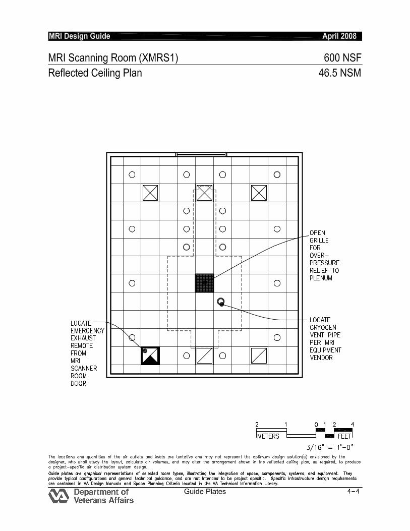
2. Provide an automatic / manual emergency exhaust system (minimum 12 AC/HR).The emergency exhaust fan is activated either automatically by the MRI alarm panel or manually by wall mounted switch, one in the MRI Scanning Room and one in the MRI Control Room. Shutoff the return air whenever the emergency exhaust fan is
MRI Design Guide April 2008
Guide Plates 4-8
activated. This emergency exhaust fan should be on emergency power.
3. Provide a separate cryogen exhaust (quench pipe) from magnet to outside for cryogen boil-off and quench. Protect discharge point from wind-driven rain. Install in accordance with MRI manufacturer’s requirements.
4. Depending upon the particular MRI manufacturer, a dedicated fan, in addition to the emergency exhaust fan, may be required to remove air at the ventilation interface on the magnet.
5. Provide wave guides for all ductwork and all piping penetrating the RF shield enclosure. RF wave guides furnished and installed by RF shielding vendor.
6. An MRI magnet chiller is provided by the MRI manufacturer. Install this chiller in accordance with MRI manufacturer’s requirements.
7. The oxygen sensor / depletion alarm will not remain reliable if calibration and preventative maintenance is not performed per manufacturer’s requirements. Oxygen sensor is not to be used for emergency exhaust fan activation except for MRI systems that do not provide a quench alarm relay for exhaust fan tie-in.
8. Refer to HVAC design manual for additional information.
9. Verify cooling loads and other specific requirements with the equipment manufacturer on the specific project.
PLUMBING AND MEDICAL GASES Cold Water: As Required. Hot Water: As Required Laboratory Air: -- Laboratory Vacuum: -- Sanitary Drain: As Required Reagent grade Water: -- Medical Air: One wall outlet Medical Vacuum: One wall outlet Oxygen: One wall outlet
Notes:
1. Provide nonferrous material for piping, and hangers inside the shielding enclosure.
2. Coordinate dielectric couplings, wave guides, and piping routing / grounding requirements with MRI and RF shield vendors.
MRI Design Guide April 2008
Guide Plates 4-9
MRI SCANNING ROOM (XMRS1): Equipment Guide List
JSN NAME QTY ACQ / INS DESCRIPTION SPEC
A1010 Telecommunication Outlet 1 CC Telecommunication outlet location.
27 31 00
A5106 Waste Disposal Unit, Sharps w/Glove Dispenser
1 W The unit is designed for the disposal of sharps and complies with OSHA guidelines for the handling of sharps. It shall house a 5 quart container and be capable of being mounted on a wall. It shall have a glove dispenser attached. The unit shall be secured by a locked enclosure.
F0355 Footstool, Straight (MR CONDITIONAL)
1 W Step stool. Used to assist patients getting on and off exam or surgical tables. Fitted with electrically conductive rubber tips.
M0750 Flowmeter, Air, Connect w/50 PSI Supply (MR CONDITIONAL)
1 W Air flowmeter. Unit has a stainless steel needle valve with clear flowtube for connection to 50 PSI air outlet from central pipeline system. Requires the appropriate adapter for connection to the wall outlet and fitting to connect to tubing. Database prices reflect fittings with an attached DISS power outlet. Other outlet and adapter configurations are available.
M0755 Flowmeter, Oxygen, Low Flow (MR CONDITIONAL)
1 W Oxygen flowmeter. Consists of a clear crystal flowtube calibrated to 3.5 or 8 LPM depending on manufacturer. For oxygen regulation in hospital settings. Database pricing includes DISS fitting and DISS power outlet and wall adapter. Other fitting and adapter configurations are available.
M0765 Regulator, Vacuum (MR CONDITIONAL)
1 W An air/oxygen mixer is designed to accurately control a pressurized gas mixing with an oxygen concentration. Unit contains audible alarms to warn of supply failure, an auxiliary outlet and a oxygen concentration control adjustment range from 21% to 100%. The unit can also be used to supply an accurate pre-mixed gas source to respiration or ventilator units. A specific application may require an additional air inlet filter/water trap.
MRI Design Guide April 2008
Guide Plates 4-10
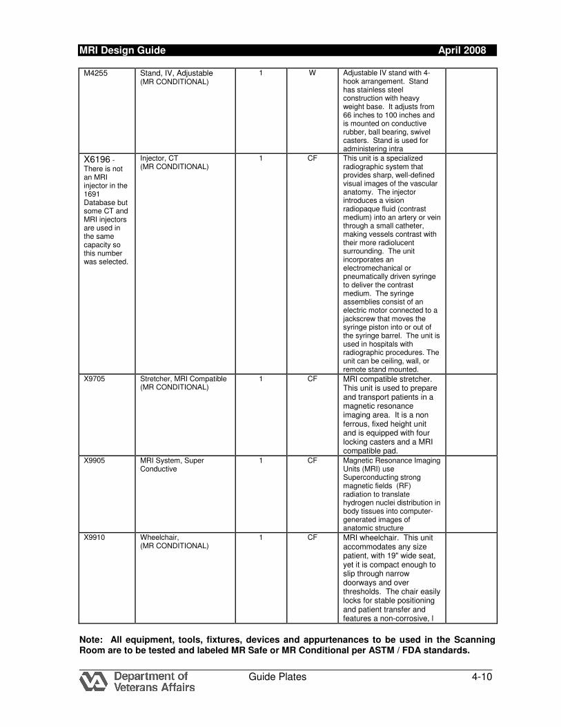
M4255 Stand, IV, Adjustable (MR CONDITIONAL)
1 W Adjustable IV stand with 4-hook arrangement. Stand has stainless steel construction with heavy weight base. It adjusts from 66 inches to 100 inches and is mounted on conductive rubber, ball bearing, swivel casters. Stand is used for administering intra
X6196 - There is not an MRI injector in the 1691 Database but some CT and MRI injectors are used in the same capacity so this number was selected.
Injector, CT (MR CONDITIONAL)
1 CF This unit is a specialized radiographic system that provides sharp, well-defined visual images of the vascular anatomy. The injector introduces a vision radiopaque fluid (contrast medium) into an artery or vein through a small catheter, making vessels contrast with their more radiolucent surrounding. The unit incorporates an electromechanical or pneumatically driven syringe to deliver the contrast medium. The syringe assemblies consist of an electric motor connected to a jackscrew that moves the syringe piston into or out of the syringe barrel. The unit is used in hospitals with radiographic procedures. The unit can be ceiling, wall, or remote stand mounted.
X9705 Stretcher, MRI Compatible (MR CONDITIONAL)
1 CF MRI compatible stretcher. This unit is used to prepare and transport patients in a magnetic resonance imaging area. It is a non ferrous, fixed height unit and is equipped with four locking casters and a MRI compatible pad.
X9905 MRI System, Super Conductive
1 CF Magnetic Resonance Imaging Units (MRI) use Superconducting strong magnetic fields (RF) radiation to translate hydrogen nuclei distribution in body tissues into computer-generated images of anatomic structure
X9910 Wheelchair, (MR CONDITIONAL)
1 CF MRI wheelchair. This unit accommodates any size patient, with 19" wide seat, yet it is compact enough to slip through narrow doorways and over thresholds. The chair easily locks for stable positioning and patient transfer and features a non-corrosive, l
Note: All equipment, tools, fixtures, devices and appurtenances to be used in the Scanning Room are to be tested and labeled MR Safe or MR Conditional per ASTM / FDA standards.
MRI Design Guide April 2008
Guide Plates 4-13
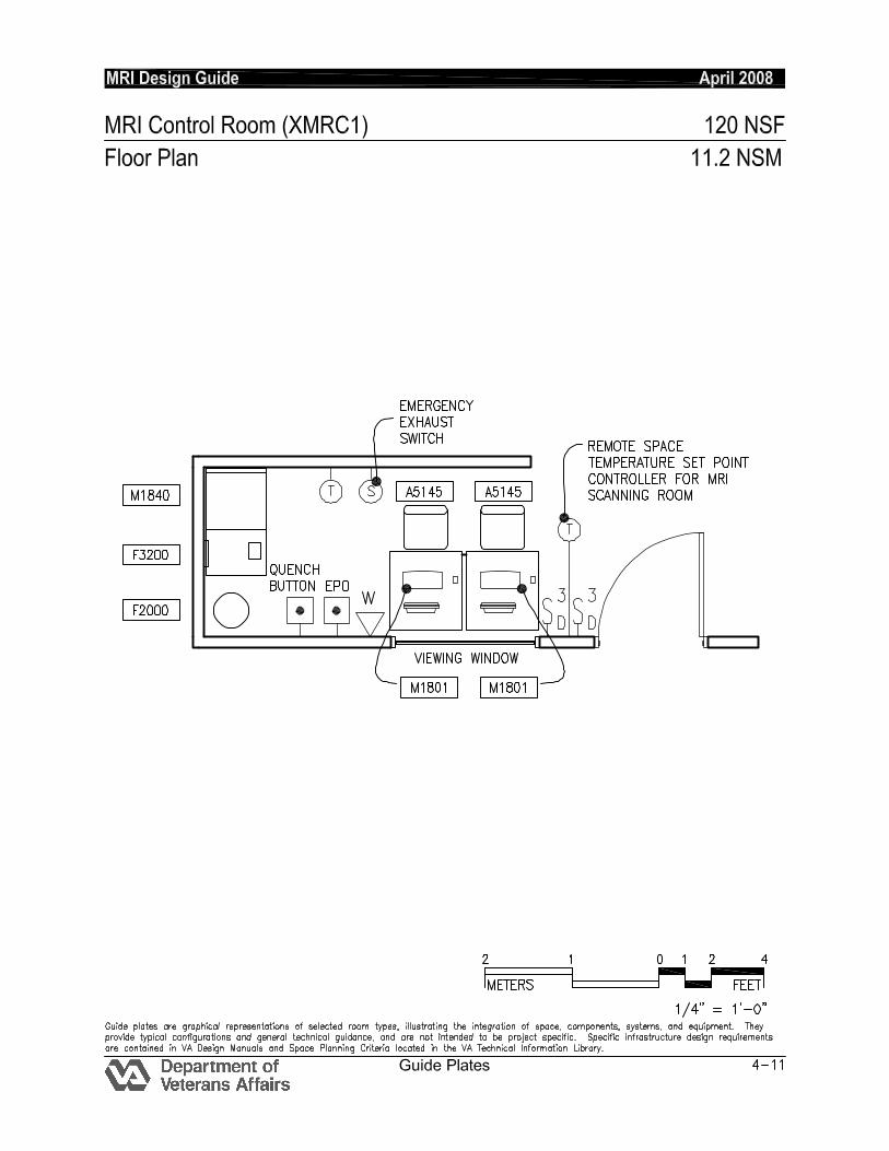
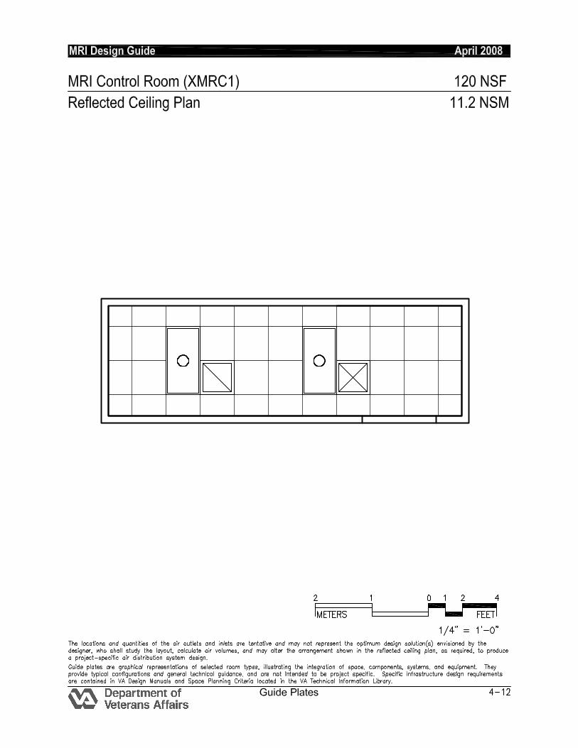
MRI CONTROL ROOM (XMRC1): Design Standards ARCHITECTURAL Ceiling: Acoustical Ceiling Tile Ceiling Height: Coordinate w/ equipment
manufacturer Wall Finish: Paint Wainscot: -- Base: Resilient Base Floor Finish: Vinyl Composition tile Slab Depression: -- Sound Protection: NC 40
Notes:
1. 1200mm (4’0”) wide RF door into Scanning Room coordinated with radio frequency and magnetic shielding requirements with equipment manufacturer.
LIGHTING General: 30 fc
Notes:
1. 2’x4’ recessed dimmable fluorescent light fixture, glare control, acrylic prismatic lens, w/2 – F32T8 lamps, 4,100 K, CRI-85 (minimum.
POWER General: 3,200 W (Receptacles) Emergency: 1,200 W
Notes:
1. EPO: 480 V, 3 phase, flush-mounted circuit breaker with shunt trip for MRI system. Coordinate rating with system supplier.
2. 480 V, 3 phase, flush-mounted circuit breaker with shunt-trip for computer room A/C unit (when provided). Coordinate rating with system supplier.
3. 208 V, 3 phase flush-mounted circuit breaker for power conditioner or UPS equipment (when provided) for MRI computer equipment.
COMMUNICATION / SPECIAL SYSTEMS ADP / LAN Telecommunications outlets
Two per room minimum Data: -- Telephone: Yes Intercom: MRI Scanning Room and Control Room Via MRI Equipment Nurse Call: -- PACS: two4-port telecommunications outlets per PACS station Public Address: -- Radio/Entertainment: -- MATV: -- CCTV: As Required MID: -- Security/Duress: -- VTEL: -- VA Satellite TV: -- HEATING, VENTILATING AND AIR CONDITIONING Inside Design Conditions: 70°F - 75°F (21°C - 24°) 30% to 60% RH Minimum Air Changes per hour: 6
- Supply Air 100% Exhaust: No 100% Outside air No Room Air Balance: Positive Dedicated Exhaust System: No Occupancy: 2 people AC Load-Equipment: 5,000 Btuh
(1,500W) AC Load-Lighting: 1.0 W/SF (17 W/M
2)
Notes: 1. Verify cooling loads and other specific
requirements with the equipment manufacturer on a specific project.
PLUMBING AND MEDICAL GASES Cold Water: -- Hot Water: -- Laboratory Air: -- Laboratory Vacuum: -- Sanitary Drain: -- Reagent grade Water: -- Medical Air: -- Medical Vacuum: -- Oxygen: --
MRI Design Guide April 2008
Guide Plates 4-14
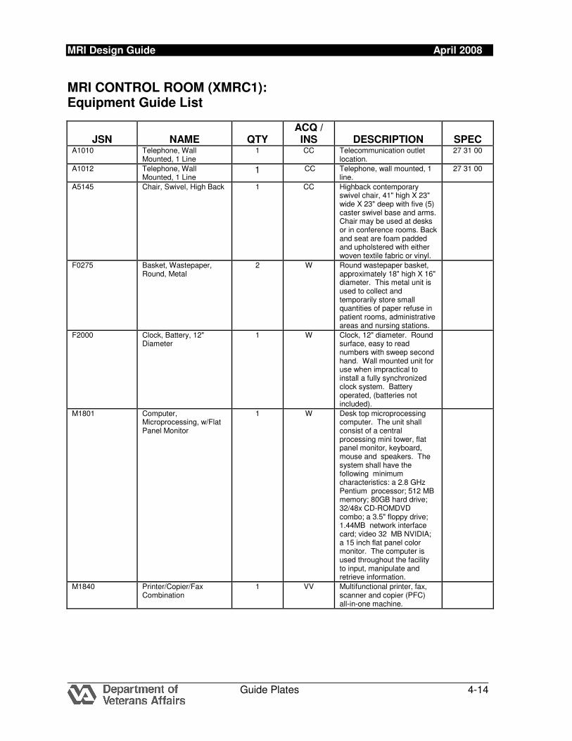
MRI CONTROL ROOM (XMRC1): Equipment Guide List
JSN NAME QTY ACQ / INS DESCRIPTION SPEC
A1010 Telephone, Wall Mounted, 1 Line
1 CC Telecommunication outlet location.
27 31 00
A1012 Telephone, Wall Mounted, 1 Line
1 CC Telephone, wall mounted, 1 line.
27 31 00
A5145 Chair, Swivel, High Back 1 CC Highback contemporary swivel chair, 41" high X 23" wide X 23" deep with five (5) caster swivel base and arms. Chair may be used at desks or in conference rooms. Back and seat are foam padded and upholstered with either woven textile fabric or vinyl.
F0275 Basket, Wastepaper, Round, Metal
2 W Round wastepaper basket, approximately 18" high X 16" diameter. This metal unit is used to collect and temporarily store small quantities of paper refuse in patient rooms, administrative areas and nursing stations.
F2000 Clock, Battery, 12" Diameter
1 W Clock, 12" diameter. Round surface, easy to read numbers with sweep second hand. Wall mounted unit for use when impractical to install a fully synchronized clock system. Battery operated, (batteries not included).
M1801 Computer, Microprocessing, w/Flat Panel Monitor
1 W Desk top microprocessing computer. The unit shall consist of a central processing mini tower, flat panel monitor, keyboard, mouse and speakers. The system shall have the following minimum characteristics: a 2.8 GHz Pentium processor; 512 MB memory; 80GB hard drive; 32/48x CD-ROMDVD combo; a 3.5" floppy drive; 1.44MB network interface card; video 32 MB NVIDIA; a 15 inch flat panel color monitor. The computer is used throughout the facility to input, manipulate and retrieve information.
M1840 Printer/Copier/Fax Combination
1 VV Multifunctional printer, fax, scanner and copier (PFC) all-in-one machine.
MRI Design Guide April 2008
Guide Plates 4-15
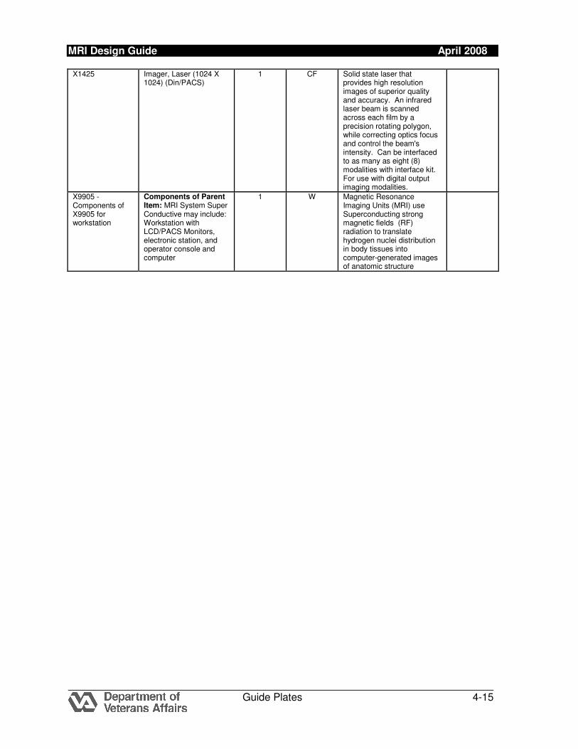
X1425 Imager, Laser (1024 X 1024) (Din/PACS)
1 CF Solid state laser that provides high resolution images of superior quality and accuracy. An infrared laser beam is scanned across each film by a precision rotating polygon, while correcting optics focus and control the beam's intensity. Can be interfaced to as many as eight (8) modalities with interface kit. For use with digital output imaging modalities.
X9905 - Components of X9905 for workstation
Components of Parent Item: MRI System Super Conductive may include: Workstation with LCD/PACS Monitors, electronic station, and operator console and computer
1 W Magnetic Resonance Imaging Units (MRI) use Superconducting strong magnetic fields (RF) radiation to translate hydrogen nuclei distribution in body tissues into computer-generated images of anatomic structure
MRI Design Guide April 2008
Guide Plates 4-18
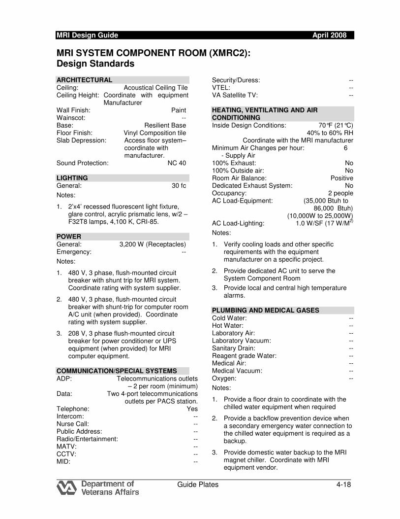
MRI SYSTEM COMPONENT ROOM (XMRC2): Design Standards ARCHITECTURAL Ceiling: Acoustical Ceiling Tile Ceiling Height: Coordinate with equipment
Manufacturer Wall Finish: Paint Wainscot: -- Base: Resilient Base Floor Finish: Vinyl Composition tile Slab Depression: Access floor system–
coordinate with manufacturer.
Sound Protection: NC 40 LIGHTING General: 30 fc
Notes:
1. 2’x4’ recessed fluorescent light fixture, glare control, acrylic prismatic lens, w/2 – F32T8 lamps, 4,100 K, CRI-85.
POWER General: 3,200 W (Receptacles) Emergency: --
Notes:
1. 480 V, 3 phase, flush-mounted circuit breaker with shunt trip for MRI system. Coordinate rating with system supplier.
2. 480 V, 3 phase, flush-mounted circuit breaker with shunt-trip for computer room A/C unit (when provided). Coordinate rating with system supplier.
3. 208 V, 3 phase flush-mounted circuit breaker for power conditioner or UPS equipment (when provided) for MRI computer equipment.
COMMUNICATION/SPECIAL SYSTEMS ADP: Telecommunications outlets – 2 per room (minimum) Data: Two 4-port telecommunications outlets per PACS station. Telephone: Yes Intercom: -- Nurse Call: -- Public Address: -- Radio/Entertainment: -- MATV: -- CCTV: -- MID: --
Security/Duress: -- VTEL: -- VA Satellite TV: -- HEATING, VENTILATING AND AIR CONDITIONING Inside Design Conditions: 70°F (21°C) 40% to 60% RH Coordinate with the MRI manufacturer Minimum Air Changes per hour: 6
- Supply Air 100% Exhaust: No 100% Outside air: No Room Air Balance: Positive Dedicated Exhaust System: No Occupancy: 2 people AC Load-Equipment: (35,000 Btuh to
86,000 Btuh) (10,000W to 25,000W)
AC Load-Lighting: 1.0 W/SF (17 W/M2)
Notes:
1. Verify cooling loads and other specific requirements with the equipment manufacturer on a specific project.
2. Provide dedicated AC unit to serve the System Component Room
3. Provide local and central high temperature alarms.
PLUMBING AND MEDICAL GASES Cold Water: -- Hot Water: -- Laboratory Air: -- Laboratory Vacuum: -- Sanitary Drain: -- Reagent grade Water: -- Medical Air: -- Medical Vacuum: -- Oxygen: --
Notes:
1. Provide a floor drain to coordinate with the chilled water equipment when required
2. Provide a backflow prevention device when a secondary emergency water connection to the chilled water equipment is required as a backup.
3. Provide domestic water backup to the MRI magnet chiller. Coordinate with MRI equipment vendor.
MRI Design Guide April 2008
Guide Plates 4-19
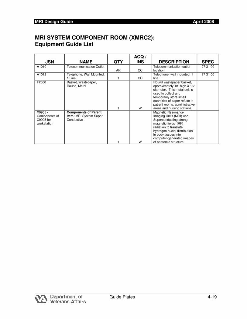
MRI SYSTEM COMPONENT ROOM (XMRC2): Equipment Guide List
JSN NAME QTY ACQ / INS DESCRIPTION SPEC
A1010 Telecommunication Outlet AR CC
Telecommunication outlet location.
27 31 00
A1012 Telephone, Wall Mounted, 1 Line 1 CC
Telephone, wall mounted, 1 line.
27 31 00
F2000 Basket, Wastepaper, Round, Metal
1 W
Round wastepaper basket, approximately 18" high X 16" diameter. This metal unit is used to collect and temporarily store small quantities of paper refuse in patient rooms, administrative areas and nursing stations.
X9905 - Components of X9905 for workstation
Components of Parent Item: MRI System Super Conductive
1 W
Magnetic Resonance Imaging Units (MRI) use Superconducting strong magnetic fields (RF) radiation to translate hydrogen nuclei distribution in body tissues into computer-generated images of anatomic structure

![MRI for Detection of Hepatocellular Carcinoma: Comparison ...mriquestions.com/uploads/3/4/5/7/34572113/youk_mn...sions, especially hepatocellular carcinoma [1–3]. However, evaluation](https://img.pdfslide.us/doc/110x75/5f3ced438bc609735d4a5d4b/mri-for-detection-of-hepatocellular-carcinoma-comparison-sions-especially.jpg)