Embed Size (px)
Citation preview
©W
este
rmo
Tele
indu
stri
AB
MRD-315, MRD-355 & MRD-455
Industrial Mobile Broadband Router GSM / GPRS / EDGE / 3G /
HSDPA / HSUPA / HSPA / 4G LTE
www.westermo.com
User Guide6623-2250
2 6623-2250
Legal informationThe contents of this document are provided “as is”. Except as required by applicable law, no warranties of any kind, either express or implied, including, but not limited to, the implied warranties of merchantability and fitness for a particular purpose, are made in relation to the accuracy and reliability or contents of this document. Westermo reserves the right to revise this document or withdraw it at any time without prior notice.Under no circumstances shall Westermo be responsible for any loss of data or income or any special, incidental, and consequential or indirect damages howsoever caused.More information about Westermo can be found at the following Internet address:http://www.westermo.com
36623-2250
Safety
Before using this unit:
Read this manual completely and gather all information on the unit. Make sure that you understand it fully. Check that your application does not exceed the safe operating specifications for this unit.
Hazardous voltages may occur within this unit when connected to a power supply.
Prevent access to hazardous voltages by disconnecting the unit from its power supply.
Prevent damage to internal electronics from electrostatic discharges (ESD) by discharging your body to a grounding point (e.g. use of wrist strap).
Before installation:
This unit should only be installed by qualified personnel.
This unit should be built-in to an apparatus cabinet, or similar, where access is restricted to service personnel only.
The power supply wiring must be sufficiently fused, and if necessary it must be possible to disconnect manually from the power supply. Ensure compliance to national installation regulations.
This unit uses convection cooling. To avoid obstructing the airflow around the unit, follow the spacing recommendations (see Installation section).
Care recommendationsFollow the care recommendations below to maintain full operation of unit and to fulfil the warranty obligations.
This unit must not be operated with covers or lids removed.Do not attempt to disassemble the unit. There are no user serviceable parts inside.Do not drop, knock or shake the unit, rough handling beyond the specification may cause damage to internal circuit boards.Do not use harsh chemicals, cleaning solvents or strong detergents to clean the unit.Do not paint the unit. Paint can clog the unit and prevent proper operation.Do not expose the unit to any kind of liquids (rain, beverages, etc). The unit is not waterproof. Keep the unit within the specified humidity levels.Do not use or store the unit in dusty, dirty areas, connectors as well as other mechanical part may be damaged.If the unit is not working properly, contact the place of purchase, nearest Westermo distributor office or Westermo Tech support.
GSM specific safetyPlease read and follow the guidelines listed below. The precautions must be observed during all phases of the operation. Breaking these rules may be dangerous, illegal or affect performance of the unit and/or invalidate the unit’s approval and/or warranty.
!
!
4 6623-2250
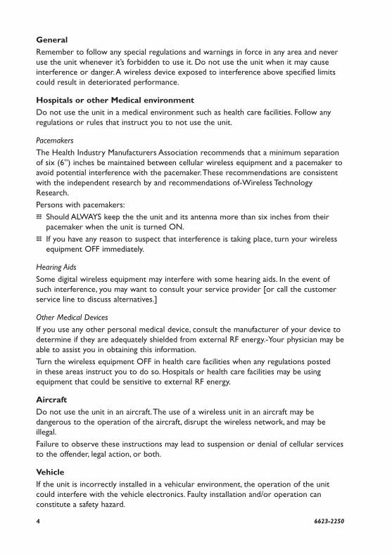
General
Remember to follow any special regulations and warnings in force in any area and never use the unit whenever it’s forbidden to use it. Do not use the unit when it may cause interference or danger. A wireless device exposed to interference above specified limits could result in deteriorated performance.
Hospitals or other Medical environment
Do not use the unit in a medical environment such as health care facilities. Follow any regulations or rules that instruct you to not use the unit.
Pacemakers
The Health Industry Manufacturers Association recommends that a minimum separation of six (6”) inches be maintained between cellular wireless equipment and a pacemaker to avoid potential interference with the pacemaker. These recommendations are consistent with the independent research by and recommendations of-Wireless Technology Research.
Persons with pacemakers:
… Should ALWAYS keep the the unit and its antenna more than six inches from their pacemaker when the unit is turned ON.
… If you have any reason to suspect that interference is taking place, turn your wireless equipment OFF immediately.
Hearing Aids
Some digital wireless equipment may interfere with some hearing aids. In the event of such interference, you may want to consult your service provider [or call the customer service line to discuss alternatives.]
Other Medical Devices
If you use any other personal medical device, consult the manufacturer of your device to determine if they are adequately shielded from external RF energy.-Your physician may be able to assist you in obtaining this information.
Turn the wireless equipment OFF in health care facilities when any regulations posted in these areas instruct you to do so. Hospitals or health care facilities may be using equipment that could be sensitive to external RF energy.
Aircraft
Do not use the unit in an aircraft. The use of a wireless unit in an aircraft may be dangerous to the operation of the aircraft, disrupt the wireless network, and may be illegal.
Failure to observe these instructions may lead to suspension or denial of cellular services to the offender, legal action, or both.
Vehicle
If the unit is incorrectly installed in a vehicular environment, the operation of the unit could interfere with the vehicle electronics. Faulty installation and/or operation can constitute a safety hazard.
56623-2250
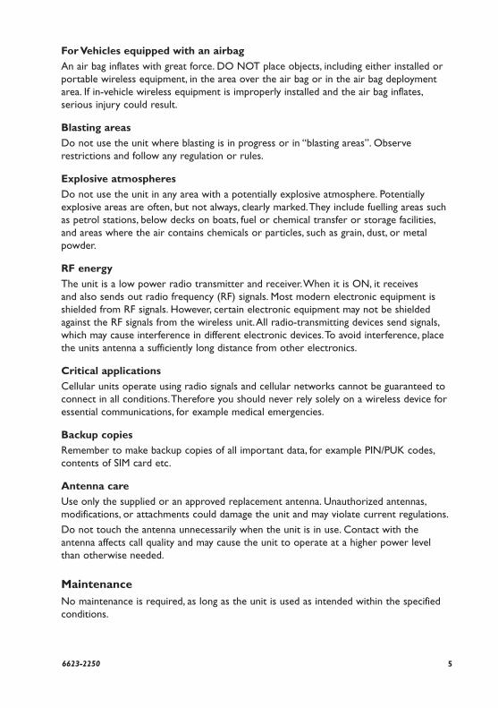
For Vehicles equipped with an airbag
An air bag inflates with great force. DO NOT place objects, including either installed or portable wireless equipment, in the area over the air bag or in the air bag deployment area. If in-vehicle wireless equipment is improperly installed and the air bag inflates, serious injury could result.
Blasting areas
Do not use the unit where blasting is in progress or in “blasting areas”. Observe restrictions and follow any regulation or rules.
Explosive atmospheres
Do not use the unit in any area with a potentially explosive atmosphere. Potentially explosive areas are often, but not always, clearly marked. They include fuelling areas such as petrol stations, below decks on boats, fuel or chemical transfer or storage facilities, and areas where the air contains chemicals or particles, such as grain, dust, or metal powder.
RF energy
The unit is a low power radio transmitter and receiver. When it is ON, it receives and also sends out radio frequency (RF) signals. Most modern electronic equipment is shielded from RF signals. However, certain electronic equipment may not be shielded against the RF signals from the wireless unit. All radio-transmitting devices send signals, which may cause interference in different electronic devices. To avoid interference, place the units antenna a sufficiently long distance from other electronics.
Critical applications
Cellular units operate using radio signals and cellular networks cannot be guaranteed to connect in all conditions. Therefore you should never rely solely on a wireless device for essential communications, for example medical emergencies.
Backup copies
Remember to make backup copies of all important data, for example PIN/PUK codes, contents of SIM card etc.
Antenna care
Use only the supplied or an approved replacement antenna. Unauthorized antennas, modifications, or attachments could damage the unit and may violate current regulations.
Do not touch the antenna unnecessarily when the unit is in use. Contact with the antenna affects call quality and may cause the unit to operate at a higher power level than otherwise needed.
MaintenanceNo maintenance is required, as long as the unit is used as intended within the specified conditions.
6 6623-2250
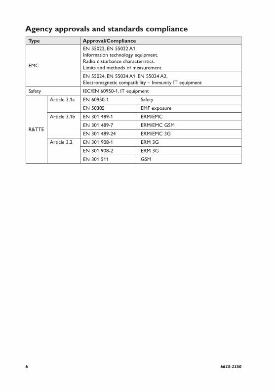
Type Approval/Compliance
EMC
EN 55022, EN 55022 A1, Information technology equipment. Radio disturbance characteristics. Limits and methods of measurement
EN 55024, EN 55024 A1, EN 55024 A2, Electromagnetic compatibility – Immunity IT equipment
Safety IEC/EN 60950-1, IT equipment
R&TTE
Article 3.1a EN 60950-1 Safety
EN 50385 EMF exposure
Article 3.1b EN 301 489-1 ERM/EMC
EN 301 489-7 ERM/EMC GSM
EN 301 489-24 ERM/EMC 3G
Article 3.2 EN 301 908-1 ERM 3G
EN 301 908-2 ERM 3G
EN 301 511 GSM
Agency approvals and standards compliance
76623-2250
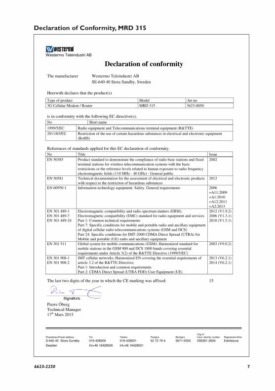
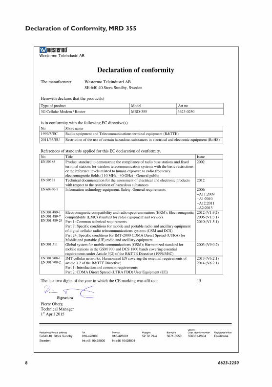
Declaration of Conformity, MRD 315
Westermo Teleindustri AB
Declaration of conformity
Org.nr/ Postadress/Postal address Tel. Telefax Postgiro Bankgiro Corp. identity number Registered office
S-640 40 Stora Sundby 016-428000 016-428001 52 72 79-4 5671-5550 556361-2604 Eskilstuna
Sweden Int+46 16428000 Int+46 16428001
The manufacturer Westermo Teleindustri AB
SE-640 40 Stora Sundby, Sweden
Herewith declares that the product(s)
Type of product Model Art no
3G Cellular Modem / Router MRD 315 3623-0050
is in conformity with the following EC directive(s).
No Short name
1999/5/EC Radio equipment and Telecommunications terminal equipment (R&TTE)
2011/65/EU Restriction of the use of certain hazardous substances in electrical and electronic equipment (RoHS)
References of standards applied for this EC declaration of conformity.
No Title Issue
EN 50385 Product standard to demonstrate the compliance of radio base stations and fixed terminal stations for wireless telecommunication systems with the basic restrictions or the reference levels related to human exposure to radio frequency electromagnetic fields (110 MHz - 40 GHz) - General public
2002
EN 50581 Technical documentation for the assessment of electrical and electronic products with respect to the restriction of hazardous substances
2012
EN 60950-1 Information technology equipment. Safety. General requirements 2006 +A11:2009 +A1:2010 +A12:2011 +A2:2013
EN 301 489-1 EN 301 489-7 EN 301 489-24
Electromagnetic compatibility and radio spectrum matters (ERM); Electromagnetic compatibility (EMC) standard for radio equipment and services Part 1: Common technical requirements Part 7: Specific conditions for mobile and portable radio and ancillary equipment of digital cellular radio telecommunications systems (GSM and DCS) Part 24: Specific conditions for IMT-2000 CDMA Direct Spread (UTRA) for Mobile and portable (UE) radio and ancillary equipment
2012 (V1.9.2) 2006 (V1.3.1) 2010 (V1.5.1)
EN 301 511 Global system for mobile communications (GSM); Harmonized standard for mobile stations in the GSM 900 and DCS 1800 bands covering essential requirements under Article 3(2) of the R&TTE Directive (1999/5/EC)
2003 (V9.0.2)
EN 301 908-1 EN 301 908-2
IMT cellular networks; Harmonized EN covering the essential requirements of article 3.2 of the R&TTE Directive; Part 1: Introduction and common requirements Part 2: CDMA Direct Spread (UTRA FDD) User Equipment (UE)
2013 (V6.2.1) 2014 (V6.2.1)
The last two digits of the year in which the CE marking was affixed: 15
Pierre Öberg Technical Manager 17th Mars 2015
8 6623-2250
Declaration of Conformity, MRD 355
Westermo Teleindustri AB
Declaration of conformity
Org.nr/ Postadress/Postal address Tel. Telefax Postgiro Bankgiro Corp. identity number Registered office
S-640 40 Stora Sundby 016-428000 016-428001 52 72 79-4 5671-5550 556361-2604 Eskilstuna
Sweden Int+46 16428000 Int+46 16428001
The manufacturer Westermo Teleindustri AB
SE-640 40 Stora Sundby, Sweden
Herewith declares that the product(s)
Type of product Model Art no
3G Cellular Modem / Router MRD-355 3623-0250
is in conformity with the following EC directive(s).
No Short name
1999/5/EC Radio equipment and Telecommunications terminal equipment (R&TTE)
2011/65/EU Restriction of the use of certain hazardous substances in electrical and electronic equipment (RoHS)
References of standards applied for this EC declaration of conformity.
No Title Issue EN 50385 Product standard to demonstrate the compliance of radio base stations and fixed
terminal stations for wireless telecommunication systems with the basic restrictions or the reference levels related to human exposure to radio frequency electromagnetic fields (110 MHz - 40 GHz) - General public
2002
EN 50581 Technical documentation for the assessment of electrical and electronic products with respect to the restriction of hazardous substances
2012
EN 60950-1 Information technology equipment. Safety. General requirements 2006 +A11:2009 +A1:2010 +A12:2011 +A2:2013
EN 301 489-1 EN 301 489-7 EN 301 489-24
Electromagnetic compatibility and radio spectrum matters (ERM); Electromagnetic compatibility (EMC) standard for radio equipment and services Part 1: Common technical requirements Part 7: Specific conditions for mobile and portable radio and ancillary equipment of digital cellular radio telecommunications systems (GSM and DCS) Part 24: Specific conditions for IMT-2000 CDMA Direct Spread (UTRA) for Mobile and portable (UE) radio and ancillary equipment
2012 (V1.9.2) 2006 (V1.3.1) 2010 (V1.5.1)
EN 301 511 Global system for mobile communications (GSM); Harmonized standard for mobile stations in the GSM 900 and DCS 1800 bands covering essential requirements under Article 3(2) of the R&TTE Directive (1999/5/EC)
2003 (V9.0.2)
EN 301 908-1 EN 301 908-2
IMT cellular networks; Harmonized EN covering the essential requirements of article 3.2 of the R&TTE Directive; Part 1: Introduction and common requirements Part 2: CDMA Direct Spread (UTRA FDD) User Equipment (UE)
2013 (V6.2.1) 2014 (V6.2.1)
The last two digits of the year in which the CE marking was affixed: 15
Pierre Öberg Technical Manager 1st April 2015
96623-2250
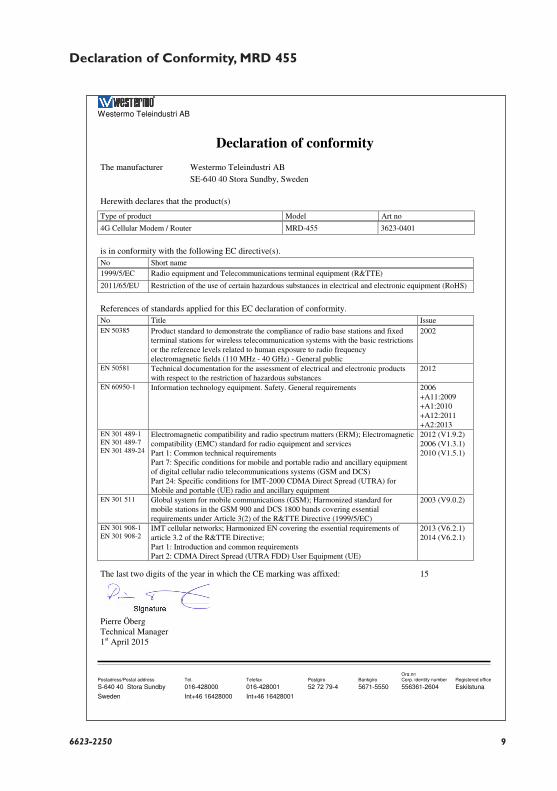
Declaration of Conformity, MRD 455
Westermo Teleindustri AB
Declaration of conformity
Org.nr/ Postadress/Postal address Tel. Telefax Postgiro Bankgiro Corp. identity number Registered office
S-640 40 Stora Sundby 016-428000 016-428001 52 72 79-4 5671-5550 556361-2604 Eskilstuna
Sweden Int+46 16428000 Int+46 16428001
The manufacturer Westermo Teleindustri AB
SE-640 40 Stora Sundby, Sweden
Herewith declares that the product(s)
Type of product Model Art no
4G Cellular Modem / Router MRD-455 3623-0401
is in conformity with the following EC directive(s).
No Short name
1999/5/EC Radio equipment and Telecommunications terminal equipment (R&TTE)
2011/65/EU Restriction of the use of certain hazardous substances in electrical and electronic equipment (RoHS)
References of standards applied for this EC declaration of conformity.
No Title Issue EN 50385 Product standard to demonstrate the compliance of radio base stations and fixed
terminal stations for wireless telecommunication systems with the basic restrictions or the reference levels related to human exposure to radio frequency electromagnetic fields (110 MHz - 40 GHz) - General public
2002
EN 50581 Technical documentation for the assessment of electrical and electronic products with respect to the restriction of hazardous substances
2012
EN 60950-1 Information technology equipment. Safety. General requirements 2006 +A11:2009 +A1:2010 +A12:2011 +A2:2013
EN 301 489-1 EN 301 489-7 EN 301 489-24
Electromagnetic compatibility and radio spectrum matters (ERM); Electromagnetic compatibility (EMC) standard for radio equipment and services Part 1: Common technical requirements Part 7: Specific conditions for mobile and portable radio and ancillary equipment of digital cellular radio telecommunications systems (GSM and DCS) Part 24: Specific conditions for IMT-2000 CDMA Direct Spread (UTRA) for Mobile and portable (UE) radio and ancillary equipment
2012 (V1.9.2) 2006 (V1.3.1) 2010 (V1.5.1)
EN 301 511 Global system for mobile communications (GSM); Harmonized standard for mobile stations in the GSM 900 and DCS 1800 bands covering essential requirements under Article 3(2) of the R&TTE Directive (1999/5/EC)
2003 (V9.0.2)
EN 301 908-1 EN 301 908-2
IMT cellular networks; Harmonized EN covering the essential requirements of article 3.2 of the R&TTE Directive; Part 1: Introduction and common requirements Part 2: CDMA Direct Spread (UTRA FDD) User Equipment (UE)
2013 (V6.2.1) 2014 (V6.2.1)
The last two digits of the year in which the CE marking was affixed: 15
Pierre Öberg Technical Manager 1st April 2015
10 6623-2250
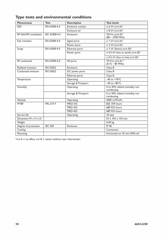
Type tests and environmental conditionsPhenomena Test Description Test levels
ESD EN 61000-4-2 Enclosure contact ± 6 kV (crit A)*
Enclosure air ± 8 kV (crit A)*
RF field AM modulated IEC 61000-4-3 Enclosure 10 V/m (crit A)* (80 – 2700 MHz)
Fast transient EN 61000-4-4 Signal ports ± 1 kV (crit A)*
Power ports ± 2 kV (crit A)*
Surge EN 61000-4-5 Ethernet ports ± 1 kV (direct) (crit B)*
Power ports ± 0.5 kV (line to earth) (crit B)*
± 0.5 kV (line to line) (crit B)*
RF conducted EN 61000-4-6 All ports 10 V/m, (crit A) *(0.15 – 80 MHz)
Radiated emission EN 55022 Enclosure Class B
Conducted emission EN 55022 DC power ports Class B
Ethernet ports Class B
Temperature Operating –40 to +70ºC
Storage & Transport –40 to +85ºC
Humidity Operating 0 to 95% relative humidity non condensing.
Storage & Transport 0 to 95% relative humidity non condensing.
Altitude Operating 2000 m/70 kPa
MTBF MIL-217-F MRD-315 825 759 hours
MRD-355 689 933 hours
MRD-455 689 933 hours
Service life Operating 10 year
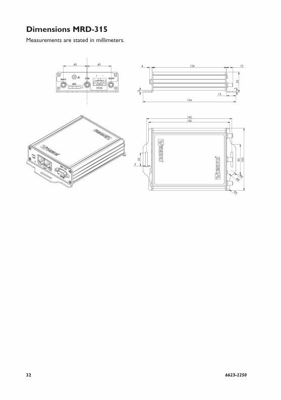
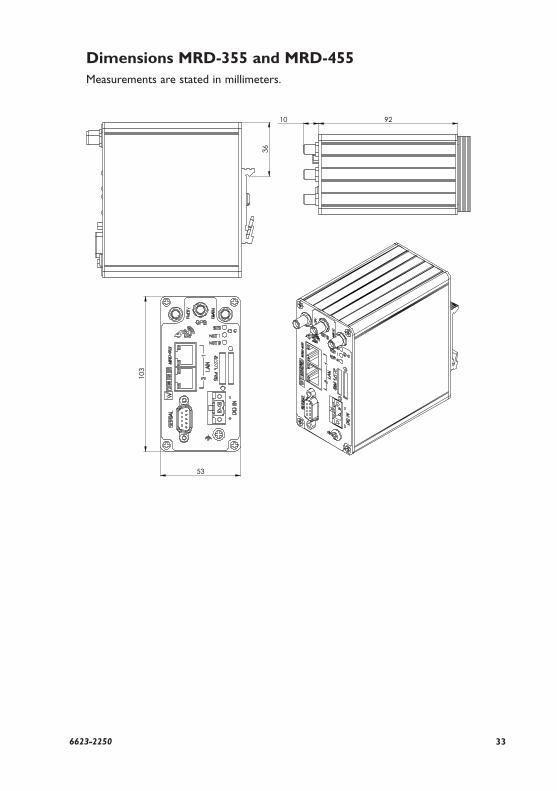
Dimension W x H x D 53 x 103 x 134 mm
Weight 0.40 kg
Degree of protection IEC 529 Enclosure IP 40
Cooling Convection
Mounting Horizontal on 35 mm DIN-rail
*crit A = no effect, crit B = restart without user intervention
116623-2250
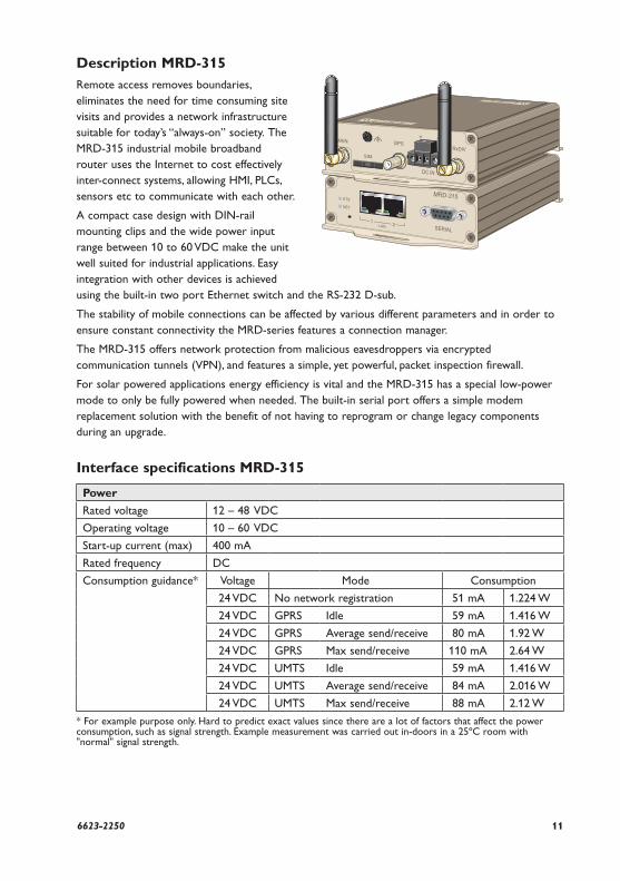
Description MRD-315Remote access removes boundaries, eliminates the need for time consuming site visits and provides a network infrastructure suitable for today’s “always-on” society. The MRD-315 industrial mobile broadband router uses the Internet to cost effectively inter-connect systems, allowing HMI, PLCs, sensors etc to communicate with each other.
A compact case design with DIN-rail mounting clips and the wide power input range between 10 to 60 VDC make the unit well suited for industrial applications. Easy integration with other devices is achieved using the built-in two port Ethernet switch and the RS-232 D-sub.
The stability of mobile connections can be affected by various different parameters and in order to ensure constant connectivity the MRD-series features a connection manager.
The MRD-315 offers network protection from malicious eavesdroppers via encrypted communication tunnels (VPN), and features a simple, yet powerful, packet inspection firewall.
For solar powered applications energy efficiency is vital and the MRD-315 has a special low-power mode to only be fully powered when needed. The built-in serial port offers a simple modem replacement solution with the benefit of not having to reprogram or change legacy components during an upgrade.
Interface specifications MRD-315
Power
Rated voltage 12 – 48 VDC
Operating voltage 10 – 60 VDC
Start-up current (max) 400 mA
Rated frequency DC
Consumption guidance* Voltage Mode Consumption
24 VDC No network registration 51 mA 1.224 W
24 VDC GPRS Idle 59 mA 1.416 W
24 VDC GPRS Average send/receive 80 mA 1.92 W
24 VDC GPRS Max send/receive 110 mA 2.64 W
24 VDC UMTS Idle 59 mA 1.416 W
24 VDC UMTS Average send/receive 84 mA 2.016 W
24 VDC UMTS Max send/receive 88 mA 2.12 W
* For example purpose only. Hard to predict exact values since there are a lot of factors that affect the power consumption, such as signal strength. Example measurement was carried out in-doors in a 25ºC room with "normal" signal strength.
12 6623-2250
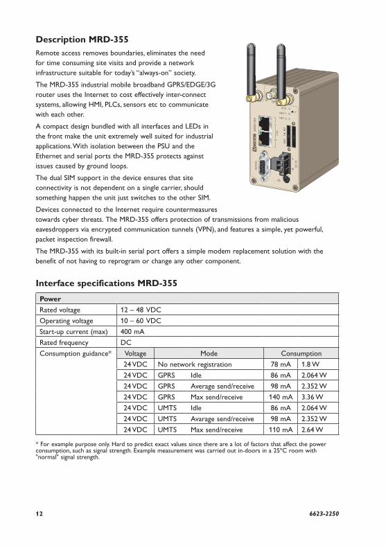
Description MRD-355Remote access removes boundaries, eliminates the need for time consuming site visits and provide a network infrastructure suitable for today’s “always-on” society.
The MRD-355 industrial mobile broadband GPRS/EDGE/3G router uses the Internet to cost effectively inter-connect systems, allowing HMI, PLCs, sensors etc to communicate with each other.
A compact design bundled with all interfaces and LEDs in the front make the unit extremely well suited for industrial applications. With isolation between the PSU and the Ethernet and serial ports the MRD-355 protects against issues caused by ground loops.
The dual SIM support in the device ensures that site connectivity is not dependent on a single carrier, should something happen the unit just switches to the other SIM.
Devices connected to the Internet require countermeasures towards cyber threats. The MRD-355 offers protection of transmissions from malicious eavesdroppers via encrypted communication tunnels (VPN), and features a simple, yet powerful, packet inspection firewall.
The MRD-355 with its built-in serial port offers a simple modem replacement solution with the benefit of not having to reprogram or change any other component.
Interface specifications MRD-355
Power
Rated voltage 12 – 48 VDC
Operating voltage 10 – 60 VDC
Start-up current (max) 400 mA
Rated frequency DC
Consumption guidance* Voltage Mode Consumption
24 VDC No network registration 78 mA 1.8 W
24 VDC GPRS Idle 86 mA 2.064 W
24 VDC GPRS Average send/receive 98 mA 2.352 W
24 VDC GPRS Max send/receive 140 mA 3.36 W
24 VDC UMTS Idle 86 mA 2.064 W
24 VDC UMTS Avarage send/receive 98 mA 2.352 W
24 VDC UMTS Max send/receive 110 mA 2.64 W
* For example purpose only. Hard to predict exact values since there are a lot of factors that affect the power consumption, such as signal strength. Example measurement was carried out in-doors in a 25ºC room with "normal" signal strength.
136623-2250
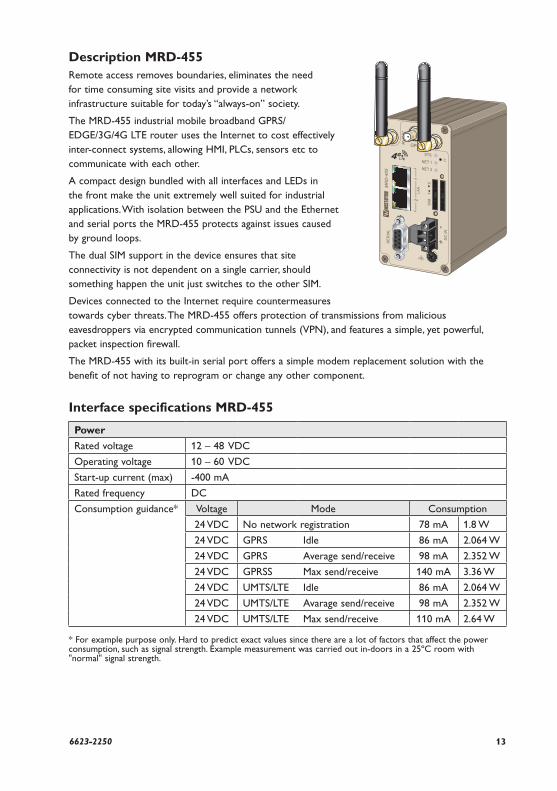
Description MRD-455Remote access removes boundaries, eliminates the need for time consuming site visits and provide a network infrastructure suitable for today’s “always-on” society.
The MRD-455 industrial mobile broadband GPRS/EDGE/3G/4G LTE router uses the Internet to cost effectively inter-connect systems, allowing HMI, PLCs, sensors etc to communicate with each other.
A compact design bundled with all interfaces and LEDs in the front make the unit extremely well suited for industrial applications. With isolation between the PSU and the Ethernet and serial ports the MRD-455 protects against issues caused by ground loops.
The dual SIM support in the device ensures that site connectivity is not dependent on a single carrier, should something happen the unit just switches to the other SIM.
Devices connected to the Internet require countermeasures towards cyber threats. The MRD-455 offers protection of transmissions from malicious eavesdroppers via encrypted communication tunnels (VPN), and features a simple, yet powerful, packet inspection firewall.
The MRD-455 with its built-in serial port offers a simple modem replacement solution with the benefit of not having to reprogram or change any other component.
Interface specifications MRD-455
Power
Rated voltage 12 – 48 VDC
Operating voltage 10 – 60 VDC
Start-up current (max) -400 mA
Rated frequency DC
Consumption guidance* Voltage Mode Consumption
24 VDC No network registration 78 mA 1.8 W
24 VDC GPRS Idle 86 mA 2.064 W
24 VDC GPRS Average send/receive 98 mA 2.352 W
24 VDC GPRSS Max send/receive 140 mA 3.36 W
24 VDC UMTS/LTE Idle 86 mA 2.064 W
24 VDC UMTS/LTE Avarage send/receive 98 mA 2.352 W
24 VDC UMTS/LTE Max send/receive 110 mA 2.64 W
* For example purpose only. Hard to predict exact values since there are a lot of factors that affect the power consumption, such as signal strength. Example measurement was carried out in-doors in a 25ºC room with "normal" signal strength.
14 6623-2250
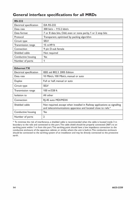
General interface specifications for all MRDs
RS-232
Electrical specification EIA RS-232
Data rate 300 bit/s – 115.2 kbit/s
Data format 7 or 8 data bits, Odd, even or none parity, 1 or 2 stop bits
Protocol Transparent, optimised by packing algorithm
Circuit type SELV
Transmission range 15 m/49 ft
Connection 9 pin D-sub female
Shielded cable Not required
Conductive housing Yes
Number of ports 1
Ethernet TX
Electrical specification IEEE std 802.3. 2005 Edition
Data rate 10 Mbit/s, 100 Mbit/s, manual or auto
Duplex Full or half, manual or auto
Circuit type SELV
Transmission range 100 m/328 ft
Isolation to All other
Connection RJ-45 auto MDI/MDIX
Shielded cable Not required, except when installed in Railway applications as signalling and telecommunications apparatus and located close to rails.*
Conductive housing Yes
Number of ports 2
* To minimise the risk of interference, a shielded cable is recommended when the cable is located inside 3 m boundary to the rails and connected to this port. The cable shield should be properly connected (360º) to an earthing point within 1 m from this port. This earthing point should have a low impedance connection to the conductive enclosure of the apparatus cabinet, or similar, where the unit is built-in. This conductive enclosure should be connected to the earthing system of an installation and may be directly connected to the protective earth.
156623-2250
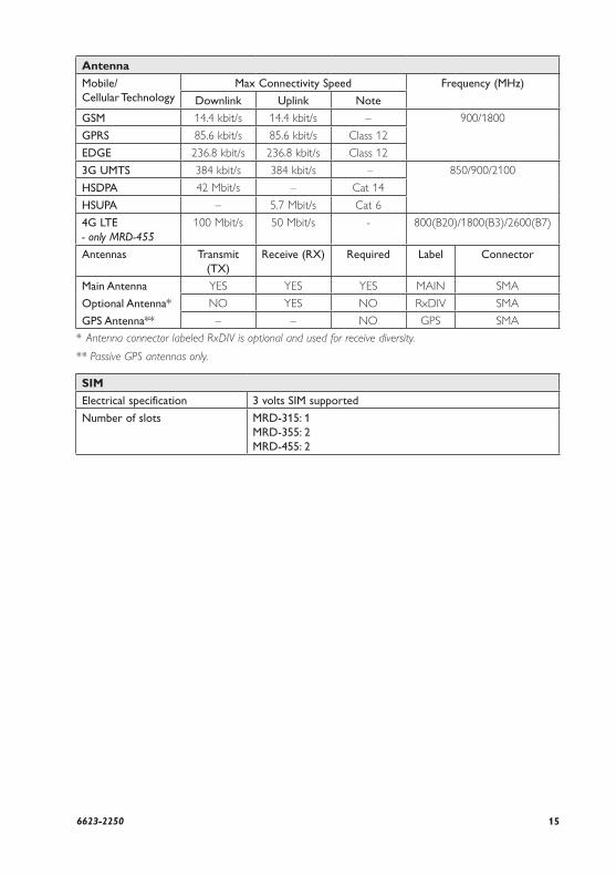
Antenna
Mobile/ Cellular Technology
Max Connectivity Speed Frequency (MHz)
Downlink Uplink Note
GSM 14.4 kbit/s 14.4 kbit/s – 900/1800
GPRS 85.6 kbit/s 85.6 kbit/s Class 12
EDGE 236.8 kbit/s 236.8 kbit/s Class 12
3G UMTS 384 kbit/s 384 kbit/s – 850/900/2100
HSDPA 42 Mbit/s – Cat 14
HSUPA – 5.7 Mbit/s Cat 6
4G LTE - only MRD-455
100 Mbit/s 50 Mbit/s - 800(B20)/1800(B3)/2600(B7)
Antennas Transmit (TX)
Receive (RX) Required Label Connector
Main Antenna
Optional Antenna*
GPS Antenna**
YES YES YES MAIN SMA
NO YES NO RxDIV SMA
– – NO GPS SMA
* Antenna connector labeled RxDIV is optional and used for receive diversity.
** Passive GPS antennas only.
SIM
Electrical specification 3 volts SIM supported
Number of slots MRD-315: 1MRD-355: 2MRD-455: 2
16 6623-2250
SIM card drawer eject button
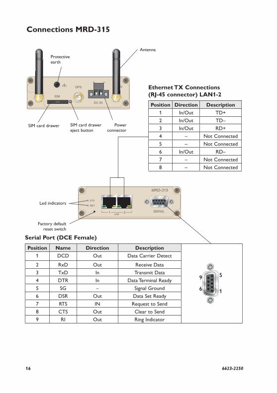
Connections MRD-315
Serial Port (DCE Female)
Position Name Direction Description
5
1
9
6
1 DCD Out Data Carrier Detect
2 RxD Out Receive Data
3 TxD In Transmit Data
4 DTR In Data Terminal Ready
5 SG – Signal Ground
6 DSR Out Data Set Ready
7 RTS IN Request to Send
8 CTS Out Clear to Send
9 RI Out Ring Indicator
Led indicators
Antenna
Protective earth
SIM card drawer Power connector
Ethernet TX Connections (RJ-45 connector) LAN1-2
Position Direction Description
1 In/Out TD+
2 In/Out TD–
3 In/Out RD+
4 – Not Connected
5 – Not Connected
6 In/Out RD–
7 – Not Connected
8 – Not Connected
Factory default reset switch
176623-2250
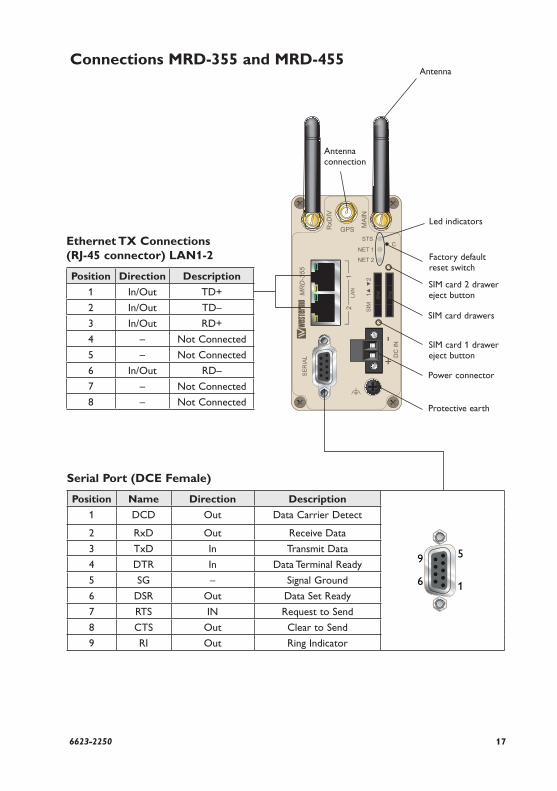
SIM card 2 drawer eject button
Connections MRD-355 and MRD-455
Serial Port (DCE Female)
Position Name Direction Description
5
1
9
6
1 DCD Out Data Carrier Detect
2 RxD Out Receive Data
3 TxD In Transmit Data
4 DTR In Data Terminal Ready
5 SG – Signal Ground
6 DSR Out Data Set Ready
7 RTS IN Request to Send
8 CTS Out Clear to Send
9 RI Out Ring Indicator
Led indicators
Antenna
Protective earth
SIM card drawers
Factory default reset switch
Power connector
SIM card 1 drawer eject button
Ethernet TX Connections (RJ-45 connector) LAN1-2
Position Direction Description
1 In/Out TD+
2 In/Out TD–
3 In/Out RD+
4 – Not Connected
5 – Not Connected
6 In/Out RD–
7 – Not Connected
8 – Not Connected
Antenna connection
18 6623-2250
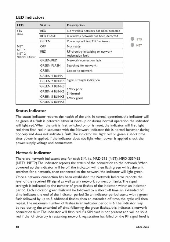
LED Indicators
LED Status Description
STS Status
RED No wireless network has been detected
RED FLASH A wireless network has been detected
GREEN Power up self test OK/no issues
NET NET 1 NET 2 Network indicator
OFF Not ready
RED RF circuitry initialising or network registration fault
GREEN/RED Network connection fault
GREEN FLASH Searching for network
GREEN Locked to network
GREEN 1 BLINKSignal strength indication
1 Very poor3 Normal6 Very good
GREEN 2 BLINKS
GREEN 3 BLINKS
GREEN 4 BLINKS
GREEN 5 BLINKS
GREEN 6 BLINKS
Status Indicator The status indicator reports the health of the unit. In normal operation, the indicator will be green, if a fault is detected either at boot-up or during normal operation the indicator will light red. When the unit is first switched on or is reset, the indicator will first light red, then flash red in sequence with the Network Indicator, this is normal behavior during boot-up and does not indicate a fault. The indicator will light red or green a short time after power is applied. If the indicator does not light when power is applied check the power supply voltage and connections.
Network Indicator There are network indicators one for each SIM, i.e. MRD-315 (NET), MRD-355/455 (NET1, NET2) The indicator reports the status of the connection to the network. When powered up the indicator will be off, the indicator will then flash green whilst the unit searches for a network, once connected to the network the indicator will light green.
Once a network connection has been established the Network Indicator reports the level of the received RF signal as well as any network connection faults. The signal strength is indicated by the number of green flashes of the indicator within an indicator period. Each indicator green flash will be followed by a short off time, an extended off time indicates the end of the indicator period. So an indicator period starts with a green flash followed by up to 5 additional flashes, then an extended off time, the cycle will then repeat. The maximum number of flashes in an indicator period is 6. The indicator may be red during the extended off time following the green flashes, this indicates a network connection fault. The indicator will flash red if a SIM card is not present and will be solid red if the RF circuitry is restarting, network registration has failed or the RF signal level is
196623-2250
too low for a connection.
When the unit is first switched on, or is reset the indicator will first light red, then flash red in sequence with the Status Indicator, this is normal behavior during boot-up and does not indicate a fault.
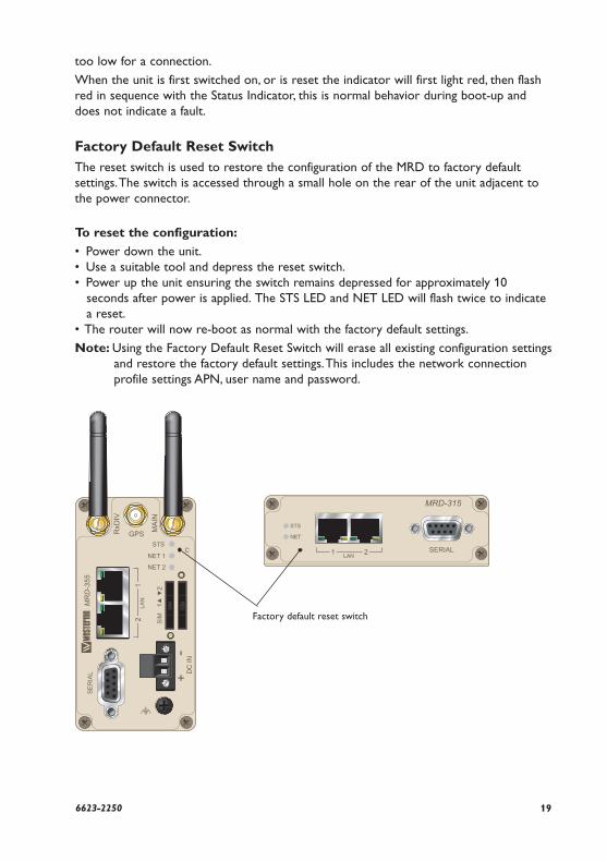
Factory Default Reset SwitchThe reset switch is used to restore the configuration of the MRD to factory default settings. The switch is accessed through a small hole on the rear of the unit adjacent to the power connector.
To reset the configuration:
• Power down the unit.• Use a suitable tool and depress the reset switch.• Power up the unit ensuring the switch remains depressed for approximately 10
seconds after power is applied. The STS LED and NET LED will flash twice to indicate a reset.
• The router will now re-boot as normal with the factory default settings.
Note: Using the Factory Default Reset Switch will erase all existing configuration settings and restore the factory default settings. This includes the network connection profile settings APN, user name and password.
Factory default reset switch
20 6623-2250
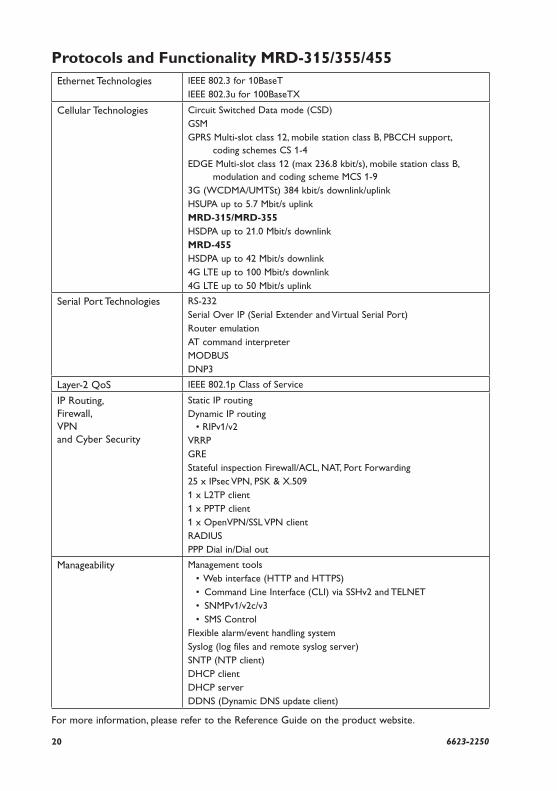
Protocols and Functionality MRD-315/355/455Ethernet Technologies IEEE 802.3 for 10BaseT
IEEE 802.3u for 100BaseTX
Cellular Technologies Circuit Switched Data mode (CSD)GSM GPRS Multi-slot class 12, mobile station class B, PBCCH support, coding schemes CS 1-4EDGE Multi-slot class 12 (max 236.8 kbit/s), mobile station class B, modulation and coding scheme MCS 1-93G (WCDMA/UMTSt) 384 kbit/s downlink/uplinkHSUPA up to 5.7 Mbit/s uplinkMRD-315/MRD-355HSDPA up to 21.0 Mbit/s downlinkMRD-455HSDPA up to 42 Mbit/s downlink4G LTE up to 100 Mbit/s downlink4G LTE up to 50 Mbit/s uplink
Serial Port Technologies RS-232Serial Over IP (Serial Extender and Virtual Serial Port)Router emulationAT command interpreterMODBUSDNP3
Layer-2 QoS IEEE 802.1p Class of Service
IP Routing, Firewall, VPN and Cyber Security
Static IP routingDynamic IP routing • RIPv1/v2VRRPGREStateful inspection Firewall/ACL, NAT, Port Forwarding25 x IPsec VPN, PSK & X.5091 x L2TP client1 x PPTP client1 x OpenVPN/SSL VPN clientRADIUSPPP Dial in/Dial out
Manageability Management tools • Web interface (HTTP and HTTPS) • Command Line Interface (CLI) via SSHv2 and TELNET • SNMPv1/v2c/v3 • SMS ControlFlexible alarm/event handling systemSyslog (log files and remote syslog server)SNTP (NTP client)DHCP clientDHCP serverDDNS (Dynamic DNS update client)
For more information, please refer to the Reference Guide on the product website.
216623-2250
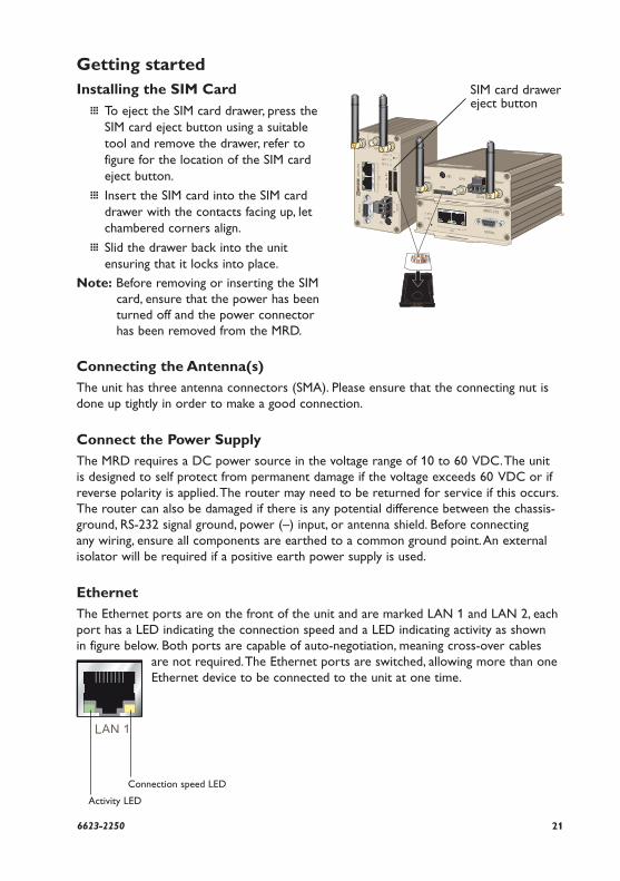
Getting startedInstalling the SIM Card
… To eject the SIM card drawer, press the SIM card eject button using a suitable tool and remove the drawer, refer to figure for the location of the SIM card eject button.
… Insert the SIM card into the SIM card drawer with the contacts facing up, let chambered corners align.
… Slid the drawer back into the unit ensuring that it locks into place.
Note: Before removing or inserting the SIM card, ensure that the power has been turned off and the power connector has been removed from the MRD.
Connecting the Antenna(s)The unit has three antenna connectors (SMA). Please ensure that the connecting nut is done up tightly in order to make a good connection.
Connect the Power SupplyThe MRD requires a DC power source in the voltage range of 10 to 60 VDC. The unit is designed to self protect from permanent damage if the voltage exceeds 60 VDC or if reverse polarity is applied. The router may need to be returned for service if this occurs. The router can also be damaged if there is any potential difference between the chassis-ground, RS-232 signal ground, power (–) input, or antenna shield. Before connecting any wiring, ensure all components are earthed to a common ground point. An external isolator will be required if a positive earth power supply is used.
EthernetThe Ethernet ports are on the front of the unit and are marked LAN 1 and LAN 2, each port has a LED indicating the connection speed and a LED indicating activity as shown in figure below. Both ports are capable of auto-negotiation, meaning cross-over cables
are not required. The Ethernet ports are switched, allowing more than one Ethernet device to be connected to the unit at one time.
Activity LED
Connection speed LED
SIM card drawer eject button
22 6623-2250
Configuration Accessing and Using the Web Interface
All configuration of the MRD can be done via the web interface. In order to view the web pages a computer with a fixed IP address, on the same sub-net as the MRD, will need to be connected to one of the LAN ports.
The default IP settings of the MRD are:
• IP Address: 192.168.2.200 • Netmask: 255.255.255.0
The recommended IP settings for the PC used to configure the MRD Router:
• IP Address: 192.168.2.100• Netmask: 255.255.255.0• Default Gateway: 192.168.2.200• Primary DNS: 192.168.2.200
Note: Although it is possible to connect the MRD directly to a Local Area Network (LAN) it is recommend that the network configuration as described in this section is performed prior to doing so. The DHCP server of the unit is by default disabled.
Windows PC Network Settings
The following describes how to configure the network settings of a Windows PC so that it can access the MRD.
Note: This procedure will change the network settings of the Windows PC, if the PC is connected to a network the connection should be removed before performing the changes. To restore the network, settings of the PC record the current settings at Step 6 in the following procedure, then when the MRD has been configured, follow the procedure again and use the recorded values at Step 6.
1. Open the Control Panel by selecting Start > Control Panel.
2. Double click the Network Connections icon.
3. Double click the Network icon.
4. The Local Area Connection Status dialog box will be displayed, click the Properties button.
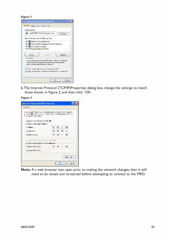
5. The Local Area Connection Properties dialog box, as shown in Figure 1, will be displayed Click on Internet Protocol (TCP/IP) to highlight it and then click the Properties button.
236623-2250
Figure 1
6. The Internet Protocol (TCP/IP)Properties dialog box, change the settings to match those shown in Figure 2, and then click ”OK.
Figure 2
Note: If a web browser was open prior to making the network changes, then it will need to be closed and re-started before attempting to connect to the MRD.
24 6623-2250
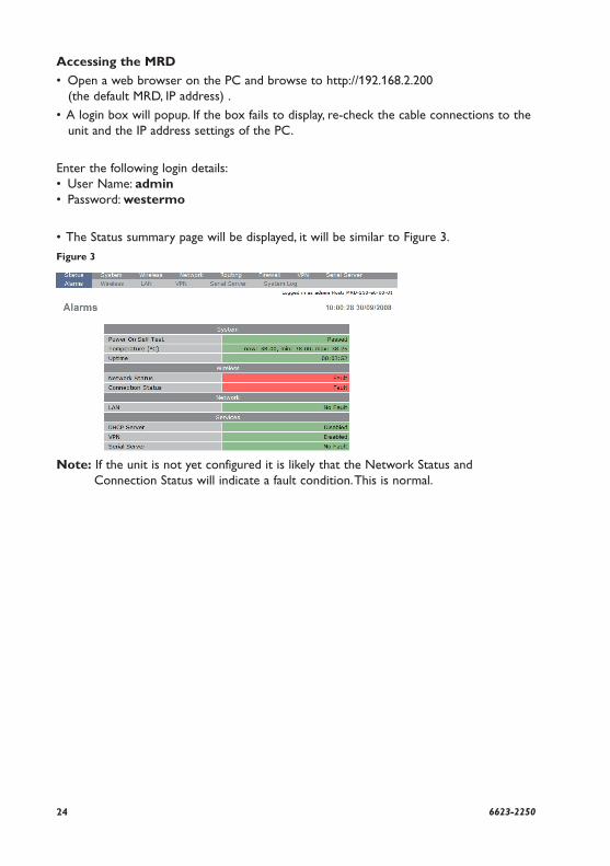
Accessing the MRD
• Open a web browser on the PC and browse to http://192.168.2.200 (the default MRD, IP address) .
• A login box will popup. If the box fails to display, re-check the cable connections to the unit and the IP address settings of the PC.
Enter the following login details:• User Name: admin• Password: westermo
• The Status summary page will be displayed, it will be similar to Figure 3.
Figure 3
Note: If the unit is not yet configured it is likely that the Network Status and Connection Status will indicate a fault condition. This is normal.
256623-2250
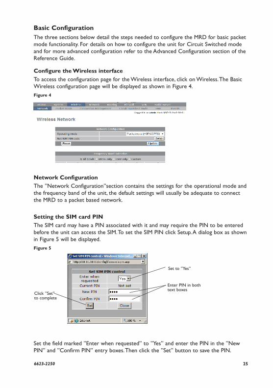
Basic ConfigurationThe three sections below detail the steps needed to configure the MRD for basic packet mode functionality. For details on how to configure the unit for Circuit Switched mode and for more advanced configuration refer to the Advanced Configuration section of the Reference Guide.
Configure the Wireless interface
To access the configuration page for the Wireless interface, click on Wireless. The Basic Wireless configuration page will be displayed as shown in Figure 4.
Figure 4
Network Configuration
The ”Network Configuration”section contains the settings for the operational mode and the frequency band of the unit, the default settings will usually be adequate to connect the MRD to a packet based network.
Setting the SIM card PIN
The SIM card may have a PIN associated with it and may require the PIN to be entered before the unit can access the SIM. To set the SIM PIN click Setup. A dialog box as shown in Figure 5 will be displayed.
Figure 5
Set the field marked ”Enter when requested” to ”Yes” and enter the PIN in the ”New PIN” and ”Confirm PIN” entry boxes. Then click the ”Set” button to save the PIN.
Click ”Set” to complete
Set to ”Yes”
Enter PIN in both text boxes
26 6623-2250
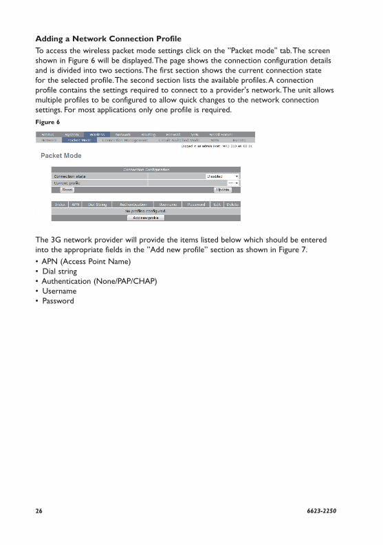
Adding a Network Connection Profile
To access the wireless packet mode settings click on the ”Packet mode'' tab. The screen shown in Figure 6 will be displayed. The page shows the connection configuration details and is divided into two sections. The first section shows the current connection state for the selected profile. The second section lists the available profiles. A connection profile contains the settings required to connect to a provider's network. The unit allows multiple profiles to be configured to allow quick changes to the network connection settings. For most applications only one profile is required.
Figure 6
The 3G network provider will provide the items listed below which should be entered into the appropriate fields in the ”Add new profile” section as shown in Figure 7.
• APN (Access Point Name) • Dial string • Authentication (None/PAP/CHAP)• Username• Password
276623-2250
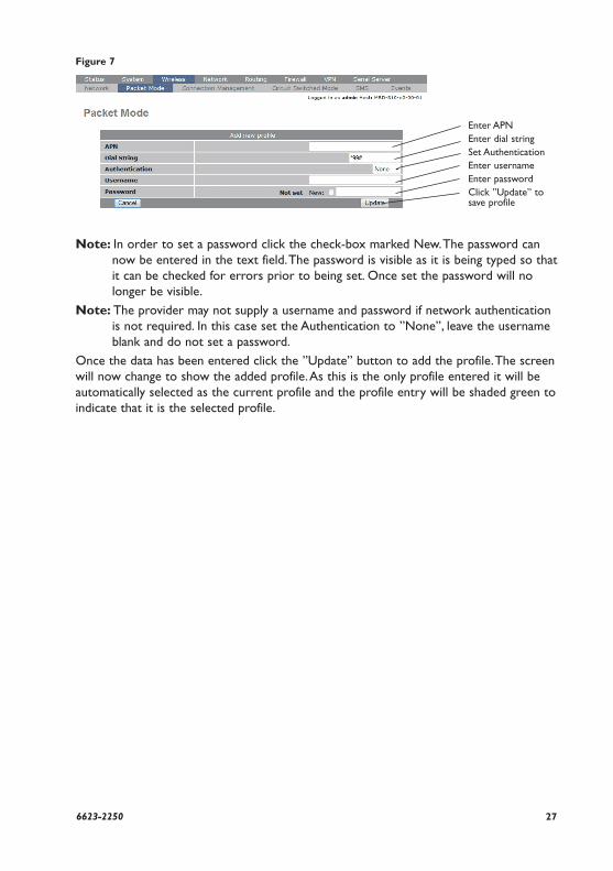
Figure 7
Note: In order to set a password click the check-box marked New. The password can now be entered in the text field. The password is visible as it is being typed so that it can be checked for errors prior to being set. Once set the password will no longer be visible.
Note: The provider may not supply a username and password if network authentication is not required. In this case set the Authentication to ”None”, leave the username blank and do not set a password.
Once the data has been entered click the ”Update” button to add the profile. The screen will now change to show the added profile. As this is the only profile entered it will be automatically selected as the current profile and the profile entry will be shaded green to indicate that it is the selected profile.
Enter APNEnter dial stringSet AuthenticationEnter usernameEnter passwordClick ”Update” to save profile
28 6623-2250
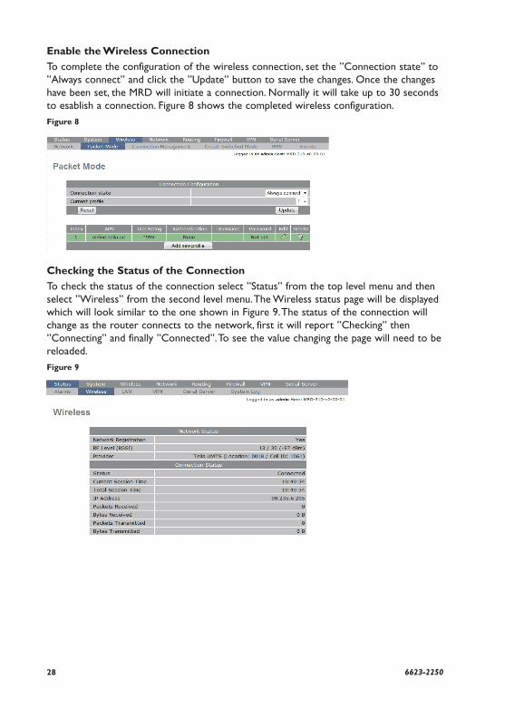
Enable the Wireless Connection
To complete the configuration of the wireless connection, set the ”Connection state” to ”Always connect” and click the ”Update” button to save the changes. Once the changes have been set, the MRD will initiate a connection. Normally it will take up to 30 seconds to esablish a connection. Figure 8 shows the completed wireless configuration.
Figure 8
Checking the Status of the Connection
To check the status of the connection select ”Status” from the top level menu and then select ”Wireless” from the second level menu. The Wireless status page will be displayed which will look similar to the one shown in Figure 9. The status of the connection will change as the router connects to the network, first it will report ”Checking” then ”Connecting” and finally ”Connected”. To see the value changing the page will need to be reloaded.
Figure 9
296623-2250
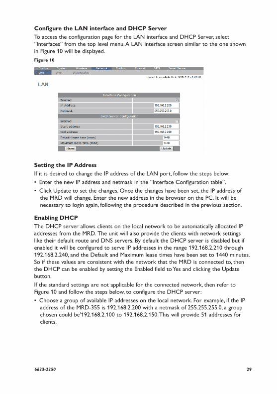
Configure the LAN interface and DHCP Server
To access the configuration page for the LAN interface and DHCP Server, select ”Interfaces” from the top level menu. A LAN interface screen similar to the one shown in Figure 10 will be displayed.
Figure 10
Setting the IP Address
If it is desired to change the IP address of the LAN port, follow the steps below:
• Enter the new IP address and netmask in the ”Interface Configuration table”.
• Click Update to set the changes. Once the changes have been set, the IP address of the MRD will change. Enter the new address in the browser on the PC. It will be necessary to login again, following the procedure described in the previous section.
Enabling DHCP
The DHCP server allows clients on the local network to be automatically allocated IP addresses from the MRD. The unit will also provide the clients with network settings like their default route and DNS servers. By default the DHCP server is disabled but if enabled it will be configured to serve IP addresses in the range 192.168.2.210 through 192.168.2.240, and the Default and Maximum lease times have been set to 1440 minutes. So if these values are consistent with the network that the MRD is connected to, then the DHCP can be enabled by setting the Enabled field to Yes and clicking the Update button.
If the standard settings are not applicable for the connected network, then refer to Figure 10 and follow the steps below, to configure the DHCP server:
• Choose a group of available IP addresses on the local network. For example, if the IP address of the MRD-355 is 192.168.2.200 with a netmask of 255.255.255.0, a group chosen could be’192.168.2.100 to 192.168.2.150. This will provide 51 addresses for clients.
30 6623-2250
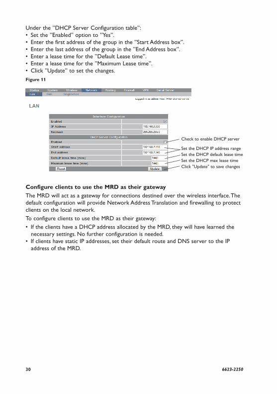
Under the ”DHCP Server Configuration table”:• Set the ”Enabled” option to ”Yes”.• Enter the first address of the group in the ”Start Address box”.• Enter the last address of the group in the ”End Address box”.• Enter a lease time for the ”Default Lease time”. • Enter a lease time for the ”Maximum Lease time”.• Click ”Update” to set the changes.
Figure 11
Configure clients to use the MRD as their gateway
The MRD will act as a gateway for connections destined over the wireless interface. The default configuration will provide Network Address Translation and firewalling to protect clients on the local network.
To configure clients to use the MRD as their gateway:
• If the clients have a DHCP address allocated by the MRD, they will have learned the necessary settings. No further configuration is needed.
• If clients have static IP addresses, set their default route and DNS server to the IP address of the MRD.
Check to enable DHCP server
Set the DHCP IP address rangeSet the DHCP default lease timeSet the DHCP max lease timeClick "Update" to save changes
316623-2250
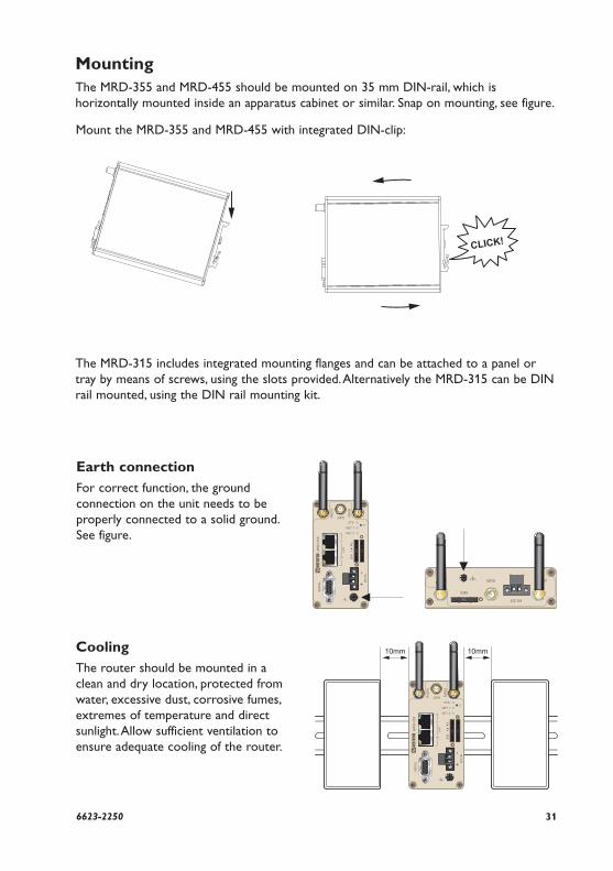
CoolingThe router should be mounted in a clean and dry location, protected from water, excessive dust, corrosive fumes, extremes of temperature and direct sunlight. Allow sufficient ventilation to ensure adequate cooling of the router.
10mm 10mm
MountingThe MRD-355 and MRD-455 should be mounted on 35 mm DIN-rail, which is horizontally mounted inside an apparatus cabinet or similar. Snap on mounting, see figure.
Mount the MRD-355 and MRD-455 with integrated DIN-clip:
The MRD-315 includes integrated mounting flanges and can be attached to a panel or tray by means of screws, using the slots provided. Alternatively the MRD-315 can be DIN rail mounted, using the DIN rail mounting kit.
Earth connectionFor correct function, the ground connection on the unit needs to be properly connected to a solid ground. See figure.
32 6623-2250
Dimensions MRD-315Measurements are stated in millimeters.
124
33
3
104
15
154
2
40 40
103
135 142
50
R8
R8
R4
22
3
336623-2250
Dimensions MRD-355 and MRD-455Measurements are stated in millimeters.
9210
36
103
53
REV. C 6623-2250 2016-02 Westermo Teleindustri AB, Sweden – A Beijer Electronics Group Company
For complete contact information, please visit our website at www.westermo.com/contact or scan the QR code
China [email protected] www.cn.westermo.com
France [email protected] www.westermo.fr
Germany [email protected] www.westermo.de
North America [email protected] www.westermo.com
Singapore [email protected] www.westermo.com
Sweden [email protected] www.westermo.se
United Kingdom [email protected] www.westermo.co.uk
Other Offices
Sales UnitsWestermo Data Communications
Westermo • SE-640 40 Stora Sundby, SwedenTel +46 16 42 80 00 Fax +46 16 42 80 01
E-mail: [email protected] www.westermo.com