Embed Size (px)
Citation preview

MRC Generator System Selection Guide Revision 1.8
© 2012 Millennial Research Corporation Page 1
MRC Power Generator Division
Generator System Base Component Selection Guide
Revision 1.8
Revision Date: 5/8/3012
NOTE: This document is provided by MRC Engineering as a guideline for internal component
selection, engineering, procurement, costing & fabrication departments. Cost estimates
included in the selection tables are estimates based on quotes received within the last 30 days
and are subject to change. Site specific requirements may mandate additional equipment not
part of this platform specification process that will affect final cost.
PROPRIETARY INFORMATION
This document contains MRC cost information and
is not to be distributed outside MRC. The data
contained within is for MRC internal use only.

MRC Generator System Selection Guide Revision 1.8
© 2012 Millennial Research Corporation Page 2
Contents
Introduction .................................................................................................................................................. 3
Generator System Configuration Guidelines ................................................................................................ 4
Power Output Range Selection ................................................................................................................. 4
Gen‐Set Control Unit Selection ................................................................................................................. 5
AC Power Output Option Selection .......................................................................................................... 5
VFD (PWM) Type Power Conversion (Inverters) ................................................................................... 6
TRUESINE™ Power Conversion (Grid‐Tie and True Sinusoidal) ............................................................ 6
Generator‐Engine Matching ..................................................................................................................... 7
Natural Gas @ Low Elevation (Less than 7000 FT) ............................................................................... 8
Natural Gas @ High Elevation (7000 FT or higher) ............................................................................... 8
Summary ....................................................................................................................................................... 9
Appendix A .................................................................................................................................................. 10
Example Worksheet #1 ........................................................................................................................... 10
Appendix B .................................................................................................................................................. 13

MRC Generator System Selection Guide Revision 1.8
© 2012 Millennial Research Corporation Page 3
Introduction
MRC generator systems are on mobile platforms and focused on the prime power market where us of
alternative fuels brings economic benefit to the customer. This guide focuses on natural gas fueled
generation systems for prime power.
To create a prime power system, the MRC 15X series load following generators are combined with a
durable natural gas fueled engine to provide a self‐contained electric generation platform for prime
power1 applications. A mobile or stationary platform can be constructed with the appropriate engine
and MRC generator and power output options. This guide will assist you in selecting the correct
components for a particular application and determining the estimated cost of the final system for that
application.
The MRC prime power generation system is constructed with the engine‐generator combination in a
self‐contained unit with or without an overall enclosure. With no overall enclosure, the MRC generator
is covered with a small cover or housing to keep out direct environmental elements. This small
generator cover is not required if the overall enclosure is used. The application will determine if the
overall enclosure is required, or the overall enclosure may be considered a required option for certain
applications. In additions to the engine‐generator self‐contained unit, a separate electronics enclosure
with independent stand or mounting system is constructed. This enclosure contains the generator gen‐
set control unit, power conversion (inverter) unit, and any other equipment like satellite monitoring or
industrial control interfaces to the customer external systems. At a minimum, the gen‐set controller and
some power conversion is usually required. Figure 1 shows a diagram of the base system unit and
components for a typical system.
Figure 1 ‐ Overview of typical power generator system
1 Prime Power applications are those for which power is generated constantly or on a 24/7 schedule.
Engine
Generator
Frame
Optional Skid or DOT Approved Trailer
Optional Overall Enclosure
Electronics Enclosure
(Gen‐Set Control +
Inverter + Filters +
Other)
MRC Generator System Selection Guide Revision 1.8
© 2012 Millennial Research Corporation Page 4
GeneratorSystemConfigurationGuidelines
The following sections of this guide contain the recommended engine‐to‐generator matching based on
MRC engineering specifications. It is to be used to select and configure a typical prime power system for
a particular application. Refer to it as your basic guide for most prime power applications. It also
contains the latest cost estimates, so it can be used to quickly estimate the total base system cost for
any particular power range of applications. Appendix A contains sample worksheets for several typical
applications as a reference on using the data in the tables included in this guide.
NOTE: All estimated costs in this guide are based on the most recent quotes and estimates. See
appendix B for a summary table of components and quotes. All estimates are subject to change. Use the
estimates to get a rough idea of the total cost of a system based on the selection criteria as determined
by the application.
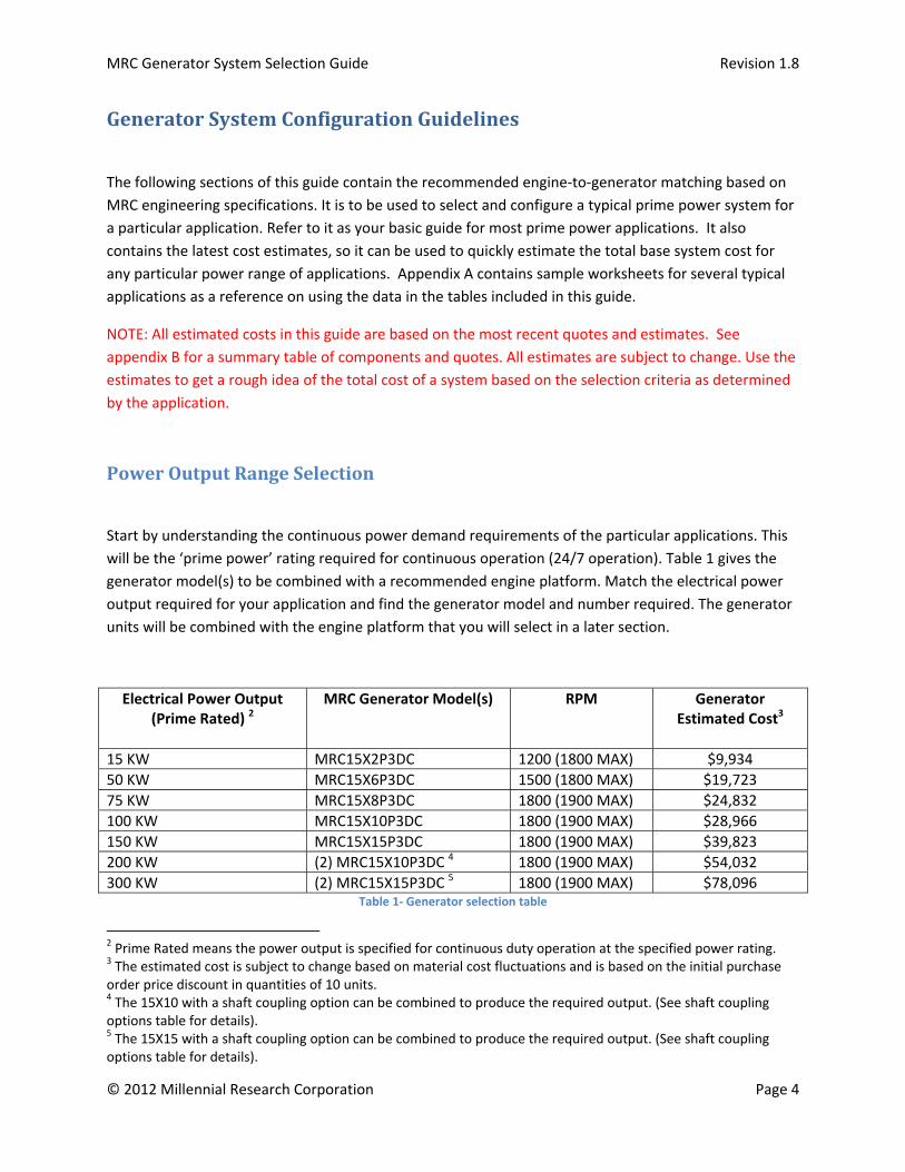
PowerOutputRangeSelection
Start by understanding the continuous power demand requirements of the particular applications. This
will be the ‘prime power’ rating required for continuous operation (24/7 operation). Table 1 gives the
generator model(s) to be combined with a recommended engine platform. Match the electrical power
output required for your application and find the generator model and number required. The generator
units will be combined with the engine platform that you will select in a later section.
Electrical Power Output (Prime Rated) 2
MRC Generator Model(s) RPM Generator Estimated Cost3
15 KW MRC15X2P3DC 1200 (1800 MAX) $9,934
50 KW MRC15X6P3DC 1500 (1800 MAX) $19,723
75 KW MRC15X8P3DC 1800 (1900 MAX) $24,832
100 KW MRC15X10P3DC 1800 (1900 MAX) $28,966
150 KW MRC15X15P3DC 1800 (1900 MAX) $39,823
200 KW (2) MRC15X10P3DC 4 1800 (1900 MAX) $54,032
300 KW (2) MRC15X15P3DC 5 1800 (1900 MAX) $78,096 Table 1‐ Generator selection table
2 Prime Rated means the power output is specified for continuous duty operation at the specified power rating. 3 The estimated cost is subject to change based on material cost fluctuations and is based on the initial purchase order price discount in quantities of 10 units. 4 The 15X10 with a shaft coupling option can be combined to produce the required output. (See shaft coupling options table for details). 5 The 15X15 with a shaft coupling option can be combined to produce the required output. (See shaft coupling options table for details).

MRC Generator System Selection Guide Revision 1.8
© 2012 Millennial Research Corporation Page 5
MRC Generator Model(s) MRC Shaft Coupling and Mounting Kit
MRC15X10P3DC MRC‐CPLK‐15X10
MRC15X15P3DC MRC‐CPLK‐15X15 Table 2‐ Shaft coupling kit table
Gen‐SetControlUnitSelection
Every generator must have a gen‐set control unit (GSCU) and associated power bus assembly. This
control unit mates and interfaces with any of the engine platforms recommended in engine selection
table. Match the highest capacity generator that will be used in your configuration and select the gen‐
set unit required from Table 3 below. Note that if two generators are used, as in the 300 KW case, only
one GSCU is required.
MRC Generator Model(s) GSCU Model GSCU & Bus Assembly Estimated Cost
MRC15X2P3DC MRC‐GS‐15X2 $1,300
MRC15X6P3DC MRC‐GS‐15X6 $1,700
MRC15X8P3DC MRC‐GS‐15X8 $1,800
MRC15X10P3DC MRC‐GS‐15X10 $2,000
MRC15X15P3DC MRC‐GS‐15X15 $2,250 Table 3 ‐ GSCU selection table
ACPowerOutputOptionSelection
Each MRC generator is a DC generator and the type and voltage rating needed for each application
requires a ‘power conversion and normalization’ unit. The primary market is for oil field application that
can tolerate ‘non pure sinusoidal’ power. This is any inductive or limited lighting application that can use
a PWM based inverter or variable frequency drive. The ‘power conversion and correction’ unit has been
engineered and matched to each MRC generator for use in driving pumps, fans, and industrial lighting.
In some applications, filters and sinusoidal correction may be required. Each application requires a
programming service and final engineering review to determine if the application can be supplied with
the MRC PWM based inverters. In situations where ‘grid‐tie’ or institutional AC power must be
generated, a ‘grid‐tie’ or ‘true sinusoidal’ inverter must be used. This is a ‘special option’ and MRC
should be contacted for pricing and engineering specifics for that type of application.

MRC Generator System Selection Guide Revision 1.8
© 2012 Millennial Research Corporation Page 6
If your application load is industrial with primarily motors and limited lighting, the VFD (PWM) type
inverter can be used. The VFD (PWM) type is typically used to drive a single motor requiring speed
control, but can be used to drive a limited number of motors in some applications. If your application
has several motors, you may need to segment the drive of some motors by selecting multiple VFD type
inverters. If this is done, do not exceed the total output capacity of the generator that you selected from
Table 1. Using Table 4 or Table 5 , identify the prime rated power output, load type, phase, and voltage
requirement for the application, then select the MRC inverter model to be ‘paired’ with the MRC
generator selected earlier. Use Table 6 to select a VFD filter options when using the VFD type inverter.
The filter is needed to correct for non‐inductive or non‐motor loads, like lighting and other resistive
loads.
VFD(PWM)TypePowerConversion(Inverters)
AC Electrical Power Output (Prime Rated)
MRC Inverter Type6 / Phase/ Voltage
MRC Inverter Model Inverter Estimated Cost
15 KVA VFD (PWM) / 1ф / 240 MRC‐VPI‐20‐1P‐240 $ 2,900
50 KVA VFD (PWM) / 1ф / 240 MRC‐VPI‐60‐1P‐240 $ 4,900
75 KVA VFD (PWM) / 3ф / 480 MRC‐VPI‐75‐3P‐480 $ 5,600
100 KVA VFD (PWM) / 3ф / 480 MRC‐VPI‐115‐3P‐480 $ 6,875
150 KVA VFD (PWM) / 3ф / 480 MRC‐VPI‐150‐3P‐480 $ 8,936
200 KVA VFD (PWM) / 3ф / 480 MRC‐VPI‐225‐3P‐480 $ 10,400
300 KVA VFD (PWM) / 3ф / 480 MRC‐VPI‐325‐3P‐480 $ 14,350 Table 4 ‐ Inverter selection table (VFD/PWM)
TRUESINE™PowerConversion(Grid‐TieandTrueSinusoidal)
AC Electrical Power Output (Prime Rated)
MRC Inverter Type7 / Phase/ Voltage
MRC Inverter Model Inverter Estimated Cost8
15 KVA TRUESINE™ / 1ф / 240 MRC‐TPI‐20‐1P‐240 TBD
50 KVA TRUESINE™ / 1ф / 240 MRC‐TPI‐60‐1P‐240 TBD
75 KVA TRUESINE™ / 3ф / 480 MRC‐TPI‐75‐3P‐480 TBD
6 VFD (PWM) inverters can be used for variable frequency drive of inductive synchronous or asynchronous motors (shunt wound or axial). For limited lighting and inductive motor applications, an optional power correction filter can be installed to provide sinusoidal correction. For institutional applications that supply all types of loads, a true sinusoidal inverter is required. The TRUESINE™ inverter type should be used with a grid‐tie option, if direct grid‐tie is required. 7 TRUESINE™ inverters are not variable frequency and can be used to supply all load types. With the grid‐tie option they can be used for direct grid tie applications. (Additional equipment is required for grid‐tie and each application should be custom engineered and have engineering approval in the local region). 8 TRUESINE™ inverters vary greatly in price and are engineered for each application. Some applications are co‐gen and grid‐tie, or combinations of both. Additional switch and metering gear may be required.

MRC Generator System Selection Guide Revision 1.8
© 2012 Millennial Research Corporation Page 7
100 KVA TRUESINE™ / 3ф / 480 MRC‐TPI‐115‐3P‐480 TBD
150 KVA TRUESINE™ / 3ф / 480 MRC‐TPI‐150‐3P‐480 TBD
200 KVA TRUESINE™ / 3ф / 480 MRC‐TPI‐225‐3P‐480 TBD
300 KVA TRUESINE™ / 3ф / 480 MRC‐TPI‐325‐3P‐480 TBD Table 5 ‐ Inverter selection table (TRUESINE™)
AC Electrical Power Output (Prime Rated)
VFD Output Filter Filter Model Filter Estimated Cost
15 KVA SINEWAVE CORRECTION 1ф MRC‐FIL‐20‐1P‐240 $ 700
50 KVA SINEWAVE CORRECTION 1ф MRC‐ FIL ‐60‐1P‐240 $ 1,800
75 KVA SINEWAVE CORRECTION 3ф MRC‐ FIL ‐75‐3P‐480 $ 2,500
100 KVA SINEWAVE CORRECTION 3ф MRC‐ FIL ‐115‐3P‐480 $ 2,900
150 KVA SINEWAVE CORRECTION 3ф MRC‐ FIL ‐150‐3P‐480 $ 3,900
200 KVA SINEWAVE CORRECTION 3ф MRC‐ FIL ‐225‐3P‐480 $ 5,400
300 KVA SINEWAVE CORRECTION 3ф MRC‐ FIL ‐325‐3P‐480 $ 9,200 Table 6 ‐ VFD Inverter Filter Options Selection
Generator‐EngineMatching
Once the generator model(s), gen‐set, and power correction (inverter) requirements have been
determined and the components selected, they must be integrated into a power‐gen components with
an engine platform. MRC has performed the research and matched all aspects of the MRC generation
system with the industry leading high durability engine platforms from three manufacturers ‐ Arrow,
Cummins, and Waukesha.
The engine platform consists of the engine, radiator assembly, and exhaust, catalyst & emissions
components, and ECU that is required to assemble into a mobile or permanent stand‐alone engine
system9. Once the engine platform is selected, the entire system will be mounted on a base that meets
MRC requirements for generator mounting (length requirements). This base will be manufactured to fit
onto a skid assembly or a DOT approved trailer. Additionally, the base must accommodate an overall
‘enclosure’ that covers the engine and generator components. The ‘power conversion unit’ (inverter)
will be manufactured into a NEMA/UL compliant electrical cabinet according to MRC specifications. This
power conversion unit will be a separately mounted assembly. This cabinet should be mounted on a
frame that will accept mounting onto the wheeled trailer or the skid assembly or skid platform.
Using Table 7 below, find the power output rating for the application and select the engine platform to
be integrated with the MRC generator, gen‐set, and inverter that was previously selected.
9 The Arrow engines include a bottom frame and light duty skid assembly. The Waukesha engines do not include frames.

MRC Generator System Selection Guide Revision 1.8
© 2012 Millennial Research Corporation Page 8
NaturalGas@LowElevation(Lessthan7000FT)
Low elevation engines have a less than 8:1 compression ratio and operate at altitudes of fewer than
6000 to 7000 feet with moderate site tuning. Use high elevation engines for altitudes above 6000 to
7000 feet.
Electrical Power Output
(Prime Rated)
Minimum/Maximum Braking Horsepower
@ flywheel
Minimum/Maximum RPM
Engine Make/Model/Options 10
Engine Estimated
Cost
15 KW 18/27 1200/1800 Arrow/A32 or Arrow/A42
$ 13,667
$ 14,190
50 KW 65/88 1500/1800 Arrow/A62 $ 18,677
75 KW 90/120 1800/1900 Arrow/A62T/Turbo11 $ 23,158
100 KW 133/177 1800/1900 Cummins/G855 $ 61,000
150 KW 221/265 1800/1900 Cummins/GTA855e $ 75,000
200 KW 290/354 1800/1900 Waukesha VGF / F18GSI or
Cummins / KTA19GC
$ 95,192
$ 100,000
300 KW 470/531 1800/1900 Waukesha VGF / H24GSI $ 124,689 Table 7 ‐ Engine selection table (low elevation)
NaturalGas@HighElevation(7000FTorhigher)
High elevation engines have a less than 10:1 compression ratio, pressure condenser modifications,
timing modifications, turbo, and carburetion adjustments designed for high elevations. High elevation
engines can be run in low elevations with tuning, although they tend to be higher priced due to the
additional engine modifications. For the Arrow engines recommended in this document, the high
elevation modifications are built into the base model, therefore, the engines recommended in this table
are used in the low elevation applications, as shown in
10 See appendix B for detailed specifications on the recommended engines. 11 The A62T has an optional full enclosure at an estimated cost of $2,395.

MRC Generator System Selection Guide Revision 1.8
© 2012 Millennial Research Corporation Page 9
Electrical Power Output
(Prime Rated)
Minimum/Maximum Braking Horsepower
@ flywheel
Minimum/Maximum RPM
Engine Make/Model/Options 12
Engine Estimated
Cost
15 KW 18/27 1200/1800 Arrow/A32 or Arrow/A42
$ 13,667
$ 14,190
50 KW 65/88 1500/1800 Arrow/A62 $ 18,677
75 KW 90/120 1800/1900 Arrow/A62T/Turbo13 $ 23,158
100 KW 133/177 1800/1900 Cummins/G855 $ 61,000
150 KW 221/265 1800/1900 Cummins/GTA855e $ 75,000
200 KW 290/354 1800/1900 Waukesha VGF / F18GSI or
Cummins / KTA19GC
$101,141
$ 100,000
300 KW 470/531 1800/1900 Waukesha VGF / H24GSI $ 132,482 Table 8 ‐ Engine selection table (high elevation)
Summary
This document is a guideline on how to select and configure a typical base system for a particular
application. A base system includes the primary components only. Refer to it as your basic guide for
most applications. Appendix A contains sample worksheets for several typical applications.
12 See appendix B for detailed specifications on the recommended engines. 13 The A62T has an optional full enclosure at an estimated cost of $2,395.
MRC Generator System Selection Guide Revision 1.8
© 2012 Millennial Research Corporation Page 10
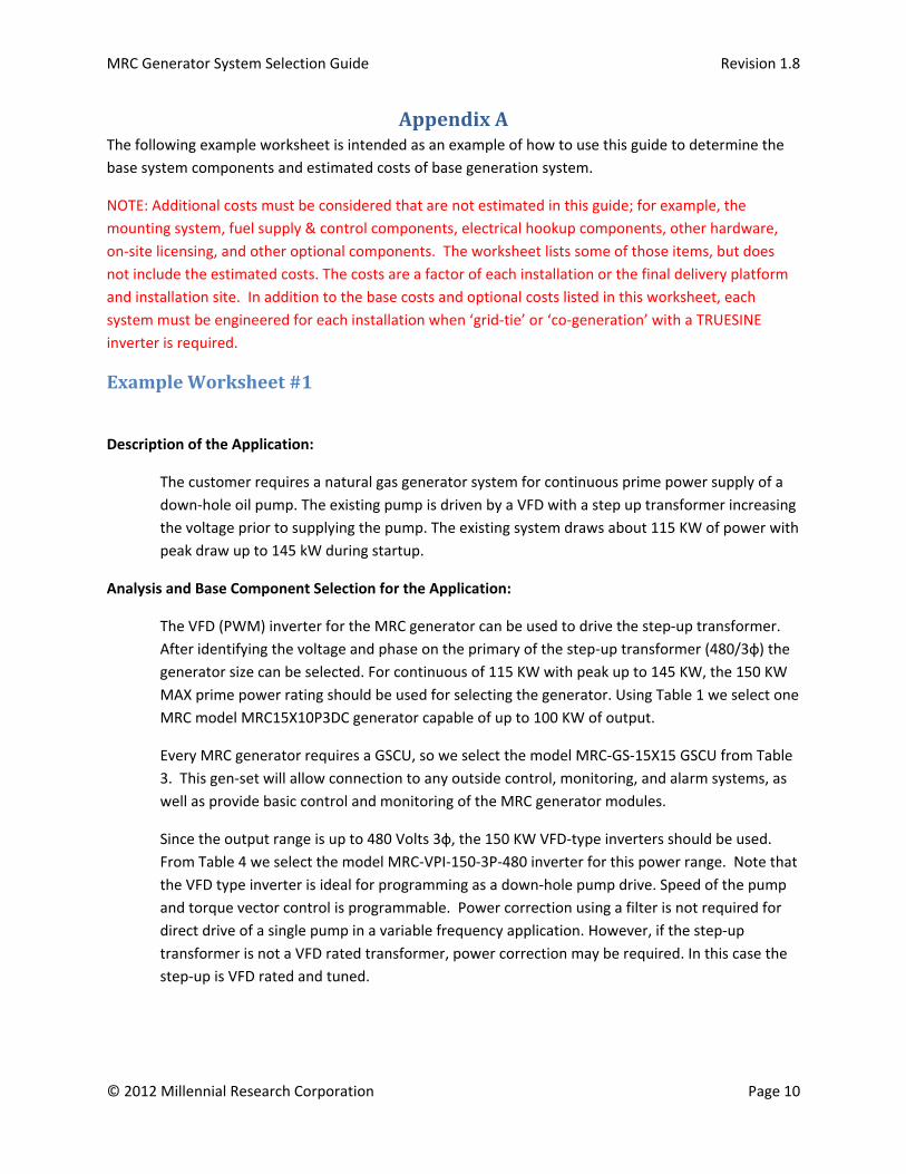
AppendixAThe following example worksheet is intended as an example of how to use this guide to determine the
base system components and estimated costs of base generation system.
NOTE: Additional costs must be considered that are not estimated in this guide; for example, the
mounting system, fuel supply & control components, electrical hookup components, other hardware,
on‐site licensing, and other optional components. The worksheet lists some of those items, but does
not include the estimated costs. The costs are a factor of each installation or the final delivery platform
and installation site. In addition to the base costs and optional costs listed in this worksheet, each
system must be engineered for each installation when ‘grid‐tie’ or ‘co‐generation’ with a TRUESINE
inverter is required.
ExampleWorksheet#1
Description of the Application:
The customer requires a natural gas generator system for continuous prime power supply of a
down‐hole oil pump. The existing pump is driven by a VFD with a step up transformer increasing
the voltage prior to supplying the pump. The existing system draws about 115 KW of power with
peak draw up to 145 kW during startup.
Analysis and Base Component Selection for the Application:
The VFD (PWM) inverter for the MRC generator can be used to drive the step‐up transformer.
After identifying the voltage and phase on the primary of the step‐up transformer (480/3ф) the
generator size can be selected. For continuous of 115 KW with peak up to 145 KW, the 150 KW
MAX prime power rating should be used for selecting the generator. Using Table 1 we select one
MRC model MRC15X10P3DC generator capable of up to 100 KW of output.
Every MRC generator requires a GSCU, so we select the model MRC‐GS‐15X15 GSCU from Table
3. This gen‐set will allow connection to any outside control, monitoring, and alarm systems, as
well as provide basic control and monitoring of the MRC generator modules.
Since the output range is up to 480 Volts 3ф, the 150 KW VFD‐type inverters should be used.
From Table 4 we select the model MRC‐VPI‐150‐3P‐480 inverter for this power range. Note that
the VFD type inverter is ideal for programming as a down‐hole pump drive. Speed of the pump
and torque vector control is programmable. Power correction using a filter is not required for
direct drive of a single pump in a variable frequency application. However, if the step‐up
transformer is not a VFD rated transformer, power correction may be required. In this case the
step‐up is VFD rated and tuned.
MRC Generator System Selection Guide Revision 1.8
© 2012 Millennial Research Corporation Page 11
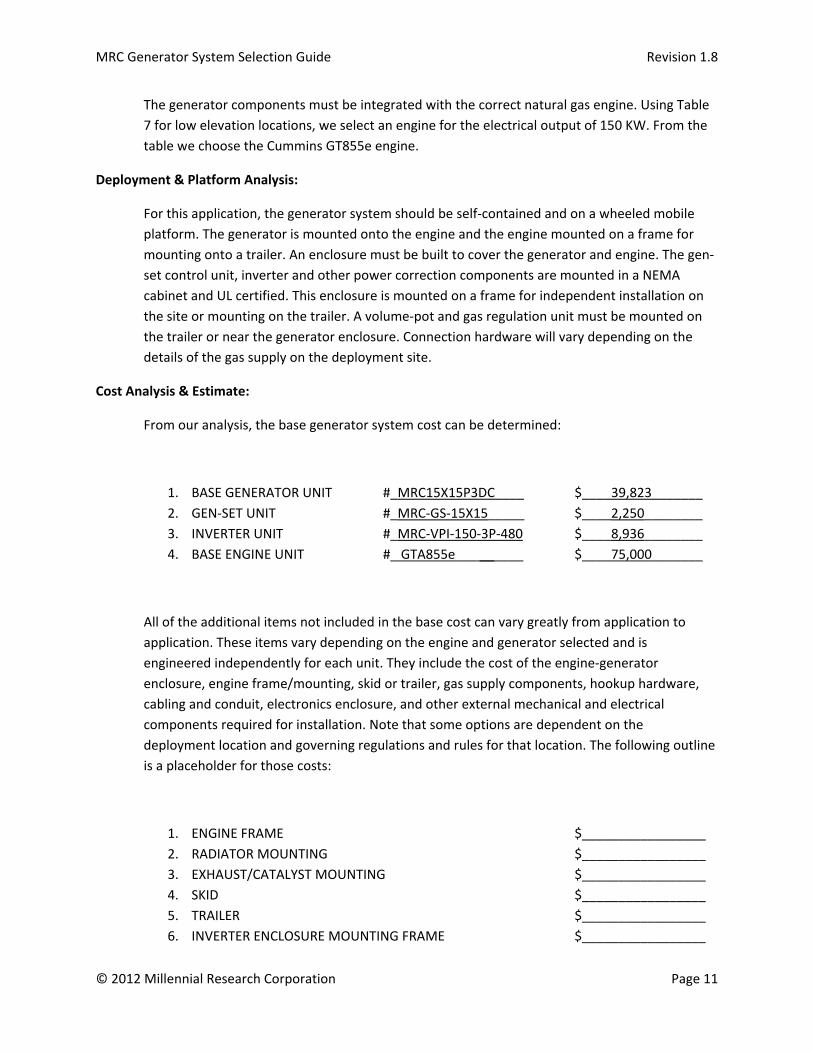
The generator components must be integrated with the correct natural gas engine. Using Table
7 for low elevation locations, we select an engine for the electrical output of 150 KW. From the
table we choose the Cummins GT855e engine.
Deployment & Platform Analysis:
For this application, the generator system should be self‐contained and on a wheeled mobile
platform. The generator is mounted onto the engine and the engine mounted on a frame for
mounting onto a trailer. An enclosure must be built to cover the generator and engine. The gen‐
set control unit, inverter and other power correction components are mounted in a NEMA
cabinet and UL certified. This enclosure is mounted on a frame for independent installation on
the site or mounting on the trailer. A volume‐pot and gas regulation unit must be mounted on
the trailer or near the generator enclosure. Connection hardware will vary depending on the
details of the gas supply on the deployment site.
Cost Analysis & Estimate:
From our analysis, the base generator system cost can be determined:
1. BASE GENERATOR UNIT #_MRC15X15P3DC____ $____39,823_______
2. GEN‐SET UNIT #_MRC‐GS‐15X15_____ $____2,250________
3. INVERTER UNIT #_MRC‐VPI‐150‐3P‐480 $____8,936________
4. BASE ENGINE UNIT #_ GTA855e __ ______ $____75,000_______
All of the additional items not included in the base cost can vary greatly from application to
application. These items vary depending on the engine and generator selected and is
engineered independently for each unit. They include the cost of the engine‐generator
enclosure, engine frame/mounting, skid or trailer, gas supply components, hookup hardware,
cabling and conduit, electronics enclosure, and other external mechanical and electrical
components required for installation. Note that some options are dependent on the
deployment location and governing regulations and rules for that location. The following outline
is a placeholder for those costs:
1. ENGINE FRAME $_________________
2. RADIATOR MOUNTING $_________________
3. EXHAUST/CATALYST MOUNTING $_________________
4. SKID $_________________
5. TRAILER $_________________
6. INVERTER ENCLOSURE MOUNTING FRAME $_________________
MRC Generator System Selection Guide Revision 1.8
© 2012 Millennial Research Corporation Page 12
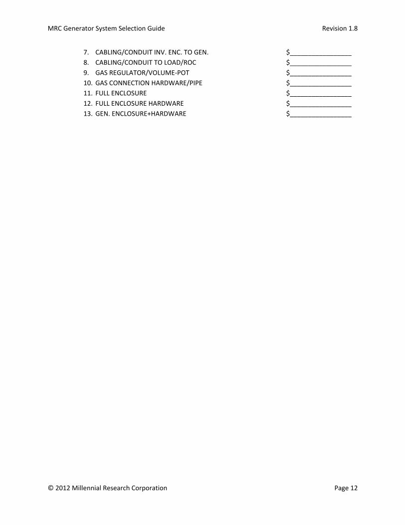
7. CABLING/CONDUIT INV. ENC. TO GEN. $_________________
8. CABLING/CONDUIT TO LOAD/ROC $_________________
9. GAS REGULATOR/VOLUME‐POT $_________________
10. GAS CONNECTION HARDWARE/PIPE $_________________
11. FULL ENCLOSURE $_________________
12. FULL ENCLOSURE HARDWARE $_________________
13. GEN. ENCLOSURE+HARDWARE $_________________

MRC Generator System Selection Guide Revision 1.8
© 2012 Millennial Research Corporation Page 13
AppendixB
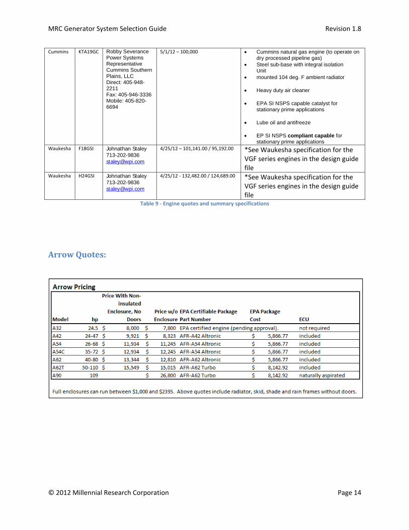
The following table (Table 9) contains details about latest quotes and summary specifications for the
engines recommended in this guide.
Engine Make
Engine Model
Vendor Contact
Last Quote(s) Description of included features
Arrow A Series, VR Series
Doug Waggoner 918‐346‐3750
5/1/12 *See email quote below
*See Arrow product description in the design guide file
Cummins G855 Robby Severance Power Systems Representative Cummins Southern Plains, LLC Direct: 405-948-2211 Fax: 405-946-3336 Mobile: 405-820-6694
5/1/12 – 61,000 Cummins natural gas engine (to operate on dry processed pipeline gas)
Steel sub-base with integral isolation Unit
mounted 104 deg. F ambient radiator
Heavy duty air cleaner
EPA SI NSPS capable catalyst for stationary prime applications
Lube oil and antifreeze
EP SI NSPS compliant capable for stationary prime applications
Cummins GT855e Robby Severance Power Systems Representative Cummins Southern Plains, LLC Direct: 405-948-2211 Fax: 405-946-3336 Mobile: 405-820-6694
5/1/12 – 75,000 Cummins natural gas engine (to operate on dry processed pipeline gas)
Steel sub-base with integral isolation Unit
mounted 104 deg. F ambient radiator
Heavy duty air cleaner
EPA SI NSPS capable catalyst for stationary prime applications
Lube oil and antifreeze
EP SI NSPS certified for stationary prime applications
MRC Generator System Selection Guide Revision 1.8
© 2012 Millennial Research Corporation Page 14
Cummins KTA19GC Robby Severance Power Systems Representative Cummins Southern Plains, LLC Direct: 405-948-2211 Fax: 405-946-3336 Mobile: 405-820-6694
5/1/12 – 100,000 Cummins natural gas engine (to operate on dry processed pipeline gas)
Steel sub-base with integral isolation Unit
mounted 104 deg. F ambient radiator
Heavy duty air cleaner
EPA SI NSPS capable catalyst for stationary prime applications
Lube oil and antifreeze
EP SI NSPS compliant capable for stationary prime applications
Waukesha F18GSI
Johnathan Staley 713-202-9836 [email protected]
4/25/12 – 101,141.00 / 95,192.00 *See Waukesha specification for the VGF series engines in the design guide file
Waukesha H24GSI Johnathan Staley 713-202-9836 [email protected]
4/25/12 ‐ 132,482.00 / 124,689.00 *See Waukesha specification for the VGF series engines in the design guide file
Table 9 ‐ Engine quotes and summary specifications
ArrowQuotes: