Embed Size (px)
Citation preview
www.reinhausen.com
On-load tap-changer OILTAP® R tap selector size E
Operating Instructions

© All rights reserved, Maschinenfabrik Reinhausen
Unauthorized copying and distribution of this document and the utilization and communication of its con-tents are strictly prohibited unless expressly authorized.
Offenders will be held liable for the payment of damages. All rights reserved in the case of registration of a patent, utility model or registered design.
The product may have been modified after this document went to press.
We expressly reserve the right to make changes to the technical data, the design or the scope of delivery.
The information provided and the arrangements agreed during processing of the relevant quotations and orders are strictly binding.
The original operating instructions were drawn up in German.
1 General .......................................................................................... 5
1.1 Safety instructions..................................................................................... 5
1.2 Appropriate use......................................................................................... 6
2 Design/Types................................................................................. 7
3 Shipment ....................................................................................... 9
4 Installation of the on-load tap-changer for cover mounting... 13
4.1 Mounting flange ...................................................................................... 13
4.2 Attaching the on-load tap-changer to the transformer cover................... 14
4.3 Assembly of the diverter switch oil compartment and tap selector ......... 15
5 Installation of the on-load tap-changer into thebell-type tank............................................................................... 21
5.1 Assembly of the diverter switch oil compartment and tap selector, connecting tap selector connecting leads ............................................... 21
5.2 Installation of the on-load tap-changer on the supporting structure........ 21
5.3 Preparation ............................................................................................. 22
5.4 Attaching the bell-type tank..................................................................... 26
6 Connection of the tap winding and on-load tap-changer take-off lead ........................................................... 31
6.1 Connection of the tap selector take-off leads.......................................... 32
6.2 Parallel jumpers for R I 2002-E and R I 3003-E...................................... 34
6.3 Connection of on-load tap-changer take-off lead .................................... 34
7 Transformer ratio test................................................................. 37
8 Drying process and oil filling .................................................... 39
8.1 Drying process ........................................................................................ 39
© Maschinenfabrik Reinhausen 2010 132/02 EN OILTAP® R BR E 3
8.1.1 Vacuum-drying ................................................................................................... 39
8.1.2 Vapor-phase drying ............................................................................................ 40
8.2 Filling with oil .......................................................................................... 42
9 Pipe connections ........................................................................ 43
9.1 Pipe connection R for protective relay RS 2001..................................... 43
9.2 Pipe connection S for suction pipe ......................................................... 44
9.3 Pipe connection Q (special version, only needed with oil filter unit)....... 44
9.4 E2 connection......................................................................................... 44
10 Mounting the motor-drive unit, bevel gear and drive shaft .... 45
10.1 Mounting the motor-drive unit (see appendix, dimension drawing 895660, 893381) .................................................................................... 45
10.2 Mounting the bevel gear ......................................................................... 45
10.3 Mounting the drive shaft (square tube)................................................... 46
11 Commissioning the on-load tap-changer at the transformer manufacturer's site..................................................................... 49
11.1 Tap change operation tests .................................................................... 49
11.2 Complete oil filling .................................................................................. 49
11.3 Ground connections ............................................................................... 51
11.4 Electrical tests on the transformer .......................................................... 51
12 Transportation to the operating site ......................................... 53
13 Commissioning at the operating site........................................ 55
14 Supervision during service, failures......................................... 57
15 Inspections.................................................................................. 59
16 Appendix...................................................................................... 63
4 OILTAP® R BR E 132/02 EN © Maschinenfabrik Reinhausen 2010
1 General
1 General
1.1 Safety instructions
All personnel involved in installation, commissioning, operation, maintenance or repair of the equipment must:
• be suitably professionally qualified and
• strictly observe these Operating Instructions.
Improper operation or misuse can lead to
• serious or fatal injury
• damage to the equipment and other property of the user
• a reduction in the efficiency of the equipment.
Three kinds of safety notices are used in these operating instructions to high-light important information.
WARNING
indicates potential death or injury. Failure to observe this notice may result in serious injury or death.
ATTENTION
indicates potential damage to the equipment and other property of the user. Potential death or injury can also not be ruled out.
NOTE
indicates important information on a particular topic.
© Maschinenfabrik Reinhausen 2010 132/02 EN OILTAP® R BR E 5
1 General
1.2 Appropriate use
ATTENTION
Use the on-load tap-changer only with the transformer specified in the order.
Installation, electrical connection and commissioning of the on-load tap-changer must be carried out exclusively by trained, suitably qualified personnel and under strict observation of these operating instructions.
The operator must ensure that the on-load tap-changer is used as intended.
For safety reasons, any unauthorized work such as installation, alteration, electrical connection, commissioning or modification to the on-load tap-changer equipment is forbidden without first consulting MR!
The trouble-free operation of the drive, the on-load tap-changer and the transformer may be endangered.
ATTENTION
All relevant fire protection regulations must be strictly observed.
6 OILTAP® R BR E 132/02 EN © Maschinenfabrik Reinhausen 2010
2 Design/Types
2 Design/Types
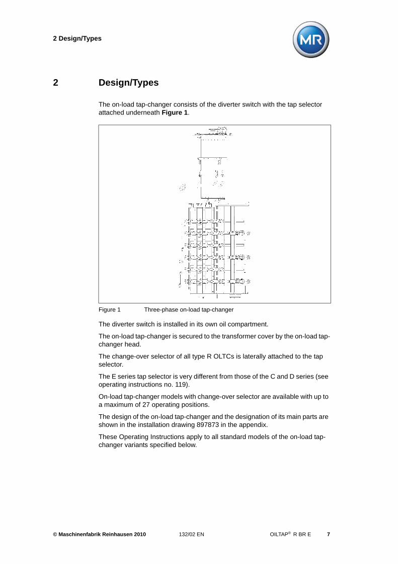
The on-load tap-changer consists of the diverter switch with the tap selector attached underneath Figure 1.
The diverter switch is installed in its own oil compartment.
The on-load tap-changer is secured to the transformer cover by the on-load tap-changer head.
The change-over selector of all type R OLTCs is laterally attached to the tap selector.
The E series tap selector is very different from those of the C and D series (see operating instructions no. 119).
On-load tap-changer models with change-over selector are available with up to a maximum of 27 operating positions.
The design of the on-load tap-changer and the designation of its main parts are shown in the installation drawing 897873 in the appendix.
These Operating Instructions apply to all standard models of the on-load tap-changer variants specified below.
Figure 1 Three-phase on-load tap-changer
© Maschinenfabrik Reinhausen 2010 132/02 EN OILTAP® R BR E 7

2 Design/Types
Three-phase on-load tap-changer:
R III 1200-E (Figure 1)
Single-phase on-load tap-changer:
R I 1201-E, R I 2002/2402-E, R I 3003-E
Single-phase on-load tap-changers are also available as sets of on-load tap-changers3 x R I 1201-E, 3 x R I 2002/2402-E or 3 x R I 3003-Ewith a shared motor-drive unit.
8 OILTAP® R BR E 132/02 EN © Maschinenfabrik Reinhausen 2010
3 Shipment
3 Shipment
On-load tap-changer and motor-drive unit are shipped in the adjustment posi-tion. The on-load tap-changer is packed in two parts – diverter switch and tap selector – and is well protected against moisture. Both parts are locked in the adjustment position.
The on-load tap-changer equipment is shipped as follows:
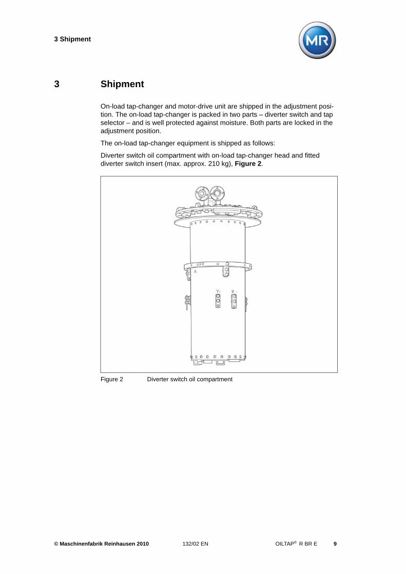
Diverter switch oil compartment with on-load tap-changer head and fitted diverter switch insert (max. approx. 210 kg), Figure 2.
Figure 2 Diverter switch oil compartment
© Maschinenfabrik Reinhausen 2010 132/02 EN OILTAP® R BR E 9
3 Shipment
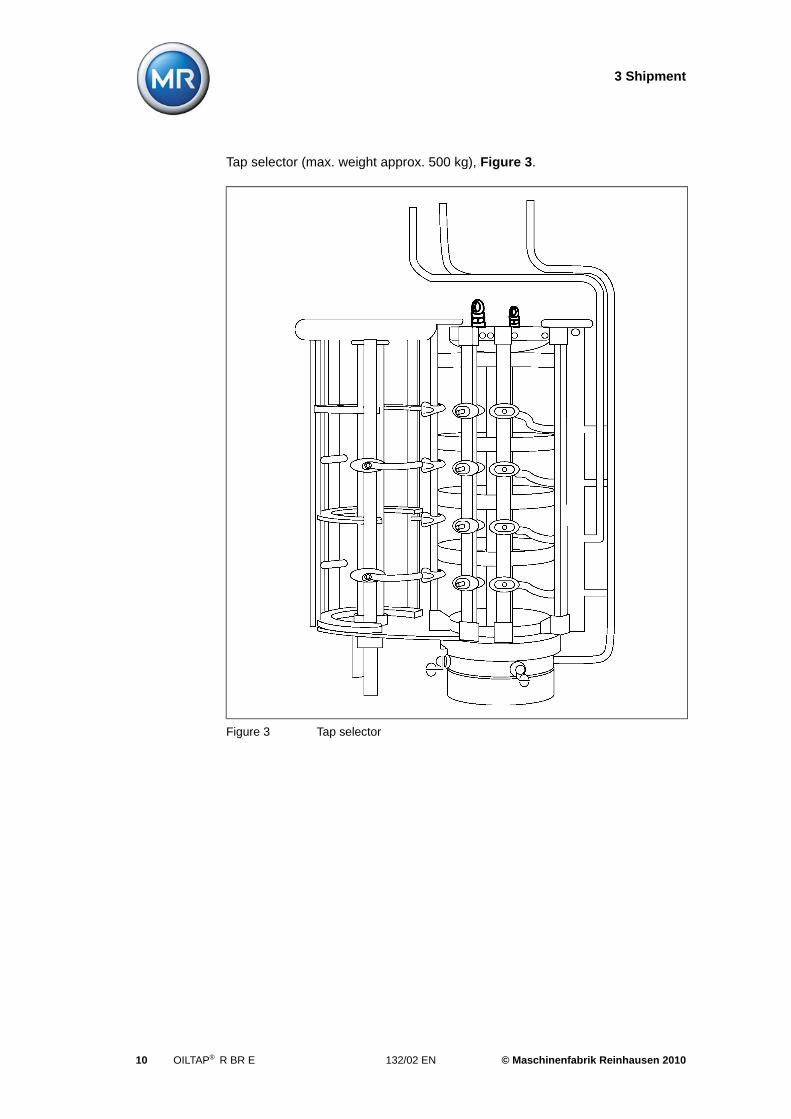
Tap selector (max. weight approx. 500 kg), Figure 3.
Figure 3 Tap selector
10 OILTAP® R BR E 132/02 EN © Maschinenfabrik Reinhausen 2010
3 Shipment
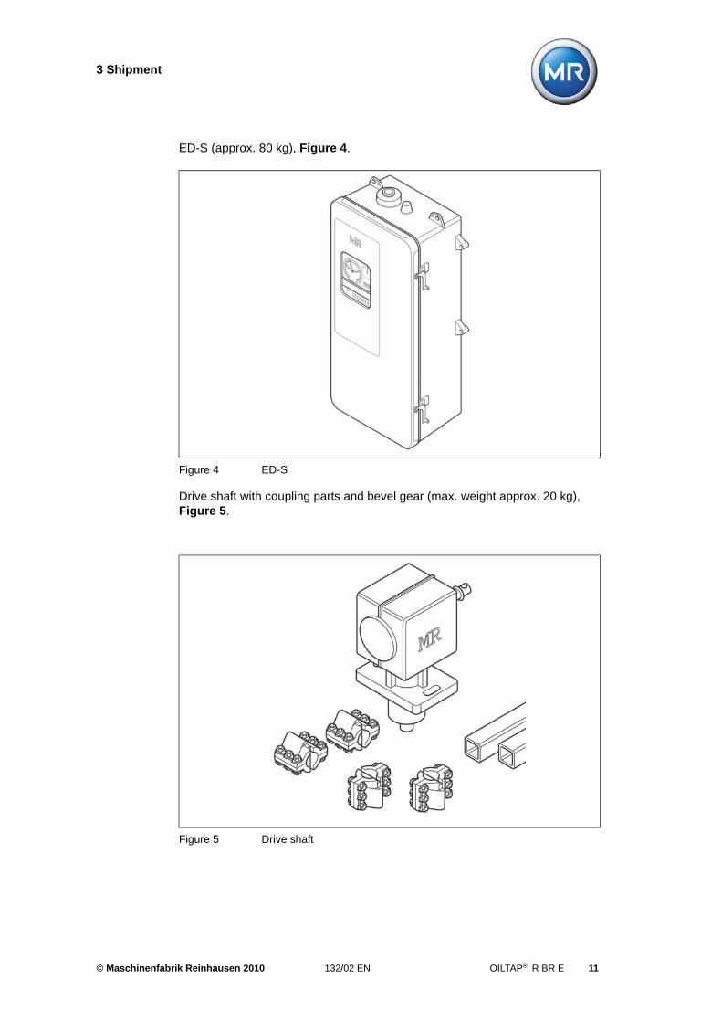
ED-S (approx. 80 kg), Figure 4.
Drive shaft with coupling parts and bevel gear (max. weight approx. 20 kg), Figure 5.
Figure 4 ED-S
Figure 5 Drive shaft
© Maschinenfabrik Reinhausen 2010 132/02 EN OILTAP® R BR E 11
3 Shipment
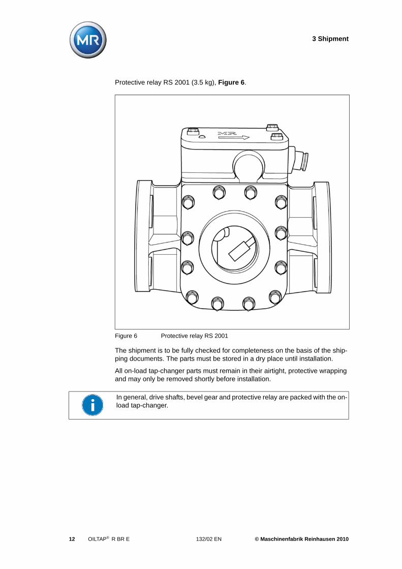
Protective relay RS 2001 (3.5 kg), Figure 6.
The shipment is to be fully checked for completeness on the basis of the ship-ping documents. The parts must be stored in a dry place until installation.
All on-load tap-changer parts must remain in their airtight, protective wrapping and may only be removed shortly before installation.
Figure 6 Protective relay RS 2001
In general, drive shafts, bevel gear and protective relay are packed with the on-load tap-changer.
12 OILTAP® R BR E 132/02 EN © Maschinenfabrik Reinhausen 2010
4 Installation of the on-load tap-changer for cover mounting
4 Installation of the on-load tap-changer for cover mounting
4.1 Mounting flange
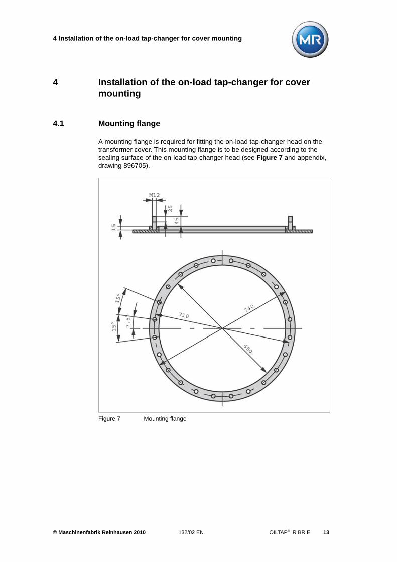
A mounting flange is required for fitting the on-load tap-changer head on the transformer cover. This mounting flange is to be designed according to the sealing surface of the on-load tap-changer head (see Figure 7 and appendix, drawing 896705).
Figure 7 Mounting flange
© Maschinenfabrik Reinhausen 2010 132/02 EN OILTAP® R BR E 13
4 Installation of the on-load tap-changer for cover mounting
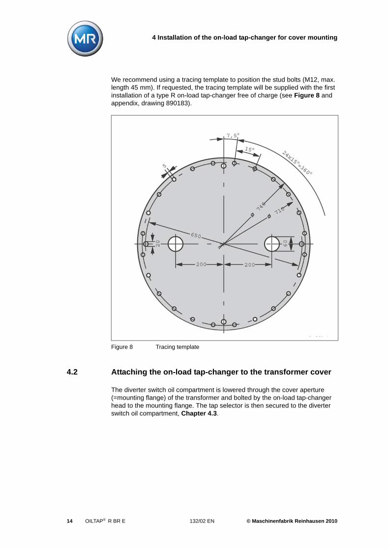
We recommend using a tracing template to position the stud bolts (M12, max. length 45 mm). If requested, the tracing template will be supplied with the first installation of a type R on-load tap-changer free of charge (see Figure 8 and appendix, drawing 890183).
4.2 Attaching the on-load tap-changer to the transformer cover
The diverter switch oil compartment is lowered through the cover aperture (=mounting flange) of the transformer and bolted by the on-load tap-changer head to the mounting flange. The tap selector is then secured to the diverter switch oil compartment, Chapter 4.3.
Figure 8 Tracing template
14 OILTAP® R BR E 132/02 EN © Maschinenfabrik Reinhausen 2010
4 Installation of the on-load tap-changer for cover mounting
Proceed as follows:
1. Place the diverter switch oil compartment on a level surface.
2. Clean sealing faces on mounting flange and on-load tap-changer head.
3. Place an oil-resistant gasket on the mounting flange.
4. Lift the diverter switch oil compartment by hooking up the on-load tap-changer head and carefully lower the oil compartment into the opening of the mounting flange.
Pay attention to the screening rings (with Um > 170 kV only).
5. Check the mounting position of the on-load tap-changer head.
6. Fasten the on-load tap-changer head to the mounting flange.
4.3 Assembly of the diverter switch oil compartment and tap selector
The tap selector is raised from below to the diverter switch oil compartment and connected to it. Thus the mechanical coupling for the tap selector drive is estab-lished. Finally, connect the tap selector connecting leads to the diverter switch oil compartment.
ATTENTION
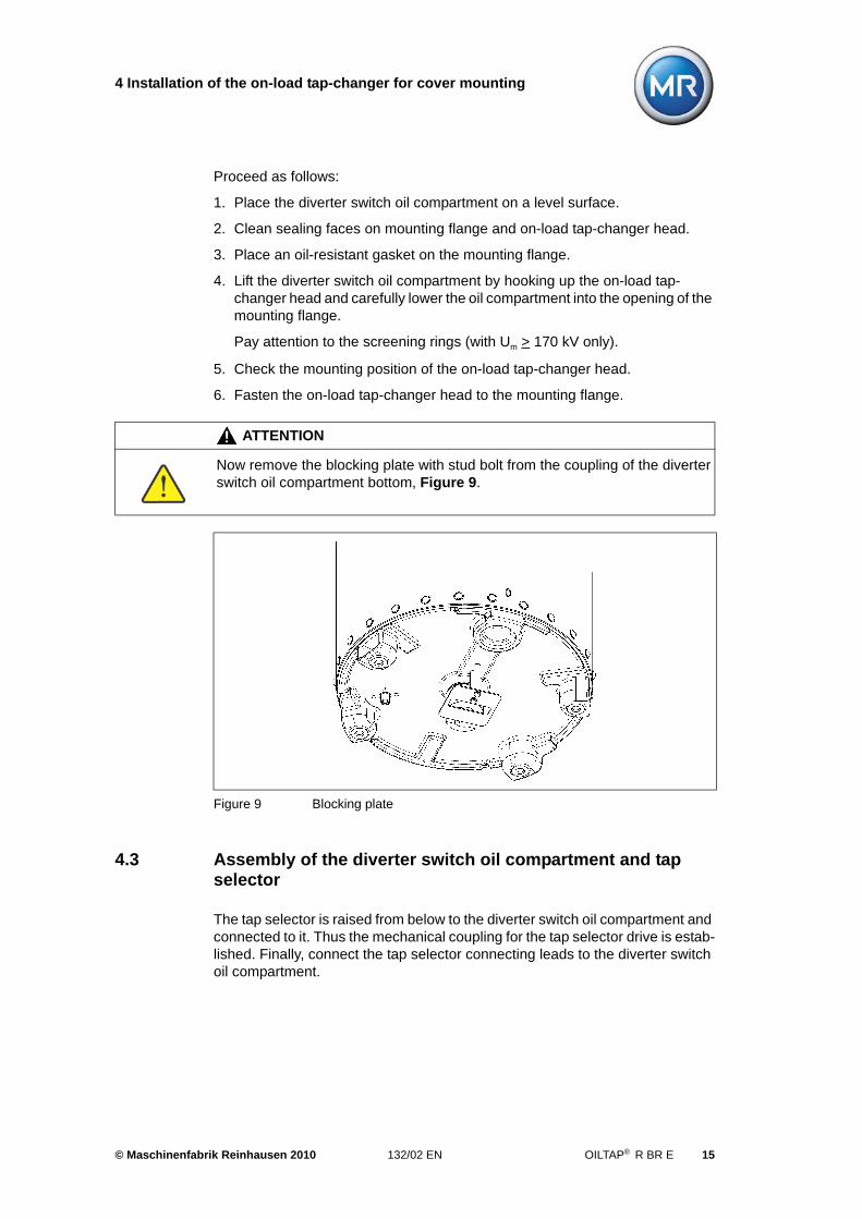
Now remove the blocking plate with stud bolt from the coupling of the diverter switch oil compartment bottom, Figure 9.
Figure 9 Blocking plate
© Maschinenfabrik Reinhausen 2010 132/02 EN OILTAP® R BR E 15
4 Installation of the on-load tap-changer for cover mounting
Proceed as follows:
1. Put the tap selector down on a level surface. Get ready 4 lock nuts M12 with washers.
2. Place the tap selector on the lifting device.
3. Lift tap selector under diverter switch oil compartment. Take care that the tap selector connecting leads clear the diverter switch oil compartment and remain undamaged.
4. Match the position of the two coupling parts and the attachment points of tap selector suspension and oil compartment base.
5. Raise the tap selector to its final height.
6. Bolt the tap selector suspension to the oil compartment base:
ATTENTION
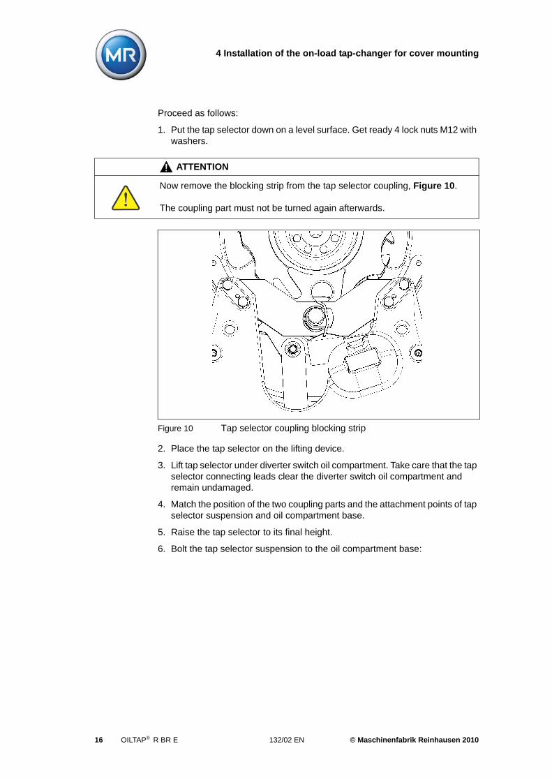
Now remove the blocking strip from the tap selector coupling, Figure 10.
The coupling part must not be turned again afterwards.
Figure 10 Tap selector coupling blocking strip
16 OILTAP® R BR E 132/02 EN © Maschinenfabrik Reinhausen 2010
4 Installation of the on-load tap-changer for cover mounting
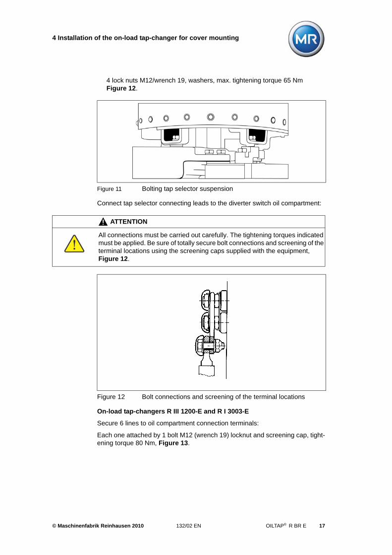
4 lock nuts M12/wrench 19, washers, max. tightening torque 65 Nm Figure 12.
Connect tap selector connecting leads to the diverter switch oil compartment:
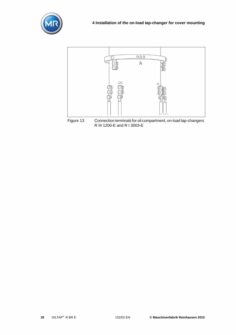
On-load tap-changers R III 1200-E and R I 3003-E
Secure 6 lines to oil compartment connection terminals:
Each one attached by 1 bolt M12 (wrench 19) locknut and screening cap, tight-ening torque 80 Nm, Figure 13.
Figure 11 Bolting tap selector suspension
ATTENTION
All connections must be carried out carefully. The tightening torques indicated must be applied. Be sure of totally secure bolt connections and screening of the terminal locations using the screening caps supplied with the equipment, Figure 12.
Figure 12 Bolt connections and screening of the terminal locations
© Maschinenfabrik Reinhausen 2010 132/02 EN OILTAP® R BR E 17
4 Installation of the on-load tap-changer for cover mounting
Figure 13 Connection terminals for oil compartment, on-load tap-changers R III 1200-E and R I 3003-E
18 OILTAP® R BR E 132/02 EN © Maschinenfabrik Reinhausen 2010
4 Installation of the on-load tap-changer for cover mounting
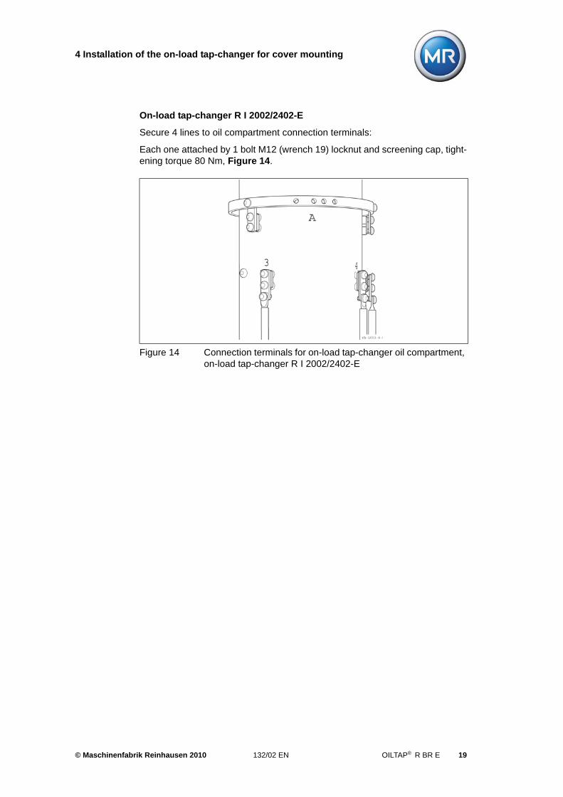
On-load tap-changer R I 2002/2402-E
Secure 4 lines to oil compartment connection terminals:
Each one attached by 1 bolt M12 (wrench 19) locknut and screening cap, tight-ening torque 80 Nm, Figure 14.
Figure 14 Connection terminals for on-load tap-changer oil compartment, on-load tap-changer R I 2002/2402-E
© Maschinenfabrik Reinhausen 2010 132/02 EN OILTAP® R BR E 19

5 Installation of the on-load tap-changer into the bell-type tank
5 Installation of the on-load tap-changer into thebell-type tank
To install the on-load tap-changer into a transformer with a bell-type tank the on-load tap-changer has to be mounted onto a supporting structure. For this pur-pose, the on-load tap-changer is equipped with a supporting flange at the diverter switch oil compartment (special design, see appendix, drawing 896762).
First lift the on-load tap-changer into the supporting structure and connect it to the tap winding. The on-load tap-changer must be attached to the supporting structure in such a way that it cannot be displaced. The supporting flange has drilled holes so that it can easily be affixed to the supporting structure. We recommend placing temporary spacers between the supporting structure and supporting flange and removing them before the bell-type tank is mounted.
After mounting the bell-type tank raise the on-load tap-changer (diverter switch insert removed) by means of the lifting traverse (see appendix, drawing 890 180) and attach both the on-load tap-changer and the on-load tap-changer head to the bell-type tank. To attach the on-load tap-changer head to the bell-type tank we recommend the use of a mounting flange as described in Chapter 4.1.
5.1 Assembly of the diverter switch oil compartment and tap selector, connecting tap selector connecting leads
The diverter switch oil compartment and tap selector should be assembled and the connecting tap selector connecting leads connected in accordance with Chapter 4.3.
5.2 Installation of the on-load tap-changer on the supporting structure
Lift the assembled on-load tap-changer (according to Chapter 4.1) into the sup-porting structure. Check the mounting position of the on-load tap-changer and fix it securely.
NOTE
The on-load tap-changer must be suspended fully vertically in the supporting structure. The on-load tap-changer must be mounted so that it need not be lifted by more than 5 to 20 mm to reach its final position after the bell-type tank is set up.
© Maschinenfabrik Reinhausen 2010 132/02 EN OILTAP® R BR E 21
5 Installation of the on-load tap-changer into the bell-type tank
It is of advantage to install spacer blocks between supporting structure and supporting flange of the on-load tap-changer in such a way that the on-load tap-changer is in its envisaged final position after the bell-type tank is set up. By this measure the leads to be connected to the on-load tap-changer can be correctly dimensioned in length. Remove the spacer blocks after the connection of the leads.
Connect the tap winding and the on-load tap-changer take-off leads according to Chapter 6.
The drying process and transformer ratio test are to be performed in accor-dance with Chapter 7 and 8.
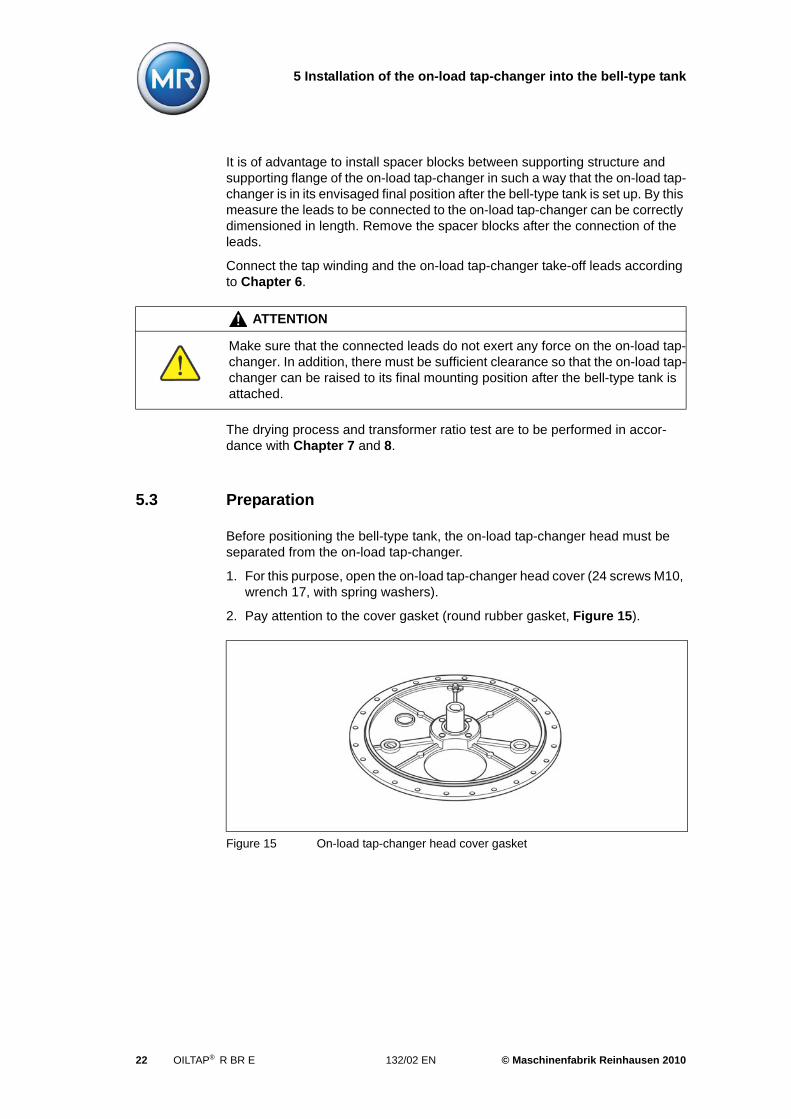
5.3 Preparation
Before positioning the bell-type tank, the on-load tap-changer head must be separated from the on-load tap-changer.
1. For this purpose, open the on-load tap-changer head cover (24 screws M10, wrench 17, with spring washers).
2. Pay attention to the cover gasket (round rubber gasket, Figure 15).
ATTENTION
Make sure that the connected leads do not exert any force on the on-load tap-changer. In addition, there must be sufficient clearance so that the on-load tap-changer can be raised to its final mounting position after the bell-type tank is attached.
Figure 15 On-load tap-changer head cover gasket
22 OILTAP® R BR E 132/02 EN © Maschinenfabrik Reinhausen 2010
5 Installation of the on-load tap-changer into the bell-type tank
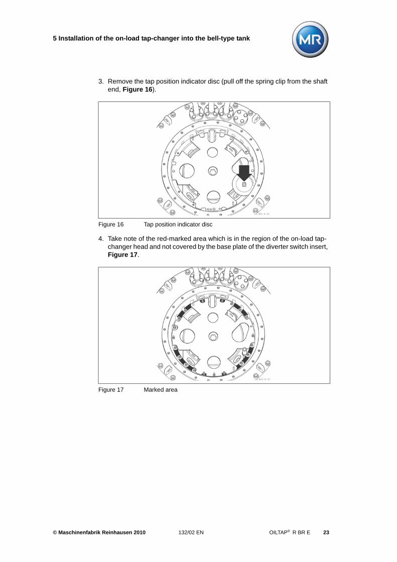
3. Remove the tap position indicator disc (pull off the spring clip from the shaft end, Figure 16).
4. Take note of the red-marked area which is in the region of the on-load tap-changer head and not covered by the base plate of the diverter switch insert, Figure 17.
Figure 16 Tap position indicator disc
Figure 17 Marked area
© Maschinenfabrik Reinhausen 2010 132/02 EN OILTAP® R BR E 23
5 Installation of the on-load tap-changer into the bell-type tank
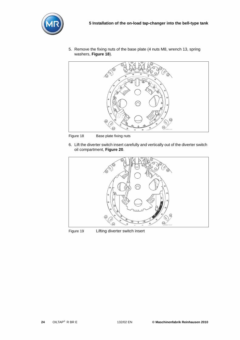
5. Remove the fixing nuts of the base plate (4 nuts M8, wrench 13, spring washers, Figure 18).
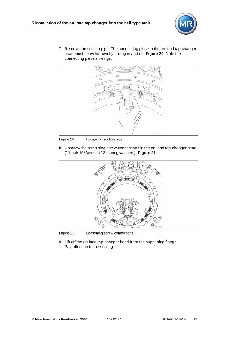
6. Lift the diverter switch insert carefully and vertically out of the diverter switch oil compartment, Figure 20.
Figure 18 Base plate fixing nuts
Figure 19 Lifting diverter switch insert
24 OILTAP® R BR E 132/02 EN © Maschinenfabrik Reinhausen 2010
5 Installation of the on-load tap-changer into the bell-type tank
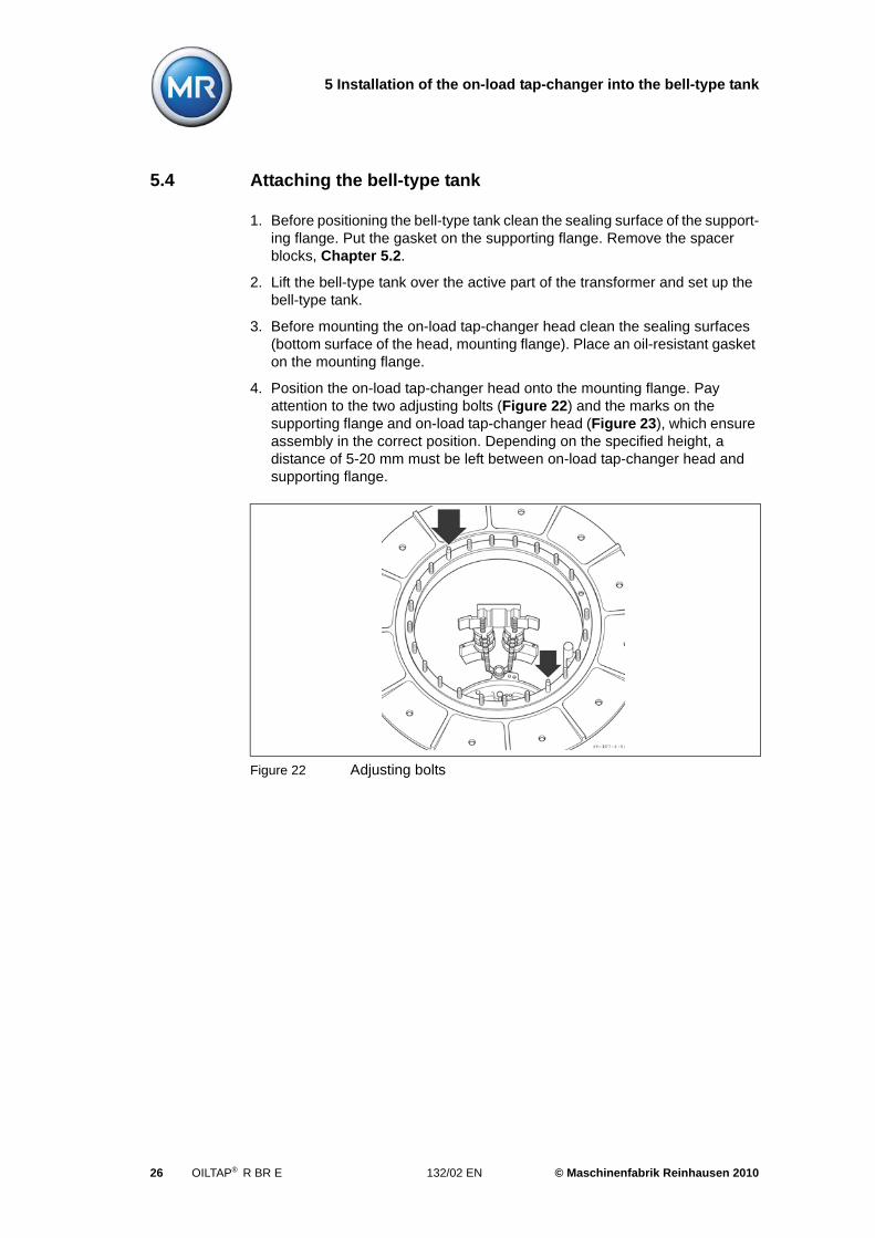
7. Remove the suction pipe. The connecting piece in the on-load tap-changer head must be withdrawn by pulling in and off, Figure 20. Note the connecting piece's o-rings.
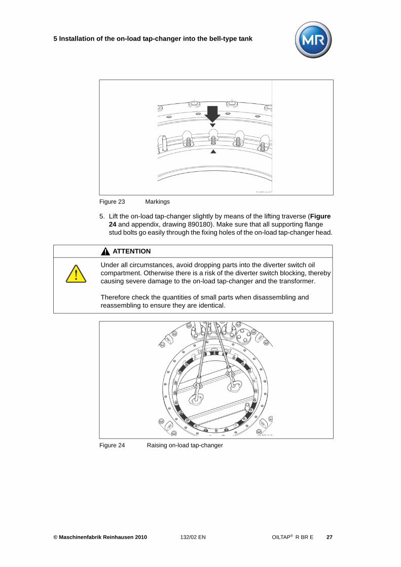
8. Unscrew the remaining screw connections in the on-load tap-changer head (17 nuts M8/wrench 13, spring washers), Figure 21.
9. Lift off the on-load tap-changer head from the supporting flange. Pay attention to the sealing.
Figure 20 Removing suction pipe
Figure 21 Loosening screw connections
© Maschinenfabrik Reinhausen 2010 132/02 EN OILTAP® R BR E 25
5 Installation of the on-load tap-changer into the bell-type tank
5.4 Attaching the bell-type tank
1. Before positioning the bell-type tank clean the sealing surface of the support-ing flange. Put the gasket on the supporting flange. Remove the spacer blocks, Chapter 5.2.
2. Lift the bell-type tank over the active part of the transformer and set up the bell-type tank.
3. Before mounting the on-load tap-changer head clean the sealing surfaces (bottom surface of the head, mounting flange). Place an oil-resistant gasket on the mounting flange.
4. Position the on-load tap-changer head onto the mounting flange. Pay attention to the two adjusting bolts (Figure 22) and the marks on the supporting flange and on-load tap-changer head (Figure 23), which ensure assembly in the correct position. Depending on the specified height, a distance of 5-20 mm must be left between on-load tap-changer head and supporting flange.
Figure 22 Adjusting bolts
26 OILTAP® R BR E 132/02 EN © Maschinenfabrik Reinhausen 2010
5 Installation of the on-load tap-changer into the bell-type tank
5. Lift the on-load tap-changer slightly by means of the lifting traverse (Figure 24 and appendix, drawing 890180). Make sure that all supporting flange stud bolts go easily through the fixing holes of the on-load tap-changer head.
Figure 23 Markings
ATTENTION
Under all circumstances, avoid dropping parts into the diverter switch oil compartment. Otherwise there is a risk of the diverter switch blocking, thereby causing severe damage to the on-load tap-changer and the transformer.
Therefore check the quantities of small parts when disassembling and reassembling to ensure they are identical.
Figure 24 Raising on-load tap-changer
© Maschinenfabrik Reinhausen 2010 132/02 EN OILTAP® R BR E 27
5 Installation of the on-load tap-changer into the bell-type tank
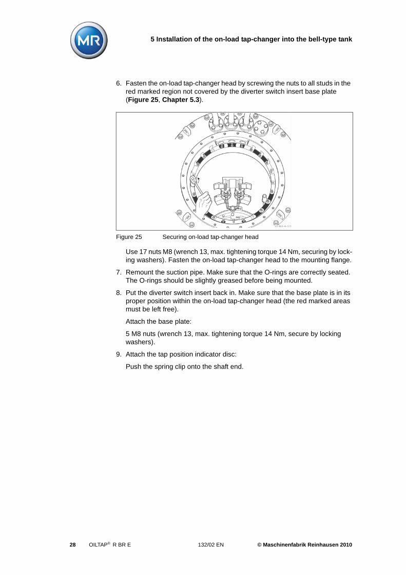
6. Fasten the on-load tap-changer head by screwing the nuts to all studs in the red marked region not covered by the diverter switch insert base plate (Figure 25, Chapter 5.3).
Use 17 nuts M8 (wrench 13, max. tightening torque 14 Nm, securing by lock-ing washers). Fasten the on-load tap-changer head to the mounting flange.
7. Remount the suction pipe. Make sure that the O-rings are correctly seated. The O-rings should be slightly greased before being mounted.
8. Put the diverter switch insert back in. Make sure that the base plate is in its proper position within the on-load tap-changer head (the red marked areas must be left free).
Attach the base plate:
5 M8 nuts (wrench 13, max. tightening torque 14 Nm, secure by locking washers).
9. Attach the tap position indicator disc:
Push the spring clip onto the shaft end.
Figure 25 Securing on-load tap-changer head
28 OILTAP® R BR E 132/02 EN © Maschinenfabrik Reinhausen 2010
5 Installation of the on-load tap-changer into the bell-type tank
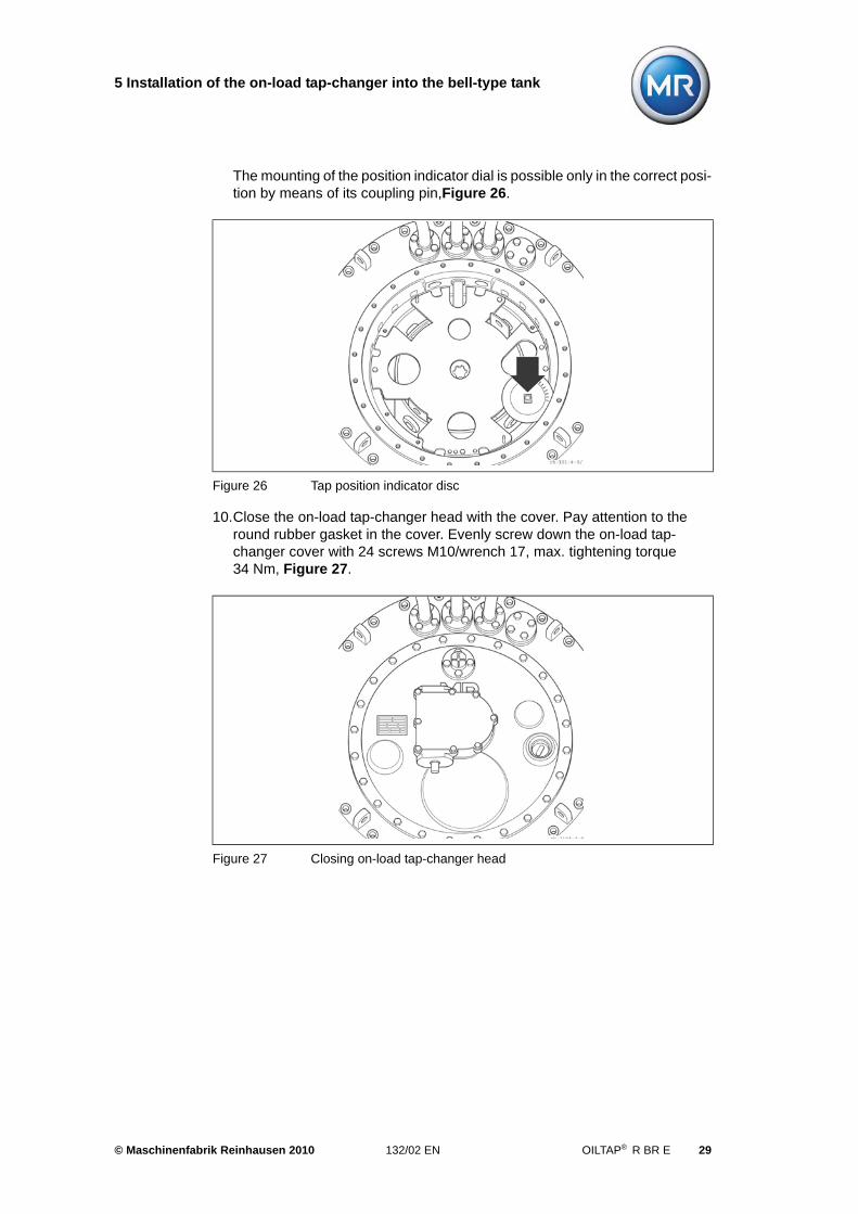
The mounting of the position indicator dial is possible only in the correct posi-tion by means of its coupling pin,Figure 26.
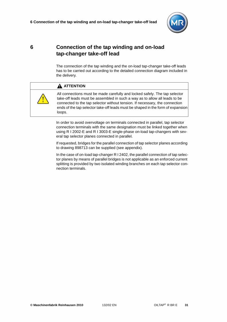
10.Close the on-load tap-changer head with the cover. Pay attention to the round rubber gasket in the cover. Evenly screw down the on-load tap-changer cover with 24 screws M10/wrench 17, max. tightening torque 34 Nm, Figure 27.
Figure 26 Tap position indicator disc
Figure 27 Closing on-load tap-changer head
© Maschinenfabrik Reinhausen 2010 132/02 EN OILTAP® R BR E 29

6 Connection of the tap winding and on-load tap-changer take-off lead
6 Connection of the tap winding and on-load tap-changer take-off lead
The connection of the tap winding and the on-load tap-changer take-off leads has to be carried out according to the detailed connection diagram included in the delivery.
In order to avoid overvoltage on terminals connected in parallel, tap selector connection terminals with the same designation must be linked together when using R I 2002-E and R I 3003-E single-phase on-load tap-changers with sev-eral tap selector planes connected in parallel.
If requested, bridges for the parallel connection of tap selector planes according to drawing 898713 can be supplied (see appendix).
In the case of on-load tap-changer R I 2402, the parallel connection of tap selec-tor planes by means of parallel bridges is not applicable as an enforced current splitting is provided by two isolated winding branches on each tap selector con-nection terminals.
ATTENTION
All connections must be made carefully and locked safely. The tap selector take-off leads must be assembled in such a way as to allow all leads to be connected to the tap selector without tension. If necessary, the connection ends of the tap selector take-off leads must be shaped in the form of expansion loops.
© Maschinenfabrik Reinhausen 2010 132/02 EN OILTAP® R BR E 31
6 Connection of the tap winding and on-load tap-changer take-off lead
6.1 Connection of the tap selector take-off leads
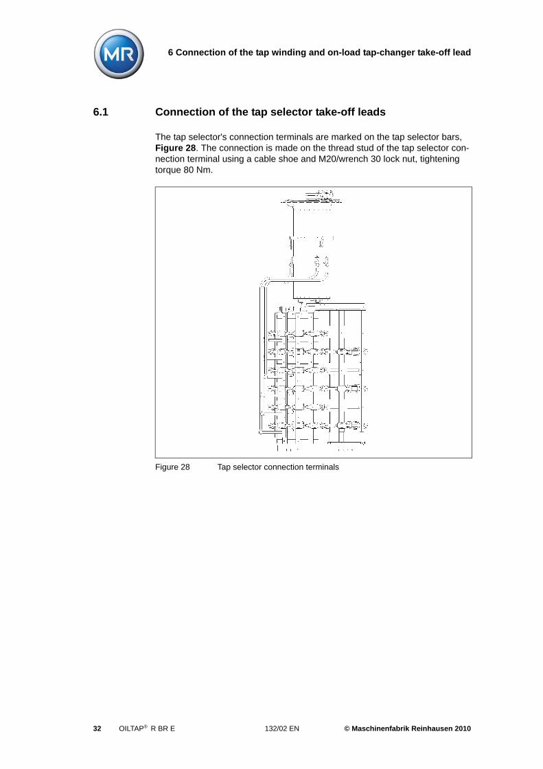
The tap selector's connection terminals are marked on the tap selector bars, Figure 28. The connection is made on the thread stud of the tap selector con-nection terminal using a cable shoe and M20/wrench 30 lock nut, tightening torque 80 Nm.
Figure 28 Tap selector connection terminals
32 OILTAP® R BR E 132/02 EN © Maschinenfabrik Reinhausen 2010
6 Connection of the tap winding and on-load tap-changer take-off lead
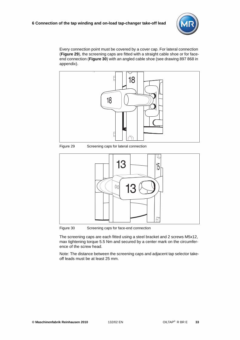
Every connection point must be covered by a cover cap. For lateral connection (Figure 29), the screening caps are fitted with a straight cable shoe or for face-end connection (Figure 30) with an angled cable shoe (see drawing 897 868 in appendix).
The screening caps are each fitted using a steel bracket and 2 screws M5x12, max tightening torque 5.5 Nm and secured by a center mark on the circumfer-ence of the screw head.
Note: The distance between the screening caps and adjacent tap selector take-off leads must be at least 25 mm.
Figure 29 Screening caps for lateral connection
Figure 30 Screening caps for face-end connection
© Maschinenfabrik Reinhausen 2010 132/02 EN OILTAP® R BR E 33
6 Connection of the tap winding and on-load tap-changer take-off lead
6.2 Parallel jumpers for R I 2002-E and R I 3003-E
Bridges for connecting the connection terminals of the tap selector and change-over selector in parallel can be supplied on request.
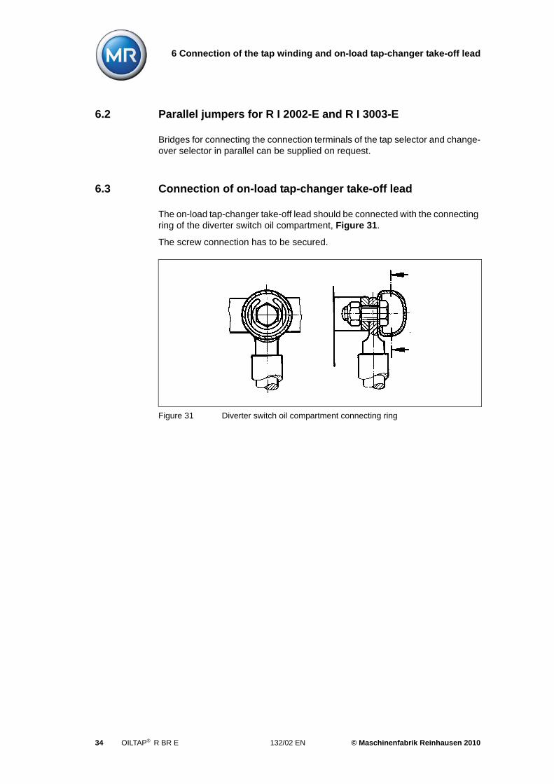
6.3 Connection of on-load tap-changer take-off lead
The on-load tap-changer take-off lead should be connected with the connecting ring of the diverter switch oil compartment, Figure 31.
The screw connection has to be secured.
Figure 31 Diverter switch oil compartment connecting ring
34 OILTAP® R BR E 132/02 EN © Maschinenfabrik Reinhausen 2010
6 Connection of the tap winding and on-load tap-changer take-off lead
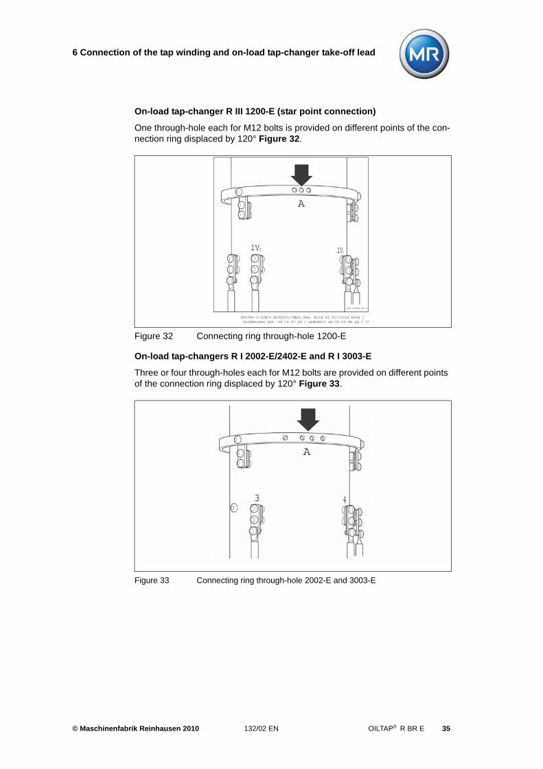
On-load tap-changer R III 1200-E (star point connection)
One through-hole each for M12 bolts is provided on different points of the con-nection ring displaced by 120° Figure 32.
On-load tap-changers R I 2002-E/2402-E and R I 3003-E
Three or four through-holes each for M12 bolts are provided on different points of the connection ring displaced by 120° Figure 33.
Figure 32 Connecting ring through-hole 1200-E
Figure 33 Connecting ring through-hole 2002-E and 3003-E
© Maschinenfabrik Reinhausen 2010 132/02 EN OILTAP® R BR E 35

7 Transformer ratio test
7 Transformer ratio test
We recommend performing a transformer ratio test with low alternating voltage before drying the transformer.
To operate the drive shaft of the on-load tap-changer head a short tube of 25 mm nominal width with a screwed-in coupling bolt of 12 mm diameter together with a hand wheel or a hand crank may be used.
If using the 3 x R I 2002-E...3003-E on-load tap-changer set, all 3 on-load tap-changer heads must be connected to one another using the horizontal drive shaft part, Chapter 10.
If using the ED motor-drive unit, 16.5 revolutions are needed per step on the on-load tap-changer drive shaft. Operation of the diverter switch is clearly audible.
When operating the change-over selector a higher torque is required.
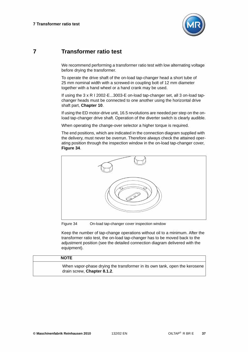
The end positions, which are indicated in the connection diagram supplied with the delivery, must never be overrun. Therefore always check the attained oper-ating position through the inspection window in the on-load tap-changer cover, Figure 34.
Keep the number of tap-change operations without oil to a minimum. After the transformer ratio test, the on-load tap-changer has to be moved back to the adjustment position (see the detailed connection diagram delivered with the equipment).
Figure 34 On-load tap-changer cover inspection window
NOTE
When vapor-phase drying the transformer in its own tank, open the kerosene drain screw, Chapter 8.1.2.
© Maschinenfabrik Reinhausen 2010 132/02 EN OILTAP® R BR E 37

8 Drying process and oil filling
8 Drying process and oil filling
8.1 Drying process
As a precondition of MR's guarantee of the dielectric properties of the on-load tap-changer, a minimum drying treatment must be carried out according to the following instructions (alternatively Chapter 8.1.1 or 8.1.2).
8.1.1 Vacuum-drying
8.1.1.1 Vacuum-drying in the autoclave
• Heating up:
Heat the on-load tap-changer in air at atmospheric pressure, increasing the temperature by approx. 10 °C/h up to a final temperature of not more than 110 °C.
• Pre-drying:
Pre-dry the on-load tap-changer in circulating air at a max. temperature of 110 °C applied to the on-load tap-changer for a duration of 20 hours.
• Drying:
Vacuum drying at a temperature of 110 °C max. applied to the on-load tap-changer and a residual pressure of at most 10-3 bar for a duration of at least 50 hours.
8.1.1.2 Drying in the transformer tank
The on-load tap-changer cover is vacuum-proof.
To ensure sufficient drying of the interior of the oil compartment and the incor-porated diverter switch insert, a short by-pass tube of 25 mm nominal width must be connected between the transformer tank and a pipe connection at the on-load tap-changer head that leads directly into the interior.
NOTE
Before drying the transformer in the autoclave, the on-load tap-changer cover must be removed and stored outside the autoclave.
NOTE
If the transformer is to be dried in its own tank, the interior of the on-load tap-changer must be connected to vacuum by a connecting pipe, as the on-load tap-changer cover remains closed during the entire drying process.
© Maschinenfabrik Reinhausen 2010 132/02 EN OILTAP® R BR E 39
8 Drying process and oil filling
The connection line must be installed on the on-load tap-changer head between the connections E2 and Q or E2 and R (for location of the connections on on-load tap-changer head, see Chapter 9 and appendix, drawing 893 899).
Procedure, temperature, duration and pressure of the drying process are described in Chapter 8.1.1.1.
8.1.2 Vapor-phase drying
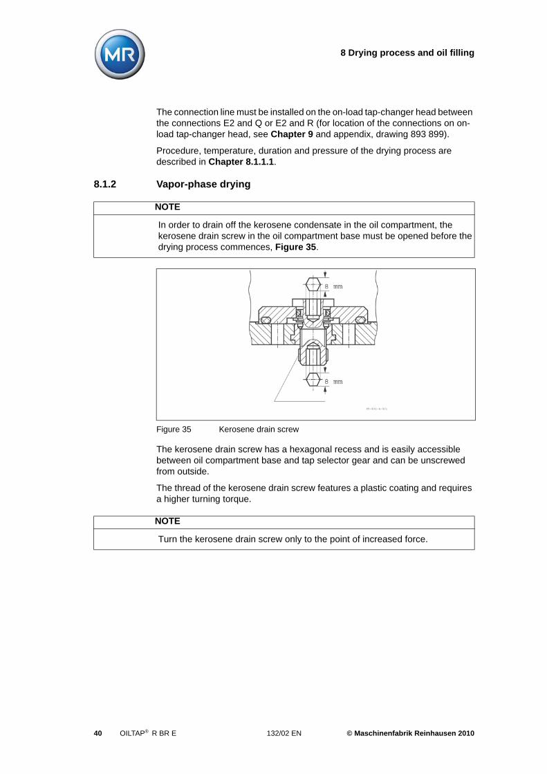
The kerosene drain screw has a hexagonal recess and is easily accessible between oil compartment base and tap selector gear and can be unscrewed from outside.
The thread of the kerosene drain screw features a plastic coating and requires a higher turning torque.
NOTE
In order to drain off the kerosene condensate in the oil compartment, the kerosene drain screw in the oil compartment base must be opened before the drying process commences, Figure 35.
Figure 35 Kerosene drain screw
NOTE
Turn the kerosene drain screw only to the point of increased force.
40 OILTAP® R BR E 132/02 EN © Maschinenfabrik Reinhausen 2010
8 Drying process and oil filling
When vapor-phase drying the transformer in its own tank (see Chapter 8.1.2.2) the kerosene drain screw, in general, is not accessible from outside and can only be opened from the inside. In this case, the diverter switch insert must be removed, the kerosene drain screw screwed on with an extended socket wrench (see appendix, drawing 890 182) and the diverter switch insert refitted.
8.1.2.1 Vapor-phase drying in the vacuum autoclave
• Heating up:
Supply kerosene vapor at a temperature of approx. 90°C. Keep this tempera-ture constant for approx. 3-4 hours.
• Drying:
Increase the kerosene vapor temperature applied to the on- load tap-changer by approx.10 °C/h to the desired final temperature which should not exceed 125 °C. The duration of the drying process depends on the transformer.
8.1.2.2 Vapor-phase drying in the transformer tank
If the transformer is to be dried in its own tank, the on-load tap-changer cover remains closed during the entire drying process.
The on-load tap-changer cover is vacuum-proof. To ensure sufficient drying of the interior of the diverter switch oil compartment and of the diverter switch insert, it is necessary to connect a common tube of at least 50 mm nominal width between the kerosene vapor lead and at least two pipe connections of the on-load tap-changer head leading into the diverter switch compartment.
For this purpose use pipe connections R and Q for on-load tap-changer type R (for position of pipe connections at the on-load tap-changer head see Chapter 9 and appendix, drawing 893 899).
Procedure, temperature and duration of the drying process are described in Chapter 8.1.2.1.
ATTENTION
The kerosene drain screw must be closed again after the drying process to ensure that no oil from the diverter switch oil compartment can flow into the transformer oil tank!
NOTE
Before drying the transformer in the autoclave, the on-load tap-changer cover must be removed and stored outside the autoclave.
© Maschinenfabrik Reinhausen 2010 132/02 EN OILTAP® R BR E 41
8 Drying process and oil filling
8.1.2.3 Operating the on-load tap-changer
The on-load tap-changer must not be operated before the diverter switch oil compartment has been filled with oil and the tap selector has been completely immersed in transformer oil.
8.2 Filling with oil
Close the on-load tap-changer head with the cover. Tighten all 24 cover bolts M10, wrench 17 equally (max. tightening torque 34 Nm).
On-load tap-changer and transformer are simultaneously filled with new trans-former oil under vacuum.
When filling with oil, pipe connection S or R on the on-load tap-changer head is to be used. For evacuating purposes, a by-pass tube between connections E2 and Q is to be installed in order to simultaneously apply vacuum to the trans-former and the oil compartment.
ATTENTION
Do not operate the on-load tap-changer after drying without oil wetting, otherwise bearings and gaskets will be damaged.
ATTENTION
The oil compartment and the associated oil conservator must be filled only with new mineral insulating oil for transformers according to IEC 296. The use of other oil puts at risk the trouble-free operation of on-load tap-changer and transformer.
42 OILTAP® R BR E 132/02 EN © Maschinenfabrik Reinhausen 2010
9 Pipe connections
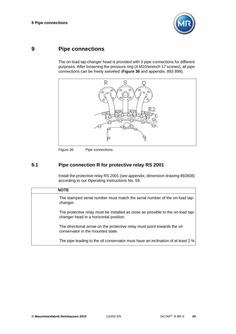
9 Pipe connections
The on-load tap-changer head is provided with 3 pipe connections for different purposes. After loosening the pressure ring (4 M10/wrench 17 screws), all pipe connections can be freely swiveled (Figure 36 and appendix, 893 899).
9.1 Pipe connection R for protective relay RS 2001
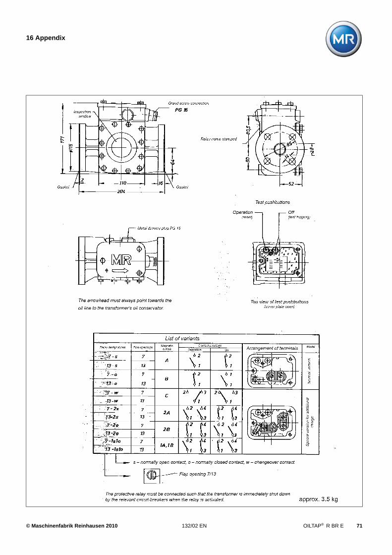
Install the protective relay RS 2001 (see appendix, dimension drawing 892608) according to our Operating Instructions No. 59.
Figure 36 Pipe connections
NOTE
The stamped serial number must match the serial number of the on-load tap-changer.
The protective relay must be installed as close as possible to the on-load tap-changer head in a horizontal position.
The directional arrow on the protective relay must point towards the oil conservator in the mounted state.
The pipe leading to the oil conservator must have an inclination of at least 2 %.
© Maschinenfabrik Reinhausen 2010 132/02 EN OILTAP® R BR E 43
9 Pipe connections
9.2 Pipe connection S for suction pipe
If no feed pipe of a stationary oil filter unit is connected here, a pipe must be connected which ends with a drain valve at the side of the transformer tank at operating height.
9.3 Pipe connection Q (special version, only needed with oil filter unit)
This pipe connection is used to connect the oil return for a stationary oil filter unit. If no oil filter unit is connected, a blank cover is mounted instead of the pipe connection.
9.4 E2 connection
This connection is sealed using a blank cover. It runs into the transformer's oil tank directly under the on-load tap-changer head and can if necessary be con-nected to a collecting pipe for the Buchholz relay.
44 OILTAP® R BR E 132/02 EN © Maschinenfabrik Reinhausen 2010
10 Mounting the motor-drive unit, bevel gear and drive shaft
10 Mounting the motor-drive unit, bevel gear and drive shaft
10.1 Mounting the motor-drive unit (see appendix, dimension drawing 895660, 893381)
Detailed installation instructions can be found in our Operating Instructions no. 138 for the ED motor-drive unit.
10.2 Mounting the bevel gear
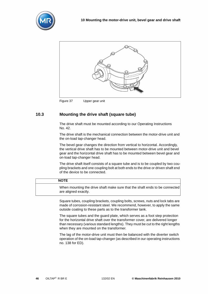
The bevel gear is to be attached to a support on the transformer cover by 2 bolts (through-holes 18 mm diameter, see appendix, drawing 892916).
NOTE
The serial number of the motor-drive unit must match the serial number of the on-load tap-changer (nameplate).
Motor-drive unit and on-load tap-changer must be in the same operating position.
The adjustment position is indicated in the connection of the on-load tap-changer included in delivery.
The motor-drive unit must be mounted at the intended position on the transformer tank in a vertical position and protected against transformer vibrations.
NOTE
The stamped serial number must match the serial number of the on-load tap-changer.
The horizontal drive shaft must align with the shaft end of the on-load tap-changer head.
After loosening the pressure ring (6 bolts M8, wrench 13) the upper gear unit can be freely swiveled, Figure 37. When having adjusted the upper gear unit, tighten the pressure ring (max. tightening torque 15 Nm). The bolts should be secured.
The above notes also apply analogously to the special models of bevel gears and to the intermediate bearings of the vertical or horizontal drive shaft.
© Maschinenfabrik Reinhausen 2010 132/02 EN OILTAP® R BR E 45
10 Mounting the motor-drive unit, bevel gear and drive shaft
10.3 Mounting the drive shaft (square tube)
The drive shaft must be mounted according to our Operating Instructions No. 42.
The drive shaft is the mechanical connection between the motor-drive unit and the on-load tap-changer head.
The bevel gear changes the direction from vertical to horizontal. Accordingly, the vertical drive shaft has to be mounted between motor-drive unit and bevel gear and the horizontal drive shaft has to be mounted between bevel gear and on-load tap-changer head.
The drive shaft itself consists of a square tube and is to be coupled by two cou-pling brackets and one coupling bolt at both ends to the drive or driven shaft end of the device to be connected.
Square tubes, coupling brackets, coupling bolts, screws, nuts and lock tabs are made of corrosion-resistant steel. We recommend, however, to apply the same outside coating to these parts as to the transformer tank.
The square tubes and the guard plate, which serves as a foot step protection for the horizontal drive shaft over the transformer cover, are delivered longer than necessary (various standard lengths). They must be cut to the right lengths when they are mounted on the transformer.
The lag of the motor-drive unit must then be balanced with the diverter switch operation of the on-load tap-changer (as described in our operating instructions no. 138 for ED).
Figure 37 Upper gear unit
NOTE
When mounting the drive shaft make sure that the shaft ends to be connected are aligned exactly.
46 OILTAP® R BR E 132/02 EN © Maschinenfabrik Reinhausen 2010
10 Mounting the motor-drive unit, bevel gear and drive shaft
On-load tap-changer 3 x R I 2002-E...3003-E
The following procedure is recommended for the R III1200 on-load tap-changer.
Due to the special arrangement of three column constructions, the on-load tap-changer heads must be coupled together above the transformer cover.
Turning the upper gear unit will initiate a tap-change operation, so ensure that the diverter switches are returned exactly to the adjustment position once the gear units have been adjusted.
For this purpose proceed as follows:
1. Check that the operating positions of all on-load tap-changers are identical (inspection window in the on-load tap-changer head). Each of the single-phase on-load tap-changers must be in the adjustment position.
2. Turn the upper gear unit of the on-load tap-changer heads into the desired mounting position and fix them there (screw-tighten and secure pressure rings).
Take note of the arrow on the drive shaft flange below the punched serial number. The direction of the arrow indicates the direction of rotation when turning the hand crank of the motor-drive unit clockwise and must be the same on all gear units.
3. Operate the on-load tap-changer poles separately by one step by rotating the shaft ends counter-clockwise until the diverter switch operates once.
Check coincidence of the operating positions of all on-load tap-changer heads.
4. Mount the horizontal drive shaft between the on-load tap-changer heads.
5. Return the whole on-load tap-changer set, that is all on-load tap-changer poles together, into the adjustment position. The adjustment position must be reached by turning the drive shaft in clockwise direction.
Check simultaneous operation of all diverter switches. Check coinci-dence of the operating positions of all on-load tap-changer heads.
6. Mount the vertical drive shaft.
ATTENTION
The supervisory circuit must be installed according to the connection diagram of the relevant motor-drive unit. Incorrect installation will cause damage of both on-load tap-changer and transformer in case of malfunction.
© Maschinenfabrik Reinhausen 2010 132/02 EN OILTAP® R BR E 47

11 Commissioning the on-load tap-changer at the transformer
11 Commissioning the on-load tap-changer at the transformer manufacturer's site
11.1 Tap change operation tests
Before applying voltage to the transformer, test tap-change operations must be carried out to check the mechanical functions of on-load tap-changer and motor-drive unit.
These tap-change operations are to be performed over the entire operating range.
Make sure that in each operating position the tap position indicators of motor-drive unit and on-load tap-changer (inspection window in the on-load tap-changer head) read the same position.
Check, in both end positions, the automatic switching off and the function of the electrical and mechanical end position limitation (see Operating Instructions no. 138 for the motor-drive unit ED).
11.2 Complete oil filling
Bleed and completely fill the on-load tap-changer with transformer oil via the oil conservator.
Bleed:
• the oil tank of the on-load tap-changer head via the air-vent valve in the on-load tap-changer cover (E1):
ATTENTION
Non-conformance of the tap position indicator of the on-load tap-changer and motor-drive unit indicates a coupling error. Misalignment of coupling between on-load tap-changer and motor-drive unit leads to severe damage of on-load tap-changer and transformer, if operation is continued. Do not put the transformer into operation.
© Maschinenfabrik Reinhausen 2010 132/02 EN OILTAP® R BR E 49
11 Commissioning the on-load tap-changer at the transformer
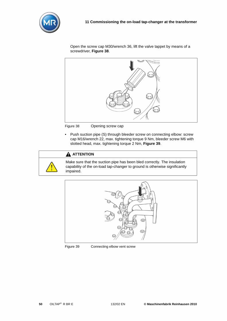
Open the screw cap M30/wrench 36, lift the valve tappet by means of a screwdriver, Figure 38.
• Push suction pipe (S) through bleeder screw on connecting elbow: screw cap M16/wrench 22, max. tightening torque 9 Nm, bleeder screw M6 with slotted head, max. tightening torque 2 Nm, Figure 39.
Figure 38 Opening screw cap
ATTENTION
Make sure that the suction pipe has been bled correctly. The insulation capability of the on-load tap-changer to ground is otherwise significantly impaired.
Figure 39 Connecting elbow vent screw
50 OILTAP® R BR E 132/02 EN © Maschinenfabrik Reinhausen 2010
11 Commissioning the on-load tap-changer at the transformer
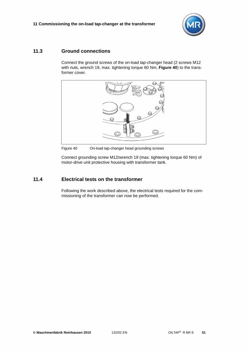
11.3 Ground connections
Connect the ground screws of the on-load tap-changer head (2 screws M12 with nuts, wrench 19, max. tightening torque 60 Nm, Figure 40) to the trans-former cover.
Connect grounding screw M12/wrench 19 (max. tightening torque 60 Nm) of motor-drive unit protective housing with transformer tank.
11.4 Electrical tests on the transformer
Following the work described above, the electrical tests required for the com-missioning of the transformer can now be performed.
Figure 40 On-load tap-changer head grounding screws
© Maschinenfabrik Reinhausen 2010 132/02 EN OILTAP® R BR E 51

12 Transportation to the operating site
12 Transportation to the operating site
If the motor-drive unit has to be dismounted for the transport of the transformer to the operating site, operate the motor-drive unit into the adjustment position and then uncouple it.
It is reassembled as described under Chapter 10.1 and 10.3.
The connecting lead must run between connections E2 and Q on the on-load tap-changer head. For a short operating period of 2-4 weeks without an oil con-servator, lowering the oil level in the on-load tap-changer head by around 5 liters is sufficient.
If the transformer is to be completely emptied, drain also the switching oil of the on-load tap-changer completely.
The interior of the diverter switch oil compartment is to be conserved in the same way as the transformer (e.g. by filling with N2).
For longer immobilization periods, the motor-drive unit heating must be con-nected and operated.
ATTENTION
Do not operate the motor-drive unit while the on-load tap-changer is not coupled.
NOTE
If the transformer is filled with oil but stored or transported without oil conservator, a connecting lead must be installed between the interior of the diverter switch oil compartment and the transformer oil tank to equalize the pressure caused by the expansion of the oil.
© Maschinenfabrik Reinhausen 2010 132/02 EN OILTAP® R BR E 53

13 Commissioning at the operating site
13 Commissioning at the operating site
Before putting the transformer into service operational tests of on-load tap-changer and motor-drive unit have to be performed according to Chapter 11.1. The function of the protective relay must also be checked at this point.
A test trip of the connected circuit breakers should be made by pressing the test button ""OFF"" of the protective relay.
Make sure that closing of the circuit breakers is only possible again after the protective relay has been brought to the "IN SERVICE" position by pressing the other test button.
After energizing the transformer, tap-change operations under load can be per-formed. The switching gas accumulating under the on-load tap-changer cover will cause small amounts of oil to be displaced or will escape through the oil con-servator.
NOTE
The protective relay must be inserted into the tripping circuit of the circuit-breakers so that the transformer is immediately shut down by the circuit-breakers when the protective relay is tripped (see operating instructions no. 59 for RS 2001 the protective relay).
ATTENTION
Check that all stop valves between oil conservator and on-load tap-changer are open.
© Maschinenfabrik Reinhausen 2010 132/02 EN OILTAP® R BR E 55

14 Supervision during service, failures
14 Supervision during service, failures
Monitoring the on-load tap-changer and motor-drive unit is limited to occasional visual checks of on-load tap-changer head, protective relay and motor-drive unit.
Pay particular attention to the following:
• sealing points of the on-load tap-changer head, protective relay and con-nected pipes are to be oil-proof,
• gaskets of the protective housing of the motor-drive unit,
• correct functioning of the installed electrical heater in the protective housing of the motor-drive unit
• the condition of the control devices in the motor-drive unit.
For more serious problems with the on-load tap-changer and motor-drive unit, which cannot be easily corrected on site, or if the protective relay has been tripped, please inform your authorized MR representative, the transformer man-ufacturer or contact us directly at:
Maschinenfabrik Reinhausen GmbHTechnischer ServicePostfach 12 03 60D-93025 RegensburgTel.: (+49) 9 41 / 40 90-0Fax: (+49) 9 41 / 40 90-501Telex: 65881
WARNING
If the protective relay is triggered, the on-load tap-changer and transformer must be thoroughly checked. To do this, remove the diverter switch insert and check as described in the inspection instructions. Proceed in detail according to Operating Instructions No. 59 for the protective relay RS 2001.
Do not use the equipment again until you are sure there is no damage to the on-load tap-changer or transformer.
Energizing the transformer without prior checking is not permitted as serious damage to the on-load tap-changer and the transformer can occur.
© Maschinenfabrik Reinhausen 2010 132/02 EN OILTAP® R BR E 57

15 Inspections
15 Inspections
The inspection can be carried out by qualified and MR-trained personnel usually within one day, provided it is well prepared and organized.
We generally recommend to have inspection carried out by our Technical Service.
This guarantees a professional performance of the inspection and ensures the updating of specific components to the latest operational state.
If the inspection is not to be carried out by MR personnel, we recommend that you ask for a quotation of the spare parts required for the inspection (please quote the on-load tap-changer serial number and the number of switching oper-ations).
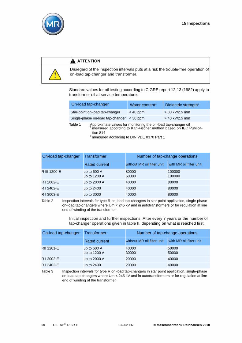
The numbers of tap-change operations determining the inspection intervals indicated in Table II and Table III are figures based on experience with use of usual oil qualities.|
The tap selector in the on-load tap-changer does not require any maintenance. In special cases, however, for example in industrial transformers where high numbers of tap-change operations are to be expected, our technical service department must be contacted after about 1,000,000 tap-change operations.
The diverter switch insert in the on-load tap-changer must be replaced after 800,000 tap-change operations at the latest.The protective relay must be con-nected The protective relay must be connected
If the number of tap-change operations per year is 15,000 or higher, we recom-mend the use of our stationary oil filter unit type OF100 with a paper filter insert (see Operating Instructions BA018). Use of the oil filter unit OF 100 with com-bined filter is prescribed for all type R on-load tap-changers where Um = 300 kV (insulated to ground) and there is a linked operating voltage on the on-load tap-changer of 245…260 kV. Use of the oil filter unit OF 100 with combined filter is generally prescribed for all type R on-load tap-changers where Um = 362 kV (insulated to ground).
Filtering of the switching oil allows the inspection intervals to be extended.
The insulating oils in the transformer are to be monitored by the operator according to the appropriate rules and regulations.
If inspections are not carried out by MR personnel, we request a report to sup-plement our inspection files.
NOTE
The tap-changing equipment must be inspected at regular intervals to maintain a high level of operational safety.
© Maschinenfabrik Reinhausen 2010 132/02 EN OILTAP® R BR E 59
15 Inspections
Standard values for oil testing according to CIGRE report 12-13 (1982) apply to transformer oil at service temperature:
Initial inspection and further inspections: After every 7 years or the number of tap-changer operations given in table II, depending on what is reached first.
ATTENTION
Disregard of the inspection intervals puts at a risk the trouble-free operation of on-load tap-changer and transformer.
On-load tap-changer Water content1 Dielectric strength2
Star-point on-load tap-changer < 40 ppm > 30 kV/2.5 mm
Single-phase on-load tap-changer < 30 ppm > 40 kV/2.5 mm
Table 1 Approximate values for monitoring the on-load tap-changer oil1 measured according to Karl-Fischer method based on IEC Publica-
tion 8142 measured according to DIN VDE 0370 Part 1
On-load tap-changer Transformer Number of tap-change operations
Rated current without MR oil filter unit with MR oil filter unit
R III 1200-E up to 600 Aup to 1200 A
8000060000
100000100000
R I 2002-E up to 2000 A 40000 80000
R I 2402-E up to 2400 40000 80000
R I 3003-E up to 3000 40000 80000
Table 2 Inspection intervals for type R on-load tap-changers in star point application, single-phase on-load tap-changers where Um < 245 kV and in autotransformers or for regulation at line end of winding of the transformer.
On-load tap-changer Transformer Number of tap-change operations
Rated current without MR oil filter unit with MR oil filter unit
RII 1201-E up to 600 Aup to 1200 A
4000030000
5000050000
R I 2002-E up to 2000 A 20000 40000
R I 2402-E up to 2400 20000 40000
Table 3 Inspection intervals for type R on-load tap-changers in star point application, single-phase on-load tap-changers where Um < 245 kV and in autotransformers or for regulation at line end of winding of the transformer.
60 OILTAP® R BR E 132/02 EN © Maschinenfabrik Reinhausen 2010
15 Inspections
First inspection: after 2 years or 20,000 tap-change operations, depending on what is reached first.
Further inspections: Without MR filter unit after every 4 years, with MR filter unit (combined filter) after every 6 years or the number of operations indicated in table III – whatever is reached first.
R I 3003-E up to 3000 20000 40000
On-load tap-changer Transformer Number of tap-change operations
Rated current without MR oil filter unit with MR oil filter unit
Table 3 Inspection intervals for type R on-load tap-changers in star point application, single-phase on-load tap-changers where Um < 245 kV and in autotransformers or for regulation at line end of winding of the transformer.
© Maschinenfabrik Reinhausen 2010 132/02 EN OILTAP® R BR E 61


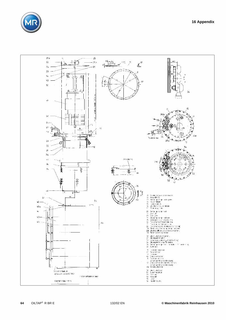
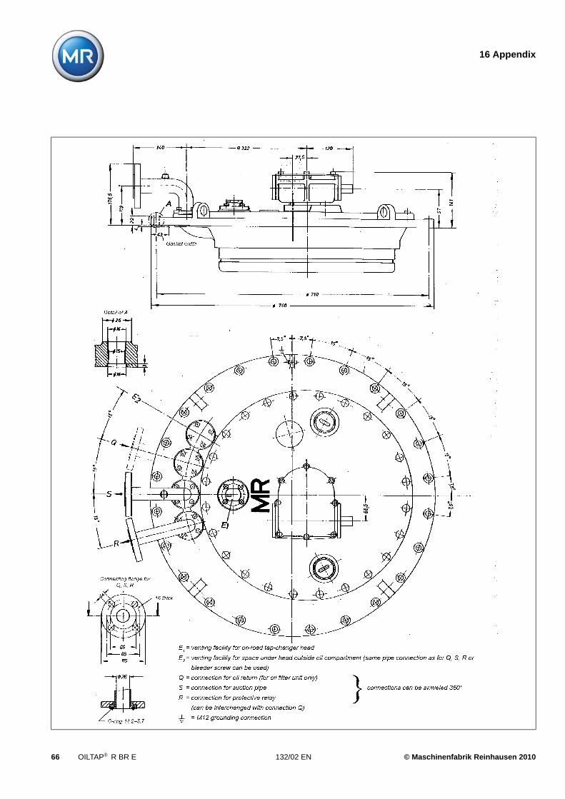
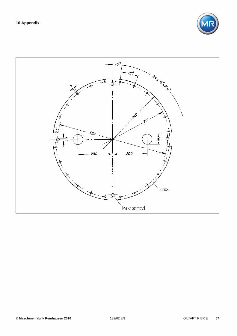
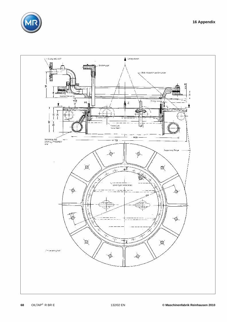
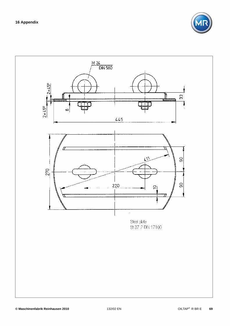
16 Appendix
16 Appendix
Installation drawing 8978730
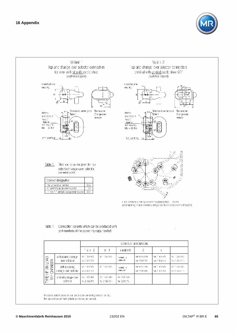
Tap and change-over selector connection terminals 8978680
On-load tap-changer head 8938998
Template for on-load tap-changer head 8901836
Supporting flange for bell-type tank installation 8967623
Lifting traverse 8901803
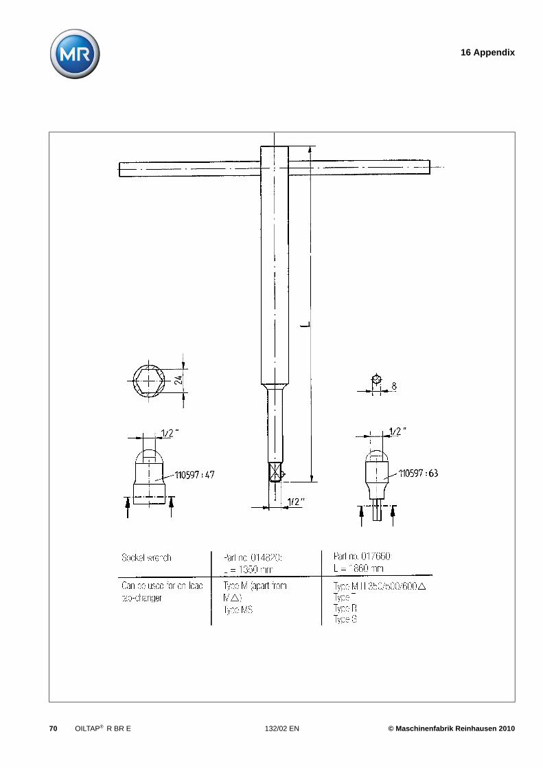
Socket wrench for kerosene drain plug 8901827
Protective relay RS 2001, dimensional drawing 8926085
Motor-drive unit MA 7, dimensional drawing 895660A
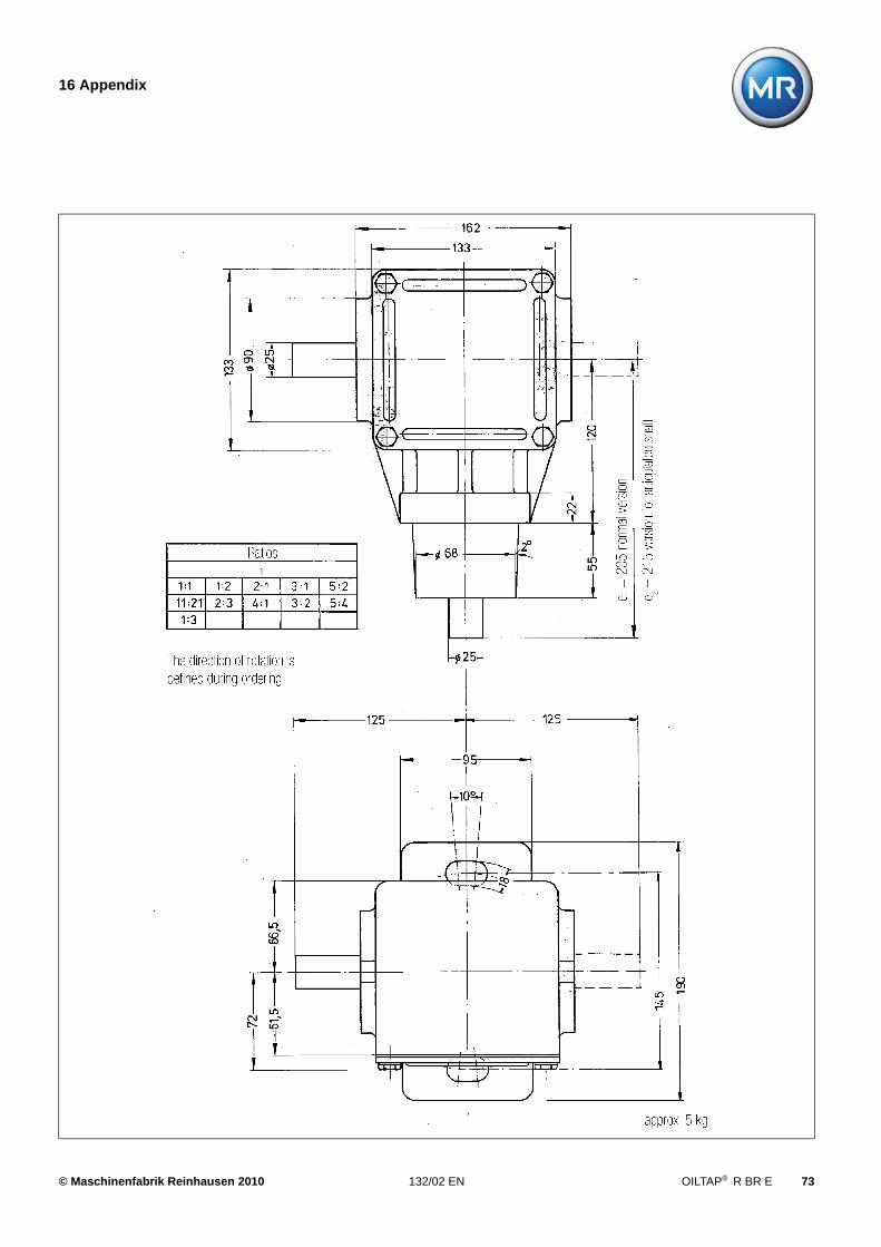
CD 6500 bevel gear, dimension drawing 8929166
© Maschinenfabrik Reinhausen 2010 132/02 EN OILTAP® R BR E 63
16 Appendix
64 OILTAP® R BR E 132/02 EN © Maschinenfabrik Reinhausen 2010
16 Appendix
© Maschinenfabrik Reinhausen 2010 132/02 EN OILTAP® R BR E 65
16 Appendix
66 OILTAP® R BR E 132/02 EN © Maschinenfabrik Reinhausen 2010
16 Appendix
© Maschinenfabrik Reinhausen 2010 132/02 EN OILTAP® R BR E 67
16 Appendix
68 OILTAP® R BR E 132/02 EN © Maschinenfabrik Reinhausen 2010
16 Appendix
© Maschinenfabrik Reinhausen 2010 132/02 EN OILTAP® R BR E 69
16 Appendix
70 OILTAP® R BR E 132/02 EN © Maschinenfabrik Reinhausen 2010
16 Appendix
© Maschinenfabrik Reinhausen 2010 132/02 EN OILTAP® R BR E 71
16 Appendix
72 OILTAP® R BR E 132/02 EN © Maschinenfabrik Reinhausen 2010
16 Appendix
© Maschinenfabrik Reinhausen 2010 132/02 EN OILTAP® R BR E 73


132/02 EN •
©Maschinenfabrik Reinhausen GmbH Tel.: +49 (0)941 4090 0Falkensteinstrasse 8 Fax: +49 (0)941 4090 7001D - 93059 Regensburg E-mail: [email protected]
www.reinhausen.com
05/10 • F0240800


![(1) DISTRICTS) BILL (2) - parliament.wa.gov.au · 388[ASSEMBLY] Mr Bertranm Mr Bryce Mr B. T. Burke Mr T. J. Burke Mr Carr Mr Davies Mr H. D. Evans Ayes Mr Laurance Mr Rushton Mr](https://img.pdfslide.us/doc/110x75/5b407eb07f8b9aff118d53d3/1-districts-bill-2-388assembly-mr-bertranm-mr-bryce-mr-b-t-burke.jpg)