Embed Size (px)
Citation preview
MR Insertable Brain PET Using Tileable GAPD Arrays
Key Jo Hong, Yong Choi, Jin Ho Jung, Jihoon Kang, Wei Hu, Hyun Keong Lim, Yoonsuk Huh, Sangsu Kim, Ji
Woong Jung, Kyu Bom Kim, Myung Sung Song and Hyun-wook Park
Abstract–The aim of this study is to develop a MR compatible
PET that is insertable to MRI and allows simultaneous PET and
MR imaging of human brain. The brain PET having 72 detector
modules arranged in a ring of 330 mm diameter was constructed
and mounted in a 3-T MRI. Each PET module composed of 4 × 4
matrix of 3 mm ×××× 3 mm ×××× 20 mm LYSO crystals coupled to a
tileable 4 ×××× 4 array Geiger-mode avalanche photodiode (GAPD)
and designed to locate between RF and gradient coils. GAPD
output charge signals were transferred to preamplifiers using flat
cable of 3 m long, and then sent to position decoder circuit (PDC)
identifying digital address and generating an analog pulse of the
one interacted channel from preamplifier signals. The PDC
outputs were fed into FPGA-embedded DAQ boards. The analog
signal was digitized, and arrival time and energy of the signal
were calculated and stored. LYSO and GAPD were located inside
MR bore and all electronics including preamplifiers were
positioned outside MR bore to minimize signal interference
between PET and MR. Simultaneous PET/MR images of a hot-
rod and Hoffman brain phantom were acquired in a 3-T MRI
using the MR compatible PET system. The rods down to a
diameter of 3.5 mm were resolved in the hot-rod PET image.
Activity distribution patterns between white and gray matter in
Hoffman brain phantom were well imaged. No degradation of
image quality of the hot-rod and Hoffman brain phantoms on the
simultaneously acquired MR images obtained with standard
sequences was observed. These results demonstrate that
simultaneous acquisition of PET and MR images is feasible using
the MR insertable PET developed in this study.
I. INTRODUCTION
ECENTLY, positron emission tomography (PET) has evolved
into multi-modality imaging systems obtaining quantitative
functional information with accurate anatomical detail [1]. PET
combined with computed tomography (CT) has been widely
utilized in clinical and preclinical studies. As a subsequent
advancement, a combination of PET and magnetic resonance
imaging (MRI) has been proposed, not only because of the
absence of ionizing radiation from MRI but also for its
excellent soft-tissue contrast and its capability to perform
Manuscript received November 18, 2010. This study was supported by a
grant of the Converging Research Center Program through the National
Research Foundation of Korea (NRF) funded by the Ministry of Education,
Science and Technology (2009-0081935), and by a grant of the Technology
Innovation Program funded by, the Ministry of Knowledge Economy
(10030029), Republic of Korea.
Key Jo Hong, Yong Choi, Jin Ho Jung, Jihoon Kang, Wei Hu, Hyun Keong
Lim, Yoonsuk Huh, Sangsu Kim, Ji Woong Jung and Kyu Bom Kim are with
the Department of Electronic Engineering, Sogang University, 1 Shinsu-Dong,
Mapo-Gu, Seoul, 121-742, Republic of Korea (telephone: +82-2-705-8910, e-
mail: [email protected], [email protected]).
Myung Sung Song and Hyun-wook Park are with fMRI Laboratory N23,
Department of Electrical Engineering, Korea Advanced Institute of Science
and Technology, 373-1, Guseong-dong, Yuseong-gu, Daejeon, 305-701,
Republic of Korea.
diffusion imaging, magnetic resonance spectroscopy (MRS)
and functional MRI (fMRI) [2-4]. Thus, current developments
on PET detector technology are focusing on the combination of
PET and MRI to obtain simultaneous images from both
modalities [5, 6].
The aim of this study is to develop a MR compatible PET
using the GAPD that is insertable to MRI and allows
simultaneous PET and MR imaging of human brain.
II. MATERIALS AND METHODS
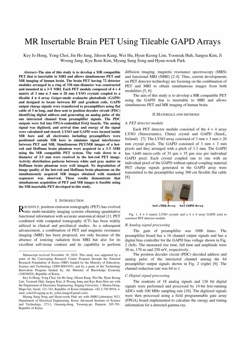
A. PET detector module
Each PET detector module consisted of the 4 × 4 array
LYSO (Sinoceramics, China) crystal and GAPD (SensL,
Ireland). [7]. The LYSO array consisted of 3 mm × 3 mm × 20
mm crystal pixels. The GAPD consisted of 3 mm × 3 mm
pixels and they arranged with a pitch of 3.3 mm. The GAPD
has 3,640 micro-cells of 35 µm × 35 µm size per individual
GAPD pixel. Each crystal coupled one to one with an
individual pixel of the GAPD without optical-coupling material.
PET charge signals generated in the GAPD array were
transmitted to the preamplifier using 300 cm flexible flat cable
[8].
Fig. 1. 4 × 4 matrix LYSO crystals and a 4 × 4 array GAPD used to
construct PET detector module.
B. Analog signal processing
The gain of preamplifier was 1000 times. The
preamplifier board has a 16 channel output signals and has a
digital bias controller for the GAPD bias voltage shown in Fig.
2 (left). The measured rise time, fall time and amplitude were
30 ns, 170 ns and 250 mV, respectively.
The position decoder circuit (PDC) decoded address and
analog pulse of the interacted channel among the 64
preamplifier output signals shown in Fig. 2 (right) [9]. The
channel reduction rate was 64 to 1.
C. Digital signal processing
The readouts of 18 analog signals and 126 bit digital
signals were performed and processed by 14-bit free-running
ADCs with 100 MHz sampling rate [10]. The digitized signals
were then processed using a field programmable gate array
(FPGA) board implemented to calculate the energy and timing
information for a detected gamma ray.
R
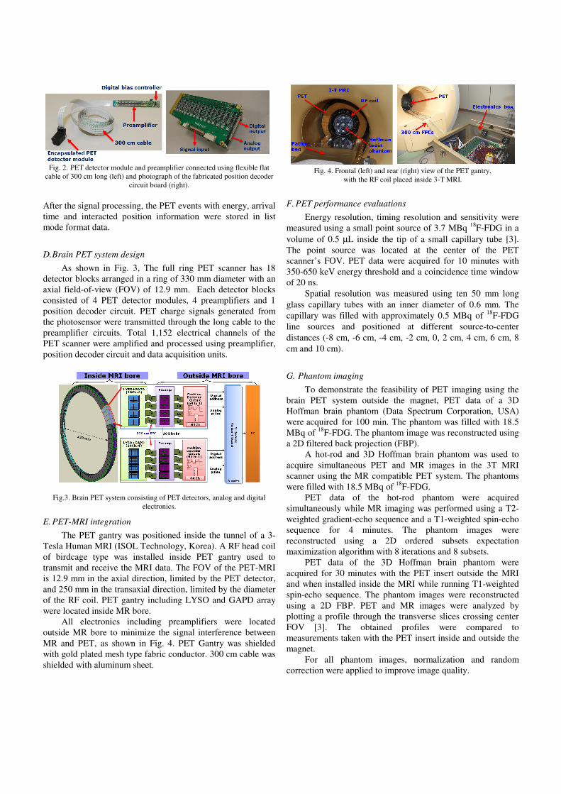
Fig. 2. PET detector module and preamplifier connected using flexible flat
cable of 300 cm long (left) and photograph of the fabricated position decoder
circuit board (right).
After the signal processing, the PET events with energy, arrival
time and interacted position information were stored in list
mode format data.
D. Brain PET system design
As shown in Fig. 3, The full ring PET scanner has 18
detector blocks arranged in a ring of 330 mm diameter with an
axial field-of-view (FOV) of 12.9 mm. Each detector blocks
consisted of 4 PET detector modules, 4 preamplifiers and 1
position decoder circuit. PET charge signals generated from
the photosensor were transmitted through the long cable to the
preamplifier circuits. Total 1,152 electrical channels of the
PET scanner were amplified and processed using preamplifier,
position decoder circuit and data acquisition units.
Fig.3. Brain PET system consisting of PET detectors, analog and digital
electronics.
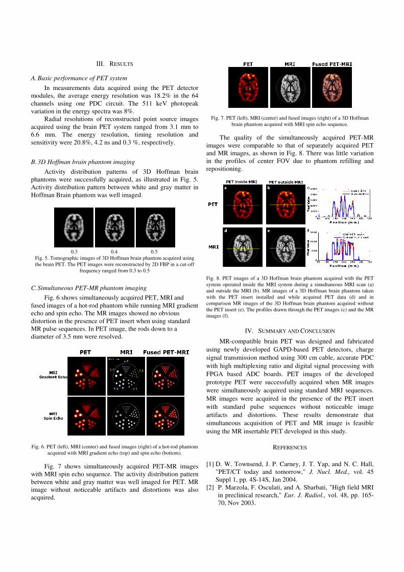
E. PET-MRI integration
The PET gantry was positioned inside the tunnel of a 3-
Tesla Human MRI (ISOL Technology, Korea). A RF head coil
of birdcage type was installed inside PET gantry used to
transmit and receive the MRI data. The FOV of the PET-MRI
is 12.9 mm in the axial direction, limited by the PET detector,
and 250 mm in the transaxial direction, limited by the diameter
of the RF coil. PET gantry including LYSO and GAPD array
were located inside MR bore.
All electronics including preamplifiers were located
outside MR bore to minimize the signal interference between
MR and PET, as shown in Fig. 4. PET Gantry was shielded
with gold plated mesh type fabric conductor. 300 cm cable was
shielded with aluminum sheet.
Fig. 4. Frontal (left) and rear (right) view of the PET gantry,
with the RF coil placed inside 3-T MRI.
F. PET performance evaluations
Energy resolution, timing resolution and sensitivity were
measured using a small point source of 3.7 MBq 18
F-FDG in a
volume of 0.5 µL inside the tip of a small capillary tube [3].
The point source was located at the center of the PET
scanner’s FOV. PET data were acquired for 10 minutes with
350-650 keV energy threshold and a coincidence time window
of 20 ns.
Spatial resolution was measured using ten 50 mm long
glass capillary tubes with an inner diameter of 0.6 mm. The
capillary was filled with approximately 0.5 MBq of 18
F-FDG
line sources and positioned at different source-to-center
distances (-8 cm, -6 cm, -4 cm, -2 cm, 0, 2 cm, 4 cm, 6 cm, 8
cm and 10 cm).
G. Phantom imaging
To demonstrate the feasibility of PET imaging using the
brain PET system outside the magnet, PET data of a 3D
Hoffman brain phantom (Data Spectrum Corporation, USA)
were acquired for 100 min. The phantom was filled with 18.5
MBq of 18
F-FDG. The phantom image was reconstructed using
a 2D filtered back projection (FBP).
A hot-rod and 3D Hoffman brain phantom was used to
acquire simultaneous PET and MR images in the 3T MRI
scanner using the MR compatible PET system. The phantoms
were filled with 18.5 MBq of 18
F-FDG.
PET data of the hot-rod phantom were acquired
simultaneously while MR imaging was performed using a T2-
weighted gradient-echo sequence and a T1-weighted spin-echo
sequence for 4 minutes. The phantom images were
reconstructed using a 2D ordered subsets expectation
maximization algorithm with 8 iterations and 8 subsets.
PET data of the 3D Hoffman brain phantom were
acquired for 30 minutes with the PET insert outside the MRI
and when installed inside the MRI while running T1-weighted
spin-echo sequence. The phantom images were reconstructed
using a 2D FBP. PET and MR images were analyzed by
plotting a profile through the transverse slices crossing center
FOV [3]. The obtained profiles were compared to
measurements taken with the PET insert inside and outside the
magnet.
For all phantom images, normalization and random
correction were applied to improve image quality.
III. RESULTS
A. Basic performance of PET system
In measurements data acquired using the PET detector
modules, the average energy resolution was 18.2% in the 64
channels using one PDC circuit. The 511 keV photopeak
variation in the energy spectra was 8%.
Radial resolutions of reconstructed point source images
acquired using the brain PET system ranged from 3.1 mm to
6.6 mm. The energy resolution, timing resolution and
sensitivity were 20.8%, 4.2 ns and 0.3 %, respectively.
B. 3D Hoffman brain phantom imaging
Activity distribution patterns of 3D Hoffman brain
phantoms were successfully acquired, as illustrated in Fig. 5.
Activity distribution pattern between white and gray matter in
Hoffman Brain phantom was well imaged.
0.3 0.4 0.5
Fig. 5. Tomographic images of 3D Hoffman brain phantom acquired using
the brain PET. The PET images were reconstructed by 2D FBP in a cut-off
frequency ranged from 0.3 to 0.5
C. Simultaneous PET-MR phantom imaging
Fig. 6 shows simultaneously acquired PET, MRI and
fused images of a hot-rod phantom while running MRI gradient
echo and spin echo. The MR images showed no obvious
distortion in the presence of PET insert when using standard
MR pulse sequences. In PET image, the rods down to a
diameter of 3.5 mm were resolved.
Fig. 6. PET (left), MRI (center) and fused images (right) of a hot-rod phantom
acquired with MRI gradient echo (top) and spin echo (bottom).
Fig. 7 shows simultaneously acquired PET-MR images
with MRI spin echo sequence. The activity distribution pattern
between white and gray matter was well imaged for PET. MR
image without noticeable artifacts and distortions was also
acquired.
Fig. 7. PET (left), MRI (center) and fused images (right) of a 3D Hoffman
brain phantom acquired with MRI spin echo sequence.
.
The quality of the simultaneously acquired PET-MR
images were comparable to that of separately acquired PET
and MR images, as shown in Fig. 8. There was little variation
in the profiles of center FOV due to phantom refilling and
repositioning.
Fig. 8. PET images of a 3D Hoffman brain phantom acquired with the PET
system operated inside the MRI system during a simultaneous MRI scan (a)
and outside the MRI (b). MR images of a 3D Hoffman brain phantom taken
with the PET insert installed and while acquired PET data (d) and in
comparison MR images of the 3D Hoffman brain phantom acquired without
the PET insert (e). The profiles drawn through the PET images (c) and the MR
images (f).
IV. SUMMARY AND CONCLUSION
MR-compatible brain PET was designed and fabricated
using newly developed GAPD-based PET detectors, charge
signal transmission method using 300 cm cable, accurate PDC
with high multiplexing ratio and digital signal processing with
FPGA based ADC boards. PET images of the developed
prototype PET were successfully acquired when MR images
were simultaneously acquired using standard MRI sequences.
MR images were acquired in the presence of the PET insert
with standard pulse sequences without noticeable image
artifacts and distortions. These results demonstrate that
simultaneous acquisition of PET and MR image is feasible
using the MR insertable PET developed in this study.
REFERENCES
[1] D. W. Townsend, J. P. Carney, J. T. Yap, and N. C. Hall,
"PET/CT today and tomorrow," J. Nucl. Med., vol. 45
Suppl 1, pp. 4S-14S, Jan 2004.
[2] P. Marzola, F. Osculati, and A. Sbarbati, "High field MRI
in preclinical research," Eur. J. Radiol., vol. 48, pp. 165-
70, Nov 2003.
[3] M. S. Judenhofer, H. F. Wehrl, D. F. Newport, C. Catana,
S. B. Siegel, M. Becker, A. Thielscher, M. Kneilling, M. P.
Lichy, M. Eichner, K. Klingel, G. Reischl, S. Widmaier,
M. Rocken, R. E. Nutt, H. J. Machulla, K. Uludag, S. R.
Cherry, C. D. Claussen, and B. J. Pichler, "Simultaneous
PET-MRI: a new approach for functional and
morphological imaging," Nature Med., vol. 14, pp. 459-65,
Apr 2008.
[4] B. J. Pichler, H. F. Wehrl, A. Kolb, and M. S. Judenhofer,
"Positron Emission Tomography/Magnetic Resonance
Imaging: The Next Generation of Multimodality
Imaging?," Seminars in nuclear medicine, vol. 38, pp.
199-208, 2008.
[5] M. S. Judenhofer, C. Catana, B. K. Swann, S. B. Siegel, W.
I. Jung, R. E. Nutt, S. R. Cherry, C. D. Claussen, and B. J.
Pichler, "PET/MR Images Acquired with a Compact MR-
compatible PET Detector in a 7-T Magnet," Radiology,
vol. 244, pp. 807-814, 2007.
[6] R. R. Raylman, S. Majewski, S. S. Velan, S. Lemieux, B.
Kross, V. Popov, M. F. Smith, and A. G. Weisenberger,
"Simultaneous acquisition of magnetic resonance
spectroscopy (MRS) data and positron emission
tomography (PET) images with a prototype MR-
compatible, small animal PET imager," J. Magn. Reson.,
vol. 186, pp. 305-10, Jun 2007.
[7] K. J. Hong, Y. Choi, J. H. Kang, W. Hu, J. H. Jung, B. J.
Min, H. K. Lim, S. H. Shin, Y. S. Huh, Y. H. Chung, P.
Hughes, and C. Jackson, "Development of PET using 4 x
4 array of large size Geiger-mode avalanche photodiode,"
in Nuclear Science Symposium Conference Record
(NSS/MIC), 2009 IEEE, 2009, pp. 3032-3037.
[8] J. Kang, Y. Choi, K. J. Hong, J. H. Jung, W. Hu, Y. S.
Huh, H. Lim, and B.-T. Kim, "A feasibility study of
photosensor charge signal transmission to preamplifier
using long cable for development of hybrid PET-MRI,"
Med. Phys., vol. 37, pp. 5655-5664, 2010.
[9] J. H. Jung, Y. Choi, K. J. Hong, W. Hu, J. H. Kang, B. J.
Min, S. H. Shin, H. K. Lim, Y. S. Huh, and E. J. Kim,
"Development of a position decoder circuit for PET
consisting of GAPD arrays," Nucl. Instrum. Meth. Phys.
Res. Sec. A-Accelerators, Spectrometers, Detectors, and
Associated equipment, vol. 621, pp. 310-315, Sep 2010.
[10] W. Hu, Y. Choi, K. J. Hong, J. Kang, J. H. Jung, Y. S.
Huh, H. K. Lim, S. S. Kim, B. J. Min, and B.-T. Kim, "A
simple and improved digital timing method for positron
emission tomography," Nucl. Instrum. Meth. Phys. Res.
Sec. A-Accelerators, Spectrometers, Detectors, and
Associated equipment, vol. 622, pp. 219-224, 2010.


![Avalanche Process in Semiconductor Photo …...Avalanche Process in Semiconductor Photo Dete ctors in the Context of the Feedback Theory 211 (GAPD) [4], the probability interpretation](https://img.pdfslide.us/doc/110x75/5f7258bb22584903557bd3a0/avalanche-process-in-semiconductor-photo-avalanche-process-in-semiconductor.jpg)