Embed Size (px)
Citation preview

Imagination at work
MR Gradient Cable Field Termination Training
Field Service TrainingDOC2081583
Brian Gracyalny 212473777 MR Service Engineering

Overview
Learning ObjectivesUpon completing this training, you will be able to: Understand gradient potential safety issue Failure mode of improperly terminated leads Understand proper tooling and termination Proper attachment of leads to gradient filter
AudienceThis course is required for all GEHC Field Engineers, Mechanical Installers, Bay Technicians, and Service Engineers.
Module LengthThis module takes about 15 minutes to complete.
Course CompletionYou must complete the learning module and the assessment (80% or higher) to get credit for this course.
The purpose of this training is to make the field aware of a potential safety issue with improperly terminated gradient cable leads and demonstrate the proper tooling and procedure.
GEHC Learning Module: MR Gradient Cable Field Termination

See tutorial regarding confidentiality disclosures. Delete if not needed.
Lesson 1: Gradient Filter Theory
Lesson 2: Gradient Cable Termination Failures
Lesson 3: Improper Gradient Cable Termination
Lesson 4: Identification of the Gradient Terminals
Lesson 5: Proper Termination of Gradient Terminals
Lesson 6: Gradient Cable Tool Kit
Looking Forward
Summary Field Actions
3
Contents
GEHC Learning Module: MR Gradient Cable Field Termination

See tutorial regarding confidentiality disclosures. Delete if not needed.
Lesson 1: Gradient Filter TheoryThe gradient filter in MR systems is used to attenuate differential and common mode RF noise on the gradient leads. At the base of the gradient filter, mounted on the secondary penetration wall, you’ll find the filter terminations for the X+, X-, Y+, Y- and , Z+, Z- and ground leads.
4
Gradient Filter Passes Though PEN
Wall
Gradient Filter
GEHC Learning Module: MR Gradient Cable Field Termination

See tutorial regarding confidentiality disclosures. Delete if not needed.
Lesson 2: Improper Termination Failure
5GEHC Learning Module: MR Gradient Cable Field Termination
1. Improperly crimped gradient cables will lead to Gradient Distortion Faults, indicated with an error code: ovrlErr.
2. After TPS reset and depending on the Pulse Sequence prescribed, a poor electrical connection will increase the resistivity of this connection, leading to electrical arcing and excessive heating.
3. A cross section of the cable in the lug shows voids that prevents a hermetic seal during crimp (air tight connection to prevent oxidation).

See tutorial regarding confidentiality disclosures. Delete if not needed.
Lesson 3: Improper Gradient Cable Termination
6
Loose Strands Loose strands not extending through the lug
barrel increases resistance and limit the current capacity of the gradient lead, resulting in Gradient Distortion Faults.
Severed StrandsSevered strands create localized heating,
forcing the gradient driver to compensate for resistive losses.
Poor Crimp QualityMechanical retention force is reduced,
resulting in detachment and increase in resistivity due to oxidation of the copper wires.
GEHC Learning Module: MR Gradient Cable Field Termination

See tutorial regarding confidentiality disclosures. Delete if not needed.
Lesson 4: Identification of the Gradient TerminalsThe terminals used for the gradient cable are color-keyed to match the color-keyed crimper die.
1. Terminal mating area
2. End bell mouth
3. Conductor crimp area
4. Entry bell mouth
5. Brush inspection window
Insulation should not extend into the barrel and be less than 2 wire bundles from lug.
7GEHC Learning Module: MR Gradient Cable Field Termination

See tutorial regarding confidentiality disclosures. Delete if not needed.
Example of Good vs. Bad Termination
8
All strands must be in the lug barrel, no frays allowed
Crimps must be centered within the crimp area with leads extending to the bell mouth
No scored or cut leads, all strands must be in the barrel
No variation in strand length shall exist that prevents installation to the full depth of the crimp contact area.
1 2
GEHC Learning Module: MR Gradient Cable Field Termination
1
1 2

See tutorial regarding confidentiality disclosures. Delete if not needed.
Lesson 5: Proper Termination of Gradient Cable Stripping the Cable Jacket
Before cutting the outer jacket, place the large hook onto the stripper, removing the small hook
(1) Large hook
(2) Stripper tool
(3) Hook release
Position the wire stripper and adjust the blade depth to the minimum thickness of the outer jacket
(1) Blade
(2) Outer jacket
Place the stripper to the desired mark and rotate the tool clockwise around jacket (marked ‘ – ‘ on the tool). Pull back on the handle to remove the blade from the jacket material, rotate the blade 90º (marked ‘ | ’ on the tool), and allow the tool to re-enter the material to strip lengthwise to the end of the cable.
(1) Rotate tool around the jacket
(2) Rotate blade 90º
(3) Strip the jacket lengthwise
9
Careful not to cut through the braided shield.
GEHC Learning Module: MR Gradient Cable Field Termination

See tutorial regarding confidentiality disclosures. Delete if not needed.
Measure and mark 3.5 in. from the edge of the outer jacket and push the braid to this mark to form a safe cutting area – cut of the remaining braided shield with a diagonal cutter or shear wire cutter—do not use a knife for this procedure, this may cut into the gradient leads.
Remove the nylon gradient cable filler up to the end of the braid – exposing the 4 gradient leads + 1 gradient ground
Secure the braid with electrical tape to prevent unraveling of the braid – this is the only place to use electrical tape, the gradient leads must be available for inspection.
10
Do no use a knife to cut the braid, this may cut into the gradient leads.GEHC Learning Module: MR Gradient Cable Field Termination
Lesson 5: Proper Termination of Gradient Cable
Remove the foil shield exposing the braided shield(1) Foil shield(2) Braided shield

See tutorial regarding confidentiality disclosures. Delete if not needed.
Lesson 5: Proper Termination of Gradient Cable
Use the lug to determine the strip length and mark the gradient lead.
Replace the large hook, used on the outer jacket, with the small hook, used for the gradient leads.
Position the stripper over the end of the gradient lead and set the blade depth.
Place the tool on the mark, with the blade on the ‘ – ‘ mark, rotate the tool clockwise. Pull back on the handle to remove the blade from the material and rotate the blade to the ‘ | ‘ mark to strip lengthwise. The insulation is removed without cutting or scoring the gradient leads.
11
Position the X, Y, and Z gradient cables on the U-bolt and tighten around the braided shield – note the back to back position of the terminals attached to the studs. Before crimping terminals onto the leads, position and mark the cable alignment to ease fastening the terminals to the studs.
GEHC Learning Module: MR Gradient Cable Field Termination
Do not touch the wire strands with the blade.

See tutorial regarding confidentiality disclosures. Delete if not needed.
Lesson 5: Proper Termination of Gradient Cable Crimping the Terminals
Align the crimper so that the die is between the color-keyed marks
1. Gradient lead
2. Die
3. Lug
4. Crimp tool
Apply steady pressure all the way through the crimp process (tool will release when crimp is complete)
Place the lugs back-to-back on the gradient filter
Secure with the Spiralock nut, using the two wrench method, hold the hex nut while tightening the Spiralock.
1. Hex nut
2. Spiralock nut
12GEHC Learning Module: MR Gradient Cable Field Termination
Remember to align the lug on the mark, prior to crimping, to avoid stress on the lead.
See tutorial regarding confidentiality disclosures. Delete if not needed. 13
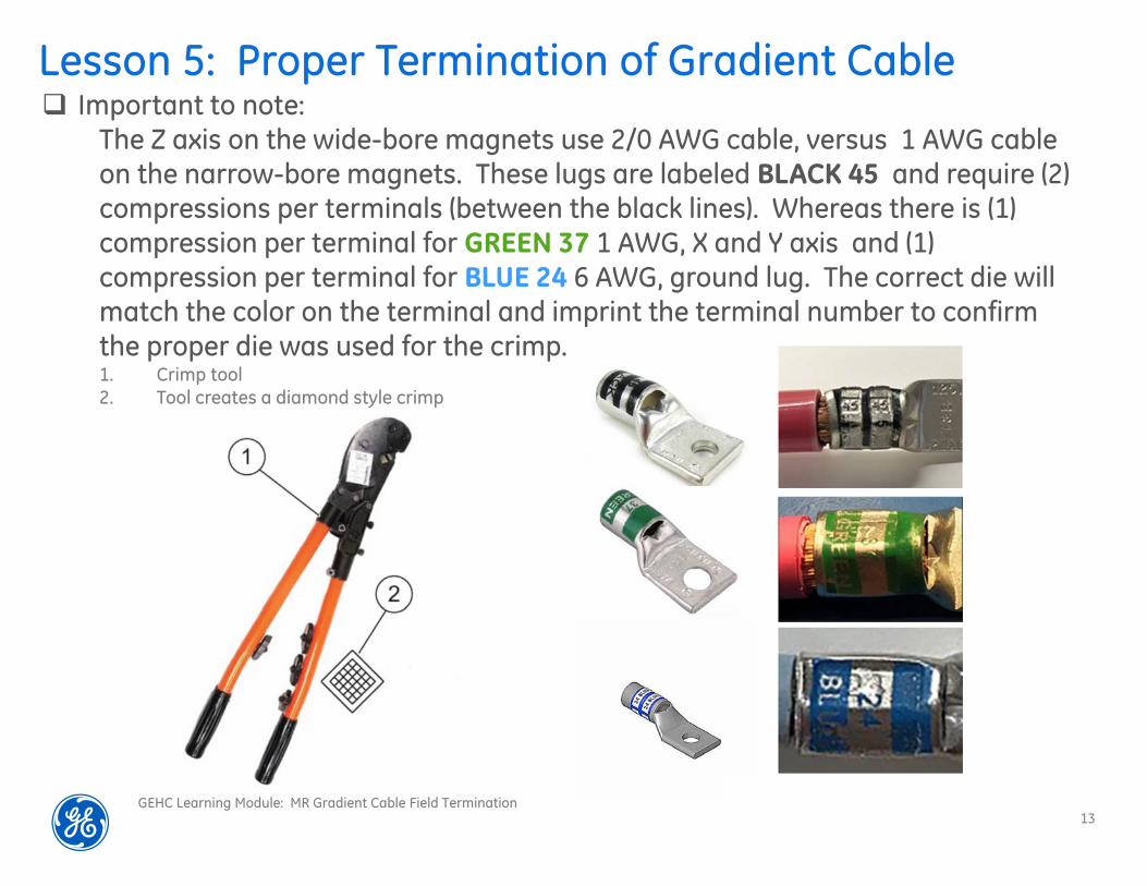
Lesson 5: Proper Termination of Gradient Cable Important to note:
The Z axis on the wide-bore magnets use 2/0 AWG cable, versus 1 AWG cable on the narrow-bore magnets. These lugs are labeled BLACK 45 and require (2) compressions per terminals (between the black lines). Whereas there is (1) compression per terminal for GREEN 37 1 AWG, X and Y axis and (1) compression per terminal for BLUE 24 6 AWG, ground lug. The correct die will match the color on the terminal and imprint the terminal number to confirm the proper die was used for the crimp.1. Crimp tool2. Tool creates a diamond style crimp
GEHC Learning Module: MR Gradient Cable Field Termination

See tutorial regarding confidentiality disclosures. Delete if not needed.
Lesson 6: Gradient Cable Tool Kit
Gradient Cable Tool Kit: 5790054 5790056 Thomas & Betts Crimper model TBM5-S
5790057 Greenlee Cable Cutter model 45207
5790059 Greenlee Insulation Stripper model 1903
5790061 Greenlee Replacement Blades 13544
5790062 BAUSCH & LOMB 10X Magnification Inspection Loupe model 81-41-70
5790064 Laminated inventory list and supplier work instructions
5790053 Hard shell, sealed, latched flight case with handle, wheels, and custom formed foam interior to hold each tool
Note: This tool is highly ferrous and should not be brought into a ramped scan room!
14
Required tool available through the tool depot: Gradient Cable Tool Kit 5790054
GEHC Learning Module: MR Gradient Cable Field Termination

See tutorial regarding confidentiality disclosures. Delete if not needed.
Looking Forward:
15
GE Engineering is working on an extensive quality effort to ensure Safety First our scanners. It’s important for us to understand the failure modes and practice preventative actions to ensure customer confidence in our products. We’ll be collecting PIM data from our installs to determine a factory pre-crimped solution for the future.
GEHC Learning Module: MR Gradient Cable Field Termination

See tutorial regarding confidentiality disclosures. Delete if not needed.
Summary: Field Actions
16
Only use the recommended service tools listed in each install manual and MR Service Documentation.
Do not score or cut any of 800 strands of 30 AWG wire (1 AWG), they’re critical to create a hermetic seal.
Be careful to have the all the strands in the lug and positioned back-to-back prior to the crimp.
Allow slack in the gradient cables when you’re routing them to the pen wall, this will allow for remediation if necessary.
GEHC Learning Module: MR Gradient Cable Field Termination


![The Conjugate Gradient Method...Conjugate Gradient Algorithm [Conjugate Gradient Iteration] The positive definite linear system Ax = b is solved by the conjugate gradient method](https://img.pdfslide.us/doc/110x75/5e95c1e7f0d0d02fb330942a/the-conjugate-gradient-method-conjugate-gradient-algorithm-conjugate-gradient.jpg)