Embed Size (px)
Citation preview
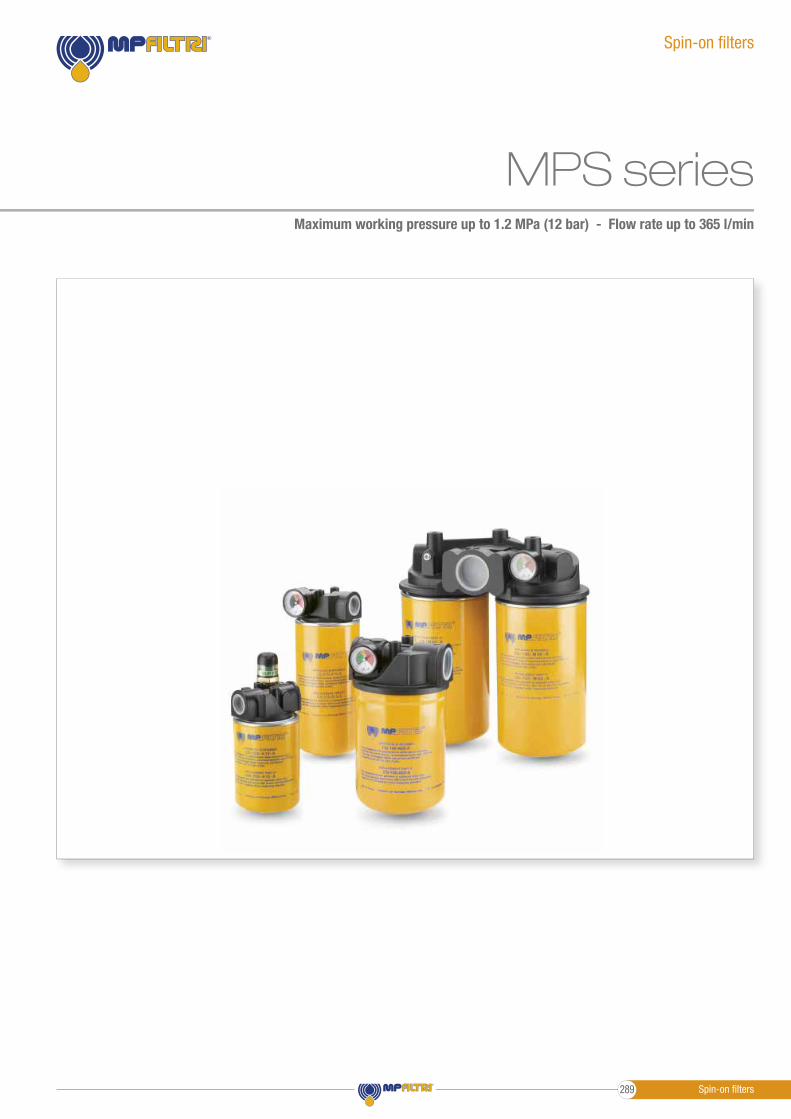
MPS seriesMaximum working pressure up to 1.2 MPa (12 bar) - Flow rate up to 365 l/min
Spin-on fi lters
Spin-on fi lters289
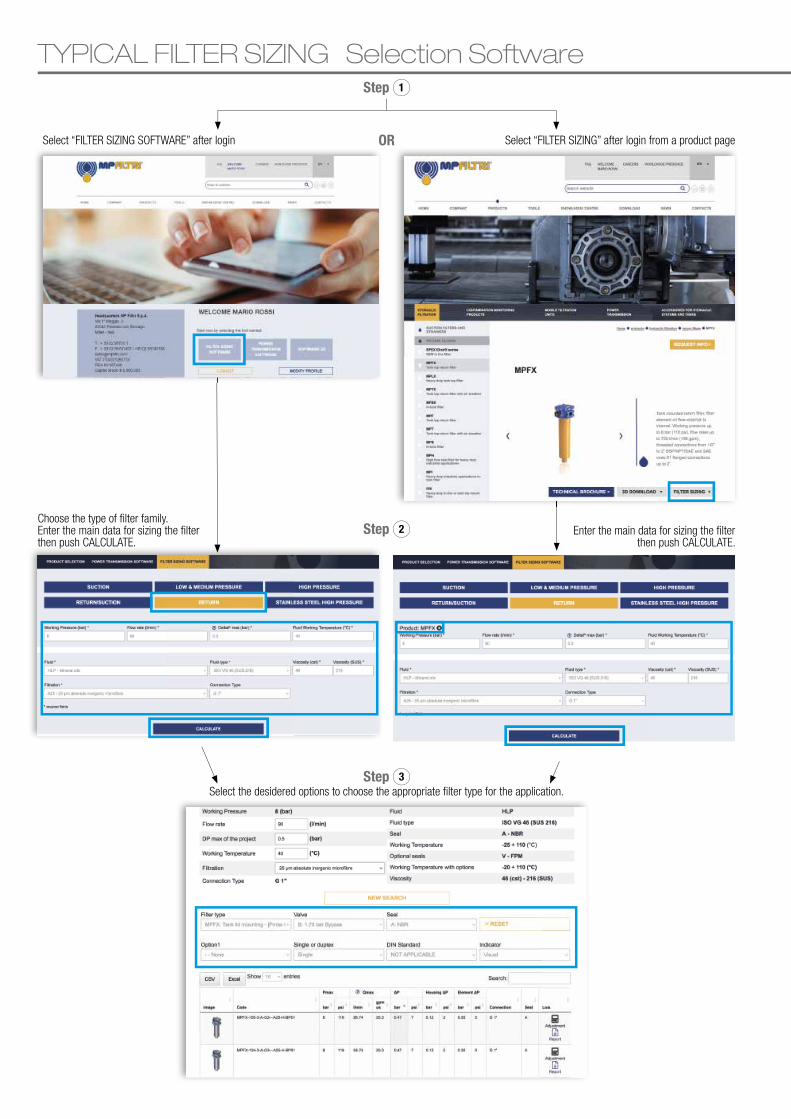
TYPICAL FILTER SIZING Selection Software
Select “FILTER SIZING SOFTWARE” after login Select “FILTER SIZING” after login from a product pageOR
Step 1
Step 2
Step 3
Choose the type of � lter family.Enter the main data for sizing the � lterthen push CALCULATE.
Enter the main data for sizing the � lterthen push CALCULATE.
Select the desidered options to choose the appropriate � lter type for the application.
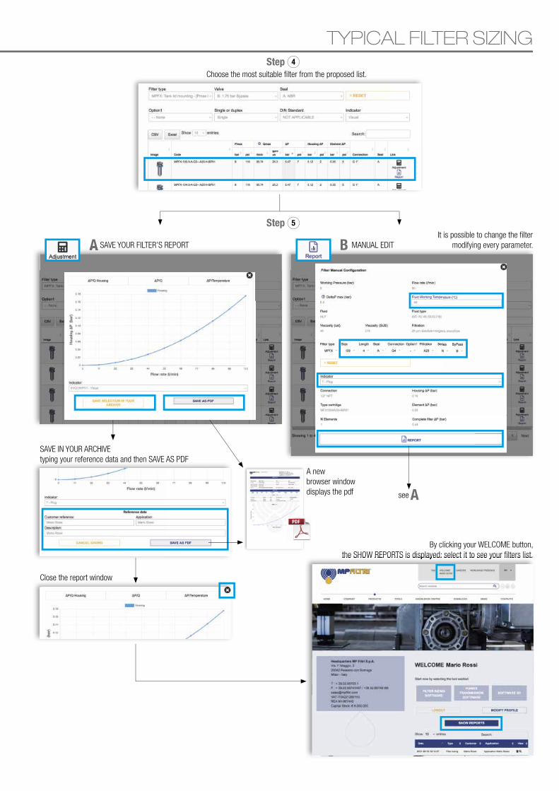
TYPICAL FILTER SIZING
A B
Step 4
Step 5
Choose the most suitable � lter from the proposed list.
A SAVE YOUR FILTER’S REPORT
A
It is possible to change the � lter modifying every parameter.MANUAL EDIT
see
A new browser window displays the pdf
SAVE IN YOUR ARCHIVEtyping your reference data and then SAVE AS PDF
By clicking your WELCOME button,the SHOW REPORTS is displayed: select it to see your � lters list.
Close the report window
the SHOW REPORTS is displayed: select it to see your � lters list.
- Head: Aluminium- Bypass valve: Nylon - Steel- Element: Zinc-Plated Steel - Painted Steel
Filter housing materials
MPS
Spin-on fi lters
From -20 °C to +110 °CTemperature
- Return fi lter opening pressure: 175 kPa (1.75 bar) ±10%- Suction fi lter opening pressure: 30 kPa (0.3 bar) ±10%
Bypass valve
- ∆p: 5 bar- Fluid fl ow through the fi lter element from OUT to IN
∆p element type
Standard NBR - series ASeals
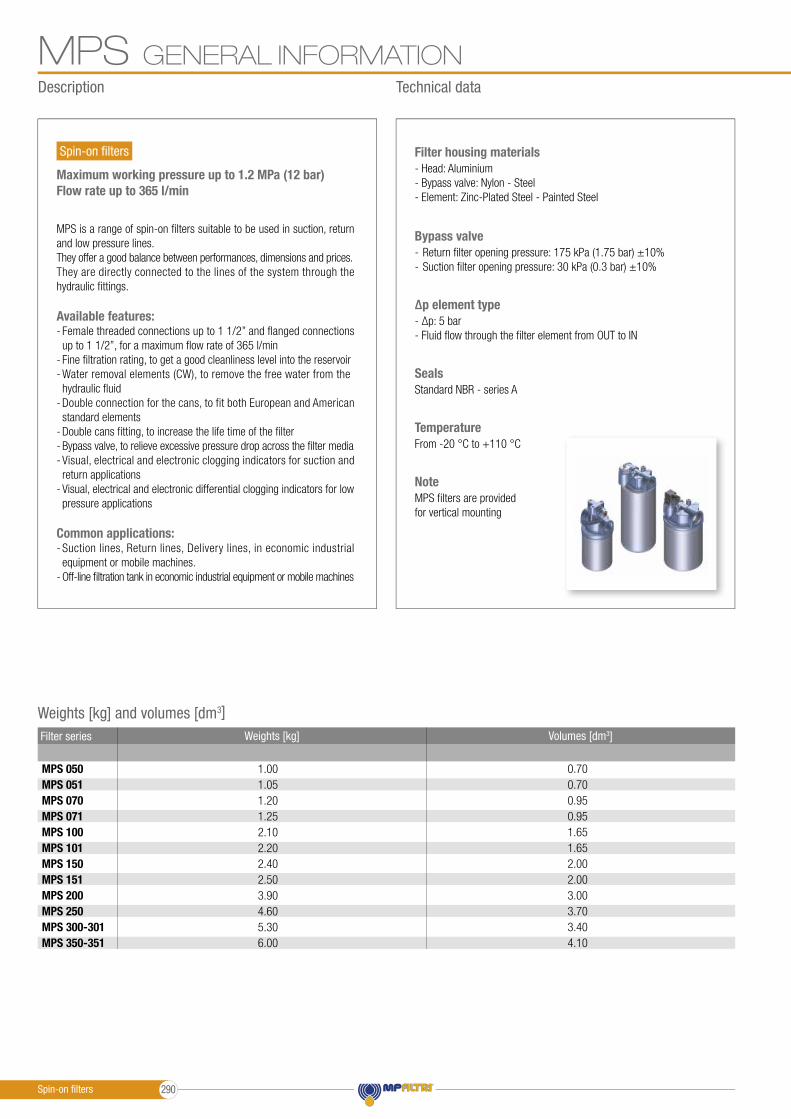
MPS fi lters are provided for vertical mounting
Note
GENERAL INFORMATION
Maximum working pressure up to 1.2 MPa (12 bar)Flow rate up to 365 l/min
MPS is a range of spin-on fi lters suitable to be used in suction, return and low pressure lines.They offer a good balance between performances, dimensions and prices.They are directly connected to the lines of the system through the hydraulic fi ttings.
Available features:- Female threaded connections up to 1 1/2” and fl anged connections up to 1 1/2”, for a maximum fl ow rate of 365 l/min- Fine fi ltration rating, to get a good cleanliness level into the reservoir- Water removal elements (CW), to remove the free water from the hydraulic fl uid- Double connection for the cans, to fit both European and American standard elements- Double cans fi tting, to increase the life time of the fi lter- Bypass valve, to relieve excessive pressure drop across the fi lter media- Visual, electrical and electronic clogging indicators for suction and return applications- Visual, electrical and electronic differential clogging indicators for low pressure applications
Common applications:- Suction lines, Return lines, Delivery lines, in economic industrial equipment or mobile machines.- Off-line fi ltration tank in economic industrial equipment or mobile machines
Weights [kg] and volumes [dm3]
1.001.051.201.252.102.202.402.503.904.605.306.00
Weights [kg]
MPS 050MPS 051MPS 070MPS 071MPS 100MPS 101MPS 150MPS 151MPS 200MPS 250MPS 300-301MPS 350-351
0.700.700.950.951.651.652.002.003.003.703.404.10
Volumes [dm3] Filter series
Description Technical data
Spin-on fi lters 290
MPSGENERAL INFORMATION
MPS 050MPS 051MPS 070MPS 071MPS 100MPS 101MPS 150MPS 151MPS 200MPS 250MPS 300MPS 301MPS 350MPS 351
Filter series
•
•
•
•
•
•
•
•
•
•
•
••
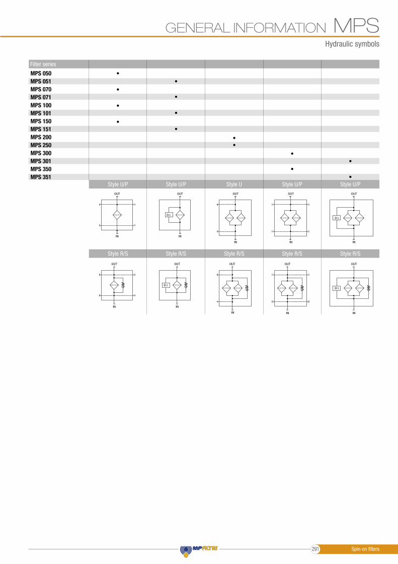
•Style U/P Style U Style U/P Style U/PStyle U/P
Style R/S Style R/S Style R/S Style R/SStyle R/S
OUT
IN
D.I.
OUT
IN
OUT
IN
OUT
IN
D.I.
OUT
IN
OUT
IN
D.I.
OUT
IN
D.I.
OUT
IN
OUT
IN
OUT
IN
Hydraulic symbols
Spin-on filters291
GENERAL INFORMATIONMPSPressure drop
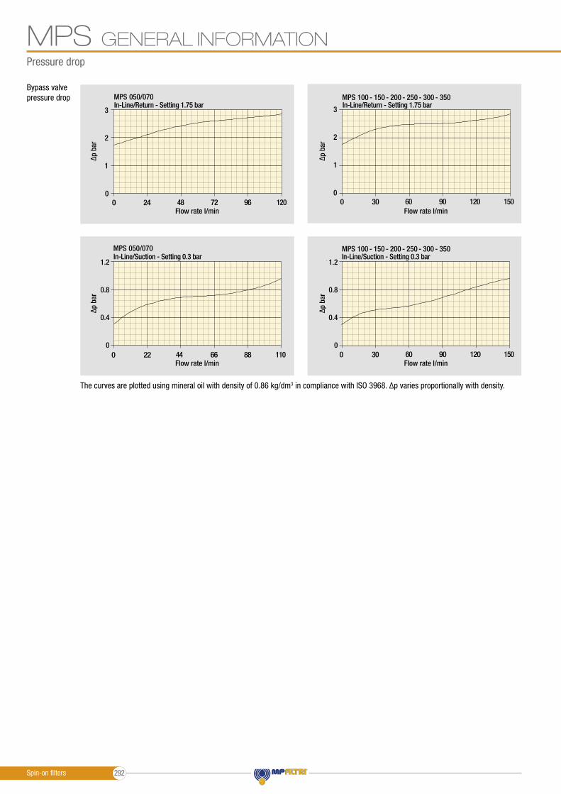
The curves are plotted using mineral oil with density of 0.86 kg/dm3 in compliance with ISO 3968. ∆p varies proportionally with density.
Bypass valve pressure drop
MPSMaximum pressure 12 bar
Flow rate to 365 l/min
3
2
1
00 24 48 72 96 120
MPS 050/070
3
2
1
00 30 60 90 120 150
MPS 100 - 150 - 200 - 250 - 300 - 350
120
80
40
00 22 44 66 88 110
MPS 050/070
120
80
40
00 30 60 90 120 150
MPS 100 - 150 - 200 - 250 - 300 - 350
MPSMaximum pressure 12 bar
Flow rate to 365 l/min
3
2
1
00 24 48 72 96 120
MPS 050/070
3
2
1
00 30 60 90 120 150
MPS 100 - 150 - 200 - 250 - 300 - 350
120
80
40
00 22 44 66 88 110
MPS 050/070
120
80
40
00 30 60 90 120 150
MPS 100 - 150 - 200 - 250 - 300 - 350
MPSMaximum pressure 12 bar
Flow rate to 365 l/min
3
2
1
00 24 48 72 96 120
MPS 050/070
3
2
1
00 30 60 90 120 150
MPS 100 - 150 - 200 - 250 - 300 - 350
120
80
40
00 22 44 66 88 110
MPS 050/070
120
80
40
00 30 60 90 120 150
MPS 100 - 150 - 200 - 250 - 300 - 350
MPSMaximum pressure 12 bar
Flow rate to 365 l/min
3
2
1
00 24 48 72 96 120
MPS 050/070
3
2
1
00 30 60 90 120 150
MPS 100 - 150 - 200 - 250 - 300 - 350
120
80
40
00 22 44 66 88 110
MPS 050/070
120
80
40
00 30 60 90 120 150
MPS 100 - 150 - 200 - 250 - 300 - 350
Flow rate l/min
Flow rate l/min
Flow rate l/min
Flow rate l/min
In-Line/Suction - Setting 0.3 bar
In-Line/Return - Setting 1.75 bar
In-Line/Suction - Setting 0.3 bar
In-Line/Return - Setting 1.75 bar
∆p b
ar∆p
bar
∆p b
ar∆p
bar
1.2
0.8
0.4
0
1.2
0.8
0.4
0
Spin-on filters 292
GENERAL INFORMATION MPSCartridge
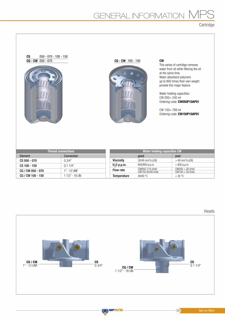
CSCG - CW
050 - 070 - 100 - 150050 - 070 CG - CW 100 - 150 CW
This series of cartridge removes water from oil while filtering the oil at the same time.Water absorbent polymers up to 800 times their own weight provide this major feature.
Water holding capacities:CW 050= 240 mlOrdering code: CW050P10AP01
CW 150= 788 mlOrdering code: CW150P10AP01
Viscosity
Flow rate
H2O p.p.m.
Temperature
30/46 mm2/s (cSt)
CW050 7/15 l/min
600/800 p.p.m.
CW150 20/40 l/min40/60 °C
good> 46 mm2/s (cSt)
CW050 > 20 l/min
> 800 p.p.m.
CW150 > 50 l/min< 30 °C
poorWater holding capacities CW
CS 050 - 070
CG / CW 050 - 070
CS 100 - 150
CG / CW 100 - 150
ElementG 3/4”
1” - 12 UNF
G 1 1/4”
1 1/2” - 16 UN
ConnectionThread connections
Heads
CG / CW1” - 12 UNF CG / CW
1 1/2” - 16 UN
CSG 3/4”
CSG 1 1/4”
Spin-on filters293
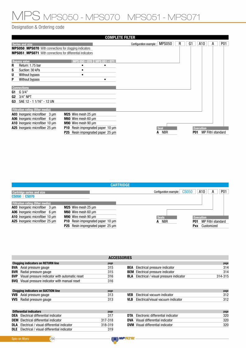
Designation & Ordering code
MPS050 - MPS070 MPS051 - MPS071MPS
CARTRIDGE
COMPLETE FILTER
Series and size
Cartridge series and size
Connections
Bypass valveR
G1
G3
SUP
G2
MPS 051 - 071MPS 050 - 070•••
•
•
G 3/4”
SAE 12 - 1 1/16” - 12 UN
With connections for clogging indicatorsWith connections for differential indicators
Configuration example:
MPS070MPS071
MPS050MPS051
CS050 CS070
Seal
Seals
A
A
NBR
NBR
Execution
Execution
P01
P01Pxx
MP Filtri standard
MP Filtri standardCustomized
3/4” NPT
ACCESSORIES Clogging indicators on RETURN line page page
BVA
BVPBVR
BVQ
BEMBEA
BLA
Axial pressure gauge 315 314
Visual pressure indicator with automatic reset 316 314-315Radial pressure gauge 315 314
Visual pressure indicator with manual reset
Electrical pressure indicator
316
Electrical pressure indicator
Electrical / visual pressure indicator
Clogging indicators on SUCTION line page page
VVBVVS VLB
VEBAxial pressure gauge 313Radial pressure gauge 313 Electrical/visual vacuum indicator 312
Electrical vacuum indicator 312
Configuration example : MPS050 R AA10G1 P01
CS050 A10 A P01
Filtration rating (filter media)A03 M25
A10 M90A06 M60
A25 P10P25
Inorganic microfiber
Return: 1.75 barSuction: 30 kPaWithout bypassWithout bypass
Wire mesh3 µm 25 µm
Inorganic microfiber Wire mesh10 µm 90 µmInorganic microfiber Wire mesh6 µm 60 µm
Inorganic microfiber Resin impregnated paper25 µm 10 µmResin impregnated paper 25 µm
Filtration rating (filter media)A03 M25
A10 M90A06 M60
A25 P10P25
Inorganic microfiber Wire mesh3 µm 25 µm
Inorganic microfiber Wire mesh10 µm 90 µmInorganic microfiber Wire mesh6 µm 60 µm
Inorganic microfiber Resin impregnated paper25 µm 10 µmResin impregnated paper 25 µm
Differential indicators page page
DEA
DLADEM
DLE
DVADTA
DVM
Electrical differential indicator 317
Electrical / visual differential indicator 318-319Electrical differential indicator 317-318
Electrical / visual differential indicator
Visual differential indicator
319
320Electronic differential indicator
Visual differential indicator
320
320
Spin-on filters 294

Dimensions
SF2500
SF2500
MPS050 - MPS070 MPS051 - MPS071 MPSMPS050 - MPS070
MPS051 - MPS071
Filter size
Filter size
Connections
Connections
H[mm]
H[mm]
R
R
T
050070
051071
G1 G2-G3
G1 G2-G3
192256
192256
M61/4” UNC
M61/4” UNC
G 1/8”1/8” NPT
R - depth 12 mmNr. 2 holes
R - depth 12 mmNr. 2 holes
T - Connection for clogging indicatoron Suction Line
T - Connection for clogging indicatoron Suction Line
Connection fordifferential indicator
T - Connection for clogging indicator
on Return Line
T - Connection for clogging indicator
on Return Line
Recommendedclearance spacefor maintenance
Recommendedclearance spacefor maintenance
OUT
OUT
IN
IN
Spin-on filters295

Designation & Ordering code
MPS100 - MPS150 MPS101 - MPS151MPS
CARTRIDGE
COMPLETE FILTER
Series and size
Cartridge series and size
Connections
Bypass valveR
G1
G3
SUP
G2
MPS 101 - 151MPS 100 - 150•••
•
•
G 1 1/4”
SAE 20 - 1 5/8” - 12 UN
With connections for clogging indicatorsWith connections for differential indicators
Configuration example:
MPS150MPS151
MPS100MPS101
CS100 CS150
Seal
Seals
A
A
NBR
NBR
Execution
Execution
P01
P01Pxx
MP Filtri standard
MP Filtri standardCustomized
1 1/4” NPT
Configuration example : MPS100 R AA10G1 P01
CS100 A10 A P01
Filtration rating (filter media)A03 M25
A10 M90A06 M60
A25 P10P25
Inorganic microfiber
Return: 1.75 barSuction: 30 kPaWithout bypassWithout bypass
Wire mesh3 µm 25 µm
Inorganic microfiber Wire mesh10 µm 90 µmInorganic microfiber Wire mesh6 µm 60 µm
Inorganic microfiber Resin impregnated paper25 µm 10 µmResin impregnated paper 25 µm
Filtration rating (filter media)A03 M25
A10 M90A06 M60
A25 P10P25
Inorganic microfiber Wire mesh3 µm 25 µm
Inorganic microfiber Wire mesh10 µm 90 µmInorganic microfiber Wire mesh6 µm 60 µm
Inorganic microfiber Resin impregnated paper25 µm 10 µmResin impregnated paper 25 µm
ACCESSORIES Clogging indicators on RETURN line page page
BVA
BVPBVR
BVQ
BEMBEA
BLA
Axial pressure gauge 315 314
Visual pressure indicator with automatic reset 316 314-315Radial pressure gauge 315 314
Visual pressure indicator with manual reset
Electrical pressure indicator
316
Electrical pressure indicator
Electrical / visual pressure indicator
Clogging indicators on SUCTION line page page
VVBVVS VLB
VEBAxial pressure gauge 313Radial pressure gauge 313 Electrical/visual vacuum indicator 312
Electrical vacuum indicator 312
Differential indicators page page
DEA
DLADEM
DLE
DVADTA
DVM
Electrical differential indicator 317
Electrical / visual differential indicator 318-319Electrical differential indicator 317-318
Electrical / visual differential indicator
Visual differential indicator
319
320Electronic differential indicator
Visual differential indicator
320
320
Spin-on filters 296
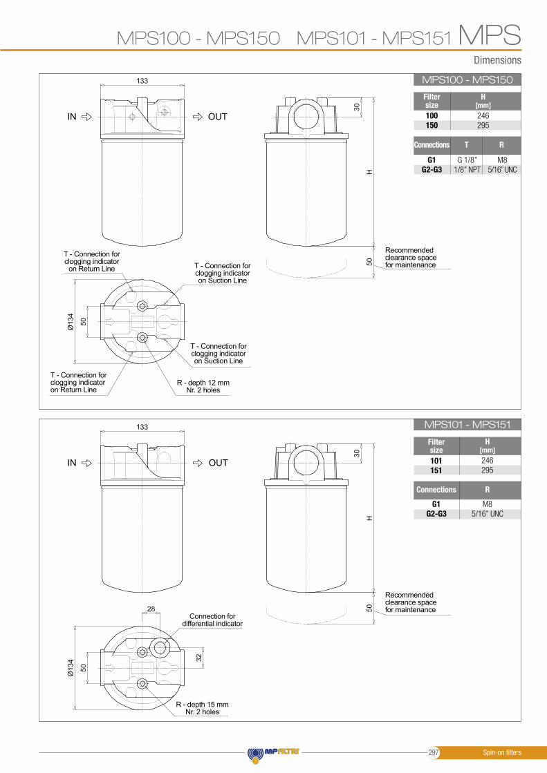
Dimensions
SF2500
SF2500
MPS100 - MPS150 MPS101 - MPS151 MPSMPS100 - MPS150
MPS101 - MPS151
Filter size
Filter size
Connections
Connections
H[mm]
H[mm]
R
R
T
100150
101151
G1 G2-G3
G1 G2-G3
246295
246295
M85/16” UNC
M85/16” UNC
G 1/8”1/8” NPT
R - depth 12 mmNr. 2 holes
R - depth 15 mmNr. 2 holes
T - Connection for clogging indicatoron Suction Line
T - Connection for clogging indicatoron Suction Line
Connection fordifferential indicator
T - Connection for clogging indicator
on Return Line
T - Connection for clogging indicatoron Return Line
Recommendedclearance spacefor maintenance
Recommendedclearance spacefor maintenance
OUT
OUT
IN
IN
Spin-on filters297
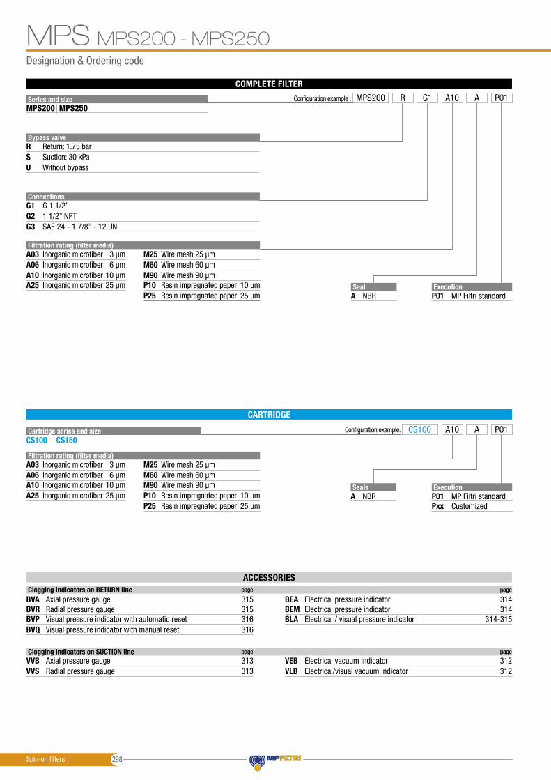
Designation & Ordering code
MPS200 - MPS250MPS
CARTRIDGE
COMPLETE FILTER
Series and size
Cartridge series and size
Connections
Bypass valveR
G1
G3
SU
G2G 1 1/2”
SAE 24 - 1 7/8” - 12 UN
Configuration example:
MPS250MPS200
CS100 CS150
Seal
Seals
A
A
NBR
NBR
Execution
Execution
P01
P01Pxx
MP Filtri standard
MP Filtri standardCustomized
1 1/2” NPT
Configuration example : MPS200 R AA10G1 P01
CS100 A10 A P01
Filtration rating (filter media)A03 M25
A10 M90A06 M60
A25 P10P25
Inorganic microfiber
Return: 1.75 barSuction: 30 kPaWithout bypass
Wire mesh3 µm 25 µm
Inorganic microfiber Wire mesh10 µm 90 µmInorganic microfiber Wire mesh6 µm 60 µm
Inorganic microfiber Resin impregnated paper25 µm 10 µmResin impregnated paper 25 µm
Filtration rating (filter media)A03 M25
A10 M90A06 M60
A25 P10P25
Inorganic microfiber Wire mesh3 µm 25 µm
Inorganic microfiber Wire mesh10 µm 90 µmInorganic microfiber Wire mesh6 µm 60 µm
Inorganic microfiber Resin impregnated paper25 µm 10 µmResin impregnated paper 25 µm
ACCESSORIES Clogging indicators on RETURN line page page
BVA
BVPBVR
BVQ
BEMBEA
BLA
Axial pressure gauge 315 314
Visual pressure indicator with automatic reset 316 314-315Radial pressure gauge 315 314
Visual pressure indicator with manual reset
Electrical pressure indicator
316
Electrical pressure indicator
Electrical / visual pressure indicator
Clogging indicators on SUCTION line page page
VVBVVS VLB
VEBAxial pressure gauge 313Radial pressure gauge 313 Electrical/visual vacuum indicator 312
Electrical vacuum indicator 312
Spin-on filters 298
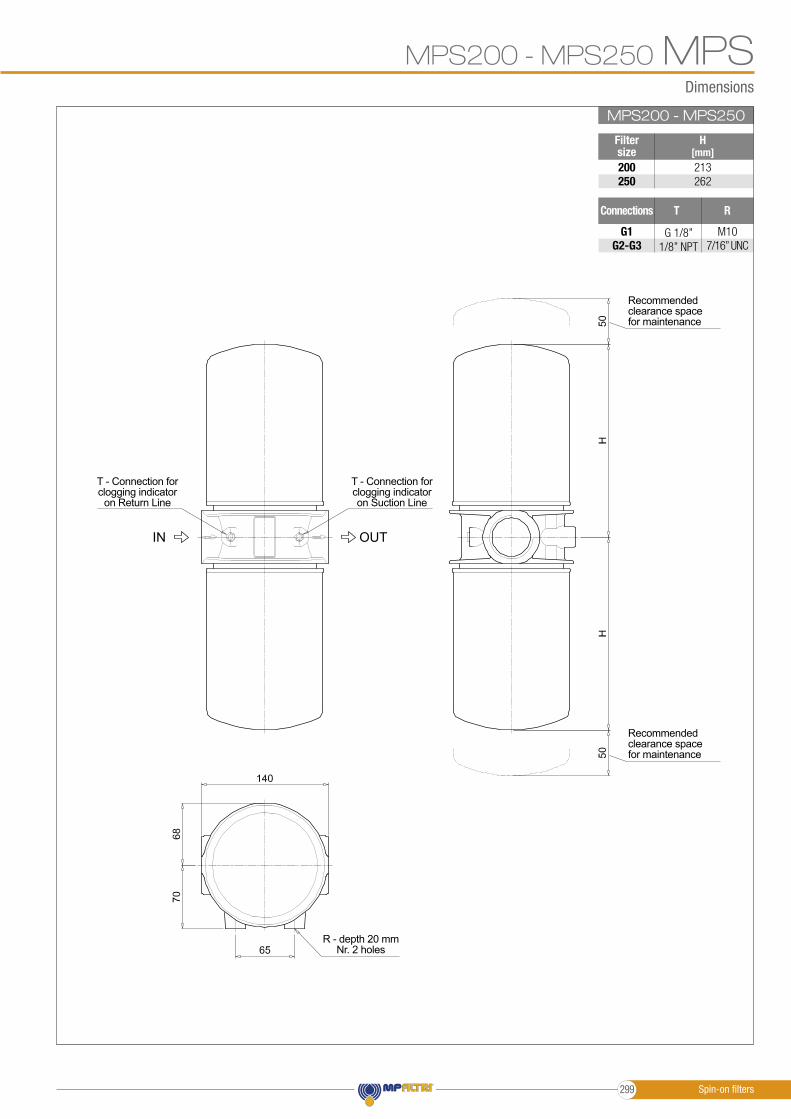
Dimensions
SF2500
MPS200 - MPS250 MPSMPS200 - MPS250
Filter size
Connections
H[mm]
RT
200250
G1 G2-G3
213262
M107/16” UNC
G 1/8”1/8” NPT
R - depth 20 mmNr. 2 holes
T - Connection for clogging indicatoron Suction Line
T - Connection for clogging indicator
on Return Line
Recommendedclearance spacefor maintenance
Recommendedclearance spacefor maintenance
OUTIN
Spin-on filters299
Designation & Ordering code
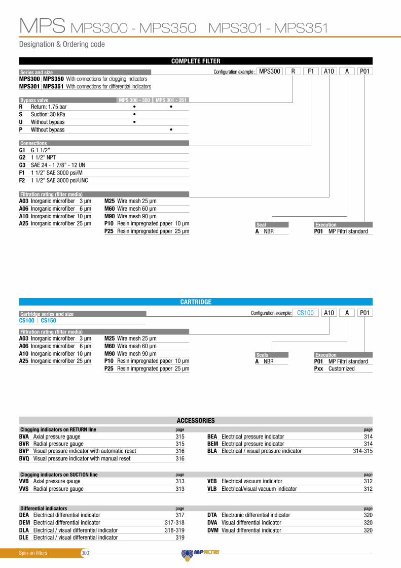
MPS300 - MPS350 MPS301 - MPS351MPS
CARTRIDGE
COMPLETE FILTER
Series and size
Cartridge series and size
Connections
Bypass valveR
G1
F1G3
SUP
G2
F2
MPS 301 - 351MPS 300 - 350•••
•
•
G 1 1/2”
1 1/2” SAE 3000 psi/MSAE 24 - 1 7/8” - 12 UN
With connections for clogging indicatorsWith connections for differential indicators
Configuration example:
MPS350MPS351
MPS300MPS301
CS100 CS150
Seal
Seals
A
A
NBR
NBR
Execution
Execution
P01
P01Pxx
MP Filtri standard
MP Filtri standardCustomized
1 1/2” NPT
1 1/2” SAE 3000 psi/UNC
Configuration example : MPS300 R AA10F1 P01
CS100 A10 A P01
Filtration rating (filter media)A03 M25
A10 M90A06 M60
A25 P10P25
Inorganic microfiber
Return: 1.75 barSuction: 30 kPaWithout bypassWithout bypass
Wire mesh3 µm 25 µm
Inorganic microfiber Wire mesh10 µm 90 µmInorganic microfiber Wire mesh6 µm 60 µm
Inorganic microfiber Resin impregnated paper25 µm 10 µmResin impregnated paper 25 µm
Filtration rating (filter media)A03 M25
A10 M90A06 M60
A25 P10P25
Inorganic microfiber Wire mesh3 µm 25 µm
Inorganic microfiber Wire mesh10 µm 90 µmInorganic microfiber Wire mesh6 µm 60 µm
Inorganic microfiber Resin impregnated paper25 µm 10 µmResin impregnated paper 25 µm
ACCESSORIES Clogging indicators on RETURN line page page
BVA
BVPBVR
BVQ
BEMBEA
BLA
Axial pressure gauge 315 314
Visual pressure indicator with automatic reset 316 314-315Radial pressure gauge 315 314
Visual pressure indicator with manual reset
Electrical pressure indicator
316
Electrical pressure indicator
Electrical / visual pressure indicator
Clogging indicators on SUCTION line page page
VVBVVS VLB
VEBAxial pressure gauge 313Radial pressure gauge 313 Electrical/visual vacuum indicator 312
Electrical vacuum indicator 312
Differential indicators page page
DEA
DLADEM
DLE
DVADTA
DVM
Electrical differential indicator 317
Electrical / visual differential indicator 318-319Electrical differential indicator 317-318
Electrical / visual differential indicator
Visual differential indicator
319
320Electronic differential indicator
Visual differential indicator
320
320
Spin-on filters 300
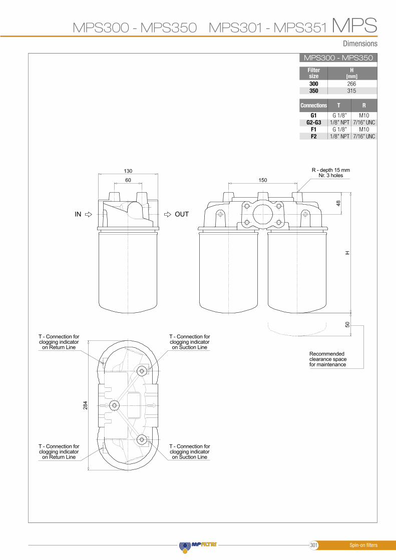
Dimensions
MPS300 - MPS350 MPS301 - MPS351 MPSSF2500MPS300 - MPS350
Filter size300350
266315
G1 G2-G3
F1F2
M107/16” UNC
M107/16” UNC
G 1/8”1/8” NPTG 1/8”
1/8” NPT
Connections
H[mm]
RT
R - depth 15 mmNr. 3 holes
T - Connection for clogging indicatoron Suction Line
T - Connection for clogging indicatoron Suction Line
T - Connection for clogging indicator
on Return Line
T - Connection for clogging indicator
on Return LineRecommendedclearance spacefor maintenance
OUTIN
Spin-on filters301
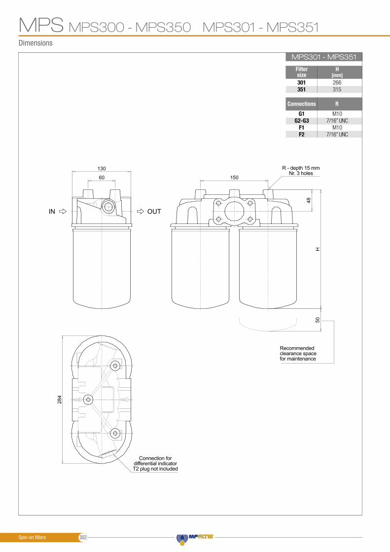
Dimensions
MPSSF2500MPS301 - MPS351
Filter size301351
266315
G1 G2-G3
F1F2
Connections
H[mm]
M107/16” UNC
M107/16” UNC
R
MPS300 - MPS350 MPS301 - MPS351
R - depth 15 mmNr. 3 holes
Recommendedclearance spacefor maintenance
OUTIN
Connection for differential indicatorT2 plug not included
Spin-on filters 302